JP6285902B2 - Rotating equipment for construction machinery - Google Patents
Rotating equipment for construction machinery Download PDFInfo
- Publication number
- JP6285902B2 JP6285902B2 JP2015189653A JP2015189653A JP6285902B2 JP 6285902 B2 JP6285902 B2 JP 6285902B2 JP 2015189653 A JP2015189653 A JP 2015189653A JP 2015189653 A JP2015189653 A JP 2015189653A JP 6285902 B2 JP6285902 B2 JP 6285902B2
- Authority
- JP
- Japan
- Prior art keywords
- elastic body
- fixed
- rotating
- rotation
- accommodation space
- Prior art date
- Legal status (The legal status is an assumption and is not a legal conclusion. Google has not performed a legal analysis and makes no representation as to the accuracy of the status listed.)
- Active
Links
Images


Landscapes
- Sealing Using Fluids, Sealing Without Contact, And Removal Of Oil (AREA)
- Sealing Devices (AREA)
- Sealing Of Bearings (AREA)
Description
本発明は、例えば油圧ショベル等のクローラ式の建設機械に用いられる走行装置、履帯案内ローラ等の回転装置に関する。 The present invention relates to a traveling device used in a crawler-type construction machine such as a hydraulic excavator, and a rotating device such as a crawler belt guide roller.
一般に、油圧ショベル等のクローラ式の建設機械の下部走行体は、左,右のサイドフレームを有するトラックフレームと、各サイドフレームの一端側に設けられる走行装置と、各サイドフレームの他端側に設けられる遊動輪と、走行装置に設けられた駆動輪(スプロケット)と遊動輪とに巻装される履帯とにより大略構成されている。 In general, a lower traveling body of a crawler-type construction machine such as a hydraulic excavator is provided with a track frame having left and right side frames, a traveling device provided on one end side of each side frame, and the other end side of each side frame. It is generally configured by an idler wheel provided, a drive wheel (sprocket) provided in the traveling device, and a crawler belt wound around the idler wheel.
油圧ショベルの走行装置は、通常、回転源となる油圧モータと、該油圧モータの回転を減速して出力する減速装置とからなり、この減速装置は、回転源を収容する固定側ハウジングと、該固定側ハウジングに対して回転可能に設けられ回転源によって駆動される回転側ハウジングと、該回転側ハウジングに収容され回転源の回転を減速する減速機構と、固定側ハウジングと回転側ハウジングとの間の隙間をシールするために当該隙間の内周側に位置して設けられたフローティングシールとを備えて構成されている。 A traveling device of a hydraulic excavator usually includes a hydraulic motor that serves as a rotation source, and a reduction device that decelerates and outputs the rotation of the hydraulic motor. The reduction device includes a fixed-side housing that houses the rotation source, A rotation-side housing that is rotatably provided to the fixed-side housing and is driven by a rotation source, a speed reduction mechanism that is housed in the rotation-side housing and decelerates rotation of the rotation source, and between the fixed-side housing and the rotation-side housing In order to seal the gap, a floating seal provided on the inner peripheral side of the gap is provided.
ここで、固定側ハウジングと回転側ハウジングとの間の隙間は、軸方向で対面する固定側ハウジングの端面と回転側ハウジングの端面との間に環状に形成され、フローティングシールは、前記隙間の内周側に配置され互いに摺接する摺接面をもった一対のシールリングと、前記隙間を挟んで各シールリングのうち一方のシールリングと固定側ハウジングとの間及び他方のシールリングと回転側ハウジングとの間にそれぞれ設けられた一対のOリングとにより構成されている。そして、各シールリングの摺接面が、Oリングの弾性力によって適度な面圧をもって摺接することにより、減速機内に潤滑油を封止し、この潤滑油によって減速装置を潤滑することができる。 Here, the gap between the fixed housing and the rotary housing is formed in an annular shape between the end face of the fixed housing and the end face of the rotary housing facing each other in the axial direction, and the floating seal is within the gap. A pair of seal rings arranged on the circumferential side and having sliding contact surfaces that are in sliding contact with each other, and between the one seal ring and the fixed-side housing and between the other seal ring and the rotation-side housing across the gap. And a pair of O-rings provided between the two. The sliding contact surface of each seal ring is in sliding contact with an appropriate surface pressure by the elastic force of the O-ring, so that the lubricating oil can be sealed in the reduction gear, and the reduction gear can be lubricated with this lubricating oil.
ところで、油圧ショベルは、泥濘地等の不整地を走行するため、固定側ハウジングと回転側ハウジングとの間の隙間には土砂等の異物が侵入する。隙間内に侵入した土砂等は、外部に排出されることなくフローティングシールの周囲に堆積するようになる。 By the way, since the hydraulic excavator travels on rough terrain such as muddy ground, foreign matters such as earth and sand enter a gap between the stationary housing and the rotating housing. The earth and sand that has entered the gap accumulates around the floating seal without being discharged to the outside.
フローティングシールの周囲に堆積した土砂等は、環状のOリングに対して圧力を不均一に作用させる。この結果、Oリングの弾性力によって一対のシールリングの摺接面に作用する面圧が不均一となり、フローティングシールによってシールされた潤滑油が外部に漏れることにより、減速装置に対する潤滑性が損なわれる可能性がある。 The earth and sand deposited around the floating seal causes pressure to act unevenly on the annular O-ring. As a result, the surface pressure acting on the sliding contact surfaces of the pair of seal rings becomes non-uniform due to the elastic force of the O-ring, and the lubricating oil sealed by the floating seal leaks to the outside, thereby impairing the lubricity of the reduction gear. there is a possibility.
一方、固定体側の端面にシール収容溝を形成し、このシール収容溝内に、低摩擦性の樹脂材料により形成されたシールリングと、シールリングを固定体の端面に押付けるOリング、Xリング等の弾性体とを配置することにより、固定体と回転体との間に形成された隙間をシールする構成となったシール構造が知られている(特許文献1,2)。 On the other hand, a seal housing groove is formed on the end surface on the fixed body side, a seal ring formed of a low friction resin material in the seal housing groove, and an O-ring and an X ring that press the seal ring against the end surface of the fixed body There is known a sealing structure in which a gap formed between a fixed body and a rotating body is sealed by disposing an elastic body such as (Patent Documents 1 and 2).
しかし、上述した従来技術によるシール構造においても、土砂がシール収容溝内に侵入し、このシール収容溝内に堆積した場合には、堆積した土砂からOリング等の弾性体に対して不均一な圧力が作用する。この結果、弾性体からシールリングに作用する押付力が不均一となり、シールリングのシール性が低下してしまうという問題がある。 However, even in the above-described seal structure according to the prior art, when the earth and sand penetrates into the seal accommodation groove and accumulates in the seal accommodation groove, the accumulated earth and sand are uneven with respect to the elastic body such as an O-ring. Pressure acts. As a result, the pressing force acting on the seal ring from the elastic body becomes non-uniform, and there is a problem that the sealing performance of the seal ring is lowered.
本発明は上述した従来技術の問題に鑑みなされたもので、固定体と回転体との間に形成された隙間を通じてフローティングシールの周囲に土砂等の異物が侵入するのを抑制し、フローティングシールのシール性を長期に亘って適正に保つことができるようにした建設機械の回転装置を提供することを目的としている。 The present invention has been made in view of the above-described problems of the prior art, and suppresses the intrusion of foreign matter such as earth and sand around the floating seal through a gap formed between the fixed body and the rotating body. An object of the present invention is to provide a construction machine rotating device capable of maintaining a proper sealability over a long period of time.
上述した課題を解決するため本発明は、建設機械の車体に固定された固定体と、前記固定体に対し回転可能に設けられた回転体と、軸方向で対面する前記固定体の固定体側端面と前記回転体の回転体側端面との間に形成された隙間と、前記隙間よりも径方向の内側に位置して前記固定体と前記回転体との間に設けられ、前記隙間をシールするフローティングシールと、前記隙間よりも径方向の外側に位置して前記固定体と前記回転体との間に設けられ、前記隙間に連通するラビリンスとを備えてなる建設機械の回転装置に適用される。 In order to solve the above-described problems, the present invention provides a fixed body fixed to a vehicle body of a construction machine, a rotating body rotatably provided to the fixed body, and a fixed body side end surface of the fixed body facing in the axial direction. And a gap formed between the rotating body side end surface of the rotating body and a floating member that is provided between the fixed body and the rotating body and is located radially inside the gap and seals the gap. The present invention is applied to a rotation device for a construction machine that includes a seal and a labyrinth that is provided between the fixed body and the rotating body and is positioned radially outside the gap and communicates with the gap.
そして、本発明が採用する構成の特徴は、前記隙間よりも径方向の外側でかつ前記ラビリンスよりも径方向の内側に位置して前記固定体側端面と前記回転体側端面とに設けられ、前記隙間よりも軸方向寸法が大きな弾性体収容空間と、前記弾性体収容空間内に設けられ、前記回転体に対して廻止めされた状態で前記隙間を径方向の外側から覆う環状の弾性体と、前記弾性体を前記固定体に向けて軸方向に押付けるばねとを備え、前記弾性体の外周面には、前記固定体から前記回転体に向けて外径寸法が徐々に小さくなる傾斜面を設けたことにある。 A feature of the configuration employed by the present invention is that the gap is provided on the fixed body side end face and the rotating body side end face, located on the outer side in the radial direction than the gap and on the inner side in the radial direction with respect to the labyrinth. An elastic body accommodating space having a larger axial dimension than that, an annular elastic body provided in the elastic body accommodating space and covering the gap from the outside in the radial direction in a state in which the space is stopped with respect to the rotating body, A spring that presses the elastic body in the axial direction toward the fixed body, and an outer peripheral surface of the elastic body has an inclined surface that gradually decreases in outer diameter from the fixed body toward the rotating body. It is in providing.
本発明によれば、固定体と回転体との間の隙間よりも軸方向寸法が大きな弾性体収容空間内に弾性体を設け、この弾性体によって隙間を径方向の外側から覆うことにより、土砂等の異物が隙間を通じてフローティングシールの周囲に侵入するのを抑えることができる。この結果、フローティングシールのシール性を長期に亘って適正に保ち、回転体を円滑に回転させることができる。 According to the present invention, the elastic body is provided in the elastic body accommodating space having a larger axial dimension than the gap between the fixed body and the rotating body, and the gap is covered from the outside in the radial direction by the elastic body. It is possible to prevent foreign substances such as from entering the periphery of the floating seal through the gap. As a result, the sealing performance of the floating seal can be maintained properly over a long period of time, and the rotating body can be rotated smoothly.
しかも、弾性体収容空間内に収容された弾性体を、ばねによって固定体に向けて軸方向に押付けることにより、弾性体を固定体により密に当接させることができ、弾性体によって隙間をより強固に閉塞することができる。さらに、弾性体の外周面に傾斜面を設けることにより、弾性体収容空間内に土砂が堆積した場合に、この堆積した土砂が弾性体の傾斜面を押圧する力を利用して弾性体を固定体に押付けることができるので、土砂等の異物が隙間を通じてフローティングシールの周囲に侵入するのを長期に亘って抑制することができる。 In addition, by pressing the elastic body housed in the elastic body housing space in the axial direction toward the fixed body by the spring, the elastic body can be brought into close contact with the fixed body, and the gap is formed by the elastic body. It can block more firmly. Furthermore, by providing an inclined surface on the outer peripheral surface of the elastic body, when the earth and sand accumulates in the elastic body accommodation space, the elastic body is fixed using the force by which the accumulated earth and sand presses the inclined surface of the elastic body. Since it can be pressed against the body, foreign matter such as earth and sand can be prevented from entering the periphery of the floating seal through the gap over a long period of time.
以下、本発明に係る建設機械の回転装置の実施の形態について、添付図面を参照しつつ詳細に説明する。図1ないし図6は本発明の第1の実施の形態を示し、回転装置として油圧ショベルの走行装置を例示している。 DESCRIPTION OF THE PREFERRED EMBODIMENTS Hereinafter, embodiments of a construction machine rotating device according to the present invention will be described in detail with reference to the accompanying drawings. 1 to 6 show a first embodiment of the present invention and illustrate a traveling device of a hydraulic excavator as a rotating device.
図中、油圧ショベル1は建設機械の代表例であり、この油圧ショベル1の車体は、自走可能なクローラ式の下部走行体2と、該下部走行体2上に旋回可能に搭載された上部旋回体3とにより構成されている。上部旋回体3の前部側には、作業装置4が俯仰動可能に設けられ、油圧ショベル1は、作業装置4を用いて土砂等の掘削作業を行う。
In the drawing, a hydraulic excavator 1 is a typical example of a construction machine, and a vehicle body of the hydraulic excavator 1 includes a self-propelled crawler-type lower traveling
下部走行体2は、前,後方向に延びる左,右のサイドフレーム5A(左側のみ図示)を備えたトラックフレーム5と、各サイドフレーム5Aの長手方向の一端側に設けられた後述の走行装置9と、各サイドフレーム5Aの長手方向の他端側に設けられた遊動輪6と、各サイドフレーム5Aの下側に設けられた複数の下案内ローラ7と、遊動輪6、各下案内ローラ7、後述の駆動輪21に巻回された履帯8とを含んで構成されている。
The lower traveling
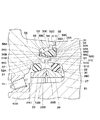
回転装置としての走行装置9は、図2に示すように、各サイドフレーム5Aの長手方向の一端側に固定された走行装置ブラケット10と、走行装置ブラケット10に取付けられた油圧モータ11と、該油圧モータ11の回転を減速する後述の減速装置12とを含んで構成されている。走行装置9は、油圧モータ11の回転を減速装置12によって減速することにより、後述の駆動輪21を大きなトルクをもって回転させ、該駆動輪21と遊動輪6とに巻装された履帯8を周回駆動させるものである。
As shown in FIG. 2, the
減速装置12は、油圧モータ11の回転を減速するものである。この減速装置12は、後述の固定側ハウジング13、回転側ハウジング15、遊星歯車減速機構24,25,26、フローティングシール27、弾性体収容空間33、弾性体36等を含んで構成されている。
The speed reducer 12 decelerates the rotation of the
固定体としての固定側ハウジング13は、走行装置ブラケット10に固定して設けられている。この固定側ハウジング13は、油圧モータ11が取付けられるものである。ここで、固定側ハウジング13は大径なフランジ部13Aを有し、このフランジ部13Aは、複数のボルト14を用いて走行装置ブラケット10に固定されている。
The
図3に示すように、走行装置ブラケット10から突出した固定側ハウジング13の先端側には、後述の回転側ハウジング15を支持するハウジング支持部13Bと、後述する遊星歯車減速機構26のキャリア26Cが結合される雄スプライン部13Cとが設けられている。また、フランジ部13Aとハウジング支持部13Bとの間には、後述の固定側シールリング28が取付けられる円筒状のシール装着部13Dが設けられている。シール装着部13Dの先端部は、フローティングシール27よりも径方向の外側に位置する環状の固定体側端面13Eとなり、この固定体側端面13Eは、後述する回転側ハウジング15の回転体側端面15Cと軸方向で間隔をもって対面している。また、固定体側端面13Eの外周縁部には、後述のラビリンス32を構成する環状の固定体側凹陥部13Fが形成されている。
As shown in FIG. 3, a
回転体としての回転側ハウジング15は、固定側ハウジング13に対して回転可能に設けられている。回転側ハウジング15は、全体として有蓋円筒状に形成され、その内部に遊星歯車減速機構24,25,26を収容するものである。ここで、回転側ハウジング15は、固定側ハウジング13に設けられたハウジング支持部13Bの外周側に配置される環状のフランジ部15Aと、フランジ部15Aにボルト16を用いて固定され内周側に内歯17A,17Bが形成された円筒状のリングギヤ17と、該リングギヤ17を施蓋する円板状の蓋体18とを含んで構成されている。
The
フランジ部15Aの内周側は、固定側ハウジング13のハウジング支持部13Bに軸受19を介して回転可能に取付けられている。フランジ部15Aの外周側には、複数のボルト20を用いて駆動輪(スプロケット)21が固着されている。また、フランジ部15Aの内周側には、後述の回転側シールリング29が取付けられる円筒状のシール装着部15Bが設けられている。シール装着部15Bの先端部は、フローティングシール27よりも径方向の外側に位置し、固定側ハウジング13の固定体側端面13Eと軸方向で対面する環状の回転体側端面15Cとなっている。
The inner peripheral side of the
回転体側端面15Cと固定側ハウジング13の固定体側端面13Eとの間には、後述する軸方向の隙間22が全周に亘って形成されている。また、回転体側端面15Cの外周側には、固定側ハウジング13に向けて突出する円筒状の回転体側突起部15Dが設けられている。回転体側突起部15Dは、固定側ハウジング13の固定体側凹陥部13Fと径方向で隙間をもって対面し、後述のラビリンス32を構成している。
Between the rotating body side end face 15 </ b> C and the fixed body side end face 13 </ b> E of the fixed
軸方向の隙間22は、固定側ハウジング13の固定体側端面13Eと回転側ハウジング15を構成するフランジ部15Aの回転体側端面15Cとの間に、全周に亘って環状に形成されている。隙間22よりも径方向の内側には、フローティングシール27が設けられている。
The
回転軸23は、回転側ハウジング15内に設けられ、油圧モータ11の回転出力を導出するものである。回転軸23の基端側は油圧モータ11の出力軸に連結され、回転軸23の先端側はリングギヤ17内を軸方向に伸長している。蓋体18の近傍に位置する回転軸23の先端部には、後述の太陽歯車24Aが一体形成されている。
The
回転側ハウジング15内には、3段の遊星歯車減速機構24,25,26が設けられている。これら3段の遊星歯車減速機構24,25,26は、油圧モータ11の回転を3段減速し、回転側ハウジング15のフランジ部15Aに取付けられた駆動輪21を大きなトルクをもって回転させるものである。
Three-stage planetary
ここで、1段目の遊星歯車減速機構24は、回転軸23の先端部に一体形成された太陽歯車24Aと、太陽歯車24Aとリングギヤ17の内歯17Aとに噛合し、太陽歯車24Aの周囲を自転しつつ公転する複数の遊星歯車24B(1個のみ図示)と、各遊星歯車24Bを回転可能に支持するキャリア24Cとを含んで構成されている。そして、1段目の遊星歯車減速機構24は、太陽歯車24Aの回転を減速し、各遊星歯車24Bの公転をキャリア24Cを介して後述する2段目の太陽歯車25Aに伝達する。
Here, the first stage planetary gear
2段目の遊星歯車減速機構25は、回転軸23に遊嵌された状態で1段目のキャリア24Cにスプライン結合された円筒状の太陽歯車25Aと、太陽歯車25Aとリングギヤ17の内歯17Aとに噛合し、太陽歯車25Aの周囲を自転しつつ公転する複数の遊星歯車25B(1個のみ図示)と、各遊星歯車25Bを回転可能に支持するキャリア25Cとを含んで構成されている。そして、2段目の遊星歯車減速機構25は、太陽歯車25Aの回転を減速し、各遊星歯車25Bの公転をキャリア25Cを介して後述する3段目の太陽歯車26Aに伝達する。
The second-stage planetary gear
3段目の遊星歯車減速機構26は、回転軸23に遊嵌された状態で2段目のキャリア25Cにスプライン結合された円筒状の太陽歯車26Aと、太陽歯車26Aとリングギヤ17の内歯17Bとに噛合し、太陽歯車26Aの周囲を自転しつつ公転する複数の遊星歯車26B(1個のみ図示)と、各遊星歯車26Bを回転可能に支持するキャリア26Cとを含んで構成されている。
The third-stage planetary gear
ここで、3段目のキャリア26Cは、固定側ハウジング13の雄スプライン部13Cにスプライン結合されている。従って、キャリア26Cに支持された各遊星歯車26Bの公転は、リングギヤ17の内歯17Bを介して回転側ハウジング15に伝達される。これにより、回転側ハウジング15は、遊星歯車減速機構24,25,26によって3段減速された状態で、固定側ハウジング13に対して回転する構成となっている。
Here, the third-
ここで、回転側ハウジング15内には、各遊星歯車減速機構24,25,26、軸受19等を潤滑するための潤滑油が充填され、この潤滑油Lは、フローティングシール27によって回転側ハウジング15内に封止される構成となっている。
Here, the rotation-
フローティングシール27は、固定側ハウジング13と回転側ハウジング15との間に形成された隙間22よりも径方向の内側に設けられている。フローティングシール27は、回転側ハウジング15内に潤滑油Lを封止すると共に、泥水、土砂等の異物が回転側ハウジング15内に侵入するのを抑制するためのものである。ここで、フローティングシール27は、図3及び図4に示すように、後述の固定側シールリング28、回転側シールリング29、固定側Oリング30、回転側Oリング31を含んで構成されている。
The floating
固定側シールリング28は、固定側ハウジング13に設けられたシール装着部13Dの内周側に配置されている。固定側シールリング28は、回転側シールリング29と対をなすもので、例えば耐摩耗性、耐食性に優れた金属材料を用いて円筒状に形成されている。ここで、固定側シールリング28には大径鍔部28Aが設けられ、大径鍔部28Aの端面には環状の摺接面28Bが形成されている。また、シール装着部13Dの内周面13Gと対面する固定側シールリング28の外周面28Cは、大径鍔部28Aに向けて徐々に拡径するテーパ面となり、この外周面28Cとシール装着部13Dの内周面13Gとの間には、後述の固定側Oリング30が設けられている。
The fixed
回転側シールリング29は、回転側ハウジング15のフランジ部15Aに設けられたシール装着部15Bの内周側に配置されている。回転側シールリング29は、固定側シールリング28と同一部品からなっている。ここで、回転側シールリング29には大径鍔部29Aが設けられ、大径鍔部29Aの端面には環状の摺接面29Bが形成されている。また、シール装着部15Bの内周面15Eと対面する回転側シールリング29の外周面29Cは、大径鍔部29Aに向けて徐々に拡径するテーパ面となり、この外周面29Cとシール装着部15Bの内周面15Eとの間には、後述の回転側Oリング31が設けられている。
The rotation-
固定側Oリング30は、固定側ハウジング13に設けられたシール装着部13Dの内周面13Gと固定側シールリング28の外周面28Cとの間に設けられている。固定側Oリング30は、回転側Oリング31と対をなすもので、例えばブタジエンゴム等の耐油性、弾性を有するゴム材料等を用いて環状に形成されている。そして、固定側Oリング30は、固定側ハウジング13のシール装着部13Dと固定側シールリング28との間をシールすると共に、固定側シールリング28を回転側シールリング29に向けて軸方向に常時押圧するものである。
The fixed-side O-
回転側Oリング31は、回転側ハウジング15のフランジ部15Aに設けられたシール装着部15Bの内周面15Eと回転側シールリング29の外周面29Cとの間に設けられている。回転側Oリング31は、固定側Oリング30と同一部品からなり、フランジ部15Aのシール装着部15Bと回転側シールリング29との間をシールすると共に、回転側シールリング29を固定側シールリング28に向けて軸方向に常時押圧するものである。
The rotation-side O-
これにより、固定側シールリング28の摺接面28Bと、回転側シールリング29の摺接面29Bとは、固定側Oリング30と回転側Oリング31から付与される軸方向の押圧力によって適正に摺接する。従って、固定側ハウジング13に対して回転側ハウジング15が回転するときには、固定側シールリング28の摺接面28Bと回転側シールリング29の摺接面29Bとが液密に摺接し、回転側ハウジング15内に潤滑油Lを封止することができる。
Thereby, the sliding
ラビリンス32は、隙間22よりも径方向の外側に位置して固定側ハウジング13と回転側ハウジング15との間に設けられ、隙間22に連通している。ここで、ラビリンス32は、図3に示すように、固定体側端面13Eの外周側に形成された環状の固定体側凹陥部13Fと、回転体側端面15Cの外周側に形成された円筒状の回転体側突起部15Dとの間に形成されている。ラビリンス32は、クランク状の迷路を形成することにより、大きな土砂等が後述する弾性体収容空間33内に侵入するのを抑制するためのものである。
The
次に、第1の実施の形態に用いられる弾性体収容空間33、弾性体36について説明する。
Next, the elastic
弾性体収容空間33は、隙間22よりも径方向の外側でかつラビリンス32よりも径方向の内側に位置して固定体側端面13Eと回転体側端面15Cとに設けられている。ここで、図3及び図4に示すように、弾性体収容空間33は、固定体側端面13Eに凹設された環状の固定体側収容空間34と、回転体側端面15Cに凹設された環状の回転体側収容空間35とにより構成されている。
The elastic
固定体側収容空間34は、回転側ハウジング15の回転軸を中心とする環状溝として形成されている。固定体側収容空間34は、溝底となる底面34Aと、環状溝の内径側に位置する内径面34Bと、環状溝の外径側に位置する外径面34Cとにより囲まれた四角形の断面形状を有している。そして、固定体側収容空間34内には、後述する弾性体36の固定体当接部36Aが摺動可能に嵌合している。
The stationary body
回転体側収容空間35は、回転側ハウジング15の回転軸を中心とする環状溝として形成されている。回転体側収容空間35も、溝底となる底面35Aと、環状溝の内径側に位置する内径面35Bと、環状溝の外径側に位置する外径面35Cとにより囲まれた四角形の断面形状を有している。ここで、回転体側収容空間35の内径面35Bには、回転体側端面15Cから底面35Aに向けて方向に延びる2本の長溝35Dが形成されている(図6参照)。これら2本の長溝35Dは、周方向に180度の間隔をもって配置され、後述のボール37が係合するものである。
The rotating body
弾性体36は、弾性体収容空間33内に設けられ、固定体側端面13Eと回転体側端面15Cとの間に形成された隙間22を径方向の外側から覆っている。弾性体36は、樹脂材料を用いて円筒状に形成されている。
The
ここで、弾性体36は、図3ないし図6に示すように、固定体側収容空間34の底面34Aに摺動可能に当接する固定体当接部36Aと、回転体側収容空間35の底面35Aに当接する回転体当接部36Bとを有している。回転体当接部36Bには、逆J字状をなす薄肉な屈曲部36Cが一体形成され、この屈曲部36Cは、弾性体36を固定側ハウジング13に向けて軸方向に押付けるばねを構成している。これにより、弾性体収容空間33内に収容された弾性体36に対し、回転体側収容空間35の底面35Aに当接した屈曲部36Cからのばね力が常に作用するので、弾性体36の固定体当接部36Aを、固定体側収容空間34の底面34Aにより密に当接させることができる構成となっている。
Here, as shown in FIGS. 3 to 6, the
弾性体36の外周面は、固定体側収容空間34に係合する円筒面36Dと、この円筒面36Dから回転体当接部36Bに向けて外径寸法が徐々に小さくなるように傾斜した傾斜面36Eとを含んで構成されている。このように、弾性体36の外周面に傾斜面36Eを設けることにより、図3に示すように、弾性体収容空間33内に二点鎖線で示す土砂Mが堆積した場合に、この堆積した土砂Mが、弾性体36の傾斜面36Eを矢印F方向に押圧し、弾性体36の固定体当接部36Aを固定体側収容空間34の底面34Aに押付けることができる。
The outer peripheral surface of the
ここで、図4に示すように、円筒面36Dの軸方向寸法Aは、固定体側端面13Eから固定体側収容空間34の底面34Aまでの軸方向寸法(深さ寸法)Bよりも小さく設定されている(A<B)。これにより、図3に示すように、弾性体36の円筒面36Dを固定体側収容空間34内に収めることができ、ラビリンス32を通じて弾性体収容空間33内に侵入した土砂等が、傾斜面36Eを設けた事で回転体側収容空間35の底面35A側に堆積するようになる。従って、堆積した土砂が傾斜面36Eを押して固定体当接部36Aを押圧することにより、土砂が、弾性体36の固定体当接部36Aと固定体側収容空間34の底面34Aとの摺接面に直接的に侵入するのを抑えることができる。
Here, as shown in FIG. 4, the axial dimension A of the
一方、弾性体36の内周面36Fには、周方向に180度の間隔をもって2個の半球状の凹窪部36Gが設けられている。これら各凹窪部36Gは、回転体側収容空間35の底面35Aに形成された2本の長溝35Dの奥部35Eに対応する位置に配置されている。そして、回転体側収容空間35の底面35Aに形成された各長溝35Dと弾性体36の各凹窪部36Gには、廻止め部材としてのボール37が嵌合している。
On the other hand, two hemispherical
従って、弾性体収容空間33内に収容された弾性体36は、回転側ハウジング15に対し、軸方向に移動可能でかつ周方向に廻止めされることにより、固定体当接部36Aを固定体側収容空間34の底面34Aに摺接させる。このように、回転側ハウジング15に対して弾性体36を回止めすることにより、油圧ショベル1の走行時に土砂等がラビリンス32を通じて弾性体収容空間33内に侵入した場合に、この土砂が弾性体36の周方向に均一に付着することになり、弾性体36に作用する土砂からの圧力を均一化することができる構成となっている。
Therefore, the
第1の実施の形態による回転装置としての走行装置9は、上述の如き構成を有するもので、油圧ショベル1の走行時に油圧モータ11を回転させると、この油圧モータ11の回転が減速装置12の遊星歯車減速機構24,25,26によって3段減速され、回転側ハウジング15に伝達される。これにより、回転側ハウジング15が大きなトルクをもって回転し、この回転側ハウジング15に固定した駆動輪21と遊動輪6とに巻回された履帯8が駆動され、油圧ショベル1が走行する。
The traveling
ここで、フローティングシール27の回転側シールリング29は、回転側ハウジング15一体に回転し、この回転側シールリング29は、摺接面29Bを固定側シールリング28の摺接面28Bに摺接させることにより、回転側ハウジング15と固定側ハウジング13との間を液密にシールする。これにより、回転側ハウジング15内に潤滑油Lを保持し、この潤滑油Lによって軸受19、遊星歯車減速機構24,25,26等を適正に潤滑することができ、回転側ハウジング15を円滑に回転させることができる。
Here, the rotation-
このとき、弾性体収容空間33内に収容された弾性体36は、回転側ハウジング15と一体に回転しつつ、固定側ハウジング13の固定体側端面13Eと回転側ハウジング15の回転体側端面15Cとの間に形成された軸方向の隙間22を径方向の外側から覆う。これにより、油圧ショベル1が泥濘地を走行するときに、土砂等がラビリンス32に侵入したとしても、この土砂等が隙間22を通じてフローティングシール27の周囲に侵入するのを、弾性体36によって抑制することができる。
At this time, the
これにより、フローティングシール27の周囲に堆積した土砂から、フローティングシール27の固定側Oリング30、回転側Oリング31に対して圧力が作用するのを防止することができる。従って、各Oリング30,31の弾性力によって、固定側シールリング28の摺接面28Bと回転側シールリング29の摺接面29Bとを、全周に亘って均一な面圧をもって適正に摺接させることができ、フローティングシール27のシール性を確保することができる。
Thereby, it is possible to prevent pressure from acting on the fixed-side O-
この結果、回転側ハウジング15内に充填された潤滑油Lが外部に漏れるのを防止し、この潤滑油Lによって軸受19、遊星歯車減速機構24,25,26等を適正に潤滑することができるので、回転側ハウジング15を長期に亘って円滑に回転させることができ、減速装置12全体の信頼性を高めることができる。
As a result, the lubricating oil L filled in the
この場合、第1の実施の形態によれば、弾性体36は、固定体側収容空間34の底面34Aに摺動可能に当接する固定体当接部36Aと、回転体側収容空間35の底面35Aに当接する回転体当接部36Bとを有し、回転体当接部36Bには、逆J字状をなす薄肉な屈曲部36Cが一体形成されている。これにより、弾性体収容空間33内に収容された弾性体36に対し、回転体側収容空間35の底面35Aに当接した屈曲部36Cからのばね力が常に作用するので、弾性体36の固定体当接部36Aを、固定体側収容空間34の底面34Aにより密に当接(摺接)させることができ、弾性体36によって隙間22をより強固に閉塞することができる。
In this case, according to the first embodiment, the
また、第1の実施の形態によれば、弾性体36の外周面を、固定体側収容空間34に係合する円筒面36Dと、この円筒面36Dから回転体当接部36Bに向けて外径寸法が徐々に小さくなるように傾斜した傾斜面36Eとを含んで構成している。このように、弾性体36の外周面に傾斜面36Eを設けることにより、図3に示すように、弾性体収容空間33内に二点鎖線で示す土砂Mが堆積した場合に、この堆積した土砂Mが、弾性体36の傾斜面36Eを矢印F方向に押圧するようになる。この結果、堆積した土砂Mを利用して、弾性体36の固定体当接部36Aを常に固定体側収容空間34の底面34Aに押付けることができ、弾性体36によって隙間22をより強固に閉塞することができる。
In addition, according to the first embodiment, the outer peripheral surface of the
さらに、第1の実施の形態によれば、回転体側収容空間35の底面35Aに2本の長溝35Dを設けると共に、弾性体36の内周面36Fに、周方向に離間して2個の半球状の凹窪部36Gを設け、これら長溝35Dと凹窪部36Gとに廻止め部材としてのボール37を嵌合させことにより、弾性体36を、回転側ハウジング15に対して周方向に廻止めすることができる。この結果、弾性体36は、回転側ハウジング15と一体に回転するので、弾性体収容空間33内に堆積した土砂は、弾性体36の周方向にほぼ均一に堆積して固着することになり、弾性体36の全周に亘って傾斜面36Eをほぼ均一に押圧するようになる。この結果、堆積した土砂から弾性体36の傾斜面36Eに作用する圧力が周方向で偏るのを回避することができ、弾性体36の傾斜面36Eに対し全周に亘って均一な圧力を付与することができる。
Furthermore, according to the first embodiment, two
しかも、円筒面36Dの軸方向寸法Aを、固定体側端面13Eから固定体側収容空間34の底面34Aまでの軸方向寸法(深さ寸法)Bよりも小さく設定している。これにより、図3に示すように、弾性体36の円筒面36Dを固定体側収容空間34内に収めることができ、ラビリンス32を通じて弾性体収容空間33内に侵入した土砂等が、傾斜面36Eを設けた事で回転体側収容空間35の底面35A側に堆積するようになる。従って、堆積した土砂が傾斜面36Eを押して固定体当接部36Aを押圧することにより、土砂が、弾性体36の固定体当接部36Aと固定体側収容空間34の底面34Aとの摺接面に直接的に侵入するのを抑えることができる。
Moreover, the axial dimension A of the
次に、図7は本発明の第2の実施の形態を示し、本実施の形態の特徴は、弾性体の内周面に設けた内周側突起部により、弾性体を固定体に向けて押付けるばねを形成したことにある。なお、第2の実施の形態では、上述した第1の実施の形態と同一の構成要素に同一符号を付し、その説明を省略するものとする。 Next, FIG. 7 shows a second embodiment of the present invention. The feature of the present embodiment is that the elastic body is directed to the fixed body by the inner peripheral projection provided on the inner peripheral surface of the elastic body. This is because a spring to be pressed is formed. In the second embodiment, the same components as those in the first embodiment described above are denoted by the same reference numerals, and description thereof is omitted.
第2の実施の形態に用いられる弾性体41は、弾性体収容空間33内に設けられている。弾性体41は、第1の実施の形態による弾性体36とほぼ同様に、樹脂材料を用いて円筒状に形成され、固定体側収容空間34の底面34Aに当接する固定体当接部41Aと、回転体側収容空間35の底面35Aに当接する回転体当接部41Bとを有している。また、弾性体41の外周面には、円筒面41Cと傾斜面41Dとが設けられ、弾性体41の内周面41Eには、周方向に180度の間隔をもって2個の凹窪部41Fが設けられている。しかし、弾性体41は、その内周面41Eに後述の内周側突起部41Gが設けられている点で、弾性体36とは異なるものである。
The
内周側突起部41Gは、弾性体41を固定側ハウジング13に向けて軸方向に押付けるばねを構成するもので、弾性体41の内周面41Eに全周に亘って一体形成されている。内周側突起部41Gは弾性変形し易い薄肉な環状突起からなり、固定体側端面13Eと回転体側端面15Cとの間の隙間22内に突出している。ここで、内周側突起部41Gの内周側は、固定体側端面13Eから回転体側端面15Cに向けて斜めに延び、内周側突起部41Gの内周縁は、隙間22内において回転体側端面15Cに当接している。
The inner
第2の実施の形態に用いられる弾性体41は、上述の如き構成を有するもので、その基本的作用については、第1の実施の形態によるものと格別差異はない。
The
然るに、第2の実施の形態によれば、弾性体収容空間33内に収容された弾性体41に対し、回転体側端面15Cに当接した内周側突起部41Gからのばね力が常に作用するので、弾性体41を、固定側ハウジング13に向けて押付けることができる。この結果、弾性体41の固定体当接部41Aを、固定体側収容空間34の底面34Aに常に当接させることができ、弾性体41によって隙間22をより強固に閉塞することができる。
さらに、弾性体収容空間33内に二点鎖線で示す土砂Mが堆積した場合には、この堆積した土砂Mが、弾性体41の傾斜面41Dを矢印F方向に押圧する。この結果、堆積した土砂Mを利用して、弾性体41の固定体当接部41Aを固定体側収容空間34の底面34Aに押付けることができ、弾性体41によって隙間22をより強固に閉塞することができる。
However, according to the second embodiment, the spring force from the inner
Furthermore, when the earth and sand M shown with a dashed-two dotted line accumulates in the elastic
次に、図8は本発明の第3の実施の形態を示し、本実施の形態の特徴は、弾性体とは別部材からなる環状の板ばねにより、弾性体を固定体に向けて押付けるばねを形成したことにある。なお、第3の実施の形態では、上述した第1の実施の形態と同一の構成要素に同一符号を付し、その説明を省略するものとする。 Next, FIG. 8 shows a third embodiment of the present invention. The feature of this embodiment is that the elastic body is pressed toward the fixed body by an annular leaf spring made of a member different from the elastic body. The spring is formed. Note that in the third embodiment, the same components as those in the first embodiment described above are denoted by the same reference numerals, and description thereof is omitted.
第3の実施の形態に用いられる弾性体42は、第1の実施の形態による弾性体36とほぼ同様に、固定体側収容空間34の底面34Aに当接する固定体当接部42Aと、回転体側収容空間35の底面35Aに当接する回転体当接部42Bとを有している。また、弾性体42の外周面には、円筒面42Cと傾斜面42Dとが設けられ、弾性体42の内周面42Eには、2個の凹窪部42Fと、後述する板ばね43の外周縁が係合する係合段部42Gとが設けられている。
The
環状の板ばね43は、弾性体42を固定側ハウジング13に向けて軸方向に押付けるばねを構成するものである。板ばね43の外周縁は、弾性体42の係合段部42Gに係止され、板ばね43の内周縁は、隙間22内において回転体側端面15Cに当接している。なお、弾性体42を固定側ハウジング13に押付けるばねは、波状ばね(ウェーブスプリング)等を用いてもよい。
The
第3の実施の形態に用いられる弾性体42は、上述の如き構成を有するもので、その基本的作用については、第1の実施の形態によるものと格別差異はない。
The
然るに、第3の実施の形態によれば、弾性体収容空間33内に収容された弾性体42に対し、回転体側端面15Cに当接した板ばね43からのばね力が常に作用するので、弾性体42を、固定側ハウジング13に向けて押付けることができる。この結果、弾性体42の固定体当接部42Aを、固定体側収容空間34の底面34Aに常に当接させることができ、弾性体42によって隙間22をより強固に閉塞することができる。
However, according to the third embodiment, the spring force from the
次に、図9は本発明の第4の実施の形態を示し、本実施の形態の特徴は、回転体側収容空間の底面を、弾性体に向けて階段状に張出す階段状底面として形成したことにある。なお、第4の実施の形態では、上述した第1の実施の形態と同一の構成要素に同一符号を付し、その説明を省略するものとする。 Next, FIG. 9 shows a fourth embodiment of the present invention. The feature of this embodiment is that the bottom surface of the rotating body side accommodation space is formed as a stepped bottom surface that projects stepwise toward the elastic body. There is. Note that in the fourth embodiment, the same components as those in the first embodiment described above are denoted by the same reference numerals, and description thereof is omitted.
第4の実施の形態に用いられる弾性体収容空間44は、第1の実施の形態による弾性体収容空間33とほぼ同様に、固定体側端面13Eに凹設された環状の固定体側収容空間34と、回転体側端面15Cに凹設された後述の回転体側収容空間45とにより構成され、内部に弾性体36を収容している。
The elastic
回転体側収容空間45は、回転側ハウジング15の回転軸を中心とする環状溝として形成され、溝底となる後述の階段状底面45Aと、内径面45Bと、外径面45Cとにより囲まれ、内径面45Bには、ボール37が係合する2本の長溝45D(1本のみ図示)が形成されている。しかし、回転体側収容空間45の階段状底面45Aは、弾性体36の傾斜面36Eに向けて階段状に張出した階段状底面として形成されている点で、第1の実施の形態による回転体側収容空間35とは異なるものである。
The rotor-
回転体側収容空間45の階段状底面45Aは、回転体側端面15Cからの軸方向長さ(溝深さ)が内径面45Bから外径面45Cに向けて徐々に小さくなるように形成され、弾性体36の傾斜面36Eに沿って階段状に連続している。これにより、階段状底面45Aが弾性体36の傾斜面36Eに接近し、回転体側収容空間45の容積は、第1の実施の形態による回転体側収容空間35の容積よりも減少している。
The stepped
第4の実施の形態に用いられる回転体側収容空間45は、上述の如き構成を有するもので、その基本的作用については、第1の実施の形態によるものと格別差異はない。
The rotating body
然るに、第4の実施の形態によれば、回転体側収容空間45の底面を、弾性体36の傾斜面36Eに向けて張出す階段状底面45Aとして形成することにより、回転体側収容空間45の容積を小さくすることができる。この結果、ラビリンス32を通じて回転体側収容空間45内に侵入する土砂の量を低減することができると共に、回転体側収容空間45内に堆積した少量の土砂を利用して弾性体36を固定側ハウジング13に押付けることにより、弾性体36の固定体当接部36Aを、固定体側収容空間34の底面34Aにより密に当接させることができる。
However, according to the fourth embodiment, the bottom surface of the rotator-
次に、図10は本発明の第5の実施の形態を示し、本実施の形態の特徴は、回転体側収容空間の底面を、弾性体の傾斜面に沿って斜めに張出す傾斜底面として形成したことにある。なお、第5の実施の形態では、上述した第1の実施の形態と同一の構成要素に同一符号を付し、その説明を省略するものとする。 Next, FIG. 10 shows a fifth embodiment of the present invention. The feature of this embodiment is that the bottom surface of the rotating body-side accommodation space is formed as an inclined bottom surface that projects obliquely along the inclined surface of the elastic body. It is to have done. In the fifth embodiment, the same components as those in the first embodiment described above are denoted by the same reference numerals, and the description thereof is omitted.
第5の実施の形態に用いられる弾性体収容空間46は、第1の実施の形態による弾性体収容空間33とほぼ同様に、固定体側端面13Eに凹設された環状の固定体側収容空間34と、回転体側端面15Cに凹設された後述の回転体側収容空間47とにより構成され、内部に弾性体36を収容している。
The elastic
回転体側収容空間47は、回転側ハウジング15の回転軸を中心とする環状溝として形成され、溝底となる後述の傾斜底面47Aと、内径面47Bと、外径面47Cとにより囲まれ、内径面47Bには、ボール37が係合する2本の長溝47D(1本のみ図示)が形成されている。しかし、回転体側収容空間45の傾斜底面47Aは、弾性体36の傾斜面36Eに沿って斜めに張出した傾斜底面として形成されている点で、第1の実施の形態による回転体側収容空間35とは異なるものである。
The rotor-
回転体側収容空間47の傾斜底面47Aは、弾性体36の傾斜面36Eに沿ってほぼ平行に延び、回転体側収容空間47の傾斜底面47Aと弾性体36の傾斜面36Eとは、全周に亘ってほぼ均一な間隔をもって対面している。これにより、傾斜底面47Aが弾性体36の傾斜面36Eに接近し、回転体側収容空間47の容積は、第1の実施の形態による回転体側収容空間35の容積よりも減少している。
The
第5の実施の形態に用いられる回転体側収容空間47は、上述の如き構成を有するもので、その基本的作用については、第1の実施の形態によるものと格別差異はない。
The rotating body
然るに、第5の実施の形態によれば、回転体側収容空間47の底面を、弾性体36の傾斜面36Eに沿ってほぼ平行に延びる傾斜底面47Aとして形成することにより、回転体側収容空間47の容積を小さくすることができる。この結果、ラビリンス32を通じて回転体側収容空間47内に侵入する土砂の量を低減することができると共に、回転体側収容空間47内に堆積した少量の土砂を利用して弾性体36を固定側ハウジング13に押付けることができる。しかも、回転体側収容空間47の傾斜底面47Aは、弾性体36の傾斜面36Eとほぼ均一な間隔をもって対面しているので、回転体側収容空間47内に堆積した土砂から弾性体36に作用する圧力が均一化した状態で、弾性体36の固定体当接部36Aを、固定体側収容空間34の底面34Aにより密に当接させることができる。
However, according to the fifth embodiment, the bottom surface of the rotating body
次に、図11は本発明の第6の実施の形態を示し、本実施の形態の特徴は、固定体側収容空間の底面に、弾性体の固定体当接部が当接する環状板を設けたことにある。なお、第6の実施の形態では、上述した第1の実施の形態と同一の構成要素に同一符号を付し、その説明を省略するものとする。 Next, FIG. 11 shows a sixth embodiment of the present invention. The feature of the present embodiment is that an annular plate is provided on the bottom surface of the fixed body-side accommodation space so that the fixed body contact portion of the elastic body contacts. There is. In the sixth embodiment, the same components as those in the first embodiment described above are denoted by the same reference numerals, and description thereof is omitted.
第6の実施の形態に用いられる環状板48は、弾性体収容空間33を構成する固定体側収容空間34内に設けられている。環状板48は、例えば耐摩耗性を有する金属材料を用いて固定体側収容空間34の底面34Aとほぼ等しい環状に形成されている。この環状板48は、固定体側収容空間34の底面34Aに接着等の手段を用いて固定されることにより、固定側ハウジング13の一部を構成するものである。そして、弾性体収容空間33に収容された弾性体36の固定体当接部36Aは、環状板48の当接面48Aに当接している。
The
第6の実施の形態に用いられる環状板48は、上述の如き構成を有するもので、固定体側収容空間34の底面34Aに耐摩耗性を有する環状板48を固定することにより、環状板48の当接面48Aに、弾性体36の固定体当接部36Aを当接させることができる。この結果、弾性体36の摩耗を低減し、経時的な軸方向の寸法変化量を低減し、弾性体36の押圧力の低下を防ぐことにより、環状板48と底面34Aとの間のシール性を長期に亘って維持することができる。
The
次に、図12は本発明の第7の実施の形態を示し、本実施の形態の特徴は、弾性体の固定体当接部を、外周側から内周側に向けて固定体側収容空間の底面から軸方向に徐々に離間するテーパ面として形成したことにある。なお、第7の実施の形態では、上述した第1の実施の形態と同一の構成要素に同一符号を付し、その説明を省略するものとする。 Next, FIG. 12 shows a seventh embodiment of the present invention. The feature of this embodiment is that the fixed body abutting portion of the elastic body is moved from the outer peripheral side toward the inner peripheral side of the fixed body side accommodation space. The taper surface is formed so as to be gradually separated from the bottom surface in the axial direction. In the seventh embodiment, the same components as those in the first embodiment described above are denoted by the same reference numerals, and description thereof is omitted.
第7の実施の形態に用いられる弾性体49は、第1の実施の形態による弾性体36とほぼ同様に、固定体側収容空間34の底面34Aに当接する固定体当接部49Aと、回転体側収容空間35の底面35Aに当接する回転体当接部49Bと、この回転体当接部49Bに一体形成されたばねとしての屈曲部49Cとを有している。また、弾性体49の外周面には、円筒面49Dと傾斜面49Eとが設けられ、弾性体49の内周面49Fには、2個の凹窪部49Gが設けられている。しかし、弾性体49は、固定体当接部49Aが後述のテーパ面49Hとして形成されている点で、弾性体36とは異なるものである。
The elastic body 49 used in the seventh embodiment is substantially the same as the
弾性体49の固定体当接部49Aのうち固定体側収容空間34の底面34Aと軸方向で対面する面は、その外周側から内周側に向けて固定体側収容空間34の底面34Aから軸方向に徐々に離間するテーパ面49Hとして形成されている。即ち、弾性体収容空間33内に弾性体49を配置した状態で、弾性体49の固定体当接部49Aの外周側は、固定体側収容空間34の底面34Aに当接し、弾性体49の固定体当接部49Aの内周側は、固定体側収容空間34の底面34Aから徐々に軸方向に離間している。これにより、固定体当接部49Aと底面34Aとの間には断面三角形状の空間50が形成されている。
The surface of the fixed
第7の実施の形態に用いられる弾性体49は、上述の如き構成を有するもので、弾性体49の固定体当接部49Aをテーパ面49Hとして形成することにより、弾性体49の固定体当接部49Aの外周側を、優先的に固定体側収容空間34の底面34Aに当接させることができる。この結果、固定体側収容空間34の底面34Aに押付けられる弾性体49の固定体当接部49Aの面圧を大きくすることができ、固定体当接部49Aと固定体側収容空間34の底面34Aとの間のシール性を向上させることができる。
The elastic body 49 used in the seventh embodiment has the above-described configuration. By forming the fixed
次に、図13は本発明の第8の実施の形態を示し、本実施の形態の特徴は、固定体側端面と回転体側端面との間の隙間と、弾性体収容空間との間に第2のラビリンスを設けたことにある。なお、第8の実施の形態では、上述した第1の実施の形態と同一の構成要素に同一符号を付し、その説明を省略するものとする。 Next, FIG. 13 shows an eighth embodiment of the present invention. The feature of this embodiment is that a second gap is formed between the gap between the fixed body side end face and the rotating body side end face and the elastic body accommodation space. It is in having established a labyrinth. Note that in the eighth embodiment, identical symbols are assigned to components identical to those in the first embodiment described above, and descriptions thereof are omitted.
第8の実施の形態に用いられる固定側ハウジング51は、第1の実施の形態による固定側ハウジング13とほぼ同様に、フランジ部(図示せず)と、ハウジング支持部51Aと、雄スプライン部(図示せず)と、シール装着部51Bと、固定体側端面51Cと、固定体側凹陥部51Dとを有している。しかし、固定体側端面51Cの内周側(フローティングシール27側)には、後述の第2のラビリンス57を構成する環状の内径側凹陥部51Eが形成されている。
The fixed-
回転側ハウジング52は、第1の実施の形態による回転側ハウジング15とほぼ同様に、フランジ部(図示せず)と、シール装着部52Aと、回転体側端面52Bと、回転体側突起部52Cとを有している。しかし、回転体側端面52Bの内周側には、固定側ハウジング51の内径側凹陥部51Eに向けて突出する円筒状の内径側突起部52Dが形成されている。この内径側突起部52Dは、固定側ハウジング51の内径側凹陥部51Eと径方向で隙間をもって対面することにより、第2のラビリンス57を構成するものである。
The rotation-
固定側ハウジング51の固定体側端面51Cと回転側ハウジング52の回転体側端面52Bとの間には隙間22が形成され、隙間22よりも径方向の外側でかつラビリンス32よりも径方向の内側には、弾性体36を収容する弾性体収容空間53が形成されている。弾性体収容空間53は、固定体側端面51Cに凹設された固定体側収容空間54と、回転体側端面52Bに凹設された回転体側収容空間55とにより構成されている。
A
固定体側収容空間54は、回転側ハウジング52の回転軸を中心とする環状溝として形成され、溝底となる底面54Aと、内径面54Bと、外径面54Cとにより囲まれている。回転体側収容空間55は、回転側ハウジング52の回転軸を中心とする環状溝として形成され、溝底となる底面55Aと、内径面55Bと、外径面55Cとによって囲まれ、内径面55Bには、ボール37が係合する2本の長溝55D(1本のみ図示)が形成されている。
The fixed body-side accommodation space 54 is formed as an annular groove centered on the rotation axis of the rotation-
固定体側収容空間54の底面54Aには、耐摩耗性を有する金属材料を用いて環状に形成された環状板56が接着等の手段を用いて固定されている。弾性体収容空間53に収容された弾性体36の固定体当接部36Aは、環状板56の摺接面56Aに摺動可能に当接している。
An
第2のラビリンス57は、ラビリンス32よりも径方向の内側に位置して弾性体収容空間53と隙間22との間に設けられ、隙間22に連通している。ここで、第2のラビリンス57は、固定体側端面51Cに形成された環状の内径側凹陥部51Eと、回転体側端面52Bに形成された円筒状の内径側突起部52Dとの間に形成されている。第2のラビリンス57は、弾性体収容空間53と隙間22との間にクランク状の迷路を形成し、弾性体収容空間53内に配置された弾性体36を通過した土砂等が、隙間22を通じて容易にフローティングシール27の周囲に侵入するのを抑制するためのものである。
The
第8の実施の形態は、上述の如き構成を有するもので、ラビリンス32よりも径方向の内側に第2のラビリンス57を設けることにより、弾性体収容空間53内に侵入した土砂等が、弾性体36を通過したとしても、この土砂等を第2のラビリンス57によって捕捉することができる。この結果、土砂等がフローティングシール27の周囲に侵入するのを抑制することができ、フローティングシール27のシール性を長期に亘って良好に保つことができる。
The eighth embodiment has the above-described configuration. By providing the
次に、図14及び図15は本発明の第9の実施の形態を示し、本実施の形態では、回転装置として油圧ショベルの下案内ローラを例示している。なお、第9の実施の形態では、上述した第1の実施の形態と同一の構成要素に同一符号を付し、その説明を省略するものとする。 Next, FIGS. 14 and 15 show a ninth embodiment of the present invention, and in this embodiment, a lower guide roller of a hydraulic excavator is illustrated as a rotating device. Note that in the ninth embodiment, identical symbols are assigned to components identical to those in the first embodiment described above, and descriptions thereof are omitted.
回転装置としての下案内ローラ7は、図1に示すように、サイドフレーム5Aの下端側に前,後方向に並んで複数個設けられている。各下案内ローラ7は、履帯8を走行装置9、遊動輪6に向けて案内するものである。これら下案内ローラ7は、後述の軸支持部材58、ローラ支持軸59、ローラ60、フローティングシール27、弾性体収容空間63、弾性体36等を含んで構成されている。
As shown in FIG. 1, a plurality of
固定体としての軸支持部材58は、サイドフレーム5Aの下端部に左,右方向で対をなした状態で固定され、ローラ支持軸59を支持するものである。軸支持部材58は、軸挿嵌孔58Aを有する段付き円筒状に形成され、軸支持部材58の外周側には、円筒状の鍔部58Bが設けられ、鍔部58Bの内周側はシール装着部58Cとなっている。
The
ローラ支持軸59は、長さ方向の両端部が一対の軸支持部材58の軸挿通孔58Aにそれぞれ挿通されることにより、各軸支持部材58によって支持されている。ローラ支持軸59は、後述のすべり軸受60Eを介してローラ60を回転可能に支持するものである。
The
回転体としてのローラ60は、一対の軸支持部材58間に位置してローラ支持軸59に回転可能に支持されている。ローラ60は、中心部に軸挿通孔60Aが形成された段付き円筒体からなり、軸方向の両端側には大径なフランジ部60Bが一体形成されている。ローラ60の両端側には、環状のシール装着部60Cと、該シール装着部60Cよりも大きな内径寸法を有する軸受収容穴60Dとが同心状に形成されている。ローラ60の軸挿通孔60Aには、軸方向の両端側から円筒状のすべり軸受60Eが挿嵌されている。軸挿通孔60Aの中間部には油溜め室60Fが設けられ、この油溜め室60Fには、すべり軸受60Eを潤滑する潤滑油Lが貯溜されている。
The
軸支持部材58のシール装着部58Cとローラ60のシール装着部60Cとの間には、フローティングシール27が設けられ、このフローティングシール27によってローラ60内に潤滑油Lが封止されている。
A floating
軸支持部材58のうちローラ60と軸方向で対面する固定体側端面58Dと、ローラ60のうち軸支持部材58と軸方向で対面する回転体側端面60Gとの間には、全周に亘って軸方向の隙間61が形成されている。また、軸支持部材58の鍔部58Bの外周面と、ローラ60のフランジ部60Bの内周面との間には、隙間61よりも径方向の外側に位置して隙間61に連通するラビリンス62が形成されている。
Between the fixed body side end face 58D that faces the
軸支持部材58の固定体側端面58Dとローラ60の回転体側端面60Gとには、弾性体収容空間63が形成され、この弾性体収容空間63は、隙間61よりも径方向の外側で、かつラビリンス62よりも径方向の内側に配置されている。ここで、弾性体収容空間63は、固定体側端面58Dに凹設された固定体側収容空間64と、回転体側端面60Gに凹設された回転体側収容空間65とにより構成されている。
An elastic
固定体側収容空間64は、溝底となる底面64Aと、内径面64Bと、外径面64Cとにより囲まれている。回転体側収容空間65は、溝底となる底面65Aと、内径面65Bと、外径面65Cとによって囲まれ、内径面65Bには、ボール37が係合する2本の長溝65D(1本のみ図示)が形成されている。
The fixed body
弾性体収容空間63内には弾性体36が配置され、回転体側収容空間65の内径面65Bに形成された長溝65Dと弾性体36の凹窪部36Gには、ボール37が嵌合している。これにより、弾性体36は、ローラ60に対して廻止めされた状態で隙間61を径方向の外側から覆っている。
An
第9の実施の形態による下案内ローラ7は、上述の如き構成を有するもので、油圧ショベル1が泥濘地等を走行することにより、土砂等がラビリンス62に侵入したとしても、この土砂等が隙間61を通じてフローティングシール27の周囲に侵入するのを、弾性体36によって抑制することができる。これにより、フローティングシール27のシール性を長期に亘って良好に保ち、ローラ60内に充填された潤滑油Lが外部に漏れるのを防止することができる。この結果、すべり軸受60E等を適正に潤滑することができるので、ローラ60を長期に亘って円滑に回転させることができ、各下案内ローラ7の信頼性を高めることができる。
The
なお、上述した実施の形態では、弾性体36の外周面を、円筒面36Dと直線状の傾斜面36Eとにより構成した場合を例示している。しかし、本発明はこれに限るものではなく、例えば図16に示す変形例のように、円弧状に湾曲した傾斜面36E′を有する弾性体36′としてもよい。
In the above-described embodiment, the case where the outer peripheral surface of the
また、実施の形態では、弾性体36を回転側ハウジング15に対して廻止めするための長溝35D、凹窪部36G、ボール37を、それぞれ周方向に180度の間隔をもって2個づつ設けた場合を例示している。しかし、本発明はこれに限らず、例えば3個以上の長溝35D、凹窪部36G、ボール37を用いる構成としてもよい。
Further, in the embodiment, when two
さらに、実施の形態では、建設機械の回転装置として、油圧ショベル1の走行装置9と、下案内ローラ7とに適用した場合を例示している。しかし、本発明はこれに限らず、例えば油圧ショベル1の遊動輪6等にも適用することができる。
Furthermore, in the embodiment, a case where the present invention is applied to the traveling
2 下部走行体(車体)
13,51 固定側ハウジング(固定体)
13E,51C,58D 固定体側端面
15,52 回転側ハウジング(回転体)
15C,52C,60G 回転体側端面
22,61 隙間
27 フローティングシール
32,62 ラビリンス
33,44,46,53,63 弾性体収容空間
34,54,64 固定体側収容空間
34A,54A,64A 底面
35,45,47,55,65 回転体側収容空間
35A,55A,65A 底面
35B,45B,47B,55B,65B 内径面
35D,45D,47D,55D,65D 長溝
36,41,42,49,36′ 弾性体
36A,41A,42A,49A 固定体当接部
36B,41B,42B,49B 回転体当接部
36D,41C,42C,49D 円筒面
36E,41D,42D,49E,36E′ 傾斜面
36F,41E,42E,49F 内周面
36G,41F,42F,49G 凹窪部
37 ボール(廻止め部材)
41G 内周側突起部(ばね)
43 板ばね(ばね)
45A 階段状底面
47A 傾斜底面
48,56 環状板
49H テーパ面
58 軸支持部材(固定体)
60 ローラ(回転体)
2 Lower traveling body (car body)
13, 51 Fixed housing (fixed body)
13E, 51C, 58D Fixed body
15C, 52C, 60G Rotating body
41G Inner peripheral projection (spring)
43 Leaf spring (spring)
45A Stepped
60 Roller (Rotating body)
Claims (9)
前記隙間よりも径方向の外側でかつ前記ラビリンスよりも径方向の内側に位置して前記固定体側端面と前記回転体側端面とに設けられ、前記隙間よりも軸方向寸法が大きな弾性体収容空間と、
前記弾性体収容空間内に設けられ、前記回転体に対して廻止めされた状態で前記隙間を径方向の外側から覆う環状の弾性体と、
前記弾性体を前記固定体に向けて軸方向に押付けるばねとを備え、
前記弾性体の外周面には、前記固定体から前記回転体に向けて外径寸法が徐々に小さくなる傾斜面を設ける構成としたことを特徴とする建設機械の回転装置。 A fixed body fixed to a vehicle body of a construction machine, a rotating body provided rotatably with respect to the fixed body, and a fixed body side end surface of the fixed body facing the axial direction and a rotating body side end surface of the rotating body A floating seal that is located between the fixed body and the rotating body and is located radially inside of the gap, and that is radially outside of the gap. In the rotating device of the construction machine, which is provided between the fixed body and the rotating body and is provided with a labyrinth communicating with the gap,
An elastic body accommodating space that is provided on the stationary body side end surface and the rotating body side end surface that is located radially outside of the gap and radially inside of the labyrinth, and has a larger axial dimension than the gap. ,
An annular elastic body that is provided in the elastic body accommodating space and covers the gap from the outside in the radial direction in a state of being stopped with respect to the rotating body;
A spring that presses the elastic body in the axial direction toward the fixed body,
A rotating device for a construction machine, wherein an outer peripheral surface of the elastic body is provided with an inclined surface whose outer diameter dimension gradually decreases from the fixed body toward the rotating body.
前記弾性体の内周面には、前記長溝の奥部と対向する位置に凹窪部を設け、
前記長溝と前記凹窪部とに嵌合し前記弾性体を前記回転体に対して廻止めする廻止め部材を設ける構成としてなる請求項1に記載の建設機械の回転装置。 A long groove extending in the axial direction from the end surface on the rotating body side is provided on the inner diameter surface of the rotating body on which the inner peripheral surface of the elastic body abuts in the elastic body housing space,
On the inner peripheral surface of the elastic body, a recessed portion is provided at a position facing the inner portion of the long groove,
The rotation device for a construction machine according to claim 1, wherein a rotation-stopping member that fits into the long groove and the recess is provided to stop rotation of the elastic body with respect to the rotation body.
前記弾性体は、前記固定体側収容空間の底面に摺動可能に当接する固定体当接部と、前記回転体側収容空間の底面に当接する回転体当接部とを有し、
前記ばねは、前記弾性体の前記回転体当接部に一体に設けられ軸方向に伸縮可能に屈曲した屈曲部により形成してなる請求項1に記載の建設機械の回転装置。 The elastic body housing space is constituted by a fixed body side housing space recessed in the stationary body side end surface and a rotating body side housing space recessed in the rotating body side end surface,
The elastic body has a fixed body contact portion that slidably contacts the bottom surface of the fixed body side storage space, and a rotating body contact portion that contacts the bottom surface of the rotary body side storage space,
2. The rotation device for a construction machine according to claim 1, wherein the spring is formed by a bent portion that is provided integrally with the rotating body contact portion of the elastic body and is bent so as to expand and contract in the axial direction.
前記円筒面の軸方向寸法は、前記固定体側端面から前記固定体側収容空間の底面までの軸方向寸法よりも小さく形成してなる請求項3に記載の建設機械の回転装置。 The outer peripheral surface of the elastic body includes a cylindrical surface that is slidably engaged with the fixed body-side accommodation space, and the inclined surface that gradually decreases in outer diameter from the cylindrical surface toward the rotating body contact portion. Have
The rotating device for a construction machine according to claim 3, wherein an axial dimension of the cylindrical surface is smaller than an axial dimension from the end face on the fixed body side to the bottom surface of the receiving space on the fixed body side.
Priority Applications (1)
| Application Number | Priority Date | Filing Date | Title |
|---|---|---|---|
| JP2015189653A JP6285902B2 (en) | 2015-09-28 | 2015-09-28 | Rotating equipment for construction machinery |
Applications Claiming Priority (1)
| Application Number | Priority Date | Filing Date | Title |
|---|---|---|---|
| JP2015189653A JP6285902B2 (en) | 2015-09-28 | 2015-09-28 | Rotating equipment for construction machinery |
Publications (2)
| Publication Number | Publication Date |
|---|---|
| JP2017065294A JP2017065294A (en) | 2017-04-06 |
| JP6285902B2 true JP6285902B2 (en) | 2018-02-28 |
Family
ID=58491269
Family Applications (1)
| Application Number | Title | Priority Date | Filing Date |
|---|---|---|---|
| JP2015189653A Active JP6285902B2 (en) | 2015-09-28 | 2015-09-28 | Rotating equipment for construction machinery |
Country Status (1)
| Country | Link |
|---|---|
| JP (1) | JP6285902B2 (en) |
Families Citing this family (2)
| Publication number | Priority date | Publication date | Assignee | Title |
|---|---|---|---|---|
| CN107745754B (en) * | 2017-11-09 | 2023-08-01 | 江苏徐工工程机械研究院有限公司 | High-reliability guide wheel structure and excavator |
| CN111361649B (en) * | 2020-04-14 | 2020-12-18 | 浙江中法农业科技发展有限公司 | Bulldozing equipment of automatically cleaning track |
Family Cites Families (10)
| Publication number | Priority date | Publication date | Assignee | Title |
|---|---|---|---|---|
| JPH01145683U (en) * | 1988-03-15 | 1989-10-06 | ||
| JP2939924B2 (en) * | 1994-09-01 | 1999-08-25 | 新キャタピラー三菱株式会社 | Seal structure of the mounting part of the traveling reduction gear |
| JP2005320984A (en) * | 2004-05-06 | 2005-11-17 | Hitachi Constr Mach Co Ltd | Sediment intrusion preventing device, and reduction gear equipped with sediment intrusion preventing device |
| JP4513432B2 (en) * | 2004-07-07 | 2010-07-28 | 株式会社日立プラントテクノロジー | Turbo fluid machine and stepped seal device used therefor |
| JP5317651B2 (en) * | 2008-11-28 | 2013-10-16 | 株式会社小松製作所 | Earth pressure propagation restraint ring body and its mounting structure, disc cutter and rolling device |
| US8632137B2 (en) * | 2009-12-18 | 2014-01-21 | Caterpillar Inc. | Debris guard |
| JP2013189042A (en) * | 2012-03-13 | 2013-09-26 | Kobelco Contstruction Machinery Ltd | Traveling motor of construction machine |
| JP5903304B2 (en) * | 2012-03-23 | 2016-04-13 | Kyb株式会社 | Seal structure of endless track drive |
| JP5860747B2 (en) * | 2012-03-30 | 2016-02-16 | Kyb株式会社 | Seal structure of endless track drive |
| JP2014126106A (en) * | 2012-12-26 | 2014-07-07 | Nsk Ltd | Rolling bearing unit for supporting wheel |
-
2015
- 2015-09-28 JP JP2015189653A patent/JP6285902B2/en active Active
Also Published As
| Publication number | Publication date |
|---|---|
| JP2017065294A (en) | 2017-04-06 |
Similar Documents
| Publication | Publication Date | Title |
|---|---|---|
| JP5894835B2 (en) | Seal structure of endless track drive | |
| WO2016006271A1 (en) | Reduction gear | |
| JP6285902B2 (en) | Rotating equipment for construction machinery | |
| WO2018147138A1 (en) | Traveling device for construction machine | |
| JP2009068506A (en) | Speed reduction gear | |
| CN103459241B (en) | The slewing arrangement of construction machinery and equipment | |
| JP6385904B2 (en) | Tracked vehicle | |
| JP2012207489A (en) | Rotary device of construction machine | |
| JP2012071647A (en) | Rotary apparatus for construction machine | |
| JP2017215002A (en) | Traveling speed reducer and housing thereof | |
| WO2018221056A1 (en) | Mechanical seal device | |
| JP2017116055A (en) | Transmission and driving device including the same | |
| JP2015147436A (en) | Roller device of undercarriage | |
| JP2001248735A (en) | Floating seal and reduction gear provided with it | |
| JP6857082B2 (en) | Mechanical seal device | |
| JP2017180511A (en) | Transmission and driving device including the same | |
| JP5845129B2 (en) | Seal structure of endless track drive | |
| JP2011017411A (en) | Floating seal structure | |
| JP6867779B2 (en) | Drive device with derailleur and derailleur | |
| JP5982154B2 (en) | Seal structure of endless track drive | |
| JP2023144694A (en) | Roller device for construction machine | |
| JP6799377B2 (en) | Transmission and drive unit with transmission | |
| JP5860747B2 (en) | Seal structure of endless track drive | |
| JP2022152592A (en) | Lower traveling body of construction machine | |
| CN101749029A (en) | Ring body for suppressing propagation of earth pressure, mounting structure thereof, disc cutter, and roller device |
Legal Events
| Date | Code | Title | Description |
|---|---|---|---|
| A621 | Written request for application examination |
Free format text: JAPANESE INTERMEDIATE CODE: A621 Effective date: 20170414 |
|
| RD02 | Notification of acceptance of power of attorney |
Free format text: JAPANESE INTERMEDIATE CODE: A7422 Effective date: 20170414 |
|
| TRDD | Decision of grant or rejection written | ||
| A977 | Report on retrieval |
Free format text: JAPANESE INTERMEDIATE CODE: A971007 Effective date: 20180125 |
|
| A01 | Written decision to grant a patent or to grant a registration (utility model) |
Free format text: JAPANESE INTERMEDIATE CODE: A01 Effective date: 20180130 |
|
| A61 | First payment of annual fees (during grant procedure) |
Free format text: JAPANESE INTERMEDIATE CODE: A61 Effective date: 20180202 |
|
| R150 | Certificate of patent or registration of utility model |
Ref document number: 6285902 Country of ref document: JP Free format text: JAPANESE INTERMEDIATE CODE: R150 |