JP6155419B2 - Droplet transport system for detection - Google Patents
Droplet transport system for detection Download PDFInfo
- Publication number
- JP6155419B2 JP6155419B2 JP2013501535A JP2013501535A JP6155419B2 JP 6155419 B2 JP6155419 B2 JP 6155419B2 JP 2013501535 A JP2013501535 A JP 2013501535A JP 2013501535 A JP2013501535 A JP 2013501535A JP 6155419 B2 JP6155419 B2 JP 6155419B2
- Authority
- JP
- Japan
- Prior art keywords
- tip
- fluid
- channel
- droplets
- emulsion
- Prior art date
- Legal status (The legal status is an assumption and is not a legal conclusion. Google has not performed a legal analysis and makes no representation as to the accuracy of the status listed.)
- Active
Links
- 238000001514 detection method Methods 0.000 title claims description 43
- 239000012530 fluid Substances 0.000 claims description 213
- 239000000839 emulsion Substances 0.000 claims description 127
- 238000012360 testing method Methods 0.000 claims description 112
- 238000000034 method Methods 0.000 claims description 75
- 239000003921 oil Substances 0.000 description 93
- 235000019198 oils Nutrition 0.000 description 93
- 238000004140 cleaning Methods 0.000 description 71
- 230000032258 transport Effects 0.000 description 61
- 238000010790 dilution Methods 0.000 description 43
- 239000012895 dilution Substances 0.000 description 43
- 239000002699 waste material Substances 0.000 description 40
- 125000006850 spacer group Chemical group 0.000 description 38
- 230000014759 maintenance of location Effects 0.000 description 25
- 238000004891 communication Methods 0.000 description 23
- 238000012545 processing Methods 0.000 description 20
- LFQSCWFLJHTTHZ-UHFFFAOYSA-N Ethanol Chemical compound CCO LFQSCWFLJHTTHZ-UHFFFAOYSA-N 0.000 description 13
- 238000006243 chemical reaction Methods 0.000 description 11
- 238000010586 diagram Methods 0.000 description 11
- 102000039446 nucleic acids Human genes 0.000 description 10
- 108020004707 nucleic acids Proteins 0.000 description 10
- 150000007523 nucleic acids Chemical class 0.000 description 10
- 239000012491 analyte Substances 0.000 description 9
- 239000003085 diluting agent Substances 0.000 description 9
- 230000003321 amplification Effects 0.000 description 8
- 230000006870 function Effects 0.000 description 8
- 238000003199 nucleic acid amplification method Methods 0.000 description 8
- 238000000926 separation method Methods 0.000 description 8
- 238000005382 thermal cycling Methods 0.000 description 8
- 230000002572 peristaltic effect Effects 0.000 description 7
- XLYOFNOQVPJJNP-UHFFFAOYSA-N water Substances O XLYOFNOQVPJJNP-UHFFFAOYSA-N 0.000 description 7
- 238000003556 assay Methods 0.000 description 6
- 238000011144 upstream manufacturing Methods 0.000 description 6
- 238000005406 washing Methods 0.000 description 6
- 238000011109 contamination Methods 0.000 description 5
- 235000019000 fluorine Nutrition 0.000 description 5
- 238000011010 flushing procedure Methods 0.000 description 5
- 239000007788 liquid Substances 0.000 description 5
- 230000007246 mechanism Effects 0.000 description 5
- 230000037452 priming Effects 0.000 description 5
- 239000004094 surface-active agent Substances 0.000 description 5
- 238000004458 analytical method Methods 0.000 description 4
- 238000002347 injection Methods 0.000 description 4
- 239000007924 injection Substances 0.000 description 4
- 239000003960 organic solvent Substances 0.000 description 4
- 238000003752 polymerase chain reaction Methods 0.000 description 4
- UFHFLCQGNIYNRP-UHFFFAOYSA-N Hydrogen Chemical compound [H][H] UFHFLCQGNIYNRP-UHFFFAOYSA-N 0.000 description 3
- 238000011049 filling Methods 0.000 description 3
- 239000011737 fluorine Substances 0.000 description 3
- 229910052731 fluorine Inorganic materials 0.000 description 3
- 125000001153 fluoro group Chemical group F* 0.000 description 3
- NBVXSUQYWXRMNV-UHFFFAOYSA-N fluoromethane Chemical compound FC NBVXSUQYWXRMNV-UHFFFAOYSA-N 0.000 description 3
- 229910052739 hydrogen Inorganic materials 0.000 description 3
- 239000001257 hydrogen Substances 0.000 description 3
- 150000002576 ketones Chemical class 0.000 description 3
- 239000000203 mixture Substances 0.000 description 3
- 238000002360 preparation method Methods 0.000 description 3
- 230000008569 process Effects 0.000 description 3
- 102000004169 proteins and genes Human genes 0.000 description 3
- CSCPPACGZOOCGX-UHFFFAOYSA-N Acetone Chemical compound CC(C)=O CSCPPACGZOOCGX-UHFFFAOYSA-N 0.000 description 2
- PXGOKWXKJXAPGV-UHFFFAOYSA-N Fluorine Chemical compound FF PXGOKWXKJXAPGV-UHFFFAOYSA-N 0.000 description 2
- KFZMGEQAYNKOFK-UHFFFAOYSA-N Isopropanol Chemical compound CC(C)O KFZMGEQAYNKOFK-UHFFFAOYSA-N 0.000 description 2
- 230000009471 action Effects 0.000 description 2
- 150000001298 alcohols Chemical class 0.000 description 2
- 150000001875 compounds Chemical class 0.000 description 2
- 238000007598 dipping method Methods 0.000 description 2
- 238000006073 displacement reaction Methods 0.000 description 2
- 238000007843 droplet-based assay Methods 0.000 description 2
- 230000007613 environmental effect Effects 0.000 description 2
- 230000002068 genetic effect Effects 0.000 description 2
- 238000012203 high throughput assay Methods 0.000 description 2
- 238000001802 infusion Methods 0.000 description 2
- 239000000463 material Substances 0.000 description 2
- 238000005192 partition Methods 0.000 description 2
- 239000000047 product Substances 0.000 description 2
- 108090000623 proteins and genes Proteins 0.000 description 2
- 230000002441 reversible effect Effects 0.000 description 2
- 238000001228 spectrum Methods 0.000 description 2
- OKTJSMMVPCPJKN-UHFFFAOYSA-N Carbon Chemical compound [C] OKTJSMMVPCPJKN-UHFFFAOYSA-N 0.000 description 1
- 208000035473 Communicable disease Diseases 0.000 description 1
- 108091005461 Nucleic proteins Proteins 0.000 description 1
- 230000002776 aggregation Effects 0.000 description 1
- 238000004220 aggregation Methods 0.000 description 1
- 229940121375 antifungal agent Drugs 0.000 description 1
- 239000003429 antifungal agent Substances 0.000 description 1
- 238000013459 approach Methods 0.000 description 1
- 230000004888 barrier function Effects 0.000 description 1
- 230000008901 benefit Effects 0.000 description 1
- 238000005842 biochemical reaction Methods 0.000 description 1
- 239000000090 biomarker Substances 0.000 description 1
- 230000015572 biosynthetic process Effects 0.000 description 1
- 229910052799 carbon Inorganic materials 0.000 description 1
- 230000008859 change Effects 0.000 description 1
- 239000003153 chemical reaction reagent Substances 0.000 description 1
- 238000003759 clinical diagnosis Methods 0.000 description 1
- 238000004581 coalescence Methods 0.000 description 1
- 239000002131 composite material Substances 0.000 description 1
- 238000001816 cooling Methods 0.000 description 1
- 238000007405 data analysis Methods 0.000 description 1
- 238000013500 data storage Methods 0.000 description 1
- 238000005202 decontamination Methods 0.000 description 1
- 230000003588 decontaminative effect Effects 0.000 description 1
- 238000013461 design Methods 0.000 description 1
- 238000007847 digital PCR Methods 0.000 description 1
- 238000007599 discharging Methods 0.000 description 1
- 238000009826 distribution Methods 0.000 description 1
- 238000007876 drug discovery Methods 0.000 description 1
- 230000000694 effects Effects 0.000 description 1
- 238000004945 emulsification Methods 0.000 description 1
- 238000001506 fluorescence spectroscopy Methods 0.000 description 1
- 238000010438 heat treatment Methods 0.000 description 1
- 230000002209 hydrophobic effect Effects 0.000 description 1
- 238000010348 incorporation Methods 0.000 description 1
- 238000011534 incubation Methods 0.000 description 1
- 238000011068 loading method Methods 0.000 description 1
- 230000000813 microbial effect Effects 0.000 description 1
- 239000002480 mineral oil Substances 0.000 description 1
- 235000010446 mineral oil Nutrition 0.000 description 1
- 238000002156 mixing Methods 0.000 description 1
- 238000012986 modification Methods 0.000 description 1
- 230000004048 modification Effects 0.000 description 1
- 230000003287 optical effect Effects 0.000 description 1
- 238000012856 packing Methods 0.000 description 1
- 238000003825 pressing Methods 0.000 description 1
- 238000011160 research Methods 0.000 description 1
- 238000012216 screening Methods 0.000 description 1
- 239000000565 sealant Substances 0.000 description 1
- 230000035945 sensitivity Effects 0.000 description 1
- 229910052710 silicon Inorganic materials 0.000 description 1
- 239000010703 silicon Substances 0.000 description 1
- 229920002545 silicone oil Polymers 0.000 description 1
- 239000000243 solution Substances 0.000 description 1
- 239000000126 substance Substances 0.000 description 1
- 239000013589 supplement Substances 0.000 description 1
- 235000015112 vegetable and seed oil Nutrition 0.000 description 1
- 239000008158 vegetable oil Substances 0.000 description 1
- 239000007762 w/o emulsion Substances 0.000 description 1
- 238000009736 wetting Methods 0.000 description 1
Images


Classifications
-
- B—PERFORMING OPERATIONS; TRANSPORTING
- B01—PHYSICAL OR CHEMICAL PROCESSES OR APPARATUS IN GENERAL
- B01L—CHEMICAL OR PHYSICAL LABORATORY APPARATUS FOR GENERAL USE
- B01L3/00—Containers or dishes for laboratory use, e.g. laboratory glassware; Droppers
- B01L3/02—Burettes; Pipettes
- B01L3/021—Pipettes, i.e. with only one conduit for withdrawing and redistributing liquids
-
- B—PERFORMING OPERATIONS; TRANSPORTING
- B01—PHYSICAL OR CHEMICAL PROCESSES OR APPARATUS IN GENERAL
- B01L—CHEMICAL OR PHYSICAL LABORATORY APPARATUS FOR GENERAL USE
- B01L2200/00—Solutions for specific problems relating to chemical or physical laboratory apparatus
- B01L2200/06—Fluid handling related problems
- B01L2200/0673—Handling of plugs of fluid surrounded by immiscible fluid
-
- B—PERFORMING OPERATIONS; TRANSPORTING
- B01—PHYSICAL OR CHEMICAL PROCESSES OR APPARATUS IN GENERAL
- B01L—CHEMICAL OR PHYSICAL LABORATORY APPARATUS FOR GENERAL USE
- B01L2400/00—Moving or stopping fluids
- B01L2400/04—Moving fluids with specific forces or mechanical means
- B01L2400/0475—Moving fluids with specific forces or mechanical means specific mechanical means and fluid pressure
- B01L2400/0478—Moving fluids with specific forces or mechanical means specific mechanical means and fluid pressure pistons
-
- B—PERFORMING OPERATIONS; TRANSPORTING
- B01—PHYSICAL OR CHEMICAL PROCESSES OR APPARATUS IN GENERAL
- B01L—CHEMICAL OR PHYSICAL LABORATORY APPARATUS FOR GENERAL USE
- B01L2400/00—Moving or stopping fluids
- B01L2400/06—Valves, specific forms thereof
- B01L2400/0622—Valves, specific forms thereof distribution valves, valves having multiple inlets and/or outlets, e.g. metering valves, multi-way valves
Landscapes
- Health & Medical Sciences (AREA)
- Clinical Laboratory Science (AREA)
- Chemical & Material Sciences (AREA)
- Chemical Kinetics & Catalysis (AREA)
- Apparatus Associated With Microorganisms And Enzymes (AREA)
- Automatic Analysis And Handling Materials Therefor (AREA)
Description
[優先権出願の相互参照]
本出願は、あらゆる目的でそのそれぞれの全体が参照により本明細書に組み込まれている下記の米国仮特許出願、すなわち:2010年3月25日に出願した第61/341,218号;および2011年3月24日に出願した第61/467,347号の、米国特許法第119条第e項(35 U.S.C.§119(e))による利益に基づくものでありかつその利益を主張するものである。
[Cross-reference of priority application]
This application is a U.S. provisional patent application which is incorporated herein by reference in its entirety for all purposes: No. 61 / 341,218 filed Mar. 25, 2010; No. 61 / 467,347 filed on May 24, and is based on and claims the benefit of 35 USC § 119 (e), 35 USC § 119 (e).
[その他の資料の相互参照]
本出願は、下記の資料、すなわち:2006年5月9日に発行された米国特許第7,041,481号; 2010年7月8日に公開された米国特許出願公開第2010/0173394 A1号;およびJoseph R.Lakowicz、PRINCIPLES OF FLUORESCENCE SPECTROSCOPY (第2版、1999)のそれぞれを、あらゆる目的で、その全体を参照により組み込む。
[Cross-reference of other materials]
This application includes the following materials: US Patent No. 7,041,481 issued May 9, 2006; US Patent Application Publication No. 2010/0173394 A1 published July 8, 2010; and Joseph R Each of .Lakowicz and PRINCIPLES OF FLUORESCENCE SPECTROSCOPY (2nd edition, 1999) is incorporated by reference in its entirety for all purposes.
多くの生物医学的応用は、サンプルのハイスループットアッセイに依存する。例えば、研究および臨床の応用では、標的特異的な試薬を使用するハイスループット遺伝子検査によって、とりわけ、創薬、バイオマーカーの発見、および臨床診断に関するサンプルの高品質情報を、提供することができる。別の例として、感染性疾患の検出は、高信頼性の結果をもたらすように、多数の遺伝的標的に関するサンプルのスクリーニングをしばしば必要とする。 Many biomedical applications rely on high-throughput assays of samples. For example, in research and clinical applications, high-throughput genetic testing using target-specific reagents can provide, among other things, high quality sample information for drug discovery, biomarker discovery, and clinical diagnosis. As another example, detection of infectious diseases often requires screening of samples for a large number of genetic targets to yield reliable results.
エマルジョンには、ハイスループットアッセイを変革させるかなりの見込みがある。乳化技法は、生化学反応のための独立した反応チャンバとして機能する何十億もの水性液滴を作製することができる。例えば水性サンプル(例えば、200マイクロリットル)は、個々の小成分(例えば、細胞、核酸、タンパク質)を、大規模なハイスループット的手法で個別に処置し、加工し、かつ研究することが可能になるように、液滴(例えば、それぞれ50ピコリットルの4百万個の液滴)に分割することができる。 Emulsions have considerable potential to transform high-throughput assays. Emulsification techniques can produce billions of aqueous droplets that function as independent reaction chambers for biochemical reactions. For example, aqueous samples (e.g. 200 microliters) allow individual small components (e.g. cells, nucleic acids, proteins) to be individually treated, processed and studied in a large scale high-throughput approach. As such, it can be divided into droplets (eg, 4 million droplets of 50 picoliters each).
水性液滴は、油中水エマルジョン(W/O)が作製されるように、油中に懸濁させることができる。エマルジョンは、加熱、冷却、および輸送中に液滴が合体するのを低減させまたは防止するように、界面活性剤で安定化させることができ、それによって熱サイクリングを行うことが可能になる。したがってエマルジョンは、ポリメラーゼ連鎖反応(PCR)を使用して液滴中で核酸標的分子の単一コピー増幅を行うのに使用されてきた。標的に対して陽性である液滴の画分は、サンプル中の標的の濃度を評価するのに使用することができる。 Aqueous droplets can be suspended in oil such that a water-in-oil emulsion (W / O) is made. The emulsion can be stabilized with a surfactant to reduce or prevent droplet coalescence during heating, cooling, and transportation, thereby allowing thermal cycling to occur. Thus, emulsions have been used to perform single copy amplification of nucleic acid target molecules in droplets using the polymerase chain reaction (PCR). The fraction of droplets that are positive for the target can be used to assess the concentration of the target in the sample.
エマルジョンをベースにしたアッセイは、その魅力にも関わらず、ハイスループット試験に関する技術的課題を提示する。例として、液滴の配置および充填密度を、アッセイ中に実質的に変化させる必要があろう。核酸増幅のバッチ形態では、エマルジョンが、このエマルジョンを保持する容器に対してほぼ静止状態にある間、エマルジョンの液滴(またはエマルジョンのアレイ)を、同時に反応させる(例えば、サーマルサイクラーで熱により循環させる)ことができる。熱サイクリング後、液滴に関するデータを収集するために、液滴を、例えば流体の流れにより連続的に試験位置に輸送する必要があろう。このように、液滴を流体の流れによって容器(または容器のアレイ)から試験位置に輸送することが可能なシステムが、求められている。 Despite its appeal, emulsion-based assays present technical challenges for high-throughput testing. As an example, droplet placement and packing density may need to be substantially changed during the assay. In a batch form of nucleic acid amplification, emulsion droplets (or an array of emulsions) are allowed to react simultaneously (e.g., thermally circulated in a thermal cycler) while the emulsion is approximately stationary with respect to the container holding the emulsion. Can). After thermal cycling, in order to collect data about the droplets, the droplets will need to be transported continuously to the test location, for example by fluid flow. Thus, there is a need for a system that can transport droplets from a container (or array of containers) to a test location by fluid flow.
本発明の開示は、液滴を、先端部から検出用の試験位置に輸送するための方法および装置を含めたシステムを提供する。 The present disclosure provides a system including a method and apparatus for transporting a droplet from a tip to a test location for detection.
本発明の開示は、液滴を、先端部から検出用の試験位置に輸送するための方法および装置を含むシステムを提供する。 The present disclosure provides a system that includes a method and apparatus for transporting a droplet from a tip to a test location for detection.
本明細書に開示される輸送システムは、液滴を、流体の流れによって反応槽などの容器から検出ユニットの試験領域に輸送するための、流体工学的レイアウトを含むことができる。これらのシステムでは、とりわけ、(A)分析用に、臨床または環境サンプルなどのサンプルを調製し、(B)このサンプルを、それぞれが核酸標的(DNAまたはRNA)またはその他の対象の分析物(例えば、タンパク質分子または複合体)のほぼ1またはそれ以下のコピーのみを任意選択で含有している液滴またはその他の分配物(partition)に分割することによって、サンプルの成分を分離し、(C)液滴内の増幅および/またはその他の反応を実施して生成物を発生させ、ただし各液滴での増幅またはその他の反応の首尾良い出現が、液滴中の標的または分析物のコピーの存在に依存するものであり、(D)生成物、またはその特性を検出し、かつ/または(E)得られたデータを分析することを含んでいてもよい。このように複合サンプルは、バックグラウンドおよびアッセイ時間が短縮されると共に、複数のより単純な、より容易に分析されるサンプルに変換することができる。 The transport system disclosed herein can include a fluidic layout for transporting droplets from a container, such as a reaction vessel, to a test area of a detection unit by fluid flow. In these systems, among other things, (A) a sample, such as a clinical or environmental sample, is prepared for analysis, and (B) this sample is either a nucleic acid target (DNA or RNA) or other analyte of interest (e.g., Separating the components of the sample by dividing them into droplets or other partitions that optionally contain only approximately one or less copies of (a protein molecule or complex), and (C) Amplification and / or other reactions within the droplets are performed to produce a product, but the successful appearance of amplification or other reactions in each droplet is the presence of a copy of the target or analyte in the droplet And may include (D) detecting the product, or its characteristics, and / or (E) analyzing the resulting data. In this way, the composite sample can be converted into multiple simpler and more easily analyzed samples with reduced background and assay time.
検出のために液滴を輸送する方法が提供される。この方法では、先端部を、液滴を含むエマルジョンと接触させて配置することができる。先端部は、それぞれがチャネルネットワークと流体連通して配置されている外部チャネルおよび内部チャネルを含むことができる。液滴は、エマルジョンから内部チャネルを介してチャネルネットワークに取り込むことができる。取り込まれた液滴は、チャネルネットワークの試験領域に移動させることができる。 A method is provided for transporting droplets for detection. In this method, the tip can be placed in contact with an emulsion containing droplets. The tip can include an outer channel and an inner channel, each disposed in fluid communication with the channel network. Droplets can be taken from the emulsion into the channel network via internal channels. The captured droplets can be moved to the test area of the channel network.
検出のために液滴を輸送するためのシステムが提供される。システムは、エマルジョンと接触するように構成されており外部チャネルおよび内部チャネルを含む先端部を含むことができる。システムは、試験領域を含むチャネルネットワークを含むことができ、1つまた複数の圧力源、および検出器を含むことができる。1つまたは複数の圧力源は、チャネルネットワークを介して外部チャネルおよび内部チャネルに独立して圧力を加えることが可能であってもよく、エマルジョンの液滴を、内部チャネルを介してチャネルネットワークに取り込み、取り込まれた液滴を試験領域までは運ぶように構成されていてもよい。検出器は、試験領域内を流れる流体からの光を検出するように構成されていてもよい。 A system is provided for transporting droplets for detection. The system can include a tip configured to contact the emulsion and including an outer channel and an inner channel. The system can include a channel network that includes a test region, and can include one or more pressure sources and detectors. One or more pressure sources may be capable of independently applying pressure to the external and internal channels via the channel network, taking emulsion droplets into the channel network via the internal channel , May be configured to carry the captured droplet to the test area. The detector may be configured to detect light from a fluid flowing in the test area.
検出用に液滴を輸送する別の方法が提供される。この方法では、先端部を、連続相内に配置された水性液滴を含むエマルジョンと接触させて配置することができる。エマルジョンからの液滴は、先端部を介してチャネルネットワークに取り込むことができる。取り込まれた液滴は、チャネルネットワークの試験領域に移動させることができる。先端部に連続相よりも実質的に親水性の高い洗浄流体を通過させることができる。配置するステップ、取り込むステップ、移動させるステップを別のエマルジョンで繰り返すことができる。 Another method is provided for transporting droplets for detection. In this method, the tip can be placed in contact with an emulsion containing aqueous droplets placed in the continuous phase. Droplets from the emulsion can be taken into the channel network via the tip. The captured droplets can be moved to the test area of the channel network. A cleaning fluid that is substantially more hydrophilic than the continuous phase can be passed through the tip. The placing, taking and moving steps can be repeated with another emulsion.
検出のために液滴を輸送するための別のシステムが提供される。このシステムは、先端部と、試験領域を含むチャネルネットワークとを含むことができる。このシステムは、エマルジョンの液滴を、先端部を介してチャネルネットワークに取り込み、取り込まれた液滴を試験領域まで運ぶように構成されている1つまたは複数の圧力源を含むことができる。このシステムはさらに、圧力源の少なくとも1つにそれぞれが動作可能に接続されている、第1の流体供給源および第2の流体供給源を含むことができる。第1の流体供給源は、第2の流体供給源によって提供される流体よりも実質的に親水性の高い洗浄流体を提供することができる。このシステムは、試験領域に動作可能に接続されている検出器を含むことができる。 Another system is provided for transporting the droplets for detection. The system can include a tip and a channel network that includes a test region. The system can include one or more pressure sources configured to entrain droplets of the emulsion through the tip into the channel network and carry the entrained droplets to the test area. The system can further include a first fluid source and a second fluid source, each operably connected to at least one of the pressure sources. The first fluid source can provide a cleaning fluid that is substantially more hydrophilic than the fluid provided by the second fluid source. The system can include a detector operably connected to the test area.
検出のために液滴を輸送するさらに別の方法が提供される。この方法では、先端部を、液滴を含むエマルジョンと接触させて配置することができる。液滴を、エマルジョンから先端部を介して、取り込まれた液滴と試験領域の間では開放しており試験流域の下流では閉じている流路に取り込むことができる。流路を試験領域の下流で開放することもできる。試験領域に液滴を通過させることができる。 Yet another method is provided for transporting droplets for detection. In this method, the tip can be placed in contact with an emulsion containing droplets. The droplets can be taken from the emulsion through the tip into a channel that is open between the taken droplet and the test region and closed downstream of the test basin. The flow path can also be opened downstream of the test area. Droplets can be passed through the test area.
検出用に液滴を輸送するさらに別の方法が提供される。この方法では、先端部を、液滴を含むエマルジョンと接触させて配置することができる。第1の圧力源からの圧力により、液滴を、エマルジョンから先端部を介して、合流領域および試験領域の上流にある保持チャネルに取り込むことができる。第2の圧力源からの圧力により、合流領域に液滴を通過させることができる。第1および第2の圧力源の両方からの圧力により、試験領域に液滴を通過させることができる。 Yet another method is provided for transporting droplets for detection. In this method, the tip can be placed in contact with an emulsion containing droplets. Due to the pressure from the first pressure source, the droplets can be taken from the emulsion via the tip into a holding channel upstream of the confluence region and the test region. Due to the pressure from the second pressure source, the droplets can be passed through the merge region. Droplets can be passed through the test area by pressure from both the first and second pressure sources.
検出用に液滴を輸送するためのさらにその他の別の方法が提供される。先端部を、液滴を含むエマルジョンと接触させて配置することができる。流体を第1の経路で流動させて第1の構成の弁に通して、液滴を、エマルジョンから先端部を介してチャネルネットワークに取り込むことができる。第2の構成に弁を配置することができる。流体を少なくとも第2の経路および第3の経路で流動させて第2の構成の弁に通すことにより、液滴をチャネルネットワークの試験領域を通して移動させることができる。光は、液滴が試験領域内を移動するとき、試験領域から検出することができる。 Yet another alternative method is provided for transporting droplets for detection. The tip can be placed in contact with an emulsion containing droplets. Fluid can flow in a first path and pass through a first configuration valve to allow droplets to be drawn from the emulsion through the tip into the channel network. A valve can be arranged in the second configuration. By allowing fluid to flow in at least the second and third paths and through the second configuration valve, the droplets can be moved through the test region of the channel network. Light can be detected from the test area as the droplet moves in the test area.
検出のために液滴を輸送するためのさらに別のシステムが提供される。このシステムは、先端部およびチャネルネットワークを含むことができる。チャネルネットワークは、複数のポートを含みかつ第1の構成および第2の構成を有する弁を含むことができる。チャネルネットワークは、弁のポートに接続されている複数のチャネルを含むことができ、これらのチャネルの少なくとも1つは、流路に沿って液滴の試験領域に延在している。このシステムはさらに、チャネルネットワークに動作可能に接続されている少なくとも2つの圧力源を含むことができ、試験領域に動作可能に接続された検出器を含むことができる。第1の構成では、圧力源の少なくとも1つは、液滴が先端部を介してチャネルネットワークに取り込まれるように、流体を流動させ、連通する一対のポートに通すように構成されていてもよい。第2の構成では、圧力源の少なくとも2つは、そのような液滴が試験領域内を移動する前に、取り込まれた液滴間の平均距離が増大するように、流体を流動させて別個の2対の連通ポートに通すように構成されていてもよい。 Yet another system is provided for transporting droplets for detection. The system can include a tip and a channel network. The channel network can include a valve including a plurality of ports and having a first configuration and a second configuration. The channel network may include a plurality of channels connected to the valve ports, at least one of these channels extending along the flow path to the drop test region. The system can further include at least two pressure sources operably connected to the channel network and can include a detector operably connected to the test region. In the first configuration, at least one of the pressure sources may be configured to flow fluid and pass through a pair of communicating ports so that the droplets are taken into the channel network via the tip. . In the second configuration, at least two of the pressure sources cause the fluid to flow separately so that the average distance between the captured droplets increases before such droplets travel within the test area. It may be configured to pass through the two pairs of communication ports.
I.液滴ベースのアッセイの概観
図1は、液滴または分配率をベースにしたアッセイを実施するための例示的なシステム50を示す。手短に述べると、このシステムは、サンプル調製52、液滴発生54、反応56(例えば、増幅)、液滴取り込み58、液滴分離60、検出62、およびデータ処理および/または解析64を含むことができる。システムは、デジタルPCR(ポリメラーゼ連鎖反応)分析を実施するのに利用されてもよい。より具体的には、サンプル調製52は、臨床または環境サンプルなどのサンプルを収集するステップ、サンプルを処理して分析物(例えば、とりわけ核酸またはタンパク質、)を放出させるステップ、および分析物を含む反応混合物を形成するステップ(例えば、分析物でありまたは分析物に相当し、または分析物に応じて反応(例えば、連結反応)中に発生する、標的核酸の増幅のため)を含んでいてもよい。液滴発生54は、分析物および/または標的核酸を液滴にカプセル封入するステップを含んでいてもよく、例えば、1滴当たりの各分析物および/または標的核酸は平均して約1コピー以下であり、これらの液滴は、エマルジョンを形成するために油などの非混和性担体流体に懸濁されたものである。反応56は、液滴内に標的核酸が少しでもある場合には増幅された追加のコピーが形成されるように、熱サイクリングなどの適切な反応に液滴を供してPCRを誘発させるステップを含んでいてもよい。いくつかの実施形態では、熱サイクリングは、バッチ形態で実施することができ、液滴は1つまたは複数の容器によって保持され、したがって正味の流量が不足している静止構成に一般に配置されている。液滴取り込み58は、液滴のエマルジョンを保持する1つまたは複数の容器から輸送システム内に、液滴を取り込むステップを含んでいてもよい。液滴分離60は、希釈流体を輸送システムの液滴に添加するステップ、液滴を単一ファイルに配置するステップ、および/または液滴間の平均距離を増大させるステップ(および/または、チャネル内の液滴の線密度を減少させるステップ(すなわち、チャネルの単位長当たりの液滴数を減少させるステップ))を含んでいてもよい。検出62は、増幅があるか否かを示す、液滴からのいくつかの信号を検出するステップを含んでいてもよい。いくつかの実施形態では、検出は、単一ファイル内を流れるなど試験位置を流れかつ互いに切り離されてい
る液滴からの光を、検出するステップを含む。最後に、データ解析64は、増幅が生じる液滴のパーセンテージ(例えば、割合)に基づいて、サンプル中の分析物および/または標的核酸の濃度を評価するステップを含んでいてもよい。
I. Overview of Droplet-Based Assays FIG. 1 shows an
このシステムのこれらおよびその他の態様を、特に液滴輸送システムに関して以下にさらに詳細に記述し、相互参照の下で上記列挙されかつ参照により本明細書に組み込まれた特許文献において記述する。 These and other aspects of this system are described in further detail below, particularly with respect to the droplet transport system, and described in the patent literature listed above and incorporated herein by reference under cross-reference.
II.液滴輸送の概観
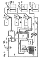
このセクションは、1つまたは複数の容器から検出用の試験領域に液滴を搬送するための例示的な輸送システム80について記述する;図2を参照されたい。
II. Droplet Transport Overview This section describes an
輸送システム80は、少なくとも1つの容器88によって保持されるエマルジョン86で液滴84を拾い上げるのに、先端部82を利用するように構成される。液滴は、液滴配列領域90で列を成し分離され、次いで試験領域92内を連続的に搬送されて、少なくとも1つの検出ユニット94で液滴の少なくとも1つの態様が検出される。検出ユニットは、試験領域92および/またはその中の流体/液滴を照明するための少なくとも1つの光源96と、照射された試験領域(および/またはその中の流体/液滴)から受信された光を検出するための少なくとも1つの検出器98とを含んでいてもよい。
The
輸送システムは、先端部82に接続されたチャネルネットワーク100を含んでいてもよい。輸送システムは、流体の流れを調節しかつ流体の流れがチャネルネットワーク内に流入させ、流通させ、かつこのネットワークから流出させるために、チャネル形成部材(例えば、チュービングおよび/または1つもしくは複数のチップ)および少なくとも1つの弁(例えば、弁アクチュエータを含んでいてもよい弁102〜106)を含んでいてもよい。チャネルネットワーク100の中、全体、および外への流体の流れは、サンプルポンプ108および希釈ポンプ110などの少なくとも1つのポンプによって駆動することができる。チャネルネットワーク100内に導入された流体は、エマルジョン86と、リザーバ114によって形成されかつポンプの1つまたは複数に動作可能に接続された1つまたは複数の流体供給源112とによって供給することができる(洗浄流体を、先端部を介して導入してもよい。)。各流体供給源は、システムのエマルジョンおよび/または担体相の連続相に対して混和性があってもよいが液滴の分散相ではない、疎水性流体(例えば、油)などの任意の適切な流体を提供することができ、または、チャネルネットワークおよび/または先端部の洗浄部分に、比較的より親水性の高い流体を提供することができる。試験領域92内を移動する流体は、1つまたは複数の廃棄物受容器116に収集することができる。
The transportation system may include a
チャネルネットワークは、複数のチャネルを含む任意の流体工学アセンブリにすることができる。チャネルネットワークは、チャネル(例えば、チュービング、チップなどにより形成される。)、1つまたは複数の弁、1つまたは複数のチャンバ、1つまたは複数の圧力源、流体供給源などの、任意の組合せを含むことができる。 The channel network can be any fluidic assembly that includes multiple channels. A channel network is any combination of channels (eg, formed by tubing, tips, etc.), one or more valves, one or more chambers, one or more pressure sources, fluid sources, etc. Can be included.
連続相、担体流体、および/または希釈流体は、水に対して非混和性である任意の液体(または液化可能な)化合物または液体化合物の混合物を含んでいてもよい、油または油相と呼ぶことができる。油は、合成されたものでも天然に生ずるものでもよい。油は、炭素および/またはケイ素を含んでも含んでいなくてもよく、水素および/またはフッ素を含んでも含んでいなくてもよい。油は、親油性でも疎油性(lipophobic)であってもよい。言い換えれば、油は、有機溶媒に対して一般に混和性であっても非混和性であってもよい。例示的な油には、とりわけ、少なくとも1種のシリコーン油、鉱油、フルオロカーボン油、植物油、またはこれらの組合せを含めることができる。例示的な実施形態において、油は、過フッ化有機溶媒であってもよいフルオロカーボン油などのフッ素化油である。フッ素化油は、典型的には水素の代わりに用いられるフッ素を含む。フッ素化油は、ポリフッ素化されていてもよく、すなわちこの油は、とりわけ、5個超または10個のフッ素など多くのフッ素を含むことを意味する。フッ素化油は、さらにまたは代替として過フッ化されていてもよく、すなわちほとんどのまたは全ての水素がフッ素で置換されていることを意味する。油相は、1種または複数の界面活性在を含んでいてもよい。 The continuous phase, carrier fluid, and / or diluent fluid is referred to as an oil or oil phase, which may include any liquid (or liquefiable) compound or mixture of liquid compounds that are immiscible with water. be able to. The oil may be synthetic or naturally occurring. The oil may or may not contain carbon and / or silicon, and may or may not contain hydrogen and / or fluorine. The oil may be lipophilic or lipophobic. In other words, the oil may be generally miscible or immiscible with the organic solvent. Exemplary oils can include at least one silicone oil, mineral oil, fluorocarbon oil, vegetable oil, or combinations thereof, among others. In an exemplary embodiment, the oil is a fluorinated oil, such as a fluorocarbon oil, which may be a perfluorinated organic solvent. Fluorinated oils typically contain fluorine that is used in place of hydrogen. The fluorinated oil may be polyfluorinated, i.e. the oil is meant to contain many fluorines, such as more than 5 or 10 fluorines, among others. Fluorinated oils may additionally or alternatively be perfluorinated, meaning that most or all of the hydrogen is replaced with fluorine. The oil phase may contain one or more surfactants.
各ポンプは、流体の流れを駆動することが可能な、任意の適切な構造を有することができる。ポンプはとりわけ、例えばシリンジポンプなどの容積式ポンプであってもよい。その他の例示的なポンプには、蠕動ポンプまたはロータリーポンプなどが含まれる。 Each pump can have any suitable structure capable of driving a fluid flow. The pump may in particular be a positive displacement pump, for example a syringe pump. Other exemplary pumps include peristaltic pumps or rotary pumps.
先端部82の位置は、この図示における3つの直交軸120など、1つまたは複数の軸に沿って、先端部および容器88の相対運動をもたらすことが可能な駆動アセンブリ118によって決定することができる。言い換えれば、駆動アセンブリは、とりわけ、容器を静止させたまま先端部を動かすことができ、先端部を静止させたまま容器を動かすことができ、または先端部および容器の両方を同時にまたは異なる時に動かすことができる。いくつかの実施形態では、駆動アセンブリは、各容器(例えば、マルチウェルプレートの各ウェル)に位置合わせした状態で先端部を動かし、容器内で流体に接触させた状態で先端部を低下させ、かつ容器の上方に先端部を上昇させて、先端部を別の容器に移動させることが可能である。駆動アセンブリは、先端部/容器の移動を駆動するための1つまたは複数のモータと、先端部および/または容器の現在位置を決定しかつ/または先端部/容器の位置を変更するための1つまたは複数の位置センサとを含むことができる。したがって、駆動アセンブリは、フィードバックループにおいて先端部の位置の制御を行うことができる。
The position of the
輸送システム80は、さらに、制御器122を含んでいてもよい。制御器は、とりわけ、検出ユニット94、弁102〜106(例えば、それらのアクチュエータを介して)、ポンプ108および110、および駆動アセンブリ118などの輸送システムの、任意のその他の構成要素の操作を制御し、この構成要素からの入力を受け取り、かつ/またはその他の方法でこの構成要素と連絡することができる。例えば、制御器は、光源の動作を制御しかつ発生した光の強度をモニタし、検出器の感度を調節し(例えば、利得を調節することによって)、検出器から受信した信号を処理する(例えば、液滴を特定し標的濃度を評価するために)などすることができる。制御器は、さらにまたは代替として、弁の位置、先端部の動き(したがって、先端部の位置)、ポンプの動作(例えば、ポンプの選択、流れの方向(すなわち、陽圧または陰圧の発生)、流量、計量分配される体積など)を制御することができる。したがって制御器は、流体がチャネルネットワーク100内をいつ、どこで、かつどのように移動するかを、制御することができる。制御器は、任意の適切な操作または操作の組合せの自動化を、提供することができる。したがって輸送システムは、使用者が支援または介入することなく、自動的に複数のエマルジョンを導入し試験するように構成することができる。
The
制御器は、システム機能の整合的な動作および制御を実現するために、電子構成要素の任意の適切な組合せを含むことができる。電子構成要素は、1カ所に配置することができ、またはシステムの異なる領域に分布させることができる。制御器は、データ処理のために1つまたは複数のプロセッサ(例えば、中央/コンピュータ処理装置(CPU)とも呼ばれるデジタルプロセッサ)を含んでいてもよく、スイッチ、増幅器、フィルタ、アナログ-デジタル変換器、バス、1つまたは複数のデータ記憶装置など、プロセッサを支援しかつ/または補うために追加の電子構成要素を含んでいてもよい。ある場合には、制御器は、複数の下位制御装置と連絡する少なくとも1つのマスター制御装置を含んでいてもよい。ある場合には、制御器は、デスクトップまたはラップトップコンピュータを含んでいてもよい。制御器は、ディスプレー、キーボード、タッチスクリーン、マウスなどの任意の適切なユーザインターフェースに接続されていてもよい。 The controller can include any suitable combination of electronic components to achieve consistent operation and control of system functions. The electronic components can be placed in one place or distributed in different areas of the system. The controller may include one or more processors (e.g., a digital processor, also called a central / computer processing unit (CPU)) for data processing, such as switches, amplifiers, filters, analog-to-digital converters, Additional electronic components may be included to assist and / or supplement the processor, such as a bus, one or more data storage devices. In some cases, the controller may include at least one master controller in communication with a plurality of subordinate controllers. In some cases, the controller may include a desktop or laptop computer. The controller may be connected to any suitable user interface such as a display, keyboard, touch screen, mouse.
チャネルネットワーク100は、液滴が先端部82から廃棄物受容器116に移動するときに液滴を受容する、複数のチャネルまたは領域を含んでいてもよい。「チャネル」という用語は、下記の説明および実施例において、「ライン」という用語と同義に使用されることになる。
先端部82は、先端部82からチャネルネットワーク100内に延びる、吸込みチャネルまたは取り込みチャネル130の部分を形成することができる。液滴は、取りこみチャネル130から、チャネルネットワークのその他の領域に進入することができる。エマルジョン86中の液滴84は、任意の適切な能動的または受動的メカニズムによって、先端部82を介して(すなわち、先端部によって拾い上げられる。)取りこみチャネル130内に取り込むことができる。例えばエマルジョン86は、とりわけ、ポンプによって作り出された陰圧によって、すなわち吸引(吸込みとも呼ばれる。)によって、取り込みチャネル内に引き入れることができ、容器88内のエマルジョン86に加えられた陽圧によって導入チャネル内に押し出すことができ、毛管作用によって取り込みチャネル内に引き入れることができ、またはこれらの組合せが可能である。
The
例示的な実施形態では、ポンプ108が、陰圧を加えることによってエマルジョンを取り込みチャネル130に引き入れる。取り込みを実現するために、弁102を、132で仮想的に示した取り込み位置に配置して、先端部82とポンプ108との間を流体連通させることができる。次いでポンプは、先端部をエマルジョンに接触させた状態で、134の仮想液滴によって示されるエマルジョンを、先端部82を介して取り込みチャネル130内に引き入れることができる。ポンプは、取り込まれた液滴を、弁102を介して保持チャネル136内に引き入れることができる。
In the exemplary embodiment, pump 108 draws the emulsion into
取り込まれた液滴は、この液滴を保持チャネル136から弁102を通して待機チャネル138内に運ばれることにより、検出ユニット94に向かって移動することができる。待機チャネルは、液滴を、140で示される単一ファイルに配置することができる。
The captured droplet can be moved toward the
液滴は、待機チャネル138から出現するときに、任意選択で単一ファイルとして合流領域または分離領域142に進入することができる。合流領域は、待機チャネルと少なくとも1つの希釈チャネル144との接合部に形成することができる。希釈チャネルは、液滴および担体流体/連続相148が待機チャネル138からの流れとして合流領域に進入するときに、合流領域142を通り抜けた希釈流体146の流れを供給することができる。希釈流体は、担体流体に対して混和性であってもよく、液滴が配置されたエマルジョンを局所的に希釈する働きをし、それによって、液滴間の平均距離を増大させることにより液滴が分離される。
As the droplet emerges from the
液滴は、合流領域142を離れた後、試験チャネル150に進入することができる。試験チャネルは、この試験チャネルを照明することができかつ試験領域からの光を検出することができる、試験領域92を含んでいてもよい。
The droplet can enter the
先端部82は、一連のエマルジョンを異なる容器から取り込むのに、利用することができる。液滴が第1の容器から取り込まれた後、先端部を持ち上げて、存在する場合には容器内の残りの流体との接触を遮断することができる。ある体積の空気を先端部に引き入れて、何組かの取り込まれた液滴同士の間の障壁として働かせることができ、かつ/または液滴がチャネルネットワーク内を移動するときに、離された液滴が遅れないようにすることができる。いずれにしても、先端部は次に、洗浄ステーション152に移動することができ、先端部82を洗い流し、濯ぎ、および/または浸漬によって洗浄することができる。より具体的には、流体は、洗浄ステーションで先端部から計量分配することができかつ/または先端部に引き入れることができ、この先端部は、洗浄(例えば、汚染除去)中に洗浄ステーションで流体154と接触させて配置してもしなくてもよい。次いで洗浄された先端部を、別の容器と位置合わせしかつ別容器内まで低下させることにより、別のエマルジョンを取り込むことが可能になる。
The
輸送システムは、とりわけ、少なくとも1種のエマルジョンを保持するための少なくとも1つの容器(すなわち、容器)(および/または、一揃いのエマルジョンを保持するための一組の容器)、エマルジョンに接触しこのエマルジョンから液滴を受容するための少なくとも1つのピックアップ先端部、陽圧および/または陰圧を発生させるための1つまたは複数の流体駆動メカニズム(すなわち、流体を先端部の内部に引き入れかつ/または先端部の外に押し出し、かつ/または流体を検出部位に通すための、1つまたは複数のポンプ)、先端部および/または容器の位置決めメカニズム(先端部を容器に対して移動させるため、またはその逆を行うため)、流路を選択し変更するための1つまたは複数の弁、検出用に液滴を受容するための少なくとも1つの試験領域、またはこれらの任意の組合せを含むことができる。 The transport system includes, among other things, at least one container (i.e., container) for holding at least one emulsion (and / or a set of containers for holding a set of emulsions) in contact with the emulsion. At least one pickup tip for receiving droplets from the emulsion, one or more fluid drive mechanisms for generating positive and / or negative pressure (i.e., drawing fluid into the tip and / or One or more pumps to push out of the tip and / or to pass fluid through the detection site), tip and / or container positioning mechanism (to move the tip relative to the container or One or more valves for selecting and changing flow paths, at least one test area for receiving droplets for detection Or it may include any combination thereof.
静止/バッチ形態で容器内で行われる液滴反応、液滴輸送システム、および検出システムの、これらおよびその他の態様は、相互参照の下で上記列挙されかつ参照により本明細書に組み込まれる特許文献でさらに詳述される。 These and other aspects of droplet reaction, droplet transport system, and detection system performed in a vessel in stationary / batch form are listed above and incorporated herein by reference, under cross-reference. Will be described in more detail.
(III.実施例)
下記の実施例は、液滴を検出するための液滴輸送システムの、選択された態様および実施形態について記述する。これらの実施例は、単なる例示を目的とし、本発明の開示の全範囲を定義または制限すべきではない。
(III. Examples)
The following examples describe selected aspects and embodiments of a droplet transport system for detecting droplets. These examples are for illustrative purposes only and should not define or limit the full scope of the disclosure.
(実施例1)
2状態マルチポート弁を備えた例示的な輸送システム
この実施例は、3つのポンプにより利用される二組のチャネル接続間での切換えを可能にする、2状態(すなわち、2構成)マルチポート弁を備えた例示的な液滴輸送システムについて記述する;図3および4を参照されたい。
(Example 1)
Exemplary transport system with a two-state multiport valve This example is a two-state (ie, two-configuration) multiport valve that allows switching between two sets of channel connections utilized by three pumps An exemplary droplet transport system is described; see FIGS. 3 and 4.
図3は、図2の液滴輸送システム80の例示的な実施形態170を示す。輸送システム170は、その他の輸送システムに関して本明細書で開示される構成要素および特徴の、任意の組合せを含むことができる。
FIG. 3 shows an
輸送システム170は、輸送システム80に関して既に述べたように一般に動作し、以下に述べる場合を除いてシステム170の対応物要素は同様に機能し、これらにはシステム80の場合と同じ符号を割り当てる。
The
エマルジョンは、個々のエマルジョン86に容器88(すなわち、ウェル)を提供するマルチウェルプレート172によって、保持することができる。各エマルジョンの液滴は、例えば、輸送システム170に取り込む前にバッチとして熱サイクルに供することができる。熱サイクリングは、エマルジョンをプレート172により保持した状態で行った可能性もあり、またはエマルジョンは、熱サイクリングまたはその他の適切なインキュベーションが行われた後に、プレートに輸送することができる。
Emulsions can be held by a
システム170には、マルチポート弁174を備えることができる。弁は、少なくとも4、6、8、または10個などの複数のポートを有し、そこにチャネルネットワーク100のチャネルを接続することができる。例えば、この場合、弁174は、1から10まで連続して標識された10個のポート176を有する。この図示におけるポート4および7などのポートのいくつかは栓が閉められる可能性があるが、システムに機能性を付加するために、必要に応じて追加のチャネルの接続を行うことが可能である。
The
弁174は、多重状態または多重構成の弁、少なくとも2状態/構成として記述することができる。各構成において、弁は、1対または複数対のチャネルを、互いに対をなして流体連通するように配置することができる。この場合、弁174は、2つの構成が「A」および「B」として標識されている、2状態弁として構成される。構成Aでは、隣接する対のポート、すなわちポート2および3、4および5、6および7、8および9は、対ごとに流体連通している。ポートは、円形に配置することができ(例えば、実施例5参照)、したがってポート10および1も流体連通している。構成Bでは、対の形成が1つずれ、すなわちポートの下記の対が、流体連通している; 1および2、3および4、5および6、7および8、9および10。
The
チャネルネットワーク100のチャネルは、チュービング176の小片によって実質的にまたは少なくとも優位に画定することができる。チュービングの各小片は、毛管チュービングであってもなくてもよい(すなわち、とりわけ約2または1mm未満の内径を有する。)。チュービングの2つ以上の端部178は、調節可能な構成にある弁174によって互いに接続することができ、またはコネクタ180を使用して固定構成に接続することができる(チャネルが交わる場所を四角形として示す。)。各コネクタは、チュービングチャネルに連絡するコネクタチャネルを画定することができる。また、各コネクタは、各コネクタチャネルに位置合わせされかつチュービングの端部を受容するようにサイズが決められた、カウンタボアを画定することもできる。継手は、チュービングの小片がコネクタに固定されるように、コネクタに係合させることができる。
The channels of the
コネクタ180の少なくとも1つは、試験前にエマルジョンを希釈するために、セパレータまたはシンギュレータ(singulator)とも呼ばれるスペーサ182を形成してもよい。この場合、スペーサ182は、2つの希釈チャネル144と1つの待機チャネル138とが合流領域142を形成して、分離した液滴を試験チャネル150に供給する、十字形を有している。その他の場合には、スペーサは、ただ1つの希釈チャネル(例えば、T字形スペーサ)または3つ以上の希釈チャネルを有する。
At least one of the
輸送システム170は、下記の通り動作することができる。弁174を構成Aに配置して、ポート1および10を接続し、取り込みチャネル130と保持チャネル136との間を流体連通させることができる。サンプルポンプ108を操作して陰圧を発生させることができ、それによってエマルジョン86を、ウェル88から先端部82および取り込みチャネル130を通して保持チャネル136内に引き入れる。次いで弁174を構成Bに配置してポート9および10を接続することができ、保持チャネル136と待機チャネル138との間が流体連通される。ポンプ108を再び操作するが、この場合は陽圧を発生させることができ、エマルジョン86を保持チャネル136から待機チャネル138に押し出す。
The
エマルジョンの液滴がスペーサ182に到達する前に、希釈ポンプ110を操作して陽圧を発生させることができ、希釈流体146を希釈チャネル144内に通してスペーサ182まで押し出す。その結果、エマルジョンは、液滴がスペーサの合流領域142に進入するときに、希釈流体によって希釈される。次いで分離された液滴は、試験チャネル150に沿って移動し、検出用の試験領域92を通って、廃棄物ライン184に進入する。
Before the emulsion droplets reach the
廃棄物ライン184は、ポート5がポート6に接続されているので、弁174がその現行の構成、すなわち構成Bにある場合、廃棄物受容器116に流体連通している。したがって、ポンプ108からの連続的な陽圧によって、液滴をウェルライン184から、弁174のポート5および6を通して、廃棄物受容器内に押し出す。
システム170は、第3のポンプ、すなわち洗浄ポンプ190を含んでいてもよく、このポンプは、希釈流体146と同じであっても異なっていてもよい洗浄流体191で、チャネルを洗い流すことにより、清浄能力を提供する。チャネルネットワーク100は、弁174が取り込み構成(構成A)または試験構成(構成B)にある場合、ポンプ190によってバックフラッシングが可能になるよう構成することができる。この場合、ポンプ190は、構成Aの弁174でバックフラッシュすることができる。ポンプは、洗浄流体191を、第1のバックフラッシュチャネル192、ポート2および3、第2のバックフラッシュチャネル194に通し、試験チャネル150および待機チャネル138に通し、最後にポート8および9を介して廃棄物受容器に押し出す。このように洗浄ポンプ190は、流体の流れを、チャネル138および150に通して逆向きに駆動する。この逆流は、異なるエマルジョンによる取り込みおよび試験の別のサイクルの前に、これらのチャネルから残留する液滴を全て除去するよう働くことができ、かつ/または、スペーサ182の場合のように流路が最小直径を有する場合、収集または形成される可能性のある細片および/または詰まりを除去することができる。
The
サンプルポンプ108は、構成Aの弁174で洗浄するために操作してもよい。ポンプは、油などのフラッシング流体を、保持チャネル136、ポート10および1、取り込みチャネル130、および先端部82に通して押し出すことができる。このバックフラッシングは、プレートの洗浄ステーションおよび/またはウェル上に配置された先端部82で行うことができる。
図4は、図2の液滴輸送システム80の、別の例示的な実施形態210を示す。輸送システム210は、その他の輸送システムに関して本明細書で開示される構成要素と特徴との任意の組合せを含むことができる。
FIG. 4 shows another
輸送システム210は、輸送システム170に関して既に述べたように一般に動作し、以下に述べる場合を除いてシステム210の対応物要素は同様に機能し、これらにはシステム170の場合と同じ符号を割り当てる。しかし、システム210は、十字のスペーサ182(図3参照)の代わりにT字形スペーサ212によって形成された、液滴配置領域90を含む。
The
システム210は、構成Aの弁174で、液滴を取り込みチャネル130および保持チャネル136内に引き入れるのに、サンプルポンプ108を使用することができる。弁174を構成Bに変えた後、サンプルポンプ108は、取り込まれたエマルジョンを待機チャネル138に通してスペーサ212に押し出すことができる。希釈ポンプ110は、希釈流体146を一斉に押し出してスペーサに通し、検出ユニット94で検出するための、間隔を空けて配された一連の液滴を形成することができる。試験領域92通過後、液滴は、廃棄物ライン184に前進し、最後に弁ポート7および8を介して廃棄物受容器116に進むことができる。
The
次いで弁174を、洗浄のため元の構成Aに配置することができる。サンプルポンプ108は、流体を取り込みチャネル130に通して先端部82から押し出すことができ、洗浄ポンプ190は、流体を、チャネル192、194、および150内に押し出すことができる。
The
(実施例2)
同軸先端部を備えた例示的な輸送システム
この実施例は、同軸先端部を備えた例示的な液滴輸送システムについて記述する;図5〜9を参照されたい。
(Example 2)
Example Transport System with Coaxial Tip This example describes an exemplary droplet transport system with a coaxial tip; see FIGS.
図5は、図2の液滴輸送システム80の、例示的な実施形態240を示す。輸送システム240は、その他の輸送システムに関して本明細書で開示された構成要素および特徴の、任意の組合せを含むことができる。輸送システム240は、輸送システム80および170に関して既に述べたように一般に動作し、以下に述べる場合を除いて対応物要素は同様に機能し、これらには同じ符号を割り当てる。しかし、システム240は、同軸先端部242など、以下に記述されるいくつかの新しい構成要素および特徴を組み込むことができる。
FIG. 5 shows an
図6は、先端部242を含む流体工学アセンブリ244を示し、このアセンブリは、駆動アセンブリ118のアーム246によって支持されている。先端部242は、同軸上に配置された内部チューブ248および外部チューブ250を含んでいてもよい。内部チューブ248は、外部チューブ250の下端から突出して、ノーズ252を形成することができる。ノーズは、とりわけ約0.2から2cmなど、任意の適切な長さを有していてもよい。内部チューブ248および外部チューブ250は、それぞれ、同軸にある内部チャネル254および外部チャネル256を画定する。
FIG. 6 shows a
流体工学アセンブリ244は、先端部242の同軸チャネル254、256と、チャネルネットワークのそれぞれのチャネル(図5参照)、すなわち計量分配チャネル260および取り込みチャネル130との間に個別の流体工学接続を形成する相互接続258を含んでいてもよい。チャネル260および130は、それぞれのチュービング部材262、264によって画定することができる。各チュービング部材の端部は、相互接続258のボアに受容され、継手266で相互接続に固定することができる。先端部242の上端も、相互接続258のボアに受容され、所定位置に固定することができる。
The
2つの個別の流体接続は、下記の通りである:先端部242の外部チャネル256が、相互接続十字チャネル268を介して計量分配チャネル260に流体連通し、先端部の内部チャネル254が取り込みチャネル130に流体連通する。
The two separate fluid connections are as follows: the
図7は、内部チューブ248のノーズ252の下部セクションがエマルジョン86に浸漬されている、流体工学アセンブリ244を示す。外部チューブ250は、エマルジョンに接触していない。したがってエマルジョンは、エマルジョンを外部チューブに接触させることなく(または汚染することなく)、内部チューブで拾い上げることができる。
FIG. 7 shows a
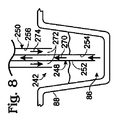
図8は、エマルジョン86が先端部によって拾い上げられるときの、先端部242のチャネル254、256を通した流体の流れの例示的な方向を、概略的に示す。エマルジョンは、270の流れの矢印により示されるように、内部チューブ248内に引き入れることができる。対照的に、担体流体(または希釈流体)272は、274の対向する流れの矢印によって示されるように、外部チューブ250から計量分配することができる。担体流体は、エマルジョンの取込みに対して任意の適切な時間に計量分配することができる。例えば、担体流体は、エマルジョンの取込みと同時に計量分配することができ、1つもしくは複数の重なり合った時間間隔の間に計量分配することができ、1つもしく複数の重なり合っていない時間間隔の間に計量分配することができ(例えば、取込みの間交代で)、またはこれらの同様のことを行うことができる。
FIG. 8 schematically illustrates an exemplary direction of fluid flow through the
図9は、先端部が洗浄ステーション152で洗浄されるときの、先端部242のチャネル254、256を通した流体の流れの例示的な方向を、概略的に示す。この場合、流体は、276の流れの矢印によって示されるように、先端部の内部チューブ248および外部チューブ250内を同じ方向に流れる。
FIG. 9 schematically illustrates an exemplary direction of fluid flow through the
内部チューブ内を流れる流体は、残留液滴を全てチューブから洗い流し、外部チューブ内を流れる流体は、278の流体によって示されるように、ノーズ252の外側を濯ぐ。ノーズは、この洗浄の手順中、洗浄ステーション内の流体全てと接触しなくてよい。あるいは、先端部の任意の適切な部分は、洗い流し、濯ぎ、または浸漬操作中、洗浄流体に浸漬させることができる。
Fluid flowing in the inner tube flushes any residual droplets from the tube, and fluid flowing in the outer tube rinses outside the
図5は、エマルジョンのピックアップおよび先端部の洗浄のために、同軸先端部242の使用を可能にした、流体工学レイアウトを示す。1対のポンプ290、292は、エマルジョンの取り込みおよび液滴の試験中、協働して機能することができる。ポンプのそれぞれは、ベントフィルタ298を備えた容器296によって保持された、油などの希釈流体246の同じ供給源294に、動作可能に接続することができる。第3のポンプ、すなわち洗浄ポンプ300は、洗浄流体302の供給源に動作可能に接続することができる。
FIG. 5 shows a fluidics layout that allows the use of a
ポンプ290、292は、構成Bの弁174と閉じた廃棄物チャネル184とによって、エマルジョン86を取り込むことができる。廃棄物チャネル内の流体の流れは、ソレノイド弁304などの任意の適切な弁、または弁174への適切な接続によって、遮断することができる。弁174および304によってまとめて提供された弁の構成によれば、ポンプ290は、エマルジョン86を、先端部242の内部チューブを介して取り込みチャネル130内に、さらに弁174のポート1および2を通って、保持チャネル136内に引き入れることができる。ポンプ292は、計量分配チャネル260および先端部242の外部チューブから流出させるため、ポート10および9を通して上流チャネル306から圧力を加えることによりウェル88内の先端部242の内部チューブによる取込みが行われるように、希釈流体246を計量分配することができる。
ポンプ290、292は、液滴を分離するようにかつ分離された液滴を試験領域92内に通すように、協働する。システム240の弁構成は、構成Bに弁174を切り換え、かつソレノイド弁304を開放することにより廃棄物ライン184を開放することによって、変更することができる。ポンプ292は、エマルジョンを保持チャネル136からスペーサ182に押し通すことができ、一方ポンプ290は、希釈流体をスペーサ内に押し通す。したがって液滴は、別の弁を通過することなく保持チャネル136から待機チャネル138に移動し、試験領域を通る。弁は、液滴の完全性を崩壊させる可能性があるので、弁内の通過を減少させるためのシステム240での流体工学の革新的な使用は、アッセイ性能を改善することができる。いずれにせよ、ポンプ290、292からの陽圧により作り出された、組み合わされた流れは、試験チャネル150、廃棄物チャネル184、および廃棄物受容器116を通って、分離された液滴を運ぶことができる。
取り込みチャネル130、計量分配チャネル260、および先端部242を、エマルジョンの取り込みおよび/または液滴の試験の後に、洗浄することができる。先端部は、洗浄前に洗浄ステーション152に移動してもよい。洗浄は、希釈流体246および/または洗浄流体302で行うことができる。例えば、チャネル130、260、および先端部242は、希釈流体のみで、洗浄流体のみで、または希釈流体と洗浄流体との組合せで、連続してまたは交代でなどによって、洗浄することができる。希釈流体246による洗浄は、取り込みチャネル136内へのエマルジョンの取り込みに関して既に述べたものと同じ弁構成を使用して、実現することができる。特に、弁174は構成Bに配置することができ、ソレノイド弁304は閉じ、希釈流体は、ポンプ290、292により加えられた陽圧に応答して、チャネル130、260内と、先端部の内側チャネル254および外部チャネル256に押し通される(例えば、図9を参照されたい。)。対照的に、洗浄流体302による洗浄は、弁174を構成Aに配置し、洗浄ポンプ300で洗浄チャネル308、310に陽圧を加えることによって、実現することができる。チャネル308、310は、ポート2および3、ポート8および9をそれぞれ介してチャネル130、260に接続する。その結果、洗浄ポンプ300によって加えられた陽圧は、チャネル130、260が油またはその他の希釈流体でフラッシュされた後、チャネル130、260に伝達され、洗浄流体を先端部の両チャネル254、256から追い出す(例えば、図9参照)。
洗浄ステーション152で収集された廃棄物流体は、図5において概略的に示される蠕動ポンプ314などのポンプによって、排出ライン312内を廃棄物受容器116に通り抜けることができる。蠕動ポンプは、洗浄ステーションを空にするため連続的にまたは断続的に動作することができる。
Waste fluid collected at the cleaning
洗浄流体302は、希釈流体246とは異なる化学組成を有していてもよい。例えば、洗浄流体は、希釈流体よりも親水性および/または極性が高くても良い。より親水性/極性の高い洗浄流体の使用は、残留液滴の除去でより効率的にすることができるが、それは液滴の分散相が、希釈流体よりも洗浄流体においてより可溶性があると考えられるからである。洗浄流体は、希釈流体において少なくとも部分的に可溶性があるとも考えられ、その逆も同様であるので、洗浄流体によって希釈流体をチャネルから除去することが可能であり、またその逆も同様である。例示的な洗浄流体は、とりわけ、低分子量のものであってもよい(例えば、約500ダルトン未満の分子量)アルコールやケトンなどの有機溶媒を含んでいてもよい。適切なアルコールは、エタノールおよびイソプロパノールを含んでいてもよく、適切なケトンは、とりわけアセトンを含んでいてもよい。洗浄流体は、水を含んでいてもいなくてもよい。洗浄流体中の水の例示的な濃度には、とりわけ、約0から50%、5から40%、または10から30%が含まれる。洗浄流体の使用は、取り込みおよび計量分配チャネル130、260、および先端部242を洗浄するのに必要な希釈流体の量を、低減することができる。例えば、いくつかの実施形態では、油の消費を1ウェル当たり約1.75mLから1ウェル当たり約0.4mLに低減させることができ、それと共にコストが節約される。あるいは、またはさらに、洗浄流体の使用は、その他のエマルジョンの後続の試験でキャリーオーバー(例えば、残留液滴による汚染)を低減させまたは事実上なくすことができる。洗浄流体は、同軸先端部で見出された汚染を除去することができ、かつ/または洗浄ステーションでの詰まりを溶解することができる。油の消費および汚染の低減は、サンプル処理効率を上昇させることができ、例えば、ピックアップ先端部の完全な洗浄によって、2相ピックアップからの汚染を低減させることができ、拾い上げることができかつ処理できる液滴の数が増加し、スループットは、液滴の分離および試験中に第3のポンプにより先端部を洗い流すことによって、増大させることができる。70%エタノールなどのいくつかの適切な洗浄流体は、標準的に蓄えられ、液滴アッセイを行う可能性のある生物学実験室などの実験室で利用可能である。やはり70%エタ
ノールなどのいくつかの洗浄流体は、出力ラインおよび廃棄物受容器での微生物増殖を軽減することができ、希釈油を、増殖を防止するのに必要なまたは望ましいと考えられる任意の追加の抗カビ剤から分離することができる。エタノールは、2相の問題および水溶性の汚染を低減させることができまたはなくすことができるHFEなどの様々なフルオロカーボン油に混和性であってもよい(HFEのみではそうではないと考えられる。)。
The cleaning
取り込みチャネル136、待機チャネル138、および試験チャネル150は、エマルジョンからの一組の液滴を試験した後に洗浄してもよい。洗浄は、弁174を構成Aに配置し、ソレノイド弁304を開放し、ポンプ292で上流チャネル306に陽圧を加えることによって、流体を取り込みチャネル136から試験チャネル150に通して廃棄物チャネル184、および廃棄物受容器116まで運ぶことによって行うことができる。
(実施例3)
液滴輸送システムを使用するための例示的な手順
この実施例は、とりわけ実施例2のシステムなどの液滴輸送システムの使用に関する、例示的な手順およびその他の課題について記述する。これらの手順は、下記の種類の操作、すなわち: (A)プリプレート(pre-plate)処理、(B)ウェル処理、(C)ポストプレート(post-plate)処理、および(D)特殊な操作を含むことができる。
(Example 3)
Example Procedure for Using a Droplet Transport System This example describes an example procedure and other issues, particularly with respect to the use of a droplet transport system, such as the system of Example 2. These procedures consist of the following types of operations: (A) pre-plate processing, (B) well processing, (C) post-plate processing, and (D) special operations Can be included.
A.プリプレート処理
第1のウェル(または容器)が処理される前に、下記の操作を実行することができる:
A. Preplate processing Before the first well (or container) is processed, the following operations can be performed:
検出器の起動。検出器の性能は、温度に敏感であると考えられる。例えば、検出器LEDの色のスペクトルは、温度と共に変わる可能性がある。LEDは、使用中に熱を放出し、安定な動作温度を実現するのに昇温期間を必要とする可能性がある。LEDは、ウェルを処理する前に温度および色のスペクトルが確実に安定になるように、ウェルの処理に先立って点灯することができる。 Start the detector. The performance of the detector is considered temperature sensitive. For example, the color spectrum of the detector LED can change with temperature. LEDs can dissipate heat during use and require a warm-up period to achieve a stable operating temperature. The LED can be lit prior to processing the well to ensure that the temperature and color spectrum is stable before processing the well.
ポンプの初期化。このシステムは、始動時には未知の状態にある可能性があるので、ポンプを初期化してシステムを既知の状態にする。ポンプ(例えば、サンプルポンプ、油または希釈ポンプ、廃棄物または蠕動ポンプなど)は、初期化して定位置にすることができる。ポンプは、特定の体積の油が充填されるように初期化することができる。ポンプは、単一パッケージに統合された弁を有していてもよく;ポンプの弁は、既知の位置に初期化することができる。 Pump initialization. Since this system may be in an unknown state at startup, the pump is initialized to bring the system to a known state. Pumps (eg, sample pumps, oil or dilution pumps, waste or peristaltic pumps, etc.) can be initialized to a home position. The pump can be initialized to be filled with a specific volume of oil. The pump may have a valve integrated in a single package; the pump valve can be initialized to a known position.
試験領域およびスペーサフラッシュ。試験領域のチュービングおよびスペーサは、初期の使用による残留サンプルまたは砕片を除去するために、ある体積の油でフラッシュすることができる。試験領域のチュービングおよびスペーサをフラッシュするために、サンプルおよび油(例えば、希釈)ポンプにそれぞれ、油リザーバからのある体積の油を充填することができる。ポンプの充填後、検出器の排出(ソレノイド)弁を開位置に構成することができ、マルチポート弁を、サンプルポンプとスペーサとが接続されるように構成することができる。次いでサンプルおよび油のポンプは、油を放出して、試験領域のチュービングおよびスペーサをフラッシュし、廃棄することができる。試験領域のチュービングおよびスペーサは、多数回フラッシュしてもよい。 Test area and spacer flash. The test area tubing and spacers can be flushed with a volume of oil to remove residual samples or debris from initial use. To flush the test area tubing and spacers, the sample and oil (eg, dilution) pumps can each be filled with a volume of oil from the oil reservoir. After pump filling, the detector discharge (solenoid) valve can be configured in the open position, and the multiport valve can be configured such that the sample pump and spacer are connected. The sample and oil pump can then release the oil to flush and discard the test area tubing and spacers. The test area tubing and spacers may be flushed multiple times.
サンプルピックアップ(同軸)先端部のフラッシュおよび濯ぎ。サンプルピックアップ先端部は、初期の使用による残留サンプルまたは砕片を除去するために、ある体積の油でフラッシュ(内部洗浄)し濯ぐ(外部洗浄)ことができる。サンプルピックアップ先端部をフラッシュし濯ぐために、サンプルおよび油のポンプをそれぞれ、油リザーバからのある体積の油で充填することができる。ポンプの充填後、サンプルピックアップ先端部を、洗浄ステーション(または、廃棄物ウェル)上に位置決めすることができる。検出器排出弁は、閉位置に構成することができ、マルチポート弁は、サンプルポンプとピックアップ同軸チューブの外部チャネルとが、かつ油ポンプとサンプルピックアップ先端部とが接続されるように構成することができる。次いでサンプルポンプは、ピックアップ同軸チューブの外部チャネルを通して油を放出することにより、サンプルピックアップ先端部を濯ぐことができ、油ポンプは、サンプルピックアップ先端部を通して油を放出することにより、サンプルピックアップ先端部をフラッシュすることができる。洗い流しおよび濯ぎからの油は、洗浄ステーションに流入する。廃棄物(例えば、蠕動)ポンプは、油を洗浄ステーションから廃棄物リザーバに輸送して、洗浄ステーションから溢れるのを防止することができる。サンプルピックアップ先端部は、多数回フラッシュし濯いでもよい。 Flush and rinse the tip of the sample pickup (coaxial). The sample pick-up tip can be flushed (internal wash) and rinsed (external wash) with a volume of oil to remove residual samples or debris from initial use. To flush and rinse the sample pick-up tip, the sample and oil pumps can each be filled with a volume of oil from the oil reservoir. After pump filling, the sample pick-up tip can be positioned on the wash station (or waste well). The detector discharge valve can be configured in the closed position, and the multiport valve should be configured so that the sample pump and the external channel of the pickup coaxial tube are connected to the oil pump and the sample pickup tip. Can do. The sample pump can then rinse the sample pick-up tip by releasing oil through the external channel of the pick-up coaxial tube, and the oil pump can discharge the sample pick-up tip by discharging oil through the sample pick-up tip. Can be flashed. Oil from the rinse and rinse flows into the wash station. A waste (eg, peristaltic) pump can transport oil from the wash station to a waste reservoir to prevent overflow from the wash station. The sample pick-up tip may be flushed and rinsed multiple times.
B.ウェル処理
サンプルウェル(例えば、マルチウェルプレートのウェル)中のサンプル(例えば、液滴)の処理中に、下記の操作を実行することができる:
B. Well processing During processing of a sample (e.g., a droplet) in a sample well (e.g., a well of a multi-well plate), the following operations can be performed:
ピックアップ先端部の予備湿潤。サンプルピックアップ先端部の外面を、油で予備的に湿潤させることができる。サンプルポンプに、油リザーバからのある体積の油を充填することができる。マルチポート弁は、サンプルポンプとピックアップ同軸チューブの外部チャネルとが、かつ油ポンプとサンプルピックアップ先端部とが接続されるように、構成することができる。サンプルピックアップ先端部は、洗浄ステーション上に位置決めすることができる。次いでサンプルポンプは、油を洗浄ステーションに放出することができる。廃棄物ポンプは、油を洗浄ステーションから廃棄物リザーバに輸送して、洗浄ステーションから溢れるのを防止することができる。サンプルピックアップ先端部は、多数回、予備的に湿潤させることができる。同様に、油ポンプは、サンプルピックアップ先端部の内面を予備的に湿潤させるのに、使用することができる。 Pre-wetting the pickup tip. The outer surface of the sample pickup tip can be pre-wetted with oil. The sample pump can be filled with a volume of oil from the oil reservoir. The multiport valve can be configured such that the sample pump and the external channel of the pickup coaxial tube are connected, and the oil pump and the sample pickup tip are connected. The sample pick-up tip can be positioned on the cleaning station. The sample pump can then discharge the oil to the wash station. The waste pump can transport oil from the wash station to a waste reservoir to prevent overflow from the wash station. The sample pick-up tip can be pre-wetted multiple times. Similarly, an oil pump can be used to pre-wet the inner surface of the sample pickup tip.
サンプル油の添加。油をサンプルに添加することができる。サンプルポンプには、油リザーバからのある体積の油を充填することができる。マルチポート弁は、サンプルポンプとピックアップ同軸チューブの外部チャネルとが接続されるように構成することができる。サンプルピックアップ先端部は、サンプルを含有するサンプルウェル上に位置決めされてもよい。次いでサンプルポンプは、ピックアップ同軸チューブの外部チャネルを通して油をサンプルウェルに放出することができる。同様に、油ポンプは、サンプルピックアップ先端部を通してサンプルウェルに油を添加するのに使用してもよい。 Add sample oil. Oil can be added to the sample. The sample pump can be filled with a volume of oil from the oil reservoir. The multiport valve can be configured such that the sample pump and the external channel of the pickup coaxial tube are connected. The sample pick-up tip may be positioned on the sample well containing the sample. The sample pump can then discharge oil into the sample well through the external channel of the pickup coaxial tube. Similarly, an oil pump may be used to add oil to the sample well through the sample pickup tip.
サンプルウェルから保持チャネルへのサンプルの輸送。サンプルは、サンプルウェルから保持チャネル(例えば、サンプル保持ループ)に輸送することができる。サンプルの輸送前に、サンプルポンプもしくは油ポンプのいずれかまたはそれらの両方に、ある体積の油を予備的に取り込むことができる。ポンプに予備的に取り込まれた体積は、サンプル処理を容易にする任意の体積にすることができる。サンプルポンプおよび油ポンプに予備的に取り込まれた体積は、とりわけ、それぞれ5μLおよび5μLにすることができる。 Transport of sample from sample well to holding channel. The sample can be transported from the sample well to a retention channel (eg, sample retention loop). Prior to sample transport, a volume of oil can be pre-taken into either the sample pump or the oil pump or both. The volume pre-captured in the pump can be any volume that facilitates sample processing. The volume pre-taken into the sample pump and oil pump can be 5 μL and 5 μL, respectively, among others.
サンプルピックアップ先端部は、サンプルウェルに進入することができ、そこでサンプルと流体連通している。サンプルピックアップ先端部は、サンプルのピックアップが効果的になるような、サンプルウェル内のある深さに位置決めしてもよい。サンプルピックアップ先端部は、サンプルウェルの底面から上方に、所定の高さ(例えば、500μm)で位置決めすることができる。 The sample pick-up tip can enter the sample well where it is in fluid communication with the sample. The sample pick-up tip may be positioned at a depth within the sample well so that sample pick-up is effective. The sample pickup tip can be positioned at a predetermined height (for example, 500 μm) above the bottom surface of the sample well.
検出器排出弁は、その閉位置に構成することができ、マルチポート弁は、サンプルポンプとピックアップ同軸チューブの外部チャネルとが、かつスペーサとサンプルピックアップ先端部とが、接続されるように構成することができる。油ポンプは、ある体積を吸引することができ、それによって、サンプルウェルからの流れを、サンプルピックアップ先端部、サンプルピックアップチュービング、マルチポート弁、保持チャネル、スペーサ、油チュービング(例えば、油分配チュービング、油分配T継手(tee)など)に通して油ポンプに向かわせる。吸引速度はサンプルピックアップに効果的な任意の速度にすることができる。サンプルピックアップ速度は、360μL/分であってもよい。油ポンプによって吸引される体積は、サンプルピックアップに有効な任意の体積であってもよい。吸引される体積は、サンプルを、サンプルウェルから中間チュービングに通して保持チャネルにまで移動させるのに十分な体積にすることができる。吸引される体積は、138μLであってもよい。 The detector discharge valve can be configured in its closed position, and the multiport valve is configured such that the sample pump and the external channel of the pickup coaxial tube are connected, and the spacer and the sample pickup tip are connected. be able to. An oil pump can aspirate a volume, thereby diverting the flow from the sample well to the sample pickup tip, sample pickup tubing, multiport valve, retention channel, spacer, oil tubing (e.g., oil dispensing tubing, Pass through oil distribution T joint (tee) and so on to oil pump. The suction speed can be any speed effective for sample pickup. The sample pick-up speed may be 360 μL / min. The volume drawn by the oil pump may be any volume effective for sample pickup. The aspirated volume can be sufficient to move the sample from the sample well through the intermediate tubing to the holding channel. The volume to be aspirated may be 138 μL.
油ポンプによるサンプルの吸引中、サンプルポンプは、サンプルウェルに追加の油を添加することができる。油は、収量(サンプルウェルから回収されたサンプルの量)を増加させるのに使用してもよい。余分な油は、サンプルピックアップに効果的な任意の速度でかつ任意の体積で添加することができる。追加の油は、一度に全てを添加してもよく、または連続的に添加してもよい。それぞれの添加は、独立して、任意の所望の速度および体積で行うことができる。 During sample aspiration by the oil pump, the sample pump can add additional oil to the sample well. Oil may be used to increase yield (amount of sample recovered from sample well). Excess oil can be added at any rate and in any volume effective for sample pickup. The additional oil may be added all at once or may be added continuously. Each addition can be made independently at any desired rate and volume.
油ポンプによるサンプルの吸引中、空気は、サンプルピックアップ先端部に進入することが可能である。サンプルの後に続く空気は、チュービングの壁面に付着しているサンプルの量を減少させることによって、収量を増加させることができる。空気は、ウェル内の液体の体積よりも大きい体積を吸引することによって、サンプルピックアップ先端部に導入することができる。空気は、サンプルの代わりに空気と流体連通するようにサンプルピックアップ先端部を位置決めすることによって、サンプルピックアップ先端部に導入することもできる。 During the suction of the sample by the oil pump, air can enter the sample pickup tip. The air following the sample can increase yield by reducing the amount of sample adhering to the tubing wall. Air can be introduced into the sample pick-up tip by aspirating a volume larger than the volume of liquid in the well. Air can also be introduced into the sample pickup tip by positioning the sample pickup tip in fluid communication with air instead of the sample.
サンプルは、一度に全てが吸引されてもよく、または連続的な吸引ステップとして吸引されてもよい。吸引ステップ間には、時間遅延があってもよい。吸引ステップには、サンプルポンプからの油添加ステップおよび/または空気吸引ステップを挟み込んでもよい。サンプル吸引ステップ、空気吸引ステップ、および油添加ステップの順序は、サンプルウェルから回収されたサンプルの量が増加するように構成することができる。 The sample may be aspirated all at once or as a continuous aspiration step. There may be a time delay between the suction steps. The suction step may include an oil addition step from the sample pump and / or an air suction step. The order of the sample aspiration step, air aspiration step, and oil addition step can be configured to increase the amount of sample collected from the sample well.
サンプルピックアップ中に添加された油は、サンプルウェルに進入することなく、ピックアップ同軸チューブの外部チャネルからサンプルピックアップ先端部に直接輸送することができる。添加された油は、サンプルピックアップ先端部の外側に沿って、シースフロー(sheath flow)で流れることが可能になる。この油がサンプルピックアップ先端部の端部に到達すると、油は、サンプルウェルに進入することなくサンプルピックアップ先端部に引き込まれる可能性がある。 Oil added during sample pickup can be transported directly from the external channel of the pickup coaxial tube to the sample pickup tip without entering the sample well. The added oil can flow in a sheath flow along the outside of the sample pickup tip. When this oil reaches the end of the sample pickup tip, the oil may be drawn into the sample pickup tip without entering the sample well.
サンプル検出。サンプルは、保持チャネルからスペーサ内および検出器内を通り輸送することができ、そこでサンプル中の分析物が検出される。マルチポート弁は、サンプルポンプと保持チャネルとを接続するように構成することができる。検出器排出弁は、検出器の排出と廃棄とが接続されるように開放することができる。 Sample detection. The sample can be transported from the retention channel through the spacer and into the detector where the analyte in the sample is detected. The multiport valve can be configured to connect the sample pump and the retention channel. The detector discharge valve can be opened so that the discharge and disposal of the detector are connected.
サンプルポンプおよび油ポンプはそれぞれ、サンプルを保持チャネルからスペーサ内、検出器内に通して廃棄に至るまで、効果的に輸送するような体積の油を充填することができる。油ポンプおよびサンプルポンプは、同時に放出することができ、サンプルの流れは保持チャネルから出てスペーサ内に入り、油はスペーサ内に入る。油およびサンプルは、スペーサ内で一緒に混合することができる。スペーサ内でのサンプルおよび油の混合は、サンプル内の液滴間の間隔を増大させることができる。 Each of the sample pump and oil pump can be filled with a volume of oil that effectively transports the sample from the retention channel through the spacer, into the detector, and then discarded. The oil pump and the sample pump can be discharged simultaneously, with the sample stream exiting the retention channel and into the spacer, and the oil enters the spacer. The oil and sample can be mixed together in the spacer. Mixing of sample and oil within the spacer can increase the spacing between droplets within the sample.
スペーサおよび試験領域の洗い流し。サンプルを処理した後、スペーサおよび試験領域のチュービングを、フラッシュすることができる。先の記述を参照されたい。 Rinse spacers and test area. After processing the sample, the tubing in the spacer and test area can be flushed. See the previous description.
サンプルピックアップ先端部の濯ぎおよび洗い流し。サンプルを処理した後、サンプルピックアップ先端部を濯ぎ、フラッシュすることができる。先の記述を参照されたい。 Rinse and rinse the sample pickup tip. After processing the sample, the sample pick-up tip can be rinsed and flushed. See the previous description.
C.ポストプレート処理
一連のウェルを処理した後、下記の操作を実行することができる:
C. Postplate processing After processing a series of wells, the following operations can be performed:
スペーサおよび試験領域の洗い流し。サンプルを処理した後、スペーサおよび試験領域のチュービングを、フラッシュすることができる。先の記述を参照されたい。 Rinse spacers and test area. After processing the sample, the tubing in the spacer and test area can be flushed. See the previous description.
サンプルピックアップ先端部の濯ぎおよび洗い流し。サンプルを処理した後、サンプルピックアップ先端部を濯ぎ、フラッシュすることができる。先の記述を参照されたい。 Rinse and rinse the sample pickup tip. After processing the sample, the sample pick-up tip can be rinsed and flushed. See the previous description.
D.その他の操作
必要に応じて実行することができるその他の操作:
D. Other operations Other operations that can be performed as required:
流体工学プライミング。流体工学システムは、このシステム内にある気泡を除去するためにプライム処理することができる。プライミングは、ポンプに油リザーバからの油を充填し、次いでこの油を回路全体に計量分配する操作を交互に行うことによって、実現される。プライミングは、システムからの空気の除去に効果的な、任意の体積および流量を使用して行うことができる。プライミングは、単一操作としてまたは一連のプライミング操作として、行うことができる。 Fluid engineering priming. The fluidics system can be primed to remove air bubbles in the system. Priming is accomplished by alternately filling the pump with oil from an oil reservoir and then dispensing this oil throughout the circuit. Priming can be performed using any volume and flow rate that is effective in removing air from the system. Priming can be performed as a single operation or as a series of priming operations.
詰まりの除去。流体工学システムは、詰まり(例えば、液滴の凝集、異物などによって引き起こされる。)を除去するために、詰まりを除去する操作を受けることができる。詰まりの除去操作は、ポンプ流の開始および停止と、詰まりの除去に効果的な弁のトグル操作との、任意の組合せを含むことができる。 Removal of clogs. The fluidics system can be subjected to a clogging removal operation to remove clogs (eg, caused by droplet aggregation, foreign objects, etc.). The clog removal operation can include any combination of starting and stopping the pump flow and a valve toggle operation effective to remove the clog.
(実施例4)
同軸先端部を備えた追加の例示的な輸送システム
この実施例は、同軸先端部を備えた追加の例示的な液滴輸送システムについて記述する;図10および11を参照されたい。これらのシステムは、その他の輸送システムに関して本明細書に開示された構成要素および特徴の、任意の組合せを含むことができる。
(Example 4)
Additional Exemplary Transport System with Coaxial Tip This example describes an additional exemplary droplet transport system with a coaxial tip; see FIGS. 10 and 11. These systems can include any combination of components and features disclosed herein with respect to other transportation systems.
図10は、システム240の同軸先端部242を含む、例示的な液滴輸送システム320を示す。輸送システム320は、3つのポンプおよび1つの10ポート弁を含むことができる。このレイアウトでは、下記の機能の全て、すなわち:とりわけ、液滴ピックアップ、ピックアップ中のピックアップ先端部および容器の濯ぎ、ピックアップ先端部の動作と平行した試験領域の洗い流し、試験領域への液滴導入中のピックアップ先端部の平行した準備/洗浄、流れの集束/液滴分離、回路の試験領域のバックフラッシング、またはこれらの任意の組合せを統合することができる。
FIG. 10 illustrates an exemplary
輸送システム320は、エマルジョンを保持チャネル136に取り込むためのサンプルポンプ108と共に使用される、計量分配ポンプ322を含むことができる。弁174は、構成Aに配置される。エマルジョンは、サンプルポンプ108で陰圧を加えることによって、取り込みチャネル130内に引き込まれる。希釈流体246は、計量分配ポンプ322で陽圧を加えることにより、ウェル88に計量分配され、したがって希釈流体の少なくとも一部は、エマルジョンに吸収されてチャネル130、136内に入るようになされている。希釈流体は、エマルジョンの取り込み効率を改善することができる。
The
取り込まれたエマルジョンの液滴は、構成Bの弁174で、分離し試験をすることができる。サンプルポンプ108は、エマルジョンを保持チャネル136から待機チャネル138に運び、スペーサ212を通り、試験領域92を通り、さらに廃棄物チャネル184および廃棄物受容器116にまで運ぶのに、陽圧を加えることができる。希釈ポンプ110は、液滴がスペーサを通過するときに、希釈流体246を流動させて希釈チャネル144に通すことができ、その結果、液滴の分離を行うことができる。
The incorporated emulsion droplets can be separated and tested by
とりわけチャネル130および260と、先端部242は、サンプルポンプ108と計量分配ポンプ322との操作によって洗浄することができる。例えば、両方のポンプは、構成Bの弁174で陽圧を加えることによって、チャネル130、260、および先端部242を洗浄することができる。
In particular, the
図11は、システム240の同軸先端部242を含む、さらに別の例示的な液滴輸送システム350を示す。このシステムは、サンプルポンプ108、希釈ポンプ110、および計量分配ポンプ352を含むことができる。サンプルポンプ108および計量分配ポンプ352は、構成Aの弁174と協働して使用することができ、その結果、エマルジョンが保持チャネル136に取り込みされる。特に、サンプルポンプ108は、チャネル130、136を介して先端部242の内部チャネルに陰圧を加えて、エマルジョンを取り込みチャネル136に引き込むことができる。輸送システム240に関して既に述べたように(例えば、図8参照)、計量分配ポンプ352は、計量分配チャネル260に陽圧を加えることによって、希釈流体146を計量分配することができ、その結果、エマルジョンの取り込み効率が改善する。
FIG. 11 illustrates yet another exemplary
弁174は、エマルジョンが待機チャネル138に移動するように、サンプルポンプ108で保持チャネル136に陽圧を加えることができるよう、構成Bに配置することができる。ポンプ108、110は、それぞれ待機チャネル138および希釈チャネル144に陽圧を加えることができ、それによってエマルジョンおよび希釈流体は、スペーサ212および試験チャネル150を通って廃棄物チャネル184に至り、弁174のポート9および10を通って、最終的には廃棄物受容器116に入る。
The
チャネルおよび先端部は、下記の通り洗浄することができる。サンプルポンプ108および計量分配ポンプ352は、チャネル130、260、および先端部242を洗浄するのに利用することができる。ポンプはそれぞれ、構成Aの弁174で取り込みチャネル136および洗浄チャネル354に陽圧を加えて、システム240に関して既に述べたように(例えば、図9参照)、チャネル130、260をフラッシュし、かつ先端部242の内部チューブをフラッシュし濯ぐことができる。チャネル136、138、および150は、弁174を構成Bに配置し、ポンプ108で陽圧を加えることによって、流体をこれらのチャネルから廃棄物ライン184および廃棄物受容器116に押し出すことによって、洗浄することができる。
The channel and tip can be cleaned as follows.
(実施例5)
液滴注入を行う例示的な輸送システム
この実施例は、液滴を先端部82から注入ポート内に注入する、例示的な液滴輸送システム380について記述する;図12を参照されたい。
(Example 5)
Example Transport System Performing Droplet Injection This example describes an exemplary
システム380は、先端部82で、エマルジョンをプレート172から拾い上げ、次いで先端部で拾い上げられたエマルジョンを、待機チャネル382内に計量分配することができる。エマルジョンは、希釈ポンプ110によって流動する希釈流体146を使用して、液滴分離のために待機チャネルからスペーサ212に運ばれ、さらに、検出ユニット94による検出のために検出チャネル150に送ることができる。
The
システム380のチャネルネットワークは、弁174(例えば、図3参照)にデザインが類似しているマルチポート弁384を備えることができるが、より少ないポート、すなわちポート1から6を有する。弁384は、2つの構成を有する。構成Aでは、下記のポート、すなわち:ポート1および2、3および4、5および6が、互いに接続されている。構成Bでは、下記のポート、すなわち2および3、4および5、6および1が互いに接続されている。弁は、図12において構成Bで示されている。
The channel network of
エマルジョンは、下記の通りプレート172から待機チャネル382に輸送することができる。エマルジョンは、弁384が構成Bにある場合(図示されるように)、取り込みポンプ386で陰圧を加えることによって、保持チャネル136に引き込むことができる。次いで駆動アセンブリ118は、仮想線388で示されるように、先端部82と、注入ポートを提供するシート390とを位置合わせし、この先端部を下げて、シートと流体耐密係合をとる状態にすることができる。次に、弁384を構成Aに配置することができ、ポート5および6、ポート1および2を接続する。次いで注入ポンプ392は、保持チャネル136に陽圧を加えて、エマルジョンを取り込みチャネルからシート390に通して待機チャネル382に運ぶことができる。希釈ポンプ110からの陽圧に連結された注入ポンプからの追加の圧力は、エマルジョンの希釈、液滴の分離、および検出を行う。
The emulsion can be transported from the
流体ラインおよび先端部は、下記の通り洗浄することができる。バックフラッシュポンプ394は、希釈流体146を、逆方向に、チャネル150および382に通して、チャネルをフラッシュすることができる。取り込みポンプ386は、先端部がシート390に係合したままの状態のときに、陽圧を加えることによって、保持チャネル136および先端部82をフラッシュすることができる。流体は、先端部から流出して廃棄物ライン396、398に入り、さらに洗浄ステーション402の側方溜り部(basin)400に入る。次いで先端部は、シート390から切り離され、洗浄ステーションの中央溜り部404内に再度位置決めすることができる。洗浄液406は、溜り部404内に運ばれ、先端部を洗浄液中に浸漬することにより、先端部の外側を洗浄することができる。1つまたは複数のポンプ408は、汚染された洗浄溶液および/またはラインからフラッシュされた流体を、廃棄物受容器116に運ぶことができる。
The fluid line and tip can be cleaned as follows. The backflush pump 394 can flush the
(実施例6)
液滴輸送システムのその他の態様
液滴は、多くのバイアルフォーマット、すなわち:個々のバイアル、ウェルストリップ、96ウェルプレートなどの1つから、流体輸送デバイスで拾い上げることができる。バイアルフォーマットは、温度制御および/または封止することができる(例えば、先端部で穿孔することができる封止材で)。一般に、流体輸送先端部またはバイアルフォーマットのいずれか(または両方)は、全てのウェル、専用の洗浄受容器、衛生または洗浄ステーションなどにアクセスさせるため、XYZステージを介して移動させることができる。流体輸送デバイス内の流体のピックアップおよび流体の移動は、圧力源(例えば、容積式ポンプ)などの任意の適切な駆動メカニズムによって、駆動することができる。駆動メカニズムは、バイアルからピックアップ先端部内へのエマルジョンの運動を駆動する。ある場合には、第1および第2の流体工学接続を、バイアルに対して行うことができる。第1の流体工学接続は、第1の圧力源からの陰圧で液滴を拾い上げるのに使用することができ、一方、第2の流体工学接続は、任意選択で液滴が第1の圧力源で拾い上げられる間、第2の圧力源からの陽圧でピックアップ先端部およびバイアルの濯ぎを可能にする。ある場合には、第2の流体工学接続は、陽圧でバイアルを加圧するのに使用することができ、液滴をチャネルネットワーク内に運ぶ。いくつかの実施形態では、液滴は、ポンプで、弁を介して保持チャネル内に引き入れることができ、次いで同じポンプ(ポンプの動作を逆にすることによって)または異なるポンプで、保持チャネルからスペーサおよび/または試験領域に運ぶことができる。各システムにおいて、1つまたは複数のセンサおよび/または検出器を、精密な流体計量および位置決めのために導入することができる。
(Example 6)
Other Embodiments of a Droplet Transport System Droplets can be picked up with a fluid transport device from one of many vial formats: individual vials, well strips, 96 well plates, and the like. The vial format can be temperature controlled and / or sealed (eg, with a sealant that can be pierced at the tip). In general, either (or both) the fluid delivery tip or vial format can be moved through the XYZ stage to access all wells, dedicated wash receptacles, hygiene or wash stations, and the like. Fluid pick-up and fluid movement within the fluid transport device can be driven by any suitable drive mechanism, such as a pressure source (eg, a positive displacement pump). The drive mechanism drives the movement of the emulsion from the vial into the pickup tip. In some cases, the first and second fluidics connections can be made to the vial. The first fluidics connection can be used to pick up droplets with negative pressure from a first pressure source, while the second fluidics connection optionally has droplets at a first pressure While picked up at the source, positive pressure from the second pressure source allows the pick-up tip and vial to be rinsed. In some cases, the second fluidics connection can be used to pressurize the vial with positive pressure and carry the droplet into the channel network. In some embodiments, droplets can be drawn into the retention channel via a valve with a pump and then spacers from the retention channel with the same pump (by reversing the operation of the pump) or with a different pump. And / or can be carried to the test area. In each system, one or more sensors and / or detectors can be introduced for precise fluid metering and positioning.
いくつかの実施形態では、液滴を先端部から直接検出器内に導入するために、液滴を先端部(例えば、針)に引き入れることができ、次いで先端部が注入ポート(針のシート)に移動する間、先端部に留めることができる。 In some embodiments, a droplet can be drawn into a tip (e.g., a needle) to introduce the droplet directly into the detector from the tip, and then the tip is an injection port (needle sheet). It can be fastened to the tip while moving.
各輸送システムは、流れ集束器(focuser)であってもよい液滴分離器を、ピックアップ先端部と検出器との間に含むことができ、これは液滴間の間隔を増大させるのに使用することができ、または流動する流れに液滴を位置合わせするのに使用することができるものである。一般に、これは別の圧力源の導入が必要である。 Each transport system can include a droplet separator, which can be a flow focusr, between the pickup tip and the detector, which is used to increase the spacing between the droplets. Or can be used to align a droplet with a flowing stream. In general, this requires the introduction of a separate pressure source.
各輸送システムは、流路の導入によって、小径チュービングから詰まりを除去するなど、流体光学ラインのバックフラッシュを可能にすることができる。一般に、このためには別の圧力源を導入する必要があり、追加の弁動作に関する要件が課される可能性がある。 Each transport system can allow backflushing of the fluid optical line, such as removing clogs from the small diameter tubing by introducing a flow path. In general, this requires the introduction of a separate pressure source, which may impose additional valve operation requirements.
(実施例7)
選択された実施形態
この実施例は、一連の番号が付されたパラグラフとして限定することなく示される、検出用の液滴輸送システムの、追加の態様および特徴について記述する。これらのパラグラフのそれぞれは、任意の適切な手法で、1つまたは複数のその他のパラグラフと、かつ/または本出願のその他の場所からの開示と組み合わせることができる。下記のパラグラフのいくつかは、適切な組合せのいくつかの実施例を限定することなく提供しながら、その他のパラグラフを明確に指しかつさらに限定する。
1 (A)それぞれがチャネルネットワークと流体連通して配置される外部チャネルおよび内部チャネルを備える先端部を、複数の液滴を含むエマルジョンに接触させて配置するステップと、(B)複数の液滴を、前記エマルジョンから前記内部チャネルを介して前記チャネルネットワークに取り込むステップと、(C)取り込まれた複数の液滴を、前記チャネルネットワークの試験領域に移動させるステップと、を含む、検出のために液滴を輸送する方法。
2 前記外部チャネルおよび前記内部チャネルが、それぞれ外部チューブおよび内部チューブによって形成され、前記配置するステップが、前記エマルジョンと前記外部チューブとの間の接触を引き起こさずに前記エマルジョンと前記内部チューブとの間の接触を引き起こすステップを含む、パラグラフ1に記載の方法。
3 前記先端部は、前記先端部が前記エマルジョンに接触して配置されたときに前記外部チャネルの下に突出する前記内部チャネルの領域を形成するノーズを備える、パラグラフ1に記載の方法。
4 前記内部チャネルおよび前記外部チャネルが、互いに実質的に同軸上にある、パラグラフ1に記載の方法。
5 前記外部チャネルから流体を計量分配して、前記エマルジョンの少なくとも一部と接触させるステップをさらに含む、パラグラフ1に記載の方法。
6 前記取り込むステップが、前記外部チャネルから計量分配された前記流体の少なくとも一部を、前記内部チャネルを介して前記チャネルネットワークに導入するステップを含む、パラグラフ5に記載の方法。
7 前記エマルジョンが容器によって保持され、前記配置するステップが、前記内部チャネルの少なくとも下部領域を前記容器内に配置するステップを含む、パラグラフ1に記載の方法。
8 前記容器がウェルである、パラグラフ7に記載の方法。
9 前記ウェルがマルチウェルプレートに含まれている、パラグラフ8に記載の方法。
10 前記取り込むステップが、前記チャネルネットワークから前記内部チャネルに陰圧をかけるステップを含む、パラグラフ1に記載の方法。
11 前記陰圧がシリンジポンプにより作り出される、パラグラフ10に記載の方法。
12 前記取り込むステップの後に、前記内部チャネルおよび前記外部チャネルから流体を計量分配することによって前記先端部を洗浄するステップをさらに含む、パラグラフ1に記載の方法。
13 前記洗浄するステップが、前記取り込まれた液滴を移動させるステップの実施中に、少なくとも部分的に実施される、パラグラフ12に記載の方法。
14 前記取り込まれたステップが、容器内に配置された前記先端部により実施され、前記洗浄するステップが、前記先端部を前記容器から洗浄ステーションに移動させた後に実施される、パラグラフ12に記載の方法。
15 前記配置するステップが、前記先端部が静止状態に保持されている間に前記エマルジョンを移動させるステップを含む、パラグラフ1に記載の方法。
16 液滴が前記試験領域内を移動するときに、前記試験領域から受信された光を検出するステップをさらに含む、パラグラフ1に記載の方法。
17 前記試験領域で試験された液滴に関連したデータを収集するステップをさらに含む、パラグラフ1に記載の方法。
18 (A)エマルジョンと接触するように構成されており外部チャネルおよび内部チャネルを備える先端部と、(B)試験領域を含むチャネルネットワークと、(C)前記チャネルネットワークを介して前記外部チャネルおよび前記内部チャネルに独立して圧力を加えることが可能であり、前記エマルジョンの液滴を、前記内部チャネルを介して前記チャネルネットワークに取り込み、取り込まれた液滴を前記試験領域まで運ぶように構成されている、1つまたは複数の圧力源と、(D)前記試験領域内を流れる流体からの光を検出するように構成された検出器と、を備える、検出のために液滴を輸送するためのシステム。
19 前記エマルジョンが前記チャネルネットワークに取り込むときに、前記内部チャネルが前記外部チャネルよりも下に突出するように構成されている、パラグラフ18に記載のシステム。
20 前記先端部が前記エマルジョンと接触して配置されるときに、前記先端部は、前記外部チャネルの下に突出する前記内部チャネルの領域を形成するノーズを備える、パラグラフ18に記載のシステム。
21 前記外部チャネルおよび前記内部チャネルが、それぞれ、互いに実質的に同軸上にある外部チューブおよび内部チューブによって形成される、パラグラフ18に記載のシステム。
22 前記エマルジョンの前記液滴が前記チャネルネットワークに取り込むときに、前記外部チャネルおよび前記内部チャネルは、それぞれの異なる圧力源に動作可能に接続されるように構成されている、パラグラフ18に記載のシステム。
23 前記液滴が取り込まれるときに前記外部チャネルに動作可能に接続される前記圧力源は、前記外部チャネルから流体を計量分配して、前記内部チャネルを形成する内部チューブと接触するように構成されている、パラグラフ22に記載のシステム。
24 前記圧力源が、前記内部チャネルに陰圧をかけて液滴を前記内部チャネル内に引き入れるように構成されている第1の圧力源を含み、前記外部チャネルに陽圧をかけて流体を前記外部チャネルから計量分配するように構成されている第2の圧力源も含む、パラグラフ18に記載のシステム。
25 前記圧力源のそれぞれが、前記チャネルネットワークに陽圧および陰圧をかけることが可能である、パラグラフ18に記載のシステム。
26 前記圧力源の少なくとも1つがシリンジポンプである、パラグラフ25に記載のシステム。
27 前記圧力源のそれぞれが流体供給源に動作可能に接続されている、パラグラフ18に記載のシステム。
28 前記検出器が発信する、検出される前記光を表示する信号に基づいて、前記エマルジョンの液滴の特性を決定するように構成されている制御器をさらに含む、パラグラフ18に記載のシステム。
29 前記圧力源の1つまたは複数が、各チャネルが流体を計量分配するように前記内部チャネルおよび前記外部チャネルに陽圧をかけることによって、前記先端部を洗浄するように構成されている、パラグラフ18に記載のシステム。
30 前記先端部に動作可能に接続されており、液滴を取り込んだ後に、流体を前記内部チャネルおよび前記外部チャネルから計量分配する前に前記先端部を洗浄ステーションに移動させるように構成されている駆動アセンブリをさらに含む、パラグラフ29に記載のシステム。
31 (A)先端部を、連続相内に配置された水性液滴を含むエマルジョンと接触させて配置するステップと、(B)液滴を、前記エマルジョンから前記先端部を介してチャネルネットワークに取り込むステップと、(C)取り込まれた液滴を、前記チャネルネットワークの試験領域に移動させるステップと、(D)前記先端部に前記連続相よりも実質的に親水性の高い洗浄流体を通過させるステップと、(E)前記配置するステップ、取り込むステップ、および移動させるステップを別のエマルジョンで繰り返すステップと、を含む、検出のために液滴を輸送する方法。
32 液滴が前記試験領域内を流れるときに、前記試験領域からの光を検出するステップをさらに含む、パラグラフ31に記載の方法。
33 前記連続相が、油を含む油相である、パラグラフ31に記載の方法。
34 前記連続相が界面活性剤を含む、パラグラフ33に記載の方法。
35 前記油がフッ素化油を含む、パラグラフ33に記載の方法。
36 前記連続相がフッ素化界面活性剤を含む、パラグラフ35に記載の方法。
37 前記水性液滴の熱サイクリングステップをさらに含む、パラグラフ31に記載の方法。
38 複数の液滴が前記試験領域まで移動されるときに、複数の液滴の間の平均距離を増大させるステップをさらに含む、パラグラフ31に記載の方法。
39 前記平均距離を増大させるステップが、前記チャネルネットワークの合流領域に液滴を通過させるステップを含む、パラグラフ31に記載の方法。
40 前記通過させるステップでは、前記先端部に形成されたチャネルを通して前記洗浄流体を移動させており、前記通過させるステップの後であって繰り返す前記ステップの前に、前記先端部に形成された前記チャネルを油で洗い流すステップをさらに含む、パラグラフ31に記載の方法。
41 前記洗浄流体が水に対して混和性である、パラグラフ31に記載の方法。
42 前記洗浄流体が、分子量が500未満の有機溶媒を含む、パラグラフ31に記載の方法。
43 前記洗浄流体が、アルコールまたはケトンを含む、パラグラフ31に記載の方法。
44 前記洗浄流体がエタノールを含む、パラグラフ43に記載の方法。
45 前記洗浄流体の少なくとも大部分がエタノールである、パラグラフ44に記載の方法。
46 前記洗浄流体が水を含む、パラグラフ31に記載の方法。
47 前記通過させるステップが、前記洗浄流体を前記先端部から計量分配するステップを含む、パラグラフ31に記載の方法。
48 前記洗浄流体が、前記連続相の流体と同じである、パラグラフ31に記載の方法。
49 前記洗浄流体がフッ素化界面活性剤を含む、パラグラフ48に記載の方法。
50 (A)先端部と、(B)試験領域を含むチャネルネットワークと、(C)エマルジョンの液滴を、前記先端部を介して前記チャネルネットワークに取り込み、取り込まれた液滴を前記試験領域まで運ぶように構成されている1つまたは複数の圧力源と、(D)前記圧力源の少なくとも1つにそれぞれ動作可能に接続されている、第1の流体供給源および第2の流体供給源であって、前記第1の流体供給源は、前記第2の流体供給源によって提供される流体よりも実質的に親水性の高い洗浄流体を提供する、供給源と、(E)前記試験領域に動作可能に接続されている検出器と、を備える、検出のために液滴を輸送するためのシステム。
51 前記検出器から受信した信号に基づいて、液滴データを処理するように構成されている制御器をさらに備える、パラグラフ50に記載のシステム。
52 (A)先端部を、液滴を含むエマルジョンと接触させて配置するステップと、(B)液滴を、前記エマルジョンから前記先端部を介して流路に取り込むステップであって、前記流路が、取り込まれた前記液滴と試験領域の間では開放しており前記試験領域の下流では閉じている、ステップと、(C)前記流路を前記試験領域の下流で開放するステップと、(D)前記試験領域に液滴を通過させるステップとを含む、検出のために液滴を輸送する方法。
53 前記取り込むステップが、第1の圧力源により実施されて前記液滴を合流領域の上流に配置し、前記液滴を通過させるステップが、第2の圧力源により前記液滴を前記合流領域まで運ぶステップを含む、パラグラフ52に記載の方法。
54 (A)先端部を、液滴を含むエマルジョンに接触させて配置するステップと、(B)第1の圧力源からの圧力により、液滴を、前記エマルジョンから前記先端部を介して、合流領域および試験領域の上流にある保持チャネルに取り込むステップと、(C)第2の圧力源からの圧力により、液滴を前記合流領域まで運ぶステップと、(D)前記第1および第2の両方の圧力源からの圧力により、前記試験領域に液滴を通過させるステップと、を含む、検出のために液滴を輸送する方法。
55 (A)先端部を、液滴を含むエマルジョンと接触させて配置するステップと、(B)流体を、第1の経路で第1の構成の弁を通過するように流動させ、液滴を、前記エマルジョンから前記先端部を介してチャネルネットワークに取り込むステップと、(C)第2の構成の弁を設置するステップと、(D)流体を、少なくとも第2の経路および第3の経路で前記第2の構成の弁を通過するように流動させることにより、液滴を前記チャネルネットワークの試験領域を通して移動させるステップと、(E)液滴が前記試験領域を通過するときに、前記試験領域から受信された光を検出するステップと、を含む、検出のために液滴を輸送する方法。
56 前記弁が、少なくとも4つのポートを含むマルチポート弁であり、前記ポートの個々の対が、前記第1の構成と流体連通しており、前記ポートの異なる個々の対が、第2の構成と流体連通しており、前記弁を通るそれぞれの経路が、流体連通している1対の前記ポートによって形成される、パラグラフ55に記載の方法。
57 前記エマルジョンの前記液滴が、前記流路上で反対方向に運ばれることなく、前記先端部から前記試験領域までの流路を辿る、パラグラフ55に記載の方法。
58 前記第1の構成および第2の構成が一まとめになって、前記弁を通した前記チャネルネットワークの少なくとも4つの異なる流路を提供する、パラグラフ55に記載の方法。
59 前記流体を第1の経路で流動させるステップおよび前記通過させるステップの後に、流体を第4の経路で前記弁を通過するように流動させるステップをさらに含む、パラグラフ58に記載の方法。
60 前記流体を第4の経路で流動させるステップが、前記先端部から流体を計量分配する、パラグラフ59に記載の方法。
61 前記先端部から流体を計量分配する第5の経で流体を流動させるステップをさらに含む、パラグラフ60に記載の方法。
62 流体を前記第4の経路および第5の経路で流動させるステップが、同じ圧力源からの圧力によって駆動される、パラグラフ61に記載の方法。
63 前記チャネルネットワークが、2つ以上の流体の流れが交わる合流領域を含み、前記移動させるステップが、前記合流領域に液滴を順方向に通過させるステップを含み、前記流体を第4の経路で流動させるステップが、前記合流領域に流体を逆方向に通過させるステップを含む、パラグラフ59に記載の方法。
64 (A)先端部と、(B)複数のポートを備え、第1の構成および第2の構成を有する弁、および前記弁のポートに接続されている複数のチャネルであって、前記チャネルの少なくとも1つが流路に沿って液滴の試験領域まで延在しているチャネルを含むチャネルネットワークと、(C)前記チャネルネットワークに動作可能に接続されている少なくとも2つの圧力源と、(D)前記試験領域に動作可能に接続された検出器とを含み、前記第1の構成では、前記圧力源の少なくとも1つは、液滴が前記先端部を介して前記チャネルネットワークに取り込まれるように、流体を流動させて連通する一対の前記ポートに通すように構成されており、前記第2の構成では、液滴が試験領域を移動する前に、取り込まれた複数の液滴の間の平均距離が増大するように、前記圧力源の少なくとも2つが、流体を駆動させて別個の2対の連通ポートに通すように構成されている、検出のために液滴を輸送するためのシステム。
65 ポートの対のみが、第1の構成および第2の構成の弁内で流体連通している、パラグラフ64に記載のシステム。
66 前記第1の構成の弁内で流体連通しているポートの対が、第2の構成の弁内で流体連通しているポートの対とは異なる、パラグラフ65に記載のシステム。
67 前記第1の構成の弁内で流体連通しているポートの対が、前記第2の構成の弁内では流体連通していない、パラグラフ66に記載のシステム。
68 前記少なくとも2つの圧力源が、第1の圧力源、第2の圧力源、および第3の圧力源を含む、パラグラフ64に記載のシステム。
69 前記第1および第2の圧力源が、前記第2の構成にある少なくとも4つのポートに流体を通過させるように構成されており、前記第3の圧力源が、前記チャネルネットワークから前記先端部の外に流体を流動させるように構成されている、パラグラフ68に記載のシステム。
70 前記チャネルネットワークが、前記試験領域から廃棄物受容器に延びる廃棄物チャネルを含む、パラグラフ64に記載のシステム。
71 前記廃棄物チャネルが、前記試験領域から前記廃棄物受容器への流路を閉じるように構成されている弁に動作可能に接続されている、パラグラフ70に記載のシステム。
72 前記チャネルネットワークから流体を受容するように構成されている洗浄ステーションをさらに含み、前記洗浄ステーションから前記廃棄物受容器に流体を流動させるように構成された蠕動ポンプも含む、パラグラフ71に記載のシステム。
73 前記圧力源の少なくとも2つに動作可能に接続されている、同じ流体供給源をさらに含み、各圧力源は、前記流体供給源から前記チャネルネットワークに流体を導入することが可能であるようになされている、パラグラフ64に記載のシステム。
74 前記流体供給源が、水に対して非混和性の希釈流体を含む、パラグラフ73に記載のシステム。
75 少なくとも1つの圧力源が、前記流体供給源から前記チャネルネットワークに流体を導入することが可能になるように、前記圧力源の少なくとも1つに動作可能に接続されている流体供給源をさらに含み、前記流体供給源からの前記流体は親水性である、パラグラフ64に記載のシステム。
76 前記流体供給源からの前記流体が、水に対して混和性である、パラグラフ75に記載のシステム。
77 前記検出器から受信された信号に基づいて、液滴に関連したデータを処理するように構成されている制御器をさらに含む、パラグラフ64に記載のシステム。
(Example 7)
Selected Embodiments This example describes additional aspects and features of a drop transport system for detection, shown without limitation as a series of numbered paragraphs. Each of these paragraphs can be combined in any suitable manner with one or more other paragraphs and / or with disclosure from elsewhere in this application. Some of the paragraphs below explicitly point out and further limit other paragraphs, while providing some examples of suitable combinations without limiting.
1 (A) placing a tip comprising an outer channel and an inner channel, each placed in fluid communication with a channel network, in contact with an emulsion containing a plurality of droplets; and (B) a plurality of droplets For detection, comprising: from the emulsion through the internal channel into the channel network; and (C) moving the plurality of captured droplets to a test region of the channel network. A method of transporting droplets.
2 The outer channel and the inner channel are formed by an outer tube and an inner tube, respectively, and the placing step does not cause contact between the emulsion and the outer tube, but between the emulsion and the inner tube. The method of
3. The method of
4. The method of
5. The method of
6. The method of
7. The method of
8. The method of
9. The method of
10. The method of
11. The method of
12. The method of
13. The method of
14. The paragraph of
15. The method of
16. The method of
17. The method of
18 (A) a tip configured to contact the emulsion and comprising an external channel and an internal channel; (B) a channel network including a test region; and (C) the external channel and the via the channel network. It is possible to apply pressure independently to an internal channel, configured to entrain droplets of the emulsion through the internal channel into the channel network and carry the entrained droplets to the test area One or more pressure sources and (D) a detector configured to detect light from a fluid flowing in the test region, for transporting a droplet for detection system.
19. The system of paragraph 18, wherein the inner channel is configured to protrude below the outer channel when the emulsion enters the channel network.
20. The system of paragraph 18, wherein the tip comprises a nose that forms a region of the inner channel that projects below the outer channel when the tip is placed in contact with the emulsion.
21. The system according to paragraph 18, wherein the outer channel and the inner channel are each formed by an outer tube and an inner tube that are substantially coaxial with each other.
22. The system of paragraph 18, wherein the outer channel and the inner channel are configured to be operatively connected to respective different pressure sources when the droplets of the emulsion are taken into the channel network. .
23 The pressure source operably connected to the external channel when the droplet is taken in is configured to dispense fluid from the external channel and contact an internal tube forming the internal channel. The system according to paragraph 22, wherein:
24 The pressure source includes a first pressure source configured to apply a negative pressure to the internal channel to draw a droplet into the internal channel, and to apply a fluid to the external channel by applying a positive pressure The system of paragraph 18 also including a second pressure source configured to dispense from an external channel.
25. The system of paragraph 18 wherein each of the pressure sources is capable of applying positive and negative pressure to the channel network.
26. The system of paragraph 25, wherein at least one of the pressure sources is a syringe pump.
27. The system of paragraph 18 wherein each of the pressure sources is operably connected to a fluid supply source.
28. The system of paragraph 18, further comprising a controller configured to determine characteristics of the emulsion droplets based on a signal indicative of the detected light emitted by the detector.
29. One or more of the pressure sources are configured to flush the tip by applying positive pressure to the inner channel and the outer channel such that each channel dispenses fluid. The system according to 18.
30 Operatively connected to the tip and configured to move the tip to a wash station after ingesting a droplet and before dispensing fluid from the inner channel and the outer channel 30. The system of paragraph 29, further comprising a drive assembly.
31 (A) placing the tip in contact with an emulsion containing aqueous droplets placed in the continuous phase; and (B) taking the droplets from the emulsion through the tip into the channel network. And (C) moving the captured droplet to the test region of the channel network; and (D) passing a cleaning fluid that is substantially more hydrophilic than the continuous phase through the tip. And (E) repeating the placing, taking and moving steps with another emulsion to transport droplets for detection.
32. The method of paragraph 31, further comprising detecting light from the test area as a droplet flows in the test area.
33. A method according to paragraph 31, wherein the continuous phase is an oil phase comprising oil.
34. A method according to paragraph 33, wherein the continuous phase comprises a surfactant.
35. The method of paragraph 33, wherein the oil comprises a fluorinated oil.
36. The method of paragraph 35, wherein the continuous phase comprises a fluorinated surfactant.
37. The method of paragraph 31, further comprising a thermal cycling step of the aqueous droplet.
38. The method of paragraph 31, further comprising increasing an average distance between the plurality of droplets as the plurality of droplets are moved to the test area.
39. The method of paragraph 31, wherein increasing the average distance comprises passing a droplet through a confluence region of the channel network.
40 In the passing step, the cleaning fluid is moved through a channel formed in the tip portion, and the channel formed in the tip portion after the passing step and before the repeating step is performed. 32. The method of paragraph 31, further comprising the step of flushing with oil.
41. A method according to paragraph 31, wherein the cleaning fluid is miscible with water.
42. A method according to paragraph 31, wherein the cleaning fluid comprises an organic solvent having a molecular weight of less than 500.
43. A method according to paragraph 31, wherein the cleaning fluid comprises an alcohol or a ketone.
44. A method according to paragraph 43, wherein the cleaning fluid comprises ethanol.
45. The method of paragraph 44, wherein at least a majority of the cleaning fluid is ethanol.
46. A method according to paragraph 31, wherein the cleaning fluid comprises water.
47. A method according to paragraph 31, wherein the step of passing comprises dispensing the cleaning fluid from the tip.
48. The method of paragraph 31, wherein the cleaning fluid is the same as the continuous phase fluid.
49. The method of paragraph 48, wherein the cleaning fluid comprises a fluorinated surfactant.
50 (A) a tip, (B) a channel network including a test area, and (C) an emulsion droplet is taken into the channel network via the tip, and the taken-up droplet is transferred to the test area. One or more pressure sources configured to carry, and (D) a first fluid source and a second fluid source, each operably connected to at least one of the pressure sources. The first fluid source provides a cleaning fluid that is substantially more hydrophilic than the fluid provided by the second fluid source; and (E) the test area. A system for transporting a droplet for detection, comprising a detector operably connected.
51. The system of
52 (A) placing the tip in contact with an emulsion containing droplets, and (B) taking the droplets from the emulsion through the tip into the flow channel, the flow channel Is opened between the captured droplet and the test area and closed downstream of the test area, and (C) opening the flow path downstream of the test area. D) transporting the droplets for detection comprising passing the droplets through the test area.
53 The step of taking in is performed by a first pressure source to place the droplet upstream of the merge region, and the step of passing the droplet through the second pressure source causes the droplet to reach the merge region. 53. The method of
54 (A) the tip is placed in contact with the emulsion containing the droplet; and (B) the droplet is joined from the emulsion via the tip by the pressure from the first pressure source. Ingesting into a holding channel upstream of the region and the test region; (C) carrying a droplet to the confluence region by pressure from a second pressure source; and (D) both the first and second Passing the droplet through the test area by pressure from a pressure source of the method.
55 (A) placing the tip in contact with the emulsion containing the droplet; (B) flowing the fluid through the first configuration valve in the first path; Ingesting into the channel network from the emulsion through the tip; (C) installing a second configuration valve; and (D) fluid at least in the second and third paths. Moving a droplet through the test region of the channel network by flowing through a valve of a second configuration; and (E) when the droplet passes through the test region, from the test region. Detecting the received light, and transporting the droplet for detection.
56 The valve is a multi-port valve including at least four ports, wherein individual pairs of ports are in fluid communication with the first configuration, and different individual pairs of ports are in a
57. The method of paragraph 55, wherein the droplets of the emulsion follow a flow path from the tip to the test area without being conveyed in an opposite direction on the flow path.
58. A method according to paragraph 55, wherein the first configuration and the second configuration together provide at least four different flow paths of the channel network through the valve.
59. The method of
60. The method of paragraph 59, wherein flowing the fluid in a fourth path dispenses fluid from the tip.
61. The method of
62. The method of paragraph 61, wherein flowing fluid in the fourth path and the fifth path is driven by pressure from the same pressure source.
63 The channel network includes a merge region where two or more fluid flows meet, and the moving step includes a step of passing a droplet in the forward direction to the merge region, and the fluid is passed through a fourth path. 60. The method of paragraph 59, wherein the flowing step comprises passing a fluid in the reverse direction through the merge region.
64 (A) a tip, and (B) a valve having a plurality of ports, having a first configuration and a second configuration, and a plurality of channels connected to the ports of the valve, A channel network including a channel at least one extending along the flow path to the test region of the droplet; (C) at least two pressure sources operatively connected to the channel network; and (D) A detector operably connected to the test region, and in the first configuration, at least one of the pressure sources is such that droplets are taken into the channel network via the tip. In the second configuration, an average distance between a plurality of droplets taken before the droplets move through the test area is configured to pass the fluid through a pair of ports communicating with each other. The pressure source so that A system for transporting droplets for detection, wherein at least two of the two are configured to drive fluid through two separate pairs of communication ports.
65. A system according to
66. The system of paragraph 65, wherein the pair of ports in fluid communication within the first configuration valve is different from the pair of ports in fluid communication within the second configuration valve.
67. The system of paragraph 66, wherein a pair of ports in fluid communication within the first configuration valve is not in fluid communication within the second configuration valve.
68. The system of
69 The first and second pressure sources are configured to pass fluid through at least four ports in the second configuration, and the third pressure source is connected to the tip from the channel network. 69. A system according to paragraph 68, wherein the system is configured to cause fluid to flow outside.
70. The system of
71. The system of
72. The paragraph 71, further comprising a cleaning station configured to receive fluid from the channel network, and also including a peristaltic pump configured to flow fluid from the cleaning station to the waste receiver. system.
73 further includes the same fluid source operably connected to at least two of the pressure sources, each pressure source being capable of introducing fluid from the fluid source into the channel network. The system according to
74. The system of paragraph 73, wherein the fluid source comprises a diluent fluid that is immiscible with water.
75. further comprising a fluid source operably connected to at least one of the pressure sources such that at least one pressure source can introduce fluid from the fluid source into the channel network. 65. The system of
76. A system according to paragraph 75, wherein the fluid from the fluid source is miscible with water.
77. The system of
上述の開示は、独立した有用性を有する多数の全く異なる発明を包含することができる。これらの発明のそれぞれは、その好ましい形態で開示されてきたが、本明細書に開示され例示されてきたその特定の実施形態は、数多くの変更が可能であるので、限定を意味するものとは見なされない。本発明の対象は、本明細書に開示される様々な要素、特徴、機能、および/または性質の、全ての新規なかつ非自明の組合せおよび下位組合せを含む。下記の特許請求の範囲は、新規なかつ非自明と見なされる、ある組合せおよび下位組合せを特に指摘している。特徴、機能、要素、および/または性質のその他の組合せおよび下位組合せで具体化される本発明は、このまたは関連ある出願の優先権を主張する出願において、特許請求の範囲で主張することができる。そのような特許請求の範囲は、異なる発明を対象としても同じ発明を対象としても、また当初の特許請求の範囲よりも広く、狭く、均等であり、または異なっていても、やはり本出願の開示の発明の対象の範囲内に、含まれると見なされる。 The above disclosure can encompass a number of distinct inventions with independent utility. Although each of these inventions has been disclosed in its preferred form, the particular embodiments disclosed and illustrated herein are capable of numerous modifications and are not meant to be limiting. Not considered. The subject matter of the present invention includes all novel and non-obvious combinations and subcombinations of the various elements, features, functions and / or properties disclosed herein. The following claims particularly point out certain combinations and subcombinations that are considered new and non-obvious. The invention, embodied in other combinations and subcombinations of features, functions, elements, and / or properties, may be claimed in the claims that claim the priority of this or related application. . Such claims may be directed to different inventions, to the same invention, and may be wider, narrower, equivalent, or different than the original claims, but still the disclosure of the present application. Within the scope of the subject matter of the invention.
80 輸送システム
86 エマルジョン
88 容器
92 試験領域
94 検出ユニット
100 チャネルネットワーク
116 廃棄物受容器
130 チャネル
136 取り込みチャネル
138 待機チャネル
150 試験チャネル
152 洗浄ステーション
172 マルチウェルプレート
174 弁
182 スペーサ
184 廃棄物チャネル
240 輸送システム
242 先端部
246 希釈流体
252 ノーズ
260 計量分配チャネル
290 ポンプ
292 ポンプ
294 供給源
296 容器
298 ベントフィルタ
300 洗浄ポンプ
302 洗浄流体
304 ソレノイド弁
306 上流チャネル
308 洗浄チャネル
310 洗浄チャネル
312 排出ライン
314 蠕動ポンプ
80 Transportation system
86 Emulsion
88 containers
92 Test area
94 detection unit
100 channel network
116 Waste receptacle
130 channels
136 acquisition channels
138 Standby channel
150 test channels
152 Washing station
172 Multiwell plate
174 valves
182 Spacer
184 Waste channel
240 Transportation system
242 Tip
246 Diluent fluid
252 nose
260 Dispensing channel
290 pump
292 pump
294 Source
296 containers
298 Vent filter
300 Washing pump
302 Cleaning fluid
304 solenoid valve
306 Upstream channel
308 Wash channel
310 Wash channel
312 Discharge line
314 Peristaltic pump
Claims (15)
外部チューブおよび内部チューブを備える先端部を、連続相内に配置された複数の液滴を含むエマルジョンに接触させて配置するステップであって、前記外部チューブが、第1の開口端を形成すると共に前記内部チューブの包囲部分を取り囲んでおり、前記内部チューブが、前記第1の開口端から外に延在して前記第1の開口端の下方に第2の開口端を形成する突出部分を作る、ステップと、
前記エマルジョンの液滴を、前記第2の開口端を介して前記内部チューブの中に取り込むステップと、
取り込まれた液滴を、前記内部チューブから試験領域に移動させるステップと、
流体を、前記外部チューブによって形成された前記第1の開口端から前記内部チューブの前記突出部分の表面上に計量分配するステップであって、前記流体が前記連続相に対して混和性である、ステップと、
を含む、検出のために液滴を輸送する方法。 A method for transporting droplets for detection comprising:
Placing a tip comprising an outer tube and an inner tube in contact with an emulsion comprising a plurality of droplets disposed in a continuous phase , wherein the outer tube forms a first open end; Surrounding the surrounding portion of the inner tube, the inner tube forms a protruding portion that extends outward from the first open end and forms a second open end below the first open end , Step and
Taking the droplets of emulsion into the inner tube through the second open end;
Moving the captured droplets from the inner tube to the test area;
Dispensing fluid from the first open end formed by the outer tube onto the surface of the protruding portion of the inner tube , wherein the fluid is miscible with the continuous phase; Steps ,
A method of transporting droplets for detection, comprising:
試験領域と、
前記試験領域内を流れる流体からの光を検出するように構成されている検出器と、
前記エマルジョンの液滴を、前記第2の開口端を介して前記内部チューブの中に取り込んだり、流体を、前記外部チューブによって形成された前記第1の開口端から前記内部チューブの前記突出部分の表面上に計量分配したり、取り込まれた液滴を、前記内部チューブから前記試験領域に移動させたりするように作動することができる1つ又は複数のポンプであって、前記流体が前記連続相に対して混和性である、1つ又は複数のポンプと、
を備える、検出のために液滴を輸送するためのシステム。 A tip configured to contact with an emulsion comprising a plurality of droplets which are disposed within the continuous phase, wherein the distal portion has an external tube and internal tube, the outer tube is first An opening end of the inner tube and surrounding a surrounding portion of the inner tube, and the inner tube extends outward from the first opening end and has a second opening end below the first opening end. Make the protruding part to form the tip part, and
Test area,
A detector configured to detect light from a fluid flowing in the test region;
Drops of the emulsion are taken into the inner tube through the second open end, and fluid is passed from the first open end formed by the outer tube to the protruding portion of the inner tube. One or more pumps operable to dispense onto a surface or move entrained droplets from the inner tube to the test area , wherein the fluid is in the continuous phase One or more pumps that are miscible with
A system for transporting droplets for detection.
第1のポンプと、前記外部チューブに陽圧をかけるように構成されている第2のポンプと、を含む、請求項10から12のいずれか一項に記載のシステム。 A first pump configured to apply a negative pressure to the inner tube and a second pump configured to apply a positive pressure to the outer tube; 13. A system according to any one of claims 10 to 12, comprising.
Applications Claiming Priority (5)
| Application Number | Priority Date | Filing Date | Title |
|---|---|---|---|
| US34106510P | 2010-03-25 | 2010-03-25 | |
| US61/341,065 | 2010-03-25 | ||
| US201161467347P | 2011-03-24 | 2011-03-24 | |
| US61/467,347 | 2011-03-24 | ||
| PCT/US2011/030097 WO2011120020A1 (en) | 2010-03-25 | 2011-03-25 | Droplet transport system for detection |
Publications (3)
| Publication Number | Publication Date |
|---|---|
| JP2013524170A JP2013524170A (en) | 2013-06-17 |
| JP2013524170A5 JP2013524170A5 (en) | 2014-05-15 |
| JP6155419B2 true JP6155419B2 (en) | 2017-07-05 |
Family
ID=44673669
Family Applications (1)
| Application Number | Title | Priority Date | Filing Date |
|---|---|---|---|
| JP2013501535A Active JP6155419B2 (en) | 2010-03-25 | 2011-03-25 | Droplet transport system for detection |
Country Status (5)
| Country | Link |
|---|---|
| US (1) | US9393560B2 (en) |
| EP (1) | EP2556170A4 (en) |
| JP (1) | JP6155419B2 (en) |
| CA (1) | CA2767114A1 (en) |
| WO (1) | WO2011120020A1 (en) |
Families Citing this family (50)
| Publication number | Priority date | Publication date | Assignee | Title |
|---|---|---|---|---|
| US8951939B2 (en) | 2011-07-12 | 2015-02-10 | Bio-Rad Laboratories, Inc. | Digital assays with multiplexed detection of two or more targets in the same optical channel |
| US9194861B2 (en) | 2009-09-02 | 2015-11-24 | Bio-Rad Laboratories, Inc. | Method of mixing fluids by coalescence of multiple emulsions |
| US9399215B2 (en) | 2012-04-13 | 2016-07-26 | Bio-Rad Laboratories, Inc. | Sample holder with a well having a wicking promoter |
| US9492797B2 (en) | 2008-09-23 | 2016-11-15 | Bio-Rad Laboratories, Inc. | System for detection of spaced droplets |
| US9417190B2 (en) | 2008-09-23 | 2016-08-16 | Bio-Rad Laboratories, Inc. | Calibrations and controls for droplet-based assays |
| US9132394B2 (en) | 2008-09-23 | 2015-09-15 | Bio-Rad Laboratories, Inc. | System for detection of spaced droplets |
| US9156010B2 (en) | 2008-09-23 | 2015-10-13 | Bio-Rad Laboratories, Inc. | Droplet-based assay system |
| US10512910B2 (en) | 2008-09-23 | 2019-12-24 | Bio-Rad Laboratories, Inc. | Droplet-based analysis method |
| US12090480B2 (en) | 2008-09-23 | 2024-09-17 | Bio-Rad Laboratories, Inc. | Partition-based method of analysis |
| US8709762B2 (en) | 2010-03-02 | 2014-04-29 | Bio-Rad Laboratories, Inc. | System for hot-start amplification via a multiple emulsion |
| US9222128B2 (en) | 2011-03-18 | 2015-12-29 | Bio-Rad Laboratories, Inc. | Multiplexed digital assays with combinatorial use of signals |
| US11130128B2 (en) | 2008-09-23 | 2021-09-28 | Bio-Rad Laboratories, Inc. | Detection method for a target nucleic acid |
| US9764322B2 (en) | 2008-09-23 | 2017-09-19 | Bio-Rad Laboratories, Inc. | System for generating droplets with pressure monitoring |
| US8633015B2 (en) | 2008-09-23 | 2014-01-21 | Bio-Rad Laboratories, Inc. | Flow-based thermocycling system with thermoelectric cooler |
| US8399198B2 (en) | 2010-03-02 | 2013-03-19 | Bio-Rad Laboratories, Inc. | Assays with droplets transformed into capsules |
| EP2550351A4 (en) | 2010-03-25 | 2014-07-09 | Quantalife Inc | Detection system for droplet-based assays |
| CA2767182C (en) | 2010-03-25 | 2020-03-24 | Bio-Rad Laboratories, Inc. | Droplet generation for droplet-based assays |
| DE202011110979U1 (en) | 2010-11-01 | 2017-12-04 | Bio-Rad Laboratories, Inc. | System for forming emulsions |
| US12097495B2 (en) | 2011-02-18 | 2024-09-24 | Bio-Rad Laboratories, Inc. | Methods and compositions for detecting genetic material |
| JP2014512826A (en) | 2011-04-25 | 2014-05-29 | バイオ−ラド ラボラトリーズ インコーポレイテッド | Methods and compositions for nucleic acid analysis |
| WO2013019751A1 (en) | 2011-07-29 | 2013-02-07 | Bio-Rad Laboratories, Inc., | Library characterization by digital assay |
| US11389800B2 (en) | 2011-09-28 | 2022-07-19 | President And Fellows Of Harvard College | Systems and methods for droplet production and/or fluidic manipulation |
| EP4001426A1 (en) | 2012-08-13 | 2022-05-25 | The Regents of The University of California | Methods and systems for detecting biological components |
| US9347056B2 (en) * | 2012-10-26 | 2016-05-24 | Seiko Epson Corporation | Nucleic acid extraction device, and nucleic acid extraction method, nucleic acid extraction kit, and nucleic acid extraction apparatus, each using the same |
| WO2014093714A1 (en) | 2012-12-14 | 2014-06-19 | Bio-Rad Laboratories, Inc. | Methods and compositions for using oils for analysis and detection of molecules |
| EP2848306B1 (en) | 2013-09-13 | 2016-04-06 | Bruker Daltonik GmbH | Dispenser system for mass spectrometric sample preparations |
| JP2015073485A (en) * | 2013-10-09 | 2015-04-20 | セイコーエプソン株式会社 | Nucleic acid amplification method, device for nucleic acid extraction, cartridge for nucleic acid amplification reaction, and kit for nucleic acid amplification reaction |
| EP3160654A4 (en) | 2014-06-27 | 2017-11-15 | The Regents of The University of California | Pcr-activated sorting (pas) |
| EP3209419A4 (en) | 2014-10-22 | 2018-10-03 | The Regents of The University of California | High definition microdroplet printer |
| CA2974306A1 (en) | 2015-02-04 | 2016-08-11 | The Regents Of The University Of California | Sequencing of nucleic acids via barcoding in discrete entities |
| CN105936930A (en) * | 2015-03-04 | 2016-09-14 | 松下知识产权经营株式会社 | DNA detection method and DNA detection device |
| CN105969655A (en) * | 2015-03-10 | 2016-09-28 | 松下知识产权经营株式会社 | Method for analyzing multiple nucleic acid targets |
| GB201509640D0 (en) * | 2015-06-03 | 2015-07-15 | Sphere Fluidics Ltd | Systems and methods |
| US10807117B2 (en) * | 2015-10-05 | 2020-10-20 | Tokyo Electron Limited | Dispense nozzle with a dynamic liquid plug |
| US20170189908A1 (en) | 2015-12-30 | 2017-07-06 | Bio-Rad Laboratories, Inc. | Droplet assay system with automatic calibration |
| CN110088290A (en) | 2016-08-10 | 2019-08-02 | 加利福尼亚大学董事会 | Multiple displacement amplification and PCR are combined in lotion droplet |
| CA3047328A1 (en) | 2016-12-21 | 2018-06-28 | The Regents Of The University Of California | Single cell genomic sequencing using hydrogel based droplets |
| US10544413B2 (en) | 2017-05-18 | 2020-01-28 | 10X Genomics, Inc. | Methods and systems for sorting droplets and beads |
| EP4435113A1 (en) | 2017-05-18 | 2024-09-25 | 10x Genomics, Inc. | Methods and systems for sorting droplets and beads |
| EP3645167A4 (en) | 2017-06-28 | 2021-02-24 | Bio-rad Laboratories, Inc. | System and method for droplet detection |
| US20190064173A1 (en) | 2017-08-22 | 2019-02-28 | 10X Genomics, Inc. | Methods of producing droplets including a particle and an analyte |
| US10501739B2 (en) | 2017-10-18 | 2019-12-10 | Mission Bio, Inc. | Method, systems and apparatus for single cell analysis |
| WO2019083852A1 (en) | 2017-10-26 | 2019-05-02 | 10X Genomics, Inc. | Microfluidic channel networks for partitioning |
| WO2019089979A1 (en) | 2017-11-01 | 2019-05-09 | Bio-Rad Laboratories, Inc. | Microfluidic system and method for arranging objects |
| JP2019174167A (en) * | 2018-03-27 | 2019-10-10 | 株式会社エンプラス | Fluid handling device |
| CA3095588A1 (en) | 2018-04-02 | 2019-10-10 | Dropworks, Inc. | Systems and methods for serial flow emulsion processes |
| CA3138806A1 (en) | 2019-05-22 | 2020-11-26 | Dalia Dhingra | Method and apparatus for simultaneous targeted sequencing of dna, rna and protein |
| WO2021003255A1 (en) | 2019-07-01 | 2021-01-07 | Mission Bio | Method and apparatus to normalize quantitative readouts in single-cell experiments |
| US20240042425A1 (en) * | 2020-09-29 | 2024-02-08 | The Regents Of The University Of California | Method for Rapid and Large-Scale Generation of Droplets and Droplet Libraries |
| CN115155682B (en) * | 2022-06-30 | 2024-03-12 | 中国科学院苏州生物医学工程技术研究所 | Microfluidic chip based on rotary valve and detection method |
Family Cites Families (276)
| Publication number | Priority date | Publication date | Assignee | Title |
|---|---|---|---|---|
| US3575220A (en) | 1968-08-12 | 1971-04-20 | Scientific Industries | Apparatus for dispensing liquid sample |
| BR7500831A (en) | 1974-02-11 | 1975-12-02 | Fmc Corp | GAS BUBBLE SEPARATING APPLIANCE GAS TRANSMISSION BODY FOR USE IN THE PROCESS APPLIANCE FOR THE MANUFACTURING OF THAT BODY AND FOR DIFFUSING FINE GAS BUBBLES INTO A BODY OF LIQUID |
| US4051025A (en) | 1976-09-29 | 1977-09-27 | The United States Of America As Represented By The Department Of Health, Education And Welfare | Preparative countercurrent chromatography with a slowly rotating helical tube array |
| US4121466A (en) * | 1977-04-19 | 1978-10-24 | Technicon Instruments Corporation | Liquid dispenser with an improved probe |
| JPS6020910B2 (en) * | 1977-07-07 | 1985-05-24 | 財団法人半導体研究振興会 | Static induction transistors and semiconductor integrated circuits |
| US4201691A (en) | 1978-01-16 | 1980-05-06 | Exxon Research & Engineering Co. | Liquid membrane generator |
| GB2040443B (en) | 1978-12-07 | 1983-01-12 | English Electric Co Ltd | Optical particle size analyser |
| US4283262A (en) | 1980-07-01 | 1981-08-11 | Instrumentation Laboratory Inc. | Analysis system |
| GB2097692B (en) | 1981-01-10 | 1985-05-22 | Shaw Stewart P D | Combining chemical reagents |
| US4399219A (en) | 1981-01-29 | 1983-08-16 | Massachusetts Institute Of Technology | Process for isolating microbiologically active material |
| US4636075A (en) | 1984-08-22 | 1987-01-13 | Particle Measuring Systems, Inc. | Particle measurement utilizing orthogonally polarized components of a laser beam |
| US4574850A (en) * | 1985-01-17 | 1986-03-11 | E. I. Du Pont De Nemours And Company | Method of and apparatus for dispensing liquid |
| US4948961A (en) | 1985-08-05 | 1990-08-14 | Biotrack, Inc. | Capillary flow device |
| US5225332A (en) | 1988-04-22 | 1993-07-06 | Massachusetts Institute Of Technology | Process for manipulation of non-aqueous surrounded microdroplets |
| US5055390A (en) | 1988-04-22 | 1991-10-08 | Massachusetts Institute Of Technology | Process for chemical manipulation of non-aqueous surrounded microdroplets |
| ATE92931T1 (en) | 1989-06-22 | 1993-08-15 | Atta | FLUORINE AND PHOSPHORUS CONTAINING AMPHIPHILIC MOLECULES WITH SURFACE ACTIVE PROPERTIES. |
| GB8917963D0 (en) | 1989-08-05 | 1989-09-20 | Scras | Apparatus for repeated automatic execution of a thermal cycle for treatment of biological samples |
| GB9016163D0 (en) | 1990-07-24 | 1990-09-05 | Cemu Bioteknik | Chemical method |
| KR100236506B1 (en) | 1990-11-29 | 2000-01-15 | 퍼킨-엘머시터스인스트루먼츠 | Apparatus for polymerase chain reaction |
| US5270183A (en) | 1991-02-08 | 1993-12-14 | Beckman Research Institute Of The City Of Hope | Device and method for the automated cycling of solutions between two or more temperatures |
| US5994056A (en) | 1991-05-02 | 1999-11-30 | Roche Molecular Systems, Inc. | Homogeneous methods for nucleic acid amplification and detection |
| EP0519338B1 (en) | 1991-06-20 | 1996-08-28 | F. Hoffmann-La Roche Ag | Improved methods for nucleic acid amplification |
| US5399497A (en) | 1992-02-26 | 1995-03-21 | Miles, Inc. | Capsule chemistry sample liquid analysis system and method |
| US5422277A (en) | 1992-03-27 | 1995-06-06 | Ortho Diagnostic Systems Inc. | Cell fixative composition and method of staining cells without destroying the cell surface |
| US5637469A (en) | 1992-05-01 | 1997-06-10 | Trustees Of The University Of Pennsylvania | Methods and apparatus for the detection of an analyte utilizing mesoscale flow systems |
| US5587128A (en) | 1992-05-01 | 1996-12-24 | The Trustees Of The University Of Pennsylvania | Mesoscale polynucleotide amplification devices |
| US5639423A (en) | 1992-08-31 | 1997-06-17 | The Regents Of The University Of Calfornia | Microfabricated reactor |
| US5408891A (en) * | 1992-12-17 | 1995-04-25 | Beckman Instruments, Inc. | Fluid probe washing apparatus and method |
| DE69429038T2 (en) | 1993-07-28 | 2002-03-21 | Pe Corporation (Ny), Norwalk | Device and method for nucleic acid amplification |
| US5538667A (en) | 1993-10-28 | 1996-07-23 | Whitehill Oral Technologies, Inc. | Ultramulsions |
| US5538848A (en) | 1994-11-16 | 1996-07-23 | Applied Biosystems Division, Perkin-Elmer Corp. | Method for detecting nucleic acid amplification using self-quenching fluorescence probe |
| JPH07218513A (en) * | 1994-02-01 | 1995-08-18 | Aloka Co Ltd | Nozzle cleaning method |
| US5972716A (en) | 1994-04-29 | 1999-10-26 | The Perkin-Elmer Corporation | Fluorescence monitoring device with textured optical tube and method for reducing background fluorescence |
| EP0706649B1 (en) | 1994-04-29 | 2001-01-03 | Perkin-Elmer Corporation | Method and apparatus for real time detection of nucleic acid amplification products |
| DE69527585T2 (en) | 1994-06-08 | 2003-04-03 | Affymetrix, Inc. | Method and device for packaging chips |
| US5555191A (en) | 1994-10-12 | 1996-09-10 | Trustees Of Columbia University In The City Of New York | Automated statistical tracker |
| FI100859B (en) | 1994-10-14 | 1998-03-13 | Bjarne Holmbom | Method and apparatus for extracting extractable components directly from a stream |
| US5585069A (en) | 1994-11-10 | 1996-12-17 | David Sarnoff Research Center, Inc. | Partitioned microelectronic and fluidic device array for clinical diagnostics and chemical synthesis |
| FR2733766B1 (en) | 1995-05-03 | 1997-06-06 | Rhone Poulenc Rorer Sa | SCHIZOPHRENIA DIAGNOSIS METHOD |
| US5856174A (en) | 1995-06-29 | 1999-01-05 | Affymetrix, Inc. | Integrated nucleic acid diagnostic device |
| US20020022261A1 (en) | 1995-06-29 | 2002-02-21 | Anderson Rolfe C. | Miniaturized genetic analysis systems and methods |
| US6057149A (en) | 1995-09-15 | 2000-05-02 | The University Of Michigan | Microscale devices and reactions in microscale devices |
| US6130098A (en) | 1995-09-15 | 2000-10-10 | The Regents Of The University Of Michigan | Moving microdroplets |
| US20020068357A1 (en) | 1995-09-28 | 2002-06-06 | Mathies Richard A. | Miniaturized integrated nucleic acid processing and analysis device and method |
| US6562605B1 (en) | 1995-11-13 | 2003-05-13 | Genencor International, Inc. | Extraction of water soluble biomaterials from fluids using a carbon dioxide/surfactant mixture |
| US5736314A (en) | 1995-11-16 | 1998-04-07 | Microfab Technologies, Inc. | Inline thermo-cycler |
| AU706862B2 (en) | 1996-04-03 | 1999-06-24 | Applied Biosystems, Llc | Device and method for multiple analyte detection |
| EP0907412B1 (en) | 1996-06-28 | 2008-08-27 | Caliper Life Sciences, Inc. | High-throughput screening assay systems in microscale fluidic devices |
| JP3361530B2 (en) | 1996-06-28 | 2003-01-07 | カリパー・テクノロジーズ・コープ. | Electronic pipettor and compensation means for electrophoretic bias |
| US7026468B2 (en) | 1996-07-19 | 2006-04-11 | Valentis, Inc. | Process and equipment for plasmid purification |
| US6558916B2 (en) | 1996-08-02 | 2003-05-06 | Axiom Biotechnologies, Inc. | Cell flow apparatus and method for real-time measurements of patient cellular responses |
| GB9621357D0 (en) | 1996-10-12 | 1996-12-04 | Central Research Lab Ltd | Heating apparatus |
| US7268179B2 (en) | 1997-02-03 | 2007-09-11 | Cytonix Corporation | Hydrophobic coating compositions, articles coated with said compositions, and processes for manufacturing same |
| DE69824716D1 (en) | 1997-04-01 | 2004-07-29 | Manteia S A | METHOD FOR SEQUENCING NUCLEIC ACIDS |
| EP0972081B1 (en) | 1997-04-01 | 2007-06-13 | Solexa Ltd. | Method of nucleic acid amplification |
| US6391622B1 (en) | 1997-04-04 | 2002-05-21 | Caliper Technologies Corp. | Closed-loop biochemical analyzers |
| US6143496A (en) | 1997-04-17 | 2000-11-07 | Cytonix Corporation | Method of sampling, amplifying and quantifying segment of nucleic acid, polymerase chain reaction assembly having nanoliter-sized sample chambers, and method of filling assembly |
| JP2002503336A (en) | 1997-05-16 | 2002-01-29 | アルバータ リサーチ カウンシル | Micro-distribution system and method of using the same |
| US6664044B1 (en) | 1997-06-19 | 2003-12-16 | Toyota Jidosha Kabushiki Kaisha | Method for conducting PCR protected from evaporation |
| US5912945A (en) | 1997-06-23 | 1999-06-15 | Regents Of The University Of California | X-ray compass for determining device orientation |
| GB2342094B (en) | 1997-07-07 | 2002-10-23 | Medical Res Council | In vitro sorting method |
| US5980936A (en) | 1997-08-07 | 1999-11-09 | Alliance Pharmaceutical Corp. | Multiple emulsions comprising a hydrophobic continuous phase |
| ATE462004T1 (en) | 1997-09-16 | 2010-04-15 | Centocor Inc | METHODS FOR COMPLETE CHEMICAL SYNTHESIS AND ASSEMBLY OF GENES AND GENOMES |
| US6540895B1 (en) | 1997-09-23 | 2003-04-01 | California Institute Of Technology | Microfabricated cell sorter for chemical and biological materials |
| US6833242B2 (en) | 1997-09-23 | 2004-12-21 | California Institute Of Technology | Methods for detecting and sorting polynucleotides based on size |
| US6074725A (en) | 1997-12-10 | 2000-06-13 | Caliper Technologies Corp. | Fabrication of microfluidic circuits by printing techniques |
| EP1059873B1 (en) | 1998-03-04 | 2006-08-16 | Visx Incorporated | System for laser treatment of presbyopia |
| US6384915B1 (en) | 1998-03-30 | 2002-05-07 | The Regents Of The University Of California | Catheter guided by optical coherence domain reflectometry |
| US6175669B1 (en) | 1998-03-30 | 2001-01-16 | The Regents Of The Universtiy Of California | Optical coherence domain reflectometry guidewire |
| JP3081880B2 (en) | 1998-03-30 | 2000-08-28 | 農林水産省食品総合研究所長 | Microsphere continuous manufacturing equipment |
| JP3012608B1 (en) | 1998-09-17 | 2000-02-28 | 農林水産省食品総合研究所長 | Microchannel device and method for producing emulsion using the same |
| US6146103A (en) | 1998-10-09 | 2000-11-14 | The Regents Of The University Of California | Micromachined magnetohydrodynamic actuators and sensors |
| US6637463B1 (en) | 1998-10-13 | 2003-10-28 | Biomicro Systems, Inc. | Multi-channel microfluidic system design with balanced fluid flow distribution |
| US6176609B1 (en) | 1998-10-13 | 2001-01-23 | V & P Scientific, Inc. | Magnetic tumble stirring method, devices and machines for mixing in vessels |
| US6413780B1 (en) * | 1998-10-14 | 2002-07-02 | Abbott Laboratories | Structure and method for performing a determination of an item of interest in a sample |
| US6086740A (en) | 1998-10-29 | 2000-07-11 | Caliper Technologies Corp. | Multiplexed microfluidic devices and systems |
| US6261431B1 (en) | 1998-12-28 | 2001-07-17 | Affymetrix, Inc. | Process for microfabrication of an integrated PCR-CE device and products produced by the same |
| GB9900298D0 (en) | 1999-01-07 | 1999-02-24 | Medical Res Council | Optical sorting method |
| US6522407B2 (en) | 1999-01-22 | 2003-02-18 | The Regents Of The University Of California | Optical detection dental disease using polarized light |
| US6326083B1 (en) | 1999-03-08 | 2001-12-04 | Calipher Technologies Corp. | Surface coating for microfluidic devices that incorporate a biopolymer resistant moiety |
| US6303343B1 (en) | 1999-04-06 | 2001-10-16 | Caliper Technologies Corp. | Inefficient fast PCR |
| AU767983B2 (en) | 1999-04-09 | 2003-11-27 | Esoterix Genetic Laboratories, Llc | Methods for detecting nucleic acids indicative of cancer |
| US6357907B1 (en) | 1999-06-15 | 2002-03-19 | V & P Scientific, Inc. | Magnetic levitation stirring devices and machines for mixing in vessels |
| ATE419384T1 (en) | 1999-07-28 | 2009-01-15 | Merck Serono Biodevelopment | FLOW MICROREACTOR IN WHICH LOCAL TEMPERATURE CYCLES ACTION ON A FLOWING SAMPLE |
| US6977145B2 (en) | 1999-07-28 | 2005-12-20 | Serono Genetics Institute S.A. | Method for carrying out a biochemical protocol in continuous flow in a microreactor |
| US6440706B1 (en) | 1999-08-02 | 2002-08-27 | Johns Hopkins University | Digital amplification |
| US6524456B1 (en) | 1999-08-12 | 2003-02-25 | Ut-Battelle, Llc | Microfluidic devices for the controlled manipulation of small volumes |
| DE19947495C2 (en) | 1999-10-01 | 2003-05-28 | Agilent Technologies Inc | Microfluidic microchip |
| US7368233B2 (en) | 1999-12-07 | 2008-05-06 | Exact Sciences Corporation | Methods of screening for lung neoplasm based on stool samples containing a nucleic acid marker indicative of a neoplasm |
| US6620625B2 (en) | 2000-01-06 | 2003-09-16 | Caliper Technologies Corp. | Ultra high throughput sampling and analysis systems and methods |
| US20020151040A1 (en) | 2000-02-18 | 2002-10-17 | Matthew O' Keefe | Apparatus and methods for parallel processing of microvolume liquid reactions |
| US20020058329A1 (en) | 2000-02-18 | 2002-05-16 | Sharat Singh | Multiple-site reaction device and method |
| JP3282619B2 (en) | 2000-03-22 | 2002-05-20 | 住友電装株式会社 | Wire harness bending test method and wire bending test apparatus |
| WO2001089675A2 (en) | 2000-05-24 | 2001-11-29 | Micronics, Inc. | Jet vortex mixer |
| US7351376B1 (en) | 2000-06-05 | 2008-04-01 | California Institute Of Technology | Integrated active flux microfluidic devices and methods |
| US6466713B2 (en) | 2000-08-18 | 2002-10-15 | The Regents Of The University Of California | Optical fiber head for providing lateral viewing |
| US6773566B2 (en) | 2000-08-31 | 2004-08-10 | Nanolytics, Inc. | Electrostatic actuators for microfluidics and methods for using same |
| DE60140553D1 (en) | 2000-09-14 | 2009-12-31 | Caliper Life Sciences Inc | MICROFLUIDIC DEVICES AND METHODS FOR CARRYING OUT TEMPERATURE-MEDIATED REACTIONS |
| WO2002023163A1 (en) | 2000-09-15 | 2002-03-21 | California Institute Of Technology | Microfabricated crossflow devices and methods |
| US20020142483A1 (en) | 2000-10-30 | 2002-10-03 | Sequenom, Inc. | Method and apparatus for delivery of submicroliter volumes onto a substrate |
| KR100435921B1 (en) | 2000-12-29 | 2004-06-12 | 주식회사 태평양 | A stable water-in-oil-in-water multiple emulsion system by hydrodynamic dual stabilization and a method thereof |
| US20040241650A1 (en) | 2001-01-19 | 2004-12-02 | Evans Glen A | Computer-directed assembly of a polynucleotide encoding a target polypeptide |
| US7567596B2 (en) | 2001-01-30 | 2009-07-28 | Board Of Trustees Of Michigan State University | Control system and apparatus for use with ultra-fast laser |
| DE60238085D1 (en) | 2001-02-23 | 2010-12-02 | Japan Science & Tech Agency | Apparatus and method for producing microcapsules |
| WO2002068821A2 (en) | 2001-02-28 | 2002-09-06 | Lightwave Microsystems Corporation | Microfluidic control using dieletric pumping |
| US7270786B2 (en) | 2001-03-28 | 2007-09-18 | Handylab, Inc. | Methods and systems for processing microfluidic samples of particle containing fluids |
| US7192557B2 (en) | 2001-03-28 | 2007-03-20 | Handylab, Inc. | Methods and systems for releasing intracellular material from cells within microfluidic samples of fluids |
| US6575188B2 (en) | 2001-07-26 | 2003-06-10 | Handylab, Inc. | Methods and systems for fluid control in microfluidic devices |
| US7010391B2 (en) | 2001-03-28 | 2006-03-07 | Handylab, Inc. | Methods and systems for control of microfluidic devices |
| WO2002081729A2 (en) | 2001-04-06 | 2002-10-17 | California Institute Of Technology | Nucleic acid amplification utilizing microfluidic devices |
| US6793723B2 (en) | 2001-05-10 | 2004-09-21 | Pitney Bowes Inc. | Homogeneous photosensitive optically variable ink compositions for ink jet printing |
| US20030049659A1 (en) | 2001-05-29 | 2003-03-13 | Lapidus Stanley N. | Devices and methods for isolating samples into subsamples for analysis |
| US6905885B2 (en) | 2001-06-12 | 2005-06-14 | The Regents Of The University Of California | Portable pathogen detection system |
| US20030013680A1 (en) | 2001-06-12 | 2003-01-16 | Keryx | Methods using glycosaminoglycans for the treatment of nephropathy |
| US6808683B2 (en) | 2001-09-25 | 2004-10-26 | Cytonome, Inc. | Droplet dispensing system |
| US7081336B2 (en) | 2001-06-25 | 2006-07-25 | Georgia Tech Research Corporation | Dual resonance energy transfer nucleic acid probes |
| US6797257B2 (en) | 2001-06-26 | 2004-09-28 | The Board Of Trustees Of The University Of Illinois | Paramagnetic polymerized protein microspheres and methods of preparation thereof |
| US6573490B2 (en) | 2001-06-28 | 2003-06-03 | Valeo Electrical Systems, Inc. | Interleaved mosaic imaging rain sensor |
| US20030032172A1 (en) | 2001-07-06 | 2003-02-13 | The Regents Of The University Of California | Automated nucleic acid assay system |
| US7297778B2 (en) | 2001-07-25 | 2007-11-20 | Affymetrix, Inc. | Complexity management of genomic DNA |
| US20030027150A1 (en) | 2001-08-03 | 2003-02-06 | Katz David A. | Method of haplotyping and kit therefor |
| AUPR707101A0 (en) | 2001-08-16 | 2001-09-06 | Corbett Research Pty Ltd | Continuous flow thermal device |
| US7094379B2 (en) | 2001-10-24 | 2006-08-22 | Commissariat A L'energie Atomique | Device for parallel and synchronous injection for sequential injection of different reagents |
| KR100442836B1 (en) | 2001-11-10 | 2004-08-02 | 삼성전자주식회사 | System and method for circulating biochemical fluidic solutions around closed two or more temperature zones of chambers |
| GB0127564D0 (en) | 2001-11-16 | 2002-01-09 | Medical Res Council | Emulsion compositions |
| ES2403560T3 (en) | 2001-11-30 | 2013-05-20 | Fluidigm Corporation | Microfluidic device and procedures for its use |
| US7198897B2 (en) | 2001-12-19 | 2007-04-03 | Brandeis University | Late-PCR |
| US20030170698A1 (en) | 2002-01-04 | 2003-09-11 | Peter Gascoyne | Droplet-based microfluidic oligonucleotide synthesis engine |
| US20030180765A1 (en) | 2002-02-01 | 2003-09-25 | The Johns Hopkins University | Digital amplification for detection of mismatch repair deficient tumor cells |
| ATE317300T1 (en) | 2002-02-22 | 2006-02-15 | Biodot Inc | METHOD AND DEVICE FOR CONTACTLESS DROPLET DEPOSITION BELOW A FLUIDIC SURFACE |
| US20050202429A1 (en) | 2002-03-20 | 2005-09-15 | Innovativebio.Biz | Microcapsules with controlable permeability encapsulating a nucleic acid amplification reaction mixture and their use as reaction compartment for parallels reactions |
| US7312085B2 (en) | 2002-04-01 | 2007-12-25 | Fluidigm Corporation | Microfluidic particle-analysis systems |
| US7993266B2 (en) | 2002-04-26 | 2011-08-09 | Lawrence Livermore National Security, Llc | Early detection of contagious diseases |
| US7129091B2 (en) | 2002-05-09 | 2006-10-31 | University Of Chicago | Device and method for pressure-driven plug transport and reaction |
| FR2841063B1 (en) | 2002-06-18 | 2004-09-17 | Commissariat Energie Atomique | DEVICE FOR DISPLACING SMALL VOLUMES OF LIQUID ALONG A MICRO-CATENARY BY ELECTROSTATIC FORCES |
| JP2006507921A (en) | 2002-06-28 | 2006-03-09 | プレジデント・アンド・フェロウズ・オブ・ハーバード・カレッジ | Method and apparatus for fluid dispersion |
| US6794671B2 (en) | 2002-07-17 | 2004-09-21 | Particle Sizing Systems, Inc. | Sensors and methods for high-sensitivity optical particle counting and sizing |
| US20040038385A1 (en) | 2002-08-26 | 2004-02-26 | Langlois Richard G. | System for autonomous monitoring of bioagents |
| US7188731B2 (en) | 2002-08-26 | 2007-03-13 | The Regents Of The University Of California | Variable flexure-based fluid filter |
| AU2003299541A1 (en) | 2002-10-02 | 2004-05-25 | California Institute Of Technology | Microfluidic nucleic acid analysis |
| CA2510166A1 (en) | 2002-12-20 | 2004-09-30 | Caliper Life Sciences, Inc. | Single molecule amplification and detection of dna |
| US20060094108A1 (en) | 2002-12-20 | 2006-05-04 | Karl Yoder | Thermal cycler for microfluidic array assays |
| US20050042639A1 (en) | 2002-12-20 | 2005-02-24 | Caliper Life Sciences, Inc. | Single molecule amplification and detection of DNA length |
| CA2521999A1 (en) | 2002-12-20 | 2004-09-02 | Biotrove, Inc. | Assay apparatus and method using microfluidic arrays |
| JP2007525151A (en) | 2003-01-29 | 2007-09-06 | 454 コーポレーション | Method for preparing single-stranded DNA library |
| US7595195B2 (en) | 2003-02-11 | 2009-09-29 | The Regents Of The University Of California | Microfluidic devices for controlled viscous shearing and formation of amphiphilic vesicles |
| US7041481B2 (en) | 2003-03-14 | 2006-05-09 | The Regents Of The University Of California | Chemical amplification based on fluid partitioning |
| ES2564005T3 (en) | 2003-03-28 | 2016-03-17 | Inguran, Llc | Method for providing animal sperm classified by sex |
| US7604965B2 (en) | 2003-04-03 | 2009-10-20 | Fluidigm Corporation | Thermal reaction device and method for using the same |
| US8828663B2 (en) | 2005-03-18 | 2014-09-09 | Fluidigm Corporation | Thermal reaction device and method for using the same |
| DE10315640A1 (en) | 2003-04-04 | 2004-10-14 | Ignatov, Konstantin | Process for the controlled release of components into a solution |
| EP1685282A2 (en) | 2003-04-17 | 2006-08-02 | Fluidigm Corporation | Crystal growth devices and systems, and methods for using same |
| AU2004239599A1 (en) * | 2003-05-16 | 2004-11-25 | Global Technologies (Nz) Ltd | Method and apparatus for mixing sample and reagent in a suspension fluid |
| EP1649061B1 (en) | 2003-07-03 | 2010-08-25 | University Of Medicine And Dentistry Of New Jersey | Genes as diagnostic tools for autism |
| US7629123B2 (en) | 2003-07-03 | 2009-12-08 | University Of Medicine And Dentistry Of New Jersey | Compositions and methods for diagnosing autism |
| EP2918595B1 (en) | 2003-07-05 | 2019-12-11 | The Johns-Hopkins University | Method and compositions for detection and enumeration of genetic variations |
| CN101023339B (en) | 2003-08-01 | 2011-08-03 | 通用电气健康护理生物科学股份公司 | Optical resonance analysis unit |
| BRPI0414004A (en) | 2003-08-27 | 2006-10-24 | Harvard College | electronic control of fluidic species |
| EP2354253A3 (en) | 2003-09-05 | 2011-11-16 | Trustees of Boston University | Method for non-invasive prenatal diagnosis |
| WO2005043154A2 (en) | 2003-10-27 | 2005-05-12 | Massachusetts Institute Of Technology | High density reaction chambers and methods of use |
| US7141537B2 (en) | 2003-10-30 | 2006-11-28 | 3M Innovative Properties Company | Mixture of fluorinated polyethers and use thereof as surfactant |
| US20070248956A1 (en) | 2003-12-05 | 2007-10-25 | Buxbaum Joseph D | Methods and Compositions for Autism Risk Assessment |
| US8293471B2 (en) | 2004-01-28 | 2012-10-23 | Marshall University Research Corporation | Apparatus and method for a continuous rapid thermal cycle system |
| WO2005073410A2 (en) | 2004-01-28 | 2005-08-11 | 454 Corporation | Nucleic acid amplification with continuous flow emulsion |
| JP4571650B2 (en) | 2004-02-03 | 2010-10-27 | ポステック・ファウンデーション | Continuous flow high performance reactor |
| KR100552706B1 (en) | 2004-03-12 | 2006-02-20 | 삼성전자주식회사 | Method and apparatus for nucleic acid amplification |
| EP1757357B1 (en) | 2004-03-23 | 2013-04-24 | Japan Science and Technology Agency | Method and device for producing micro-droplets |
| US7432106B2 (en) | 2004-03-24 | 2008-10-07 | Applied Biosystems Inc. | Liquid processing device including gas trap, and system and method |
| JP4350148B2 (en) | 2004-03-31 | 2009-10-21 | ザ ジェネラル ホスピタル コーポレイション | Methods for determining cancer responsiveness to epidermal growth factor receptor targeting therapy |
| US20050221279A1 (en) | 2004-04-05 | 2005-10-06 | The Regents Of The University Of California | Method for creating chemical sensors using contact-based microdispensing technology |
| HU227246B1 (en) | 2004-04-30 | 2010-12-28 | Szegedi Biolog Koezpont | Use of genes as molecular markers in diagnosis of schizophrenia and diagnostic kit |
| US20070231393A1 (en) | 2004-05-19 | 2007-10-04 | University Of South Carolina | System and Device for Magnetic Drug Targeting with Magnetic Drug Carrier Particles |
| US8652851B2 (en) | 2004-06-17 | 2014-02-18 | University Of Florida Research Foundation, Inc. | Multi-acceptor molecular probes and applications thereof |
| DE602005013153D1 (en) | 2004-06-29 | 2009-04-23 | Roche Diagnostics Gmbh | Association of SNPs in PPAR gamma with osteoporosis |
| US20080268436A1 (en) | 2004-08-20 | 2008-10-30 | Jubao Duan | Schizophrenia, Schizoaffective Disorder and Bipolar Disorder Susceptibility Gene Mutation and Applications to Their Diagnosis and Treatment |
| CN101052468B (en) | 2004-09-09 | 2012-02-01 | 居里研究所 | Microfluidic device using a collinear electric field |
| US7968287B2 (en) | 2004-10-08 | 2011-06-28 | Medical Research Council Harvard University | In vitro evolution in microfluidic systems |
| US9109256B2 (en) | 2004-10-27 | 2015-08-18 | Esoterix Genetic Laboratories, Llc | Method for monitoring disease progression or recurrence |
| WO2006052822A2 (en) * | 2004-11-05 | 2006-05-18 | Cytolution, Inc. | Methods and devices for screening cervical cancer |
| US20090098044A1 (en) | 2004-11-15 | 2009-04-16 | Australian Nuclear Science And Technology Organisation | Solid particles from controlled destabilisation of microemulsions |
| US20060166223A1 (en) | 2005-01-26 | 2006-07-27 | Reed Michael W | DNA purification and analysis on nanoengineered surfaces |
| US7554663B2 (en) | 2005-02-08 | 2009-06-30 | Northrop Grumman Corporation | Systems and methods for use in detecting harmful aerosol particles |
| JP4898710B2 (en) | 2005-02-11 | 2012-03-21 | メモリアル スローン−ケタリング キャンサー センター | Methods and compositions for detecting drug resistant EGFR mutants |
| US9039273B2 (en) | 2005-03-04 | 2015-05-26 | President And Fellows Of Harvard College | Method and apparatus for forming multiple emulsions |
| KR101032750B1 (en) | 2005-03-05 | 2011-05-06 | 주식회사 씨젠 | Processes Using Dual Specificity Oligonucleotide and Dual Specificity Oligonucleotide |
| WO2006099579A2 (en) | 2005-03-16 | 2006-09-21 | Applera Corporation | Compositions and methods for clonal amplification and analysis of polynucleotides |
| US20070048756A1 (en) | 2005-04-18 | 2007-03-01 | Affymetrix, Inc. | Methods for whole genome association studies |
| JP4968815B2 (en) * | 2005-05-24 | 2012-07-04 | エムエス機器株式会社 | Emulsion automatic separation method |
| DE102005037401B4 (en) | 2005-08-08 | 2007-09-27 | MAX-PLANCK-Gesellschaft zur Förderung der Wissenschaften e.V. | Formation of an emulsion in a fluidic microsystem |
| AU2006294565A1 (en) | 2005-09-30 | 2007-04-05 | Perlegen Sciences, Inc. | Methods and compositions for screening and treatment of disorders of blood glucose regulation |
| EP3913375A1 (en) | 2006-01-11 | 2021-11-24 | Bio-Rad Laboratories, Inc. | Microfluidic devices and methods of use in the formation and control of nanoreactors |
| US7976795B2 (en) | 2006-01-19 | 2011-07-12 | Rheonix, Inc. | Microfluidic systems |
| EP2263787A3 (en) | 2006-01-27 | 2012-02-22 | President and Fellows of Harvard College | Fluidic droplet coalescence |
| EP3002339B1 (en) | 2006-02-02 | 2019-05-08 | The Board of Trustees of The Leland Stanford Junior University | Non-invasive fetal genetic screening by digital analysis |
| WO2007091230A1 (en) | 2006-02-07 | 2007-08-16 | Stokes Bio Limited | A microfluidic analysis system |
| US20100304446A1 (en) | 2006-02-07 | 2010-12-02 | Stokes Bio Limited | Devices, systems, and methods for amplifying nucleic acids |
| US8298833B2 (en) | 2006-02-07 | 2012-10-30 | Stokes Bio Limited | Liquid bridge and system |
| US20070258083A1 (en) | 2006-04-11 | 2007-11-08 | Optiscan Biomedical Corporation | Noise reduction for analyte detection systems |
| US8492168B2 (en) | 2006-04-18 | 2013-07-23 | Advanced Liquid Logic Inc. | Droplet-based affinity assays |
| US7816121B2 (en) * | 2006-04-18 | 2010-10-19 | Advanced Liquid Logic, Inc. | Droplet actuation system and method |
| US7815871B2 (en) | 2006-04-18 | 2010-10-19 | Advanced Liquid Logic, Inc. | Droplet microactuator system |
| WO2007133710A2 (en) | 2006-05-11 | 2007-11-22 | Raindance Technologies, Inc. | Microfluidic devices and methods of use thereof |
| EP2041318A2 (en) * | 2006-06-26 | 2009-04-01 | Blood Cell Storage, Inc. | Device and method for extraction and analysis of nucleic acids from biological samples |
| EP1881079A1 (en) | 2006-07-20 | 2008-01-23 | Pangaea Biotech, S.A. | Method for the detection of EGFR mutations in blood samples |
| EP2077912B1 (en) | 2006-08-07 | 2019-03-27 | The President and Fellows of Harvard College | Fluorocarbon emulsion stabilizing surfactants |
| WO2008024114A1 (en) | 2006-08-24 | 2008-02-28 | Genizon Biosciences Inc. | Genemap of the human genes associated with schizophrenia |
| EP1912067A1 (en) | 2006-10-12 | 2008-04-16 | Eppendorf Array Technologies S.A. | Method for quantification of a target compound obtained from a biological sample upon chips |
| WO2008052138A2 (en) * | 2006-10-25 | 2008-05-02 | The Regents Of The University Of California | Inline-injection microdevice and microfabricated integrated dna analysis system using same |
| WO2008070074A2 (en) | 2006-12-04 | 2008-06-12 | Pgxhealth Llc | Genetic markers of schizophrenia |
| US20080176237A1 (en) | 2006-12-07 | 2008-07-24 | Biocept, Inc. | Non-invasive prenatal genetic screen |
| US8262900B2 (en) | 2006-12-14 | 2012-09-11 | Life Technologies Corporation | Methods and apparatus for measuring analytes using large scale FET arrays |
| US8338166B2 (en) | 2007-01-04 | 2012-12-25 | Lawrence Livermore National Security, Llc | Sorting, amplification, detection, and identification of nucleic acid subsequences in a complex mixture |
| WO2008089244A2 (en) | 2007-01-17 | 2008-07-24 | University Of Rochester | Frequency-addressable apparatus and methods for actuation of liquids |
| US20090011417A1 (en) | 2007-03-07 | 2009-01-08 | George Maltezos | Testing Device |
| WO2008109176A2 (en) | 2007-03-07 | 2008-09-12 | President And Fellows Of Harvard College | Assays and other reactions involving droplets |
| CA2679091A1 (en) | 2007-03-08 | 2008-09-18 | Abdelmajid Belouchi | Genemap of the human genes associated with schizophrenia |
| US7776927B2 (en) * | 2007-03-28 | 2010-08-17 | President And Fellows Of Harvard College | Emulsions and techniques for formation |
| JP5666763B2 (en) | 2007-04-11 | 2015-02-12 | 味の素株式会社 | Water-in-oil emulsion composition |
| US8951732B2 (en) | 2007-06-22 | 2015-02-10 | Advanced Liquid Logic, Inc. | Droplet-based nucleic acid amplification in a temperature gradient |
| WO2009011808A1 (en) * | 2007-07-13 | 2009-01-22 | President And Fellows Of Harvard College | Droplet-based selection |
| JP2009031174A (en) * | 2007-07-30 | 2009-02-12 | Hitachi High-Technologies Corp | Autoanalyzer |
| US20100086913A1 (en) | 2007-07-30 | 2010-04-08 | Roche Molecular Systems, Inc. | Methods of Identification Using Methylation of CPG |
| US20090053719A1 (en) | 2007-08-03 | 2009-02-26 | The Chinese University Of Hong Kong | Analysis of nucleic acids by digital pcr |
| JP5707132B2 (en) | 2007-09-07 | 2015-04-22 | フルイダイム コーポレイション | Copy number variation determination, method and system |
| CA2701411A1 (en) | 2007-10-16 | 2009-04-23 | F. Hoffmann-La Roche Ag | High resolution, high throughput hla genotyping by clonal sequencing |
| US7807920B2 (en) | 2007-10-30 | 2010-10-05 | Opel, Inc. | Concentrated solar photovoltaic module |
| WO2009085246A1 (en) | 2007-12-20 | 2009-07-09 | University Of Massachusetts | Cross-linked biopolymers, related compositions and methods of use |
| JP5224801B2 (en) | 2007-12-21 | 2013-07-03 | キヤノン株式会社 | Nucleic acid amplification equipment |
| US8367370B2 (en) | 2008-02-11 | 2013-02-05 | Wheeler Aaron R | Droplet-based cell culture and cell assays using digital microfluidics |
| US20090220434A1 (en) | 2008-02-29 | 2009-09-03 | Florida State University Research Foundation | Nanoparticles that facilitate imaging of biological tissue and methods of forming the same |
| US8062903B2 (en) | 2008-03-03 | 2011-11-22 | University Of Washington | Droplet compartmentalization for chemical separation and on-line sampling |
| US9487822B2 (en) | 2008-03-19 | 2016-11-08 | Fluidigm Corporation | Method and apparatus for determining copy number variation using digital PCR |
| US9011777B2 (en) | 2008-03-21 | 2015-04-21 | Lawrence Livermore National Security, Llc | Monodisperse microdroplet generation and stopping without coalescence |
| EP2279405B1 (en) | 2008-05-13 | 2013-09-18 | Advanced Liquid Logic, Inc. | Droplet actuator devices, systems, and methods |
| CA2729856A1 (en) | 2008-07-04 | 2010-01-07 | Decode Genetics Ehf. | Copy number variations predictive of risk of schizophrenia |
| EP2315629B1 (en) | 2008-07-18 | 2021-12-15 | Bio-Rad Laboratories, Inc. | Droplet libraries |
| US8256931B2 (en) | 2008-07-24 | 2012-09-04 | Seward George H | Achromatic homogenizer and collimator for LEDs |
| DK3663411T3 (en) | 2008-08-12 | 2022-01-10 | Stokes Bio Ltd | PROCEDURES FOR DIGITAL PCR |
| US9180453B2 (en) | 2008-08-15 | 2015-11-10 | University Of Washington | Method and apparatus for the discretization and manipulation of sample volumes |
| US20100069250A1 (en) | 2008-08-16 | 2010-03-18 | The Board Of Trustees Of The Leland Stanford Junior University | Digital PCR Calibration for High Throughput Sequencing |
| US8383345B2 (en) | 2008-09-12 | 2013-02-26 | University Of Washington | Sequence tag directed subassembly of short sequencing reads into long sequencing reads |
| US20110218123A1 (en) | 2008-09-19 | 2011-09-08 | President And Fellows Of Harvard College | Creation of libraries of droplets and related species |
| US9132394B2 (en) | 2008-09-23 | 2015-09-15 | Bio-Rad Laboratories, Inc. | System for detection of spaced droplets |
| US9222128B2 (en) | 2011-03-18 | 2015-12-29 | Bio-Rad Laboratories, Inc. | Multiplexed digital assays with combinatorial use of signals |
| US20120171683A1 (en) | 2010-03-02 | 2012-07-05 | Ness Kevin D | Analysis of fragmented genomic dna in droplets |
| EP2347245B1 (en) * | 2008-09-23 | 2021-11-03 | Bio-Rad Laboratories, Inc. | Droplet-based assay method |
| US9194861B2 (en) | 2009-09-02 | 2015-11-24 | Bio-Rad Laboratories, Inc. | Method of mixing fluids by coalescence of multiple emulsions |
| US8633015B2 (en) | 2008-09-23 | 2014-01-21 | Bio-Rad Laboratories, Inc. | Flow-based thermocycling system with thermoelectric cooler |
| US8951939B2 (en) | 2011-07-12 | 2015-02-10 | Bio-Rad Laboratories, Inc. | Digital assays with multiplexed detection of two or more targets in the same optical channel |
| US20130084572A1 (en) | 2011-09-30 | 2013-04-04 | Quantalife, Inc. | Calibrations and controls for droplet-based assays |
| US9156010B2 (en) | 2008-09-23 | 2015-10-13 | Bio-Rad Laboratories, Inc. | Droplet-based assay system |
| US8709762B2 (en) | 2010-03-02 | 2014-04-29 | Bio-Rad Laboratories, Inc. | System for hot-start amplification via a multiple emulsion |
| US20100298453A1 (en) | 2009-01-26 | 2010-11-25 | Invista North America S.A R.L. | Board stock foam having biobased content |
| US8528589B2 (en) | 2009-03-23 | 2013-09-10 | Raindance Technologies, Inc. | Manipulation of microfluidic droplets |
| WO2010117461A2 (en) | 2009-04-08 | 2010-10-14 | Applied Biosystems, Llc | System and method for preparing and using bulk emulsion |
| IN2012DN03431A (en) | 2009-09-21 | 2015-10-23 | Akonni Biosystems | |
| WO2011042564A1 (en) | 2009-10-09 | 2011-04-14 | Universite De Strasbourg | Labelled silica-based nanomaterial with enhanced properties and uses thereof |
| EP2488656B1 (en) | 2009-10-15 | 2015-06-03 | Ibis Biosciences, Inc. | Multiple displacement amplification |
| US8835358B2 (en) | 2009-12-15 | 2014-09-16 | Cellular Research, Inc. | Digital counting of individual molecules by stochastic attachment of diverse labels |
| EP2517025B1 (en) | 2009-12-23 | 2019-11-27 | Bio-Rad Laboratories, Inc. | Methods for reducing the exchange of molecules between droplets |
| US9399797B2 (en) | 2010-02-12 | 2016-07-26 | Raindance Technologies, Inc. | Digital analyte analysis |
| EP2534267B1 (en) | 2010-02-12 | 2018-04-11 | Raindance Technologies, Inc. | Digital analyte analysis |
| US8399198B2 (en) | 2010-03-02 | 2013-03-19 | Bio-Rad Laboratories, Inc. | Assays with droplets transformed into capsules |
| EP2550351A4 (en) | 2010-03-25 | 2014-07-09 | Quantalife Inc | Detection system for droplet-based assays |
| CA2767182C (en) | 2010-03-25 | 2020-03-24 | Bio-Rad Laboratories, Inc. | Droplet generation for droplet-based assays |
| WO2012045012A2 (en) | 2010-09-30 | 2012-04-05 | Raindance Technologies, Inc. | Sandwich assays in droplets |
| DE202011110979U1 (en) | 2010-11-01 | 2017-12-04 | Bio-Rad Laboratories, Inc. | System for forming emulsions |
| WO2012109604A1 (en) | 2011-02-11 | 2012-08-16 | Raindance Technologies, Inc. | Thermocycling device for nucleic acid amplification and methods of use |
| EP2673614B1 (en) | 2011-02-11 | 2018-08-01 | Raindance Technologies, Inc. | Method for forming mixed droplets |
| WO2012112804A1 (en) | 2011-02-18 | 2012-08-23 | Raindance Technoligies, Inc. | Compositions and methods for molecular labeling |
| US9556470B2 (en) | 2011-06-02 | 2017-01-31 | Raindance Technologies, Inc. | Enzyme quantification |
| US8841071B2 (en) | 2011-06-02 | 2014-09-23 | Raindance Technologies, Inc. | Sample multiplexing |
| EP2732386A1 (en) | 2011-07-13 | 2014-05-21 | Bio-Rad Laboratories, Inc. | Computation of real-world error using meta-analysis of replicates |
| US8658430B2 (en) | 2011-07-20 | 2014-02-25 | Raindance Technologies, Inc. | Manipulating droplet size |
| WO2013019751A1 (en) | 2011-07-29 | 2013-02-07 | Bio-Rad Laboratories, Inc., | Library characterization by digital assay |
| WO2013033714A1 (en) | 2011-09-01 | 2013-03-07 | Bio-Rad Laboratories, Inc. | Digital assays with reduced measurement uncertainty |
-
2011
- 2011-03-25 CA CA2767114A patent/CA2767114A1/en not_active Abandoned
- 2011-03-25 EP EP11760357.1A patent/EP2556170A4/en not_active Withdrawn
- 2011-03-25 WO PCT/US2011/030097 patent/WO2011120020A1/en active Application Filing
- 2011-03-25 JP JP2013501535A patent/JP6155419B2/en active Active
- 2011-12-30 US US13/341,688 patent/US9393560B2/en active Active
Also Published As
| Publication number | Publication date |
|---|---|
| US20120190033A1 (en) | 2012-07-26 |
| EP2556170A4 (en) | 2014-01-01 |
| US9393560B2 (en) | 2016-07-19 |
| CA2767114A1 (en) | 2011-09-29 |
| JP2013524170A (en) | 2013-06-17 |
| EP2556170A1 (en) | 2013-02-13 |
| WO2011120020A1 (en) | 2011-09-29 |
Similar Documents
| Publication | Publication Date | Title |
|---|---|---|
| JP6155419B2 (en) | Droplet transport system for detection | |
| US20210394189A1 (en) | System for detection of spaced droplets | |
| KR102168912B1 (en) | A test cartridge with integrated transfer module | |
| JP6647218B2 (en) | Fluid transfer from digital microfluidic devices | |
| JP6081565B2 (en) | Synthetic liquid cell | |
| EP2550528B1 (en) | Droplet generation for droplet-based assays | |
| JP5395011B2 (en) | Liquid sample analysis system | |
| EP2311563A1 (en) | Processing units and methods for the processing of liquid samples | |
| JP2009128367A (en) | Analytical system and method for analyzing analyte contained in body fluid | |
| JP2002236131A (en) | Microchip | |
| CN103008037A (en) | Automatic micro-droplet array screening system using method with pico-liter-scale precision | |
| CA3095588A1 (en) | Systems and methods for serial flow emulsion processes | |
| JP2020514676A (en) | Reagent mixing system and reagent mixing method | |
| CN114302643A (en) | System and method for automated single cell processing and analysis | |
| JP2020510811A (en) | Reagent channel mixing system and reagent channel mixing method | |
| EP3256255B1 (en) | Methods and apparatus providing reduced carryover during pipetting operations | |
| KR102651768B1 (en) | Fluid systems for conducting analysis | |
| JP7097827B2 (en) | Reagent Nozzle Shipper Mixing System and Reagent Nozzle Shipper Mixing Method | |
| WO2018098438A1 (en) | Systems and methods related to continuous flow droplet reaction | |
| EP3573755A1 (en) | Device and method for producing individually processed fluid samples | |
| US10564158B2 (en) | Characterizing kinetic responses of a ligand-functionalized surface | |
| CN111389049A (en) | Liquid-liquid micro-extraction method for ultra-micro sample | |
| JP2703106B2 (en) | Sample collection device | |
| JP2008005781A (en) | Specimen-treating method | |
| US20240198310A1 (en) | Library Preparation Systems and Associated Methods |
Legal Events
| Date | Code | Title | Description |
|---|---|---|---|
| A521 | Request for written amendment filed |
Free format text: JAPANESE INTERMEDIATE CODE: A523 Effective date: 20140325 |
|
| A621 | Written request for application examination |
Free format text: JAPANESE INTERMEDIATE CODE: A621 Effective date: 20140325 |
|
| A977 | Report on retrieval |
Free format text: JAPANESE INTERMEDIATE CODE: A971007 Effective date: 20141217 |
|
| A131 | Notification of reasons for refusal |
Free format text: JAPANESE INTERMEDIATE CODE: A131 Effective date: 20150302 |
|
| A521 | Request for written amendment filed |
Free format text: JAPANESE INTERMEDIATE CODE: A523 Effective date: 20150519 |
|
| TRDD | Decision of grant or rejection written | ||
| A01 | Written decision to grant a patent or to grant a registration (utility model) |
Free format text: JAPANESE INTERMEDIATE CODE: A01 Effective date: 20151109 |
|
| A711 | Notification of change in applicant |
Free format text: JAPANESE INTERMEDIATE CODE: A711 Effective date: 20151209 |
|
| A61 | First payment of annual fees (during grant procedure) |
Free format text: JAPANESE INTERMEDIATE CODE: A61 Effective date: 20151209 |
|
| A521 | Request for written amendment filed |
Free format text: JAPANESE INTERMEDIATE CODE: A523 Effective date: 20170523 |
|
| R150 | Certificate of patent or registration of utility model |
Ref document number: 6155419 Country of ref document: JP Free format text: JAPANESE INTERMEDIATE CODE: R150 |
|
| R250 | Receipt of annual fees |
Free format text: JAPANESE INTERMEDIATE CODE: R250 |
|
| R250 | Receipt of annual fees |
Free format text: JAPANESE INTERMEDIATE CODE: R250 |
|
| R250 | Receipt of annual fees |
Free format text: JAPANESE INTERMEDIATE CODE: R250 |
|
| R250 | Receipt of annual fees |
Free format text: JAPANESE INTERMEDIATE CODE: R250 |
|
| R250 | Receipt of annual fees |
Free format text: JAPANESE INTERMEDIATE CODE: R250 |