JP5638094B2 - Mounting structure of power control device - Google Patents
Mounting structure of power control device Download PDFInfo
- Publication number
- JP5638094B2 JP5638094B2 JP2012555799A JP2012555799A JP5638094B2 JP 5638094 B2 JP5638094 B2 JP 5638094B2 JP 2012555799 A JP2012555799 A JP 2012555799A JP 2012555799 A JP2012555799 A JP 2012555799A JP 5638094 B2 JP5638094 B2 JP 5638094B2
- Authority
- JP
- Japan
- Prior art keywords
- power control
- cooler
- control device
- heat
- fixed base
- Prior art date
- Legal status (The legal status is an assumption and is not a legal conclusion. Google has not performed a legal analysis and makes no representation as to the accuracy of the status listed.)
- Expired - Fee Related
Links
- 239000000498 cooling water Substances 0.000 claims description 22
- 239000000758 substrate Substances 0.000 claims description 17
- 239000011347 resin Substances 0.000 claims description 8
- 229920005989 resin Polymers 0.000 claims description 8
- 238000009413 insulation Methods 0.000 claims description 5
- 229910052751 metal Inorganic materials 0.000 claims description 4
- 239000002184 metal Substances 0.000 claims description 4
- NJPPVKZQTLUDBO-UHFFFAOYSA-N novaluron Chemical compound C1=C(Cl)C(OC(F)(F)C(OC(F)(F)F)F)=CC=C1NC(=O)NC(=O)C1=C(F)C=CC=C1F NJPPVKZQTLUDBO-UHFFFAOYSA-N 0.000 claims description 2
- 238000001816 cooling Methods 0.000 description 41
- 239000010687 lubricating oil Substances 0.000 description 19
- 239000003921 oil Substances 0.000 description 12
- 239000003990 capacitor Substances 0.000 description 10
- 229910000831 Steel Inorganic materials 0.000 description 8
- 238000010521 absorption reaction Methods 0.000 description 8
- 230000005855 radiation Effects 0.000 description 8
- 239000010959 steel Substances 0.000 description 8
- XLYOFNOQVPJJNP-UHFFFAOYSA-N water Substances O XLYOFNOQVPJJNP-UHFFFAOYSA-N 0.000 description 6
- 229910052782 aluminium Inorganic materials 0.000 description 4
- XAGFODPZIPBFFR-UHFFFAOYSA-N aluminium Chemical compound [Al] XAGFODPZIPBFFR-UHFFFAOYSA-N 0.000 description 4
- 239000002826 coolant Substances 0.000 description 4
- 238000009499 grossing Methods 0.000 description 4
- 238000006243 chemical reaction Methods 0.000 description 2
- 238000010586 diagram Methods 0.000 description 2
- 230000000694 effects Effects 0.000 description 2
- 239000000446 fuel Substances 0.000 description 2
- 230000017525 heat dissipation Effects 0.000 description 2
- 230000020169 heat generation Effects 0.000 description 2
- 238000000034 method Methods 0.000 description 2
- XEEYBQQBJWHFJM-UHFFFAOYSA-N Iron Chemical group [Fe] XEEYBQQBJWHFJM-UHFFFAOYSA-N 0.000 description 1
- 206010037660 Pyrexia Diseases 0.000 description 1
- AZDRQVAHHNSJOQ-UHFFFAOYSA-N alumane Chemical group [AlH3] AZDRQVAHHNSJOQ-UHFFFAOYSA-N 0.000 description 1
- 238000002485 combustion reaction Methods 0.000 description 1
- 239000000470 constituent Substances 0.000 description 1
- 239000000696 magnetic material Substances 0.000 description 1
- 239000000463 material Substances 0.000 description 1
- 238000000465 moulding Methods 0.000 description 1
- 238000013021 overheating Methods 0.000 description 1
- 238000005192 partition Methods 0.000 description 1
- 239000005011 phenolic resin Substances 0.000 description 1
- 229920001187 thermosetting polymer Polymers 0.000 description 1
Images


Classifications
-
- H—ELECTRICITY
- H05—ELECTRIC TECHNIQUES NOT OTHERWISE PROVIDED FOR
- H05K—PRINTED CIRCUITS; CASINGS OR CONSTRUCTIONAL DETAILS OF ELECTRIC APPARATUS; MANUFACTURE OF ASSEMBLAGES OF ELECTRICAL COMPONENTS
- H05K7/00—Constructional details common to different types of electric apparatus
- H05K7/20—Modifications to facilitate cooling, ventilating, or heating
- H05K7/20218—Modifications to facilitate cooling, ventilating, or heating using a liquid coolant without phase change in electronic enclosures
-
- H—ELECTRICITY
- H05—ELECTRIC TECHNIQUES NOT OTHERWISE PROVIDED FOR
- H05K—PRINTED CIRCUITS; CASINGS OR CONSTRUCTIONAL DETAILS OF ELECTRIC APPARATUS; MANUFACTURE OF ASSEMBLAGES OF ELECTRICAL COMPONENTS
- H05K7/00—Constructional details common to different types of electric apparatus
- H05K7/20—Modifications to facilitate cooling, ventilating, or heating
- H05K7/2089—Modifications to facilitate cooling, ventilating, or heating for power electronics, e.g. for inverters for controlling motor
- H05K7/20927—Liquid coolant without phase change
-
- H—ELECTRICITY
- H02—GENERATION; CONVERSION OR DISTRIBUTION OF ELECTRIC POWER
- H02K—DYNAMO-ELECTRIC MACHINES
- H02K11/00—Structural association of dynamo-electric machines with electric components or with devices for shielding, monitoring or protection
- H02K11/30—Structural association with control circuits or drive circuits
- H02K11/33—Drive circuits, e.g. power electronics
-
- H—ELECTRICITY
- H02—GENERATION; CONVERSION OR DISTRIBUTION OF ELECTRIC POWER
- H02K—DYNAMO-ELECTRIC MACHINES
- H02K9/00—Arrangements for cooling or ventilating
- H02K9/19—Arrangements for cooling or ventilating for machines with closed casing and closed-circuit cooling using a liquid cooling medium, e.g. oil
Landscapes
- Engineering & Computer Science (AREA)
- Microelectronics & Electronic Packaging (AREA)
- Physics & Mathematics (AREA)
- Thermal Sciences (AREA)
- Power Engineering (AREA)
- Electric Propulsion And Braking For Vehicles (AREA)
- Dc-Dc Converters (AREA)
- Cooling, Air Intake And Gas Exhaust, And Fuel Tank Arrangements In Propulsion Units (AREA)
- Hybrid Electric Vehicles (AREA)
- Arrangement Or Mounting Of Propulsion Units For Vehicles (AREA)
- Motor Or Generator Frames (AREA)
Description
本発明は、車両を駆動する回転電機を収容したモータケース上に、回転電機の制御を行う電力制御装置を搭載する電力制御装置の搭載構造に関する。 The present invention relates to a mounting structure of a power control device in which a power control device that controls a rotating electrical machine is mounted on a motor case that houses a rotating electrical machine that drives a vehicle.
従来より、モータジェネレータなどの回転電機からの駆動力により車両を駆動する電気自動車、内燃機関であるエンジンと組み合わせたハイブリッド自動車、及び、燃料電池により発電した電力により車両を駆動する燃料電池自動車等が知られている。このような車両は、バッテリから電力の供給を受け、モータジェネレータ(以下、モータとも呼ぶ)への電力を制御する昇圧コンバータやインバータ等を有するPCU(パワーコントロールユニット)を有している。なお、電力制御装置はPCUとも呼ばれる。 Conventionally, an electric vehicle that drives a vehicle by a driving force from a rotating electrical machine such as a motor generator, a hybrid vehicle that is combined with an engine that is an internal combustion engine, a fuel cell vehicle that drives a vehicle by electric power generated by a fuel cell, and the like. Are known. Such a vehicle has a PCU (power control unit) having a boost converter, an inverter, and the like that are supplied with electric power from a battery and control electric power to a motor generator (hereinafter also referred to as a motor). The power control apparatus is also called a PCU.
一般的に、モータを効率良く作動させるためには、高電圧を供給することが必要であり、例えば、約200Vのバッテリ電圧を約600Vまで昇圧する昇圧コンバータを搭載したハイブリッド自動車が知られている。昇圧コンバータは、スイッチング素子と、スイッチング素子に接続したリアクトルと、を含み、リアクトルは、鉄心等の磁性材料を用いたコアと、コアに設けられたコイルと、を有している。また、昇圧コンバータは、スイッチング素子のオン・オフを制御することにより、リアクトルに電力を蓄積・放出させ、バッテリから供給される電圧を昇圧してインバータに供給することが可能となる。この時、リアクトルは電磁エネルギー変換に伴いコアが発熱すると共に、コイルは通電電流のジュール熱により発熱する。放熱が適切でない場合には、リアクトルの温度上昇となり、昇圧コンバータでの電圧変換効率の低下となることから、リアクトルの適切な放熱が必要となる。そこで、リアクトルの放熱に関し、リアクトルに設けたクーリングフィンによる放熱や、冷却液による放熱等の技術がある。 Generally, in order to operate a motor efficiently, it is necessary to supply a high voltage. For example, a hybrid vehicle equipped with a boost converter that boosts a battery voltage of about 200 V to about 600 V is known. . The boost converter includes a switching element and a reactor connected to the switching element, and the reactor includes a core using a magnetic material such as an iron core, and a coil provided in the core. In addition, the boost converter can control the on / off of the switching element to store and discharge electric power in the reactor, boost the voltage supplied from the battery, and supply the boosted voltage to the inverter. At this time, the core generates heat due to electromagnetic energy conversion in the reactor, and the coil generates heat due to Joule heat of the energization current. When heat radiation is not appropriate, the temperature of the reactor rises, and the voltage conversion efficiency of the boost converter is lowered. Therefore, appropriate heat radiation of the reactor is required. Therefore, regarding the heat radiation of the reactor, there are techniques such as heat radiation by a cooling fin provided in the reactor and heat radiation by a coolant.
特許文献1には、リアクトルを構成要素とする昇圧コンバータを備えたハイブリッド自動車の駆動装置が開示されている。特許文献1では、インバータ及びモータを1つのケースに収めて一体化する際、リアクトルの放熱を促進させるため、リアクトルを収容した収容室へモータジェネレータの回転によって汲み上げられた潤滑油を流入させ、収容室に蓄えられた潤滑油によりリアクトルを冷却する駆動装置が示されている。
図8は、従来の駆動装置100を示しており、手前側にモータジェネレータMG2及びリアクトルL1の断面と、その奥に配置されたコンデンサC2,冷却器108,パワー素子基板109及びモータジェネレータMG1が示されている。潤滑油は、モータジェネレータMG2の回転によって矢印F1,F2のように汲み上げられ、収容室開口部340を通過した潤滑油がリアクトル収容室300に流入することになる。流入した潤滑油はリアクトルL1を冷却し、F3のようにオイル抜き孔320から開口部102へ排出される。このような構成により、リアクトルL1の冷却性を確保することが可能となる。
FIG. 8 shows a
上述したように、モータジェネレータMG1,MG2と、これらのモータを駆動するための昇圧コンバータと、インバータとを一体化収容する場合において、リアクトルL1を潤滑油で冷却する技術では、潤滑油の温度はモータケースやエンジンケースを冷却する冷却水によって温度調整がなされるため、通常運転状態であれば水温と油温とはほぼ同じ温度(例えば、約85度〜約90度)になる。一方、重負荷運転状態ではエンジンやモータジェネレータの急激な発熱により油温が水温より高くなり、リアクトルの冷却性だけでなく、リアクトルの近傍に配置されている昇圧コンバータやインバータへの熱の伝導が懸念される。 As described above, when the motor generators MG1 and MG2, the boost converter for driving these motors, and the inverter are housed in an integrated manner, the temperature of the lubricating oil is reduced by the technique of cooling the reactor L1 with the lubricating oil. Since the temperature is adjusted by cooling water that cools the motor case and the engine case, the water temperature and the oil temperature are substantially the same (for example, about 85 degrees to about 90 degrees) in the normal operation state. On the other hand, in heavy load operation, the oil temperature becomes higher than the water temperature due to sudden heat generation of the engine and motor generator, and not only the cooling performance of the reactor but also the conduction of heat to the boost converter and inverter arranged near the reactor. Concerned.
昇圧コンバータやインバータ等は、パワーモジュールとそれを制御する制御基板とを有し、パワーモジュールと制御基板はエンジンケースの冷却系統とは別の冷却系統による冷却器107の水温により冷却が行われている。水温は、大きなラジエータ及びファンによって常時冷却がなされているものの、重負荷状態では高温になり吸熱効果が低下する。さらに、冷却器107の能力を超える熱が冷却器107に伝わる場合には、パワーモジュールと制御基板は過熱状態となる。このような過熱に耐えられるように制御装置の素子や部品の耐熱温度を上げることはコストアップになるし、又は、パワー素子の温度上昇に伴う出力制限制御により車両の走行性能が低下する場合がある。 A step-up converter, an inverter, and the like have a power module and a control board that controls the power module, and the power module and the control board are cooled by the water temperature of the cooler 107 by a cooling system different from the cooling system of the engine case. Yes. Although the water temperature is constantly cooled by a large radiator and fan, the temperature becomes high in a heavy load state and the endothermic effect is reduced. Furthermore, when heat exceeding the capacity of the cooler 107 is transmitted to the cooler 107, the power module and the control board are overheated. Increasing the heat-resistant temperature of the elements and parts of the control device so as to withstand such overheating increases the cost, or the running performance of the vehicle may decrease due to the output restriction control accompanying the temperature increase of the power element. is there.
特に、上述したような、モータと電力制御装置を構成する昇圧コンバータやインバータとを1つのケースに収めて一体化する場合、ケースからの熱伝導、電力制御装置を覆うアルミダイキャストのカバーからの熱伝導及びカバー内部の空気の対流熱により電力制御装置の温度が上昇することになる。電力制御装置の上部には制御基板が配置されており、熱がこもりやすいことから、冷却について特別な配慮が必要である。 In particular, when the step-up converter and the inverter constituting the motor and the power control device as described above are integrated in one case, heat conduction from the case, from the aluminum die-cast cover that covers the power control device The temperature of the power control device rises due to heat conduction and convective heat of the air inside the cover. Since a control board is arranged on the upper part of the power control device and heat is easily trapped, special consideration is required for cooling.
そこで、本発明に係る電力制御装置(PCU)の搭載構造は、電力制御装置を構成する昇圧コンバータ及びインバータとモータとを1つのケースに収めて一体化する構造において、電力制御装置の上部に配置されている制御基板の冷却性を確保することのできる搭載構造を提供することを目的とする。 Therefore, the mounting structure of the power control unit (PCU) according to the present invention is arranged in the upper part of the power control unit in a structure in which the boost converter, inverter and motor constituting the power control unit are integrated in one case. An object of the present invention is to provide a mounting structure capable of ensuring the cooling performance of a control board.
以上のような目的を達成するために、本発明に係る電力制御装置の搭載構造は、車両を駆動する回転電機を収容したモータケース上に、回転電機の制御を行う電力制御装置を搭載する電力制御装置の搭載構造において、電力制御装置は、モータケースの開口部に取付けられ、樹脂によって形成された固定台座と、固定台座の上に配置されパワーモジュールを有する冷却器と、冷却器の上に接続された熱伝導性の基板取付け台と、基板取付け台の上に接続された制御基板と、金属製の薄板で形成された電力制御装置全体を覆うカバーと、を備え、モータケースから電力制御装置への熱の伝導を、固定台座とカバーとによって抑制することにより制御基板の温度上昇を防止する。このような構造により、モータケースから伝わる熱を固定台座が抑制することで、電力制御装置の温度上昇を抑えることが可能となる。 In order to achieve the above object, the power control device mounting structure according to the present invention includes a power control device that controls a rotating electrical machine on a motor case that houses the rotating electrical machine that drives the vehicle. In the mounting structure of the control device, the power control device is attached to the opening of the motor case and is formed of a resin-made fixed base, a cooler having a power module disposed on the fixed base, and the cooler. Power control from a motor case, comprising a connected thermally conductive board mounting base, a control board connected on the board mounting base, and a cover covering the entire power control device formed of a thin metal plate By suppressing the conduction of heat to the apparatus by the fixed base and the cover, the temperature rise of the control board is prevented. With such a structure, it is possible to suppress an increase in temperature of the power control device by suppressing the heat transmitted from the motor case by the fixed base.
また、本発明に係る電力制御装置の搭載構造において、冷却器に取り付けられた基板取付け台は、冷却水の導入側近傍に伝熱可能に接続され、制御基板は、基板取付け台を介して冷却器に伝熱可能に接続されていることを特徴とする。このように、吸熱前の冷却水にて制御基板を冷却することにより、制御基板の温度上昇を抑えることが可能となる。 In the mounting structure of the power control device according to the present invention, the board mounting base attached to the cooler is connected to the vicinity of the cooling water introduction side so that heat can be transferred, and the control board is cooled via the board mounting base. It is connected to the vessel so that heat can be transferred. In this way, by cooling the control board with the cooling water before heat absorption, it becomes possible to suppress the temperature rise of the control board.
また、本発明に係る電力制御装置の搭載構造において、固定台座は、冷却器と固定台座との熱の伝導を抑制する金属製の薄板と、冷却器と薄板と固定台座とを共締めにより固定する固定手段と、を有し、薄板は、冷却器と薄板とにより囲まれた空間を形成し、薄板は冷却器によって冷却されることを特徴とする。このように、薄板を追加することにより断熱室を形成し、固定台座からの伝熱を抑えることが可能であると共に、空間を仕切ることが可能となる。 In the mounting structure of the power control device according to the present invention, the fixed base is fixed by fastening the metal thin plate that suppresses heat conduction between the cooler and the fixed base, and the cooler, the thin plate, and the fixed base together. The thin plate forms a space surrounded by the cooler and the thin plate, and the thin plate is cooled by the cooler. In this way, by adding a thin plate, a heat insulating chamber can be formed, heat transfer from the fixed base can be suppressed, and a space can be partitioned.
また、本発明に係る電力制御装置の搭載構造において、さらに、カバーは、固定台座の周囲を取り囲むように設けられたモータケースのフランジ部に取り付けられることで、モータケースから電力制御装置への熱の伝導をカバーによって抑制することを特徴とする。薄板によるカバーにて熱の抑制が可能になるだけでなく、カバーの軽量化及びコストダウンが可能となる。 In the power control device mounting structure according to the present invention, the cover is attached to a flange portion of the motor case provided so as to surround the fixed base, so that heat from the motor case to the power control device can be obtained. It is characterized in that the conduction is suppressed by a cover. Not only can heat be suppressed by a thin plate cover, but also the cover can be reduced in weight and cost.
本発明に係る電力制御装置(PCU)の搭載構造を用いることにより、電力制御装置を構成する昇圧コンバータ及びインバータとモータとを1つのケースに収めて一体化する構造において、電力制御装置の上部に配置されている制御基板の冷却性を確保することができるという効果がある。 By using the mounting structure of the power control unit (PCU) according to the present invention, the boost converter and the inverter and the motor constituting the power control unit are integrated in one case. There is an effect that the cooling performance of the arranged control board can be secured.
以下、本発明を実施するための最良の形態(以下実施形態という)を、図面に従って説明する。 Hereinafter, the best mode for carrying out the present invention (hereinafter referred to as an embodiment) will be described with reference to the drawings.
図1は電力制御装置の搭載構造におけるPCU20の斜視図を示し、図2A、図2Bは図1の電力制御装置(PCU20)を搭載する駆動装置10の概要を示している。なお、図2Aは駆動装置10上面図を示し、図2Bは図2AのG−G断面の正面図を示している。最初に、図2Bを用いて駆動装置10の全体構成を概説する。
FIG. 1 shows a perspective view of the
図2Bに示すように、駆動装置10は、エンジンに動力分配装置を介して接続されたモータジェネレータMG1,MG2を有するトランスアクスル30と、トランスアクスルケース31の開口部を覆うように配置された樹脂製の固定台座22と、固定台座22の上に配置された鋼板製の薄板23と、薄板23の上に配置された冷却器27と、冷却器27の上に配置された平滑コンデンサ28と、平滑コンデンサ28の上に配置された制御基板29と、これらを覆う鋼板製のカバー43と、を有している。冷却器27は、上面の樹脂製部品と、下面のアルミ製部品と、内部にフィンが形成され、上面の樹脂製部品に取付けられた熱伝導が良い熱伝導ベース12と、を有し、冷却器27の下面にはDC/DCコンバータ25及びフィルタ用コンデンサ24が配置されると共に、冷却器27の上面には熱伝導ベース12を介してパワー素子13が配置されている。冷却器27の上側には、制御基板29が配置され、制御基板29の上面には外部コネクタ42が設けられている。カバー43はトランスアクスル30のフランジ部にボルトによって取り付けられ、冷却器27の冷却管17とカバー43との隙間にはゴムリング52が設けられている。また、固定台座22の下面にはリアクトル38が配置され、トランスアクスルケース31内に収容されたモータジェネレータMG1,MG2のロータ34,35の回転によって飛散する潤滑油によってリアクトル38が冷却されている。
As shown in FIG. 2B, the
図2Bに示すように、固定台座22は端子台21を有し、モータジェネレータMG1,MG2のステータコイル端子32a,33aから伸びるバスバー44は、端子台21を介して冷却器27に固定されている複数のパワー素子13に分岐を伴って接続されている。このため、パワー素子13から放出される熱の一部がバスバー44を介してPCUケース内に放熱されることになる。また、固定台座22はトランスアクスルケース31に面シール51を介して接続され、固定台座22によってトランスアクスル30を密閉している。このような構成を有することにより、本実施形態に係るPCU20は、モータジェネレータMG1,MG2と接続するワイヤーハーネスの代わりに、端子台21を介して接続されたバスバー44により接続されることで、部品点数の削減を行っている。さらに、トランスアクスル30とPCU20を仕切る固定台座22をアルミニウム製のトランスアクスルケース31より熱伝導の低い樹脂で形成することにより、トランスアクスル30からPCU20への熱伝導を抑制することが可能となっている。次に、図1のPCU20について述べる。
As shown in FIG. 2B, the fixed
図1は、PCU20を覆っている図2Bに示す鋼板製のカバー43を取り外した状態のPCU20を示したものである。図1に示すように、PCU20は、トランスアクスルの開口部に取付けられ、樹脂によって端子台21と一体に形成された固定台座22と、固定台座22の上に配置されパワーモジュールを有する冷却器27と、冷却器27の上に接続された熱伝導性の基板ステー14と、基板ステー14の上に接続された制御基板29と、を有している。図1において、冷却管17aから吸熱前の冷却水が導入され、反対側の冷却管17bから吸熱後の冷却水が排出される。また、PCU20の上部には制御基板29が配置されていることから暖まった空気がカバー43の上部に集まり熱がこもりやすい。さらに、制御基板29は、CPUを搭載していることから、CPU自身による発熱により温度が上昇しやすい。そこで、本実施形態では、ラジエータによって冷却された冷却水が導入される冷却管17a近傍に基板ステー14を設け、制御基板29からの熱伝導を積極的に行わせるため放熱シート61aを介して基板ステー14に取り付けることにより、吸熱前の冷却水により制御基板29を冷やす構成を採用した(図1中の矢印の熱の伝熱経路)。なお、制御基板の冷却構造の詳細については後述する。次に、図2Aに示すH−H断面を示す図3を参照しながら駆動装置10について説明する。
FIG. 1 shows the
図3は、図2Aに示すH−H断面における駆動装置10の断面図を示し、図3を用いてPCU20の搭載構造について詳説する。なお、すでに説明した部位については重複説明を避けるために省略する。図3に示すように、駆動装置10は、開口部を有するトランスアクスルケース31を固定台座22で覆うことで形成したトランスアクスル室81(A室71)と、固定台座22とカバー43で区切られたPCU室82を有している。トランスアクスル室81(A室71)には、モータジェネレータMG1,MG2を構成するステータ32,33と、ステータ内部に配置され、シャフト36,37を中心にして回転するロータ34,35と、固定台座22の下面に配置されたリアクトル38と、が配置されている。
FIG. 3 is a cross-sectional view of the driving
図3のPCU室82は、固定台座22の上に配置されている鋼板製の薄板23と、薄板23の上に配置されている冷却器27と、冷却器27の上に配置されている平滑コンデンサ28及び制御基板29と、固定台座22から制御基板29までを覆い、トランスアクスルケース31に取り付けられた鋼板製のカバー43と、を有している。薄板23と冷却器27とはボルト26によって固定台座22に共締めされることで断熱室となるB室72とC室73を構成し、トランスアクスル30からの対流熱伝達を抑制する。さらに、トランスアクスルケース31に取り付けられている鋼板製のカバー43はC室73と、C室73の外側のD室74とを構成する。鋼板製のカバー43は、アルミニウムダイキャストの壁面と比べて板厚が薄く熱伝導率が低い為、トランスアクスル30からの熱の伝導を抑制する。また、カバー43はD室74を断熱室に構成する。次に、冷却手段について述べる。
The
図3に示す駆動装置10は、2つの冷却手段を有している。第1の冷却手段は、冷却器27によるパワー素子13、DC/DCコンバータ25、フィルタ用コンデンサ24、平滑コンデンサ28及び制御基板29の冷却であり、第2の冷却手段は、モータジェネレータMG1,MG2がシャフト36,37を中心にしてロータ34,35が回転することにより飛散する潤滑油によるリアクトル38の冷却である。一般の車両では、オイルクーラを装着していないことから、潤滑油の冷却はオイルパンによる放熱と、エンジンを冷却する冷却水によって冷却されることになる。このため、重負荷運転状態では、潤滑油の油温が冷却水の水温より高くなる場合がある。このような状態において、PCU20の制御基板29を効果的に冷却する構造について図4を用いて述べる。
The
図4は電力制御装置を冷却する冷却装置50の概要を示している。冷却装置50は、ラジエータ56と、ラジエータ56の周りに空気の流れを起こすファン57と、パワー素子13を冷却すると共に、基板ステー14が取り付けられた冷却器27と、ラジエータ56によって冷却された冷却水を冷却器27へ導く配管62と、冷却器27から排出された冷却水をラジエータ56に圧送するポンプ58と、冷却器27とポンプ58とを接続する配管63と、ポンプ58とラジエータ56とを接続する配管64と、を有している。図4の冷却器27は2つの冷却路55と、それぞれの冷却路55に流れる冷却水を対向流とするための流路と、を有している。このため、図4中の「C:Cold」部分は吸熱前の冷却水が導入されることになり、この2つの「C」部分に伝熱可能に接続された基板ステー14と、基板ステー14に放熱シート61a,61bと、を介して制御基板29が冷却されることになる。なお、冷却路55の下流側である図4中の「H:Hot」部分は、吸熱により冷却水温度が上昇して高温になる。高温となった冷却水はポンプ58によりラジエータ56に圧送され、ラジエータで再び冷却される。このような構造により、制御基板29の冷却性を確保することが可能となる。次に、伝熱による温度変化について図5を用いて説明する。
FIG. 4 shows an outline of a
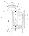
図5は、電力制御装置を搭載する駆動装置100におけるA室71、B室72、C室73、D室74、エンジンコンパートメント室75と、B,C,D室72〜74を伝わる伝熱量H3〜H5と、固定台座22、薄板23、基板ステー14を伝わる伝熱量H1,H2,H6を示している。各伝熱量(H1〜H6)は図5の中で白抜きの矢印で示し、矢印の方向は熱の伝わる方向を示している。なお、図5においては、電力制御装置の各機器の記載は省略している。
FIG. 5 shows a heat transfer amount H3 transmitted through the
図6は図5に示した各室71〜75及び、固定台座22、薄板23、基板ステー14、冷却器27の温度の概要を示す温度グラフ図であり、特に、重負荷運転状態において冷却水の水温T2より潤滑油の油温T0が高い場合における温度分布について記載したものである。図6の横軸はA室71からエンジンコンパートメント室75までの伝熱経路を模式的に示したもので、位置P1からP2の間はA室71を示し、位置P2から位置P3までの間は固定台座22を示し、位置P3から位置P4までの間はB室72を示し、位置P4から位置P5までの間は薄板23を示し、位置P5から位置P6までの間はC室73を示し、位置P6から位置P9までの間は冷却器27を示し、位置P9から位置P10までの間は基板ステー14を示し、位置P10から位置P11までの間は制御基板29を示し、位置P11から位置P12までの間はD室74を示し、位置P12から位置P13までの間はカバー43を示し、位置P13から右は、エンジンコンパートメント室75を示す。また、位置P7から位置P8までの間は冷却器27の冷却水路を示している。従って、位置P7から位置P8までの間の温度は、冷却水の水温T2となっている。FIG. 6 is a temperature graph showing an outline of the temperatures of the
重負荷運転状態では、図6に示すように、図5のトランスアクスル30側のA室71内の潤滑油の油温T0が冷却水の水温T2に比べて高温となる。このため、図5のトランスアクスルケース内のA室71内における潤滑油の飛散によってA室71の温度は潤滑油の油温T0まで上昇し、固定台座22のA室71に側の表面温度も潤滑油の油温T0近くまで上昇する。固定台座22は、例えば、固定台座22はインサート成形によりバスバーを内部に有する熱硬化性樹脂(例えば、フェノール樹脂比熱=1.57〜1.76j/g・K)で形成されているため、アルミニウムの隔壁に比べて比熱が大きく(アルミニウム比熱=0.9j/g・K)、また、熱伝導率が小さく、断熱性が高い。このため、固定台座22を通ってA室71からB室72への熱伝導により流れる熱量H1は小さく、固定台座22のB室72側の温度はA室71側の温度に比べて大きく低下する。In the heavy load operation state, as shown in FIG. 6, the oil temperature T 0 of the lubricating oil in the
薄板23と固定台座22の間のB室72は断熱室となっていることから、B室72を通って伝達される伝熱量H3は小さいので、B室72のトランスアクスル30側の位置P3の温度と冷却器27側の位置P4の温度はあまり大きく変化しない。また、薄板23と冷却器27の冷却器ベース11とで形成されるC室73も同様の断熱室になっているので、C室74を通って伝達される伝熱量H4も小さなものとなっている。従ってC室73のトランスアクスル30側の位置P5の温度は、冷却器27の表面温度と略同等の温度となっている冷却器27側の位置P6の温度より若干高い程度の温度となっている。このように、C室73の内部の温度は、C室73が断熱室となっていることから、冷却器27の表面温度に略近い温度となっている。以上説明した様に樹脂製の固定台座22の断熱性と、B室72、C室73が断熱室となっていることから、トランスアクスル30側のA室71内の潤滑油の油温T0が冷却器27の冷却水の水温T2よりも高い場合であってもトランスアクスル30からの伝熱は固定台座22、B室72、C室73の断熱性によって制限され、冷却器27の温度は大きく上昇しない。また、図5に示すように、A室71の隔壁を伝わった第3の熱量H2はPCU20を覆うカバー43に到達するカバー43の厚みは、トランスアクスルケース31よりも薄いものであることから、その伝熱量は小さく、カバー43の温度がA室71からの熱伝導によって大きく上昇することはない。またカバー43の外面は、トランスアクスル30の潤滑油の温度T0よりも低い温度の温度T1のエンジンコンパーメント室75に接していることから、図6の右側に示すように、その外表面温度は、潤滑油の温度T0よりも温度の低いエンジンコンパートメント室75の温度T1と略と同様の温度となる。Since the
また、D室74もB室72、C室73と同様に断熱室を構成していることから、図6に示すように、D室74の伝熱量は少なく、このため、D室74のカバー43側の位置P12の温度はD室の冷却器27側の位置P11の温度とあまり変わらない温度となる。以上説明したように、カバー43とD室74の断熱性によってカバー43側から冷却器27に伝わる熱量も小さいものとなっている。そして、制御基板29は、冷却器27に基板ステー14を介して接続されているので、熱量H6が制御基板29から冷却27に流れ、これにより、制御基板29は、効果的に冷却器27によって冷却され、その温度は、冷却器27の冷却水温T2に近い温度となる。また、基板ステー14は、平均的な冷却水温度より低い温度となっている冷却水導入部に接続されているので、より効果的の制御基板29を冷却することができる。Further, since the
図7は電力制御装置を車両前方方向に傾斜させた傾斜搭載を示す断面図である。上述した実施形態では、PCU20を水平となるように搭載したが、図7のPCU20は、トランスアクスルケース内のモータジェネレータMG1,MG2及びデフギアの配置により傾斜角θだけ傾けてトランスアクスル30上に配置されている。図7の冷却水は、冷却器27の上側から冷却管17を通り、冷却器27を上から下へ流れて下側の冷却管17から排出される。この流れは、発熱による自然対流とは逆の対向流となっている。
FIG. 7 is a cross-sectional view showing an inclined mounting in which the power control device is inclined in the vehicle front direction. In the above-described embodiment, the
本実施形態では、パワー素子とモータジェネレータとを接続するケーブルにバスバーを用いることにより、パワー素子から放出される熱の一部がPCUケース内に放出される。このため、暖められた空気は、PCUケース上面に沿って上側に流れ、PCU20の上側に集まることになる。そこで、図7の本実施形態では、吸熱前の冷却水をPCU上側から供給し、暖められた空気を冷却器27で冷却することにより、冷やされた空気はPCUケース下面に沿ってPCU下側に流れる事になり、PCU内部の空気を対流させることで内部雰囲気温度を下げることが可能となる。また、トランスアクスル30からの熱の侵入を防ぐ固定台座22により上記対流が妨げられることはない。このように、PCU20を傾斜角θだけ傾けて搭載し、吸熱前の冷却水をPCU上側から供給することにより、積極的にPCUケース内部の空気を対流させることが可能である。
In the present embodiment, by using a bus bar for the cable connecting the power element and the motor generator, a part of the heat released from the power element is released into the PCU case. For this reason, the warmed air flows upward along the upper surface of the PCU case and collects on the upper side of the
以上、上述したように、本発明に係る電力制御装置(PCU)の搭載構造を用いることにより、電力制御装置を構成する昇圧コンバータ及びインバータとモータとを1つのケースに収めて一体化する構造において、固定台座22と薄板23により形成されるB室72及び、冷却器27の両隣で形成されるC室73とD室74が断熱室となっているので対流熱の防止が可能であり、固定台座22は熱伝導率が低い材質とすることによって断熱性を高め、カバー43は薄板の構成にすることにより、トランスアクスルケース31からの熱伝導を抑制することができるので、冷却液導入部に接続された制御基板29を十分冷却することができる。このような機能により、電力制御装置の温度上昇を防止し、制御基板29の冷却性を確保することが可能となる。
As described above, in the structure in which the step-up converter, the inverter, and the motor constituting the power control device are integrated in one case by using the mounting structure of the power control device (PCU) according to the present invention. Since the
10 駆動装置、11 冷却器ベース、12 熱伝導ベース、13 パワー素子、14 基板ステー、17,17a,17b 冷却管、20 PCU、21 端子台、22 固定台座、23 薄板、24 フィルタ用コンデンサ、25 DC/DCコンバータ、26 ボルト、27 冷却器、28 平滑コンデンサ、29 制御基板、30 トランスアクスル、31 トランスアクスルケース、32,33 ステータ、32a,33a ステータコイル端子、34,35 ロータ、36,37 シャフト、38 リアクトル、42 外部コネクタ、43 カバー、44 バスバー、50 冷却装置、51 面シール、52 ゴムリング、55 冷却路、56 ラジエータ、57 ファン、58 ポンプ、61a,61b 放熱シート、62,63,64 配管、71 A室、72 B室、73 C室、74 D室、75 エンジンコンパートメント室、81 トランスアクスル室、82 PCU室、100 駆動装置、102 開口部、107,108 冷却器、109 パワー素子基板、300 リアクトル収容室、320 オイル抜き孔、340 収容室開口部、L1 リアクトル、C2 コンデンサ、MG1,MG2 モータジェネレータ。
DESCRIPTION OF
Claims (4)
電力制御装置は、
モータケースの開口部に取付けられ、樹脂によって形成された固定台座と、
固定台座の上に配置されパワーモジュールを有する冷却器と、
冷却器の上に接続された熱伝導性の基板取付け台と、
基板取付け台の上に接続された制御基板と、
金属製の薄板で形成された電力制御装置全体を覆うカバーと、
固定台座と冷却器との間に設けられる第一の断熱室と、
冷却器とカバーとの間に設けられる第二の断熱室と、
を備え、
モータケースから電力制御装置への熱の伝導を、固定台座と、第一、第二の断熱室と、カバーとによって抑制することにより制御基板の温度上昇を防止する電力制御装置の搭載構造。In the mounting structure of the power control device that mounts the power control device that controls the rotating electrical machine on the motor case that houses the rotating electrical machine that drives the vehicle,
The power control device
A fixed base attached to the opening of the motor case and formed of resin;
A cooler disposed on a fixed base and having a power module;
A thermally conductive substrate mount connected above the cooler;
A control board connected on the board mount;
A cover covering the entire power control device formed of a thin metal plate;
A first heat insulating chamber provided between the fixed base and the cooler;
A second heat insulating chamber provided between the cooler and the cover;
With
A structure for mounting a power control device that prevents a temperature rise of a control board by suppressing heat conduction from the motor case to the power control device by a fixed base, first and second heat insulation chambers, and a cover.
冷却器に取り付けられた基板取付け台は、冷却水の導入側近傍に伝熱可能に接続され、
制御基板は、基板取付け台を介して冷却器に伝熱可能に接続されている電力制御装置の搭載構造。In the mounting structure of the power control device according to claim 1,
The board mounting base attached to the cooler is connected to the vicinity of the cooling water introduction side so that heat can be transferred,
The control board is a mounting structure of a power control device that is connected to the cooler via a board mounting base so that heat can be transferred.
固定台座は、
冷却器と固定台座との熱の伝導を抑制する金属製の薄板と、
冷却器と薄板と固定台座とを共締めにより固定する固定手段と、
を有し、
薄板は、冷却器と薄板とにより囲まれた空間を形成し、薄板は冷却器によって冷却される電力制御装置の搭載構造。In the mounting structure of the power control device according to claim 2,
The fixed base is
A metal thin plate that suppresses heat conduction between the cooler and the fixed base;
Fixing means for fixing the cooler, the thin plate, and the fixed base together by fastening;
Have
The thin plate forms a space surrounded by the cooler and the thin plate, and the thin plate is a mounting structure of the power control device that is cooled by the cooler.
さらに、カバーは、固定台座の周囲を取り囲むように設けられたモータケースのフランジ部に取り付けられることで、モータケースから電力制御装置への熱の伝導をカバーによって抑制する電力制御装置の搭載構造。In the mounting structure of the power control device according to claim 3,
Furthermore, the cover is attached to a flange portion of the motor case provided so as to surround the periphery of the fixed pedestal, and thus the power control device mounting structure that suppresses heat conduction from the motor case to the power control device by the cover.
Priority Applications (1)
| Application Number | Priority Date | Filing Date | Title |
|---|---|---|---|
| JP2012555799A JP5638094B2 (en) | 2011-01-31 | 2012-01-23 | Mounting structure of power control device |
Applications Claiming Priority (4)
| Application Number | Priority Date | Filing Date | Title |
|---|---|---|---|
| JP2011017687 | 2011-01-31 | ||
| JP2011017687 | 2011-01-31 | ||
| JP2012555799A JP5638094B2 (en) | 2011-01-31 | 2012-01-23 | Mounting structure of power control device |
| PCT/JP2012/051335 WO2012105353A1 (en) | 2011-01-31 | 2012-01-23 | Mounting structure for power control unit |
Publications (2)
| Publication Number | Publication Date |
|---|---|
| JPWO2012105353A1 JPWO2012105353A1 (en) | 2014-07-03 |
| JP5638094B2 true JP5638094B2 (en) | 2014-12-10 |
Family
ID=46602572
Family Applications (1)
| Application Number | Title | Priority Date | Filing Date |
|---|---|---|---|
| JP2012555799A Expired - Fee Related JP5638094B2 (en) | 2011-01-31 | 2012-01-23 | Mounting structure of power control device |
Country Status (5)
| Country | Link |
|---|---|
| US (1) | US9210829B2 (en) |
| JP (1) | JP5638094B2 (en) |
| CN (1) | CN103339839B (en) |
| DE (1) | DE112012000617T5 (en) |
| WO (1) | WO2012105353A1 (en) |
Families Citing this family (52)
| Publication number | Priority date | Publication date | Assignee | Title |
|---|---|---|---|---|
| CN103298635A (en) * | 2011-11-14 | 2013-09-11 | 本田技研工业株式会社 | Electric vehicle |
| WO2014057622A1 (en) * | 2012-10-09 | 2014-04-17 | 富士電機株式会社 | Power converter |
| WO2014142245A1 (en) * | 2013-03-14 | 2014-09-18 | 矢崎総業株式会社 | Electronic-component assembly structure and junction box |
| JP6128010B2 (en) * | 2014-02-25 | 2017-05-17 | トヨタ自動車株式会社 | Electric vehicle |
| US10391849B2 (en) * | 2014-04-25 | 2019-08-27 | Aisin Aw Co., Ltd. | Vehicle drive device |
| DE102014106570B4 (en) * | 2014-05-09 | 2016-03-31 | Semikron Elektronik Gmbh & Co. Kg | Power semiconductor module with switching device and arrangement hereby |
| CN105451503B (en) * | 2014-07-21 | 2019-03-08 | 联想(北京)有限公司 | A kind of electronic equipment |
| CN105460079B (en) * | 2014-09-05 | 2018-05-01 | 本田技研工业(中国)投资有限公司 | A kind of automotive windshields device and the automobile equipped with the wind-proof device |
| JP6429889B2 (en) * | 2014-09-25 | 2018-11-28 | 日立オートモティブシステムズ株式会社 | Power converter |
| KR101653453B1 (en) * | 2014-11-03 | 2016-09-09 | 현대모비스 주식회사 | Cooling system for cooling both sides of power semiconductor |
| US10352430B2 (en) * | 2015-03-10 | 2019-07-16 | Ford Global Technologies, Llc | Insulated vehicle wall structures |
| US9454189B1 (en) * | 2015-04-16 | 2016-09-27 | Quanta Computer Inc. | Systems and methods for distributing power in a server system |
| CN104916612A (en) * | 2015-05-06 | 2015-09-16 | 嘉兴斯达微电子有限公司 | Power module and making method thereof |
| JP6787677B2 (en) * | 2016-03-15 | 2020-11-18 | 本田技研工業株式会社 | Electric power unit |
| JP6631355B2 (en) * | 2016-03-25 | 2020-01-15 | 日産自動車株式会社 | Cooling structure of in-wheel motor unit |
| JP6354801B2 (en) * | 2016-07-21 | 2018-07-11 | トヨタ自動車株式会社 | Boost converter |
| FR3063201B1 (en) * | 2017-02-17 | 2020-03-06 | Valeo Equipements Electriques Moteur | INVERTER OF ROTATING ELECTRIC MACHINE WITH IMPROVED COOLING |
| WO2018193588A1 (en) * | 2017-04-20 | 2018-10-25 | 三菱電機株式会社 | Power conversion device |
| JP6491703B2 (en) * | 2017-07-13 | 2019-03-27 | 本田技研工業株式会社 | Vehicle and drive circuit unit |
| CN107512232A (en) * | 2017-07-15 | 2017-12-26 | 北京华田汽车科技有限公司 | A kind of power control unit structure |
| JP6879870B2 (en) * | 2017-09-07 | 2021-06-02 | 日立Astemo株式会社 | Electric drive device and electric power steering device |
| CN109475066B (en) * | 2017-09-08 | 2020-07-03 | 湖南中车时代电动汽车股份有限公司 | Control device for power system of electric automobile |
| EP3681258A4 (en) * | 2017-09-08 | 2021-04-14 | Hunan CRRC Times Electric Vehicle Co., Ltd | Control device for power system of electric vehicle |
| CN107529305A (en) * | 2017-09-25 | 2017-12-29 | 科比传动技术(上海)有限公司 | Circuit board arrangement, drive control device and water pump all-in-one |
| JP7112016B2 (en) * | 2017-12-20 | 2022-08-03 | 三菱自動車工業株式会社 | Inverter-integrated motor mounting structure on vehicle |
| JP6621491B2 (en) * | 2018-03-15 | 2019-12-18 | 三菱電機株式会社 | Rotating electric machine |
| JP7095373B2 (en) * | 2018-04-11 | 2022-07-05 | 三菱自動車工業株式会社 | Inverters and electric vehicles |
| JP6918225B2 (en) * | 2018-05-14 | 2021-08-11 | 三菱電機株式会社 | Power converter |
| KR102536589B1 (en) * | 2018-05-15 | 2023-05-25 | 에이치엘만도 주식회사 | Device for controlling electric drive |
| US10405466B1 (en) | 2018-06-14 | 2019-09-03 | Ford Global Technologies, Llc | Power-module assembly with endcap |
| FR3083421B1 (en) * | 2018-06-28 | 2021-05-21 | Valeo Siemens Eautomotive France Sas | ELECTRICAL EQUIPMENT INCLUDING A DISSIPATION SUPPORT PLATE DEVICE |
| JP7208757B2 (en) * | 2018-10-03 | 2023-01-19 | 川崎重工業株式会社 | Control device |
| CN111196144B (en) * | 2018-11-16 | 2023-04-21 | 丰田自动车株式会社 | Vehicle drive device |
| JP7230451B2 (en) * | 2018-11-19 | 2023-03-01 | トヨタ自動車株式会社 | Layout structure of front space of hybrid vehicle |
| JP7056533B2 (en) * | 2018-11-29 | 2022-04-19 | 株式会社デンソー | Power converter |
| JP2020137392A (en) * | 2019-02-26 | 2020-08-31 | 本田技研工業株式会社 | Power control unit seal structure |
| JP2020141443A (en) * | 2019-02-26 | 2020-09-03 | 本田技研工業株式会社 | Power control unit |
| CN111835209A (en) * | 2019-04-23 | 2020-10-27 | 台达电子工业股份有限公司 | Mounting assembly and inverter assembly suitable for same |
| KR102663609B1 (en) * | 2019-05-03 | 2024-05-07 | 현대자동차주식회사 | Power converting apparatus |
| US11005326B2 (en) * | 2019-07-11 | 2021-05-11 | GM Global Technology Operations LLC | Electric drive unit having cover assembly with integrated cooling channels |
| JP7098063B2 (en) * | 2019-07-17 | 2022-07-08 | 三菱電機株式会社 | Motor device and EGR valve device |
| JP7151686B2 (en) * | 2019-10-15 | 2022-10-12 | トヨタ自動車株式会社 | Power converter controller and fuel cell system |
| JP6854936B1 (en) * | 2020-01-20 | 2021-04-07 | 三菱電機株式会社 | Rotating machine |
| JP7279661B2 (en) * | 2020-02-18 | 2023-05-23 | トヨタ自動車株式会社 | power control unit |
| JP6997245B2 (en) * | 2020-03-31 | 2022-01-17 | 本田技研工業株式会社 | Rotary machine drive unit |
| JP2021166441A (en) * | 2020-04-07 | 2021-10-14 | 株式会社デンソー | Drive device with conversion circuit |
| JP7448032B2 (en) * | 2020-10-28 | 2024-03-12 | 株式会社アイシン | Vehicle drive system |
| JP7420054B2 (en) | 2020-11-09 | 2024-01-23 | トヨタ自動車株式会社 | vehicle transaxle |
| DE102021201248A1 (en) | 2021-02-10 | 2022-08-11 | Vitesco Technologies Germany Gmbh | Control module for a vehicle with at least one electric motor and a transmission |
| DE102021201249A1 (en) | 2021-02-10 | 2022-08-11 | Vitesco Technologies Germany Gmbh | Control module for a vehicle with at least one electric motor and a transmission |
| JP7427345B2 (en) * | 2021-07-01 | 2024-02-05 | ダイハツ工業株式会社 | busbar structure |
| CN114727448B (en) * | 2022-03-18 | 2023-02-07 | 扬州瑞科电子有限公司 | Non-isolated step-down LED controller for LED lighting |
Family Cites Families (9)
| Publication number | Priority date | Publication date | Assignee | Title |
|---|---|---|---|---|
| ATA105093A (en) * | 1993-05-28 | 2001-07-15 | Steyr Daimler Puch Ag | LIQUID-COOLED DRIVE UNIT FOR AN ELECTROMOBILE |
| US5491370A (en) * | 1994-01-28 | 1996-02-13 | General Motors Corporation | Integrated AC machine |
| JP4310683B2 (en) * | 2003-05-13 | 2009-08-12 | アイシン・エィ・ダブリュ株式会社 | Drive unit with built-in electric motor |
| JP4692263B2 (en) | 2005-12-14 | 2011-06-01 | トヨタ自動車株式会社 | Vehicle drive device |
| JP2007220794A (en) * | 2006-02-15 | 2007-08-30 | Toyota Motor Corp | Capacitor device |
| JP4591428B2 (en) | 2006-09-13 | 2010-12-01 | トヨタ自動車株式会社 | Vehicle drive device |
| JP4253684B1 (en) * | 2007-12-05 | 2009-04-15 | トヨタ自動車株式会社 | Vehicle drive device |
| JP5377907B2 (en) | 2008-08-28 | 2013-12-25 | 東芝三菱電機産業システム株式会社 | Drive device using electric motor |
| CN101460045A (en) * | 2008-12-26 | 2009-06-17 | 江苏雅迪科技发展有限公司 | Water-cooling controller for electric vehicle |
-
2012
- 2012-01-23 CN CN201280006696.8A patent/CN103339839B/en active Active
- 2012-01-23 DE DE112012000617T patent/DE112012000617T5/en not_active Withdrawn
- 2012-01-23 WO PCT/JP2012/051335 patent/WO2012105353A1/en active Application Filing
- 2012-01-23 US US13/980,498 patent/US9210829B2/en active Active
- 2012-01-23 JP JP2012555799A patent/JP5638094B2/en not_active Expired - Fee Related
Also Published As
| Publication number | Publication date |
|---|---|
| CN103339839B (en) | 2015-12-09 |
| US20130301220A1 (en) | 2013-11-14 |
| DE112012000617T5 (en) | 2013-11-07 |
| US9210829B2 (en) | 2015-12-08 |
| CN103339839A (en) | 2013-10-02 |
| WO2012105353A1 (en) | 2012-08-09 |
| JPWO2012105353A1 (en) | 2014-07-03 |
Similar Documents
| Publication | Publication Date | Title |
|---|---|---|
| JP5638094B2 (en) | Mounting structure of power control device | |
| JP5261514B2 (en) | Mounting structure of power control device | |
| US7775060B2 (en) | Drive unit for electric vehicle | |
| CN109311376B (en) | Electric axle drive for a vehicle | |
| JP2012041033A (en) | Heating part cooling structure for hybrid electric automobile | |
| US8018103B2 (en) | Driving mechanism | |
| CN102638133B (en) | Permanent magnet motor | |
| JP2016077116A (en) | Vehicle motor apparatus | |
| KR20130141502A (en) | Coolant channels for electric machine stator | |
| US20230118102A1 (en) | An electric turbomachine | |
| CN111869057B (en) | Rotating electric machine with brush | |
| JP2020114087A (en) | In-vehicle cooling device | |
| JP2006197785A (en) | Cooling device of motor | |
| JP5917102B2 (en) | Inverter device, electric drive system | |
| JP4889517B2 (en) | Rotating electrical machine equipment | |
| JP6733405B2 (en) | Electric vehicle cooling structure | |
| CN113555996A (en) | High-efficiency high-power electronic water pump | |
| JP2007181282A (en) | Dynamo-electric machine | |
| JP7460960B2 (en) | Cooling structure for power generating unit of range extender vehicle | |
| JP5404836B2 (en) | Power converter | |
| JP5554395B2 (en) | Electric turbocharger | |
| JP3707477B2 (en) | Vehicle alternator | |
| JP7480274B2 (en) | Inverter integrated motor | |
| CN215772776U (en) | High-efficiency high-power electronic water pump | |
| CN109347238A (en) | motor, air conditioner and vehicle |
Legal Events
| Date | Code | Title | Description |
|---|---|---|---|
| TRDD | Decision of grant or rejection written | ||
| A01 | Written decision to grant a patent or to grant a registration (utility model) |
Free format text: JAPANESE INTERMEDIATE CODE: A01 Effective date: 20140930 |
|
| A61 | First payment of annual fees (during grant procedure) |
Free format text: JAPANESE INTERMEDIATE CODE: A61 Effective date: 20141021 |
|
| R151 | Written notification of patent or utility model registration |
Ref document number: 5638094 Country of ref document: JP Free format text: JAPANESE INTERMEDIATE CODE: R151 |
|
| R250 | Receipt of annual fees |
Free format text: JAPANESE INTERMEDIATE CODE: R250 |
|
| R250 | Receipt of annual fees |
Free format text: JAPANESE INTERMEDIATE CODE: R250 |
|
| R250 | Receipt of annual fees |
Free format text: JAPANESE INTERMEDIATE CODE: R250 |
|
| R250 | Receipt of annual fees |
Free format text: JAPANESE INTERMEDIATE CODE: R250 |
|
| R250 | Receipt of annual fees |
Free format text: JAPANESE INTERMEDIATE CODE: R250 |
|
| R250 | Receipt of annual fees |
Free format text: JAPANESE INTERMEDIATE CODE: R250 |
|
| LAPS | Cancellation because of no payment of annual fees |