JP5014262B2 - Imaging apparatus, control method thereof, and program - Google Patents
Imaging apparatus, control method thereof, and program Download PDFInfo
- Publication number
- JP5014262B2 JP5014262B2 JP2008148319A JP2008148319A JP5014262B2 JP 5014262 B2 JP5014262 B2 JP 5014262B2 JP 2008148319 A JP2008148319 A JP 2008148319A JP 2008148319 A JP2008148319 A JP 2008148319A JP 5014262 B2 JP5014262 B2 JP 5014262B2
- Authority
- JP
- Japan
- Prior art keywords
- lens
- information
- image
- zoom operation
- dust
- Prior art date
- Legal status (The legal status is an assumption and is not a legal conclusion. Google has not performed a legal analysis and makes no representation as to the accuracy of the status listed.)
- Expired - Fee Related
Links
Images


Landscapes
- Studio Devices (AREA)
Description
本発明は、CCDやCMOSセンサ等の撮像素子を用いた撮像装置における、光学ローパスフィルター等の表面に付着した異物による画質劣化を抑制する技術に関する。 The present invention relates to a technique for suppressing image quality deterioration due to foreign matter adhering to the surface of an optical low-pass filter or the like in an imaging apparatus using an imaging element such as a CCD or CMOS sensor.
近年、デジタルカメラやデジタルビデオカメラなどのように、CCD等の撮像素子を用いて画像信号を生成し、それをデータとして記録する撮像装置が数多く出回るようになってきている。デジタルカメラでは、従来記録媒体として使用していた感光フィルムが不要になり、これに代わって半導体メモリカードやハードディスク装置等のデータ記録媒体にデータ化された画像を記録する。これらのデータ記録媒体はフィルムと違って何度でも書き込み、消去が可能であるので、消耗品にかかる経費が少なくて済み、大変便利である。 2. Description of the Related Art In recent years, many image pickup apparatuses that generate image signals using an image pickup device such as a CCD and record the data as data, such as digital cameras and digital video cameras, have come into circulation. In a digital camera, a photosensitive film that has been used as a conventional recording medium is no longer necessary, and instead of this, a data image is recorded on a data recording medium such as a semiconductor memory card or a hard disk device. Since these data recording media can be written and erased any number of times unlike films, the cost for consumables can be reduced, which is very convenient.
通常、デジタルカメラには撮像画像を随時表示可能なLCD(液晶表示器)モニタ装置と、着脱可能な大容量記憶装置が搭載されている。 Usually, a digital camera is equipped with an LCD (Liquid Crystal Display) monitor device capable of displaying captured images at any time and a detachable mass storage device.
これら二つの装置を備えたデジタルカメラを利用すると、従来消耗品として使用してきた記録媒体であるフィルムが不要になるばかりでなく、撮像した画像をLCDモニタ装置に表示してその場で直ちに確認できる。したがって、満足の得られない画像データはその場で消去したり、必要に応じて再撮影したりすることが可能となり、フィルムを用いる銀塩カメラと比較すると、写真撮影の効率が飛躍的に高まったと言える。 Using a digital camera equipped with these two devices not only eliminates the need for a film as a recording medium that has been used as a consumable item in the past, but also allows the captured image to be displayed on the LCD monitor device and immediately confirmed on the spot. . Therefore, unsatisfactory image data can be erased on the spot or re-photographed as needed, and the efficiency of photography is dramatically increased compared to film cameras using film. I can say.
このような利便性と撮像素子の多画素化などの技術革新により、デジタルカメラの利用範囲は拡大してきており、近年では一眼レフ方式などレンズ交換が可能なデジタルカメラも多くなってきている。
しかしながら、デジタルカメラでは、撮像素子に固定された撮像素子保護ガラス、光学フィルター等の表面上や光学系(以下、まとめて撮像素子光学系部品)にゴミ、ほこりなどの異物(以下、単にゴミ)が付着する場合がある。このように撮像素子光学系部品にゴミが付着すると、そのゴミによって光が遮られ、その部分が撮影されないなど、撮影した画像の品質が低下するという問題があった。 However, in a digital camera, foreign matter such as dust or dust (hereinafter simply dust) on the surface of the image sensor protective glass fixed to the image sensor, an optical filter, or the optical system (hereinafter collectively referred to as an image sensor optical system component). May adhere. When dust adheres to the image sensor optical system component in this way, there is a problem that the quality of the photographed image is deteriorated, for example, light is blocked by the dust and the portion is not photographed.
デジタルカメラに限らず銀塩フィルムを用いるカメラにおいても、フィルム上にゴミが存在すると写りこんでしまう問題はあったが、フィルムの場合は1コマごとにフィルムが移動するため、全てのコマに同様のゴミが写りこむことは大変稀である。 Not only digital cameras but also cameras using silver halide film have a problem of being captured if there is dust on the film, but in the case of film, the film moves from frame to frame, so it is the same for all frames It is very rare for trash to appear.
しかし、デジタルカメラの撮像素子は移動せず、共通した撮像素子で撮影を行うため、撮像素子光学系部品に一度ゴミが付着すると、多くのコマ(撮影画像)に同様のゴミが写りこんでしまう。特にレンズ交換式のデジタルカメラにおいては、レンズ交換時にカメラ内にゴミが入り込みやすいという問題がある。 However, since the image sensor of the digital camera does not move and images are taken with a common image sensor, once the dust adheres to the image sensor optical system parts, the same dust appears in many frames (photographed images). . Particularly in an interchangeable lens digital camera, there is a problem that dust easily enters the camera when the lens is replaced.
したがって、撮影者は撮像素子光学系部品へのゴミの付着に常時気を使わねばならず、ゴミのチェックや清掃に多くの労力を費やしていた。特に撮像素子は、カメラ内部の比較的奥まったところに配置されているため、清掃やゴミの確認は容易ではない。 Therefore, the photographer must always pay attention to the adhesion of dust to the image sensor optical system parts, and has spent a lot of labor on checking and cleaning the dust. In particular, since the image sensor is disposed at a relatively deep location inside the camera, it is not easy to clean or check for dust.
さらにレンズ交換式のデジタルカメラでは、レンズ着脱によりゴミの侵入が容易であるばかりでなく、レンズ交換式デジタルカメラの多くは撮像素子の直前にフォーカルプレーンシャッターを配置しており、撮像素子光学系部品上にゴミが付着しやすい。 In addition, with interchangeable lens digital cameras, not only dust can be easily infiltrated by attaching and detaching the lens, but many of the interchangeable lens digital cameras have a focal plane shutter immediately in front of the image sensor. Garbage easily adheres to the top.
このような撮像素子上のゴミは、通常撮像素子の表面にではなく、保護用のガラスや光学フィルター上に付着しているため、撮影レンズの絞り値や瞳位置により結像状態が異なる。即ち、絞りが開放値に近いとぼやけてしまい、小さいゴミが付着していたとしてもほとんど影響が無くなるが、逆に絞り値が大きくなるとはっきり結像し画像に影響を与えててしまう。 Since such dust on the image sensor usually adheres not to the surface of the image sensor but to the protective glass or optical filter, the imaging state differs depending on the aperture value and pupil position of the photographing lens. That is, if the aperture is close to the open value, the image is blurred, and even if small dust is attached, there is almost no effect. However, if the aperture value is increased, the image is clearly formed and the image is affected.
そこで、レンズの絞りを絞った状態で白い壁などを撮影し、撮像素子上のゴミだけが写った画像を予め用意して通常撮影画像と組み合わせて使用することで、ゴミを目立たなくする方法が知られている(特許文献1参照)。しかし、この方法では、ゴミ検出用に撮影した画像と、それに関連付ける本撮影画像群との対応付けを常に意識しなくてはならず、煩わしいという問題があった。 Therefore, there is a method to make dust inconspicuous by taking a picture of a white wall etc. with the lens aperture closed and preparing an image showing only dust on the image sensor in combination with a normal shot image. It is known (see Patent Document 1). However, in this method, there is a problem that it is necessary to always be aware of the association between the image captured for dust detection and the actual captured image group associated therewith, which is troublesome.
さらに近年では、レンズ交換式のデジタルカメラでも、動画を撮影する機能が備えられているものがある。当然ながら、動画でも静止画と同様にゴミが画像に写りこんでしまうことが問題となる。さらに動画撮影の場合、撮影中にズームイン/ズームアウトを行うことができるため、撮影レンズの絞り値や瞳位置が変化し、各フレームに対するゴミの結像状態が異なってしまうという問題がある。 In recent years, some interchangeable lens type digital cameras have a function of taking a moving image. As a matter of course, the problem is that dust also appears in an image as with a still image. Further, in the case of moving image shooting, zoom-in / zoom-out can be performed during shooting, which causes a problem that the aperture value and pupil position of the shooting lens change, and the dust image formation state for each frame varies.
従って、本発明は上述した課題に鑑みてなされたものであり、その目的は、撮像素子に固定された保護ガラス、フィルター等にゴミが付着した場合でも、撮影した動画像への影響を抑制できるようにすることである。 Therefore, the present invention has been made in view of the above-described problems, and the object thereof is to suppress the influence on a captured moving image even when dust adheres to protective glass, a filter, or the like fixed to the image sensor. Is to do so.
上述した課題を解決し、目的を達成するために、本発明に係わる撮像装置は、撮影レンズにより結像された被写体像を光電変換する撮像素子を有する撮像手段と、前記撮像手段より得られる異物検出用画像信号に含まれる異物の像から、少なくとも前記異物の位置及び大きさの情報を含む異物情報を検出する異物検出手段と、前記撮影レンズの絞り値及び瞳位置の情報を含むレンズ情報を取得するレンズ情報取得手段と、動画像撮影が行われるときに、前記撮像手段から連続的に出力される画像信号に基づいて生成される動画像データを記録するとともに、該動画像データに前記異物情報と前記レンズ情報とを付加して記録する記録手段と、前記撮影レンズのズーム操作の開始および終了を検出するズーム操作検出手段と、を備え、前記ズーム操作検出手段が前記撮影レンズのズーム操作の開始を検出するときに、前記記録手段は新規のフラグメントを作成し、前記ズーム操作検出手段が前記撮影レンズのズーム操作の開始を検出してから、前記撮影レンズのズーム操作の終了を検出するまでの間に、前記レンズ情報取得手段は前記レンズ情報を更新して、前記記録手段は、前記更新されたレンズ情報を前記動画像データに付加して前記新規のフラグメントに記録することを特徴とする。 In order to solve the above-described problems and achieve the object, an imaging apparatus according to the present invention includes an imaging unit having an imaging element that photoelectrically converts a subject image formed by a photographic lens , and a foreign object obtained from the imaging unit. from the image of the foreign matter contained in the detection image signal, and the foreign matter detection means for detecting the foreign substance information including information of the position and size of the foreign substance even without low, the lens including the information of the aperture value and the pupil position of the photographing lens Lens information acquisition means for acquiring information, and when moving image shooting is performed, moving image data generated based on image signals continuously output from the imaging means is recorded, and the moving image data is recorded in the moving image data before comprising recording means for recording added Kikoto product information and the lenses information, and a zoom operation detection means for detecting the start and end of the zoom operation of the imaging lens, the zoom When the operation detection unit detects the start of the zoom operation of the photographing lens, the recording unit creates a new fragment, and after the zoom operation detection unit detects the start of the zoom operation of the photographing lens, until detecting the end of the zoom operation of the imaging lens, the said lens information acquisition means and updating the lens information, the recording unit adds the updated lens information on the moving image data and the It is characterized by recording in a new fragment .
また、本発明に係わる撮像装置の制御方法は、撮影レンズにより結像された被写体像を光電変換する撮像素子を有する撮像手段を備える撮像装置を制御する方法であって、前記撮像手段より得られる異物検出用画像信号に含まれる異物の像から、少なくとも前記異物の位置及び大きさの情報を含む異物情報を検出する異物検出ステップと、前記撮影レンズの絞り値及び瞳位置の情報を含むレンズ情報を取得するレンズ情報取得ステップと、動画像撮影が行われるときに、前記撮像手段から連続的に出力される画像信号に基づいて生成される動画像データを記録するとともに、該動画像データに前記異物情報と前記レンズ情報とを付加して記録する記録ステップと、前記撮影レンズのズーム操作の開始および終了を検出するズーム操作検出ステップと、を備え、前記ズーム操作検出ステップで前記撮影レンズのズーム操作の開始が検出されるときに、前記記録ステップで新規のフラグメントを作成し、前記ズーム操作検出ステップで前記撮影レンズのズーム操作の開始が検出されてから、前記撮影レンズのズーム操作の終了が検出されるまでの間に、前記レンズ情報取得ステップで前記レンズ情報が更新され、前記記録ステップで前記更新されたレンズ情報を前記動画像データに付加して前記新規のフラグメントに記録することを特徴とする。 The image pickup apparatus control method according to the present invention is a method for controlling an image pickup apparatus including an image pickup unit having an image pickup element that photoelectrically converts a subject image formed by a photographing lens , and is obtained from the image pickup unit. from foreign matter images included in the foreign substance detection image signal, comprising the foreign substance detection step of detecting the foreign substance information including information of the position and size of the foreign substance even without less, the information of the aperture value and the pupil position of the photographing lens A lens information acquisition step for acquiring lens information, and when moving image shooting is performed, moving image data generated based on image signals continuously output from the imaging unit is recorded, and the moving image data before Kikoto product information and the lenses information recording step of recording added and the start of the zoom operation of the imaging lens and the zoom operation is detected detects the end stearyl Comprising a flop and, when the start of the zoom operation is detected in the photographing lens in the zoom operation detection step, the create new fragments in the recording step, the zoom operation of the photographing lens by the zoom operation detection step The lens information is updated in the lens information acquisition step and the updated lens information is updated in the recording step from when the start of detection is detected until the end of the zoom operation of the photographing lens is detected. It is added to moving image data and recorded in the new fragment .
本発明によれば、撮像素子に固定された保護ガラス、フィルター等にゴミが付着した場合でも、撮影した動画像への影響を抑制することが可能となる。 According to the present invention, even when dust adheres to protective glass, a filter, or the like fixed to the image sensor, it is possible to suppress the influence on the captured moving image.
以下、本発明の好適な実施形態について、図面を参照して詳細に説明する。 DESCRIPTION OF EMBODIMENTS Hereinafter, preferred embodiments of the present invention will be described in detail with reference to the drawings.
(第1の実施形態)
図1は、本発明の第1の実施形態に係るデジタルカメラ120の外観を示す斜視図、図2は図1の垂直断面図である。
(First embodiment)
FIG. 1 is a perspective view showing an appearance of a
図1において、カメラ本体100の上部には、アクセサリシュー110、光学ファインダ104、AE(自動露出)ロックボタン112、AF(オートフォーカス)の測距点選択ボタン113、撮影操作をするためのレリーズボタン114が設けられている。また、電子ダイヤル411、モードダイヤル60、および外部表示装置409も設けられている。電子ダイヤル411は、他の操作ボタンと併用してカメラに数値を入力したり、撮影モードを切り換えたりするための多機能信号入力装置である。また、外部表示装置409は、液晶表示装置から構成され、シャッタースピード、絞り値、撮影モードなどの撮影条件や、他の情報を表示する。
In FIG. 1, an
また、カメラ本体100の背面には、撮影された画像や各種設定画面などを表示するLCDモニタ装置417、LCDモニタ装置417に撮影した画像を表示する再生スイッチ66、単写/連写スイッチ68、十字配置スイッチ116、メニューボタン124、および電源スイッチ72が設けられている。
Also, on the back of the
単写/連写スイッチ68は、後述するシャッタースイッチSW2(64)を押した場合に、1コマの撮影を行って待機状態とする単写モードと、シャッタースイッチSW2(64)を押している間連続して撮影を行い続ける連写モードとを設定することができる。
The single-shot / continuous-
十字配置スイッチ116は、上下左右に配された4つのボタンと、中央に配されたSETボタン117を有し、ユーザがLCDモニタ装置417に表示されるメニュー項目などの選択や実行をカメラに指示するために用いられる。
The
メニューボタン124は、LCDモニタ装置417にカメラの各種設定を行うためのメニュー画面を表示させるためのボタンである。例えば、撮影モードを選択、設定する時は、このメニューボタン124を押した後、十字配置スイッチ116の上下左右のボタンを操作して希望のモードを選択し、希望のモードが選択された状態でSETボタン117を押すことにより設定が完了する。
The
本実施形態のLCDモニタ装置417は透過型であるため、LCDモニタ装置の駆動だけでは画像を視認することはできず、必ずその裏面には図2に示すようにバックライト照明装置416が必要である。このようにLCDモニタ装置417とバックライト照明装置416は図3に示すように画像表示部28を構成している。
Since the
図2に示すように、本実施形態の撮像装置は、主にカメラ本体100と、交換レンズタイプのレンズユニット300により構成されている。図2において、401は撮影光軸である。
As shown in FIG. 2, the imaging apparatus according to the present embodiment mainly includes a
レンズユニット300において、310は複数のレンズから成る撮像レンズ、312は絞り、306は、レンズユニット300をカメラ本体100と機械的に結合するレンズマウントである。レンズユニット300は、カメラ本体100に対してレンズマウント306を介して着脱可能である。
In the
カメラ本体100において、ミラー130は撮影光路中に配置され、レンズユニット300からの被写体光をファインダ光学系に導く位置(図2に示す位置、斜設位置と呼ぶ)と撮影光路外に退避する位置(退避位置と呼ぶ)との間で移動可能である。なお、ミラー130はクイックリターンミラーの構成としても、ハーフミラーの構成としても、どちらでも構わない。
In the
図2において、ピント板204上にはミラー130から光学ファインダ104に導かれる被写体光が結像される。205はファインダの視認性を向上させるためのコンデンサレンズ、132はペンタゴナルダハプリズムであり、ピント板204およびコンデンサレンズ205を通った被写体光をファインダ観察用の接眼レンズ208および光学ファインダ104に導く。
In FIG. 2, the subject light guided from the
209、210はそれぞれシャッターを構成する後幕と先幕で、これら後幕209、先幕210の開放によって後方に配置されている固体撮像素子である撮像素子14が必要時間だけ露光される。撮像素子14は、その前面に光学ローパスフィルタ418が配設されており、撮像素子14に結像する被写体像の空間周波数を調整している。撮影画像に影響を及ぼすゴミ(異物)は、この光学ローパスフィルタ418に付着し、撮像素子14に結像する被写体像に影として現れることにより、撮影画像の品質を劣化させる。
撮像素子14はプリント基板211に保持されている。このプリント基板211の後方には、もう一枚のプリント基板である表示基板215が配置されている。この表示基板215の反対側の面にLCDモニタ装置417およびバックライト照明装置416が配置されている。
The
200は画像データを記録する記録媒体であり、86は電池(携帯用電源)である。この記録媒体200および電池86は、カメラ本体100に対して着脱可能である。
図3は、本発明の第1の実施形態に係るレンズ交換式のデジタルカメラの回路構成を示すブロック図である。 FIG. 3 is a block diagram illustrating a circuit configuration of the interchangeable lens digital camera according to the first embodiment of the present invention.
まず、レンズユニット300の構成について説明する。
First, the configuration of the
レンズマウント306内には、レンズユニット300をカメラ本体100と電気的に接続する各種機能が含まれている。320は、レンズマウント306において、レンズユニット300をカメラ本体100と接続するためのインターフェース、322はレンズユニット300をカメラ本体100と電気的に接続するコネクタである。
The
コネクタ322は、カメラ本体100とレンズユニット300との間で制御信号、状態信号、データ信号などを伝え合うと共に、各種電圧の電流を供給される機能も備えている。また、コネクタ322は電気通信のみならず、光通信、音声通信などを伝達する構成としても良い。
The
340は測光制御部46からの測光情報に基づいて、後述するカメラ本体100のシャッター12を制御するシャッター制御部40と連携しながら、絞り312を制御する絞り制御部である。342は撮像レンズ310のフォーカシングを制御するフォーカス制御部、344は撮像レンズ310のズーミングを制御するズーム制御部である。
350はレンズユニット300全体を制御するレンズシステム制御回路である。レンズシステム制御回路350は、動作用の定数、変数、プログラムなどを記憶するメモリを備えている。更に、レンズユニット300固有の番号などの識別情報、管理情報、開放絞り値や最小絞り値、焦点距離などの機能情報、現在や過去の各設定値などを保持する不揮発性メモリも備えている。
A lens
次に、カメラ本体100の構成について説明する。
Next, the configuration of the
106はカメラ本体100とレンズユニット300を機械的に結合するレンズマウントである。12は、後幕209および先幕210を備えるシャッターである。撮像レンズ310に入射した光線は、一眼レフ方式によって光量制限手段である絞り312、レンズマウント306及び106、ミラー130、シャッター12を介して導かれ、光学像として被写体像を光電変換する撮像素子14上に結像する。
A
16は、撮像素子14から出力されるアナログ信号をデジタル信号に変換するA/D変換器である。18は撮像素子14、A/D変換器16、D/A変換器26にそれぞれクロック信号や制御信号を供給するタイミング発生回路であり、メモリ制御回路22及びシステム制御回路50により制御される。
20は画像処理回路であり、A/D変換器16からのデータ或いはメモリ制御回路22からのデータに対して所定の画素補間処理や色変換処理を行う。また、画像処理回路20は、必要に応じて、A/D変換器16から出力される画像データを用いて所定の演算処理を行う。得られた演算結果に基づいてシステム制御回路50がシャッター制御部40、焦点調節部42を制御するための、TTL(スルー・ザ・レンズ)方式のオートフォーカス(AF)処理、自動露出(AE)処理、フラッシュプリ発光(EF)処理を行うことができる。さらに、画像処理回路20は、A/D変換器16から出力される画像データを用いて所定の演算処理を行い、得られた演算結果に基づいてTTL方式のオートホワイトバランス(AWB)処理も行っている。
An
なお、本実施形態における図3に示す例では、焦点調節部42及び測光制御部46を専用に備えている。従って、焦点調節部42及び測光制御部46を用いてAF処理、AE処理、EF処理の各処理を行い、画像処理回路20を用いたAF処理、AE処理、EF処理の各処理を行わない構成としても構わない。また、焦点調節部42及び測光制御部46を用いてAF処理、AE処理、EF処理の各処理を行い、さらに、画像処理回路20を用いたAF処理、AE処理、EF処理の各処理を行う構成としてもよい。
In the example shown in FIG. 3 in the present embodiment, the
22はメモリ制御回路であり、A/D変換器16、タイミング発生回路18、画像処理回路20、画像表示メモリ24、D/A変換器26、メモリ30、圧縮・伸長回路32を制御する。A/D変換器16から出力される画像データは、画像処理回路20、メモリ制御回路22を介して、或いはメモリ制御回路22のみを介して、画像表示メモリ24或いはメモリ30に書き込まれる。
A
24は画像表示メモリ、26はD/A変換器、28はLCDモニタ装置417、バックライト照明装置416等から成る画像表示部であり、画像表示メモリ24に書き込まれた表示用の画像データはD/A変換器26を介して画像表示部28により表示される。画像表示部28を用いて、撮像した画像データを逐次表示することで、電子ビューファインダ(EVF)機能を実現することができる。また、画像表示部28は、システム制御回路50の指示により任意に表示をON/OFFすることが可能であり、表示をOFFにした場合にはカメラ本体100の電力消費を大幅に低減することができる。
30は撮影した静止画像を格納するためのメモリであり、所定枚数の静止画像を格納するのに十分な記憶容量を備えている。これにより、複数枚の静止画像を連続して撮影する連写撮影やパノラマ撮影の場合にも、高速かつ大量の画像書き込みをメモリ30に対して行うことが可能となる。また、動画撮影時には、所定レートで連続的に書き込まれる画像のフレームバッファとして使用される。さらに、メモリ30はシステム制御回路50の作業領域としても使用することが可能である。
32は公知の圧縮方法を用いて画像データを圧縮・伸長する圧縮・伸長回路である。圧縮・伸長回路32は、メモリ30に格納された画像を読み込んで圧縮処理或いは伸長処理を行い、処理を終えたデータを再びメモリ30に書き込む。
A compression /
40はシャッター制御部であり、測光制御部46からの測光情報に基づいて絞り312を制御する絞り制御部340と連携しながらシャッター12を制御する。42はAF(オートフォーカス)処理を行うための焦点調節部である。レンズユニット300内の撮像レンズ310に入射した光線を絞り312、レンズマウント306、106、ミラー130及び焦点調節用サブミラー(不図示)を介して一眼レフ方式で入射することにより、光学像として結像された画像の合焦状態を測定する。
46はAE(自動露出)処理を行うための測光制御部である。レンズユニット300内の撮像レンズ310に入射した光線を、絞り312、レンズマウント306、106、ミラー130及び測光用サブミラー(図示せず)を介して一眼レフ方式で入射することにより、光学像として結像された画像の露出状態を測定する。48はフラッシュであり、AF補助光の投光機能、フラッシュ調光機能も有する。測光制御部46はフラッシュ48と連携することにより、EF(フラッシュ調光)処理機能も有する。
A
また、焦点調節部42による測定結果と、A/D変換器16からの画像データを画像処理回路20によって演算した演算結果とを用いて、AF制御を行うようにしてもよい。さらに、測光制御部46による測定結果と、A/D変換器16からの画像データを画像処理回路20によって演算した演算結果とを用いて露出制御を行うようにしてもよい。
Further, the AF control may be performed using the measurement result by the
50はカメラ本体100全体を制御するシステム制御回路であり、周知のCPUなどを内蔵する。52はシステム制御回路50の動作用の定数、変数、プログラム等を記憶するメモリである。
54はシステム制御回路50でのプログラムの実行に応じて、文字、画像、音声などを用いて動作状態やメッセージなどを外部に通知するための通知部である。通知部54としては、例えばLCDやLEDなどによる視覚的な表示を行う表示部や音声による通知を行う発音素子などが用いられるが、これらのうち1つ以上の組み合わせにより構成される。特に、表示部の場合には、例えば外部表示装置409のようにカメラ本体100の操作部70近辺で、視認しやすい、単数あるいは複数箇所に設置されている。また、通知部54は、その一部の機能が光学ファインダ104内に設置されている。
通知部54の表示内容の内、LCDなどの画像表示部28に表示するものとしては以下のものがある。まず、単写/連写撮影表示、セルフタイマ表示等、撮影モードに関する表示がある。また、圧縮率表示、記録画素数表示、記録枚数表示、残撮影可能枚数表示等の記録に関する表示がある。また、シャッター速度表示、絞り値表示、露出補正表示、調光補正表示、外部フラッシュ発光量表示、赤目緩和表示等の撮影条件に関する表示がある。その他に、マクロ撮影表示、ブザー設定表示、電池残量表示、エラー表示、複数桁の数字による情報表示、記録媒体200及びPC210の着脱状態表示がある。更に、レンズユニット300の着脱状態表示、通信I/F動作表示、日付・時刻表示、外部コンピュータとの接続状態を示す表示等も行われる。
Among the display contents of the
また、通知部54の表示内容のうち、光学ファインダ104内に表示するものとしては、例えば、以下のものがある。合焦表示、撮影準備完了表示、手振れ警告表示、フラッシュ充電表示、フラッシュ充電完了表示、シャッター速度表示、絞り値表示、露出補正表示、記録媒体書き込み動作表示等である。
In addition, among the display contents of the
56は後述するプログラムなどが格納された電気的に消去・記録可能な不揮発性メモリであり、例えばEEPROM等が用いられる。
60、62、64、66、68、及び70は、システム制御回路50の各種の動作指示を入力するための操作手段であり、スイッチやダイヤル、タッチパネル、視線検知によるポインティング、音声認識装置等の単数或いは複数の組み合わせで構成される。
ここで、これらの操作手段の具体的な説明を行う。 Here, a specific description of these operating means will be given.
60はモードダイヤルで、自動撮影モード、プログラム撮影モード、シャッター速度優先撮影モード、絞り優先撮影モード、マニュアル撮影モード、焦点深度優先(デプス)撮影モード等の各機能撮影モードを切り替え設定することができる。他に、ポートレート撮影モード、風景撮影モード、接写撮影モード、スポーツ撮影モード、夜景撮影モード、パノラマ撮影モード、動画撮影モードなどの各機能撮影モードを切り替え設定することもできる。
62はシャッタースイッチSW1で、レリーズボタン114の操作途中(例えば半押し)でONとなり、AF処理、AE処理、AWB処理、EF処理等の動作開始を指示する。
64はシャッタースイッチSW2で、レリーズボタン114の操作完了(例えば全押し)でONとなり、露光処理、現像処理、及び記録処理からなる一連の処理の動作開始を指示する。まず、露光処理では、撮像素子14から読み出した信号をA/D変換器16、メモリ制御回路22を介してメモリ30に書き込み、更に、画像処理回路20やメモリ制御回路22での演算を用いた現像処理が行われる。更に、記録処理では、メモリ30から画像データを読み出し、圧縮・伸張回路32で圧縮を行い、記録媒体200あるいはPC210に書き込む、または送信する。
66は再生スイッチであり、撮影モード状態で撮影した画像をメモリ30あるいは記録媒体200、PC210から読み出して画像表示部28に表示する再生動作の開始を指示する。他に、再生モード、マルチ画面再生・消去モード、PC接続モード等の各機能モードを設定することができる。
68は単写/連写スイッチで、シャッタースイッチSW2(64)を押した場合に、1コマの撮影を行って待機状態とする単写モードと、シャッタースイッチSW2(64)を押している間、連続して撮影を行い続ける連写モードとを設定することができる。 68 is a single-shot / continuous-shot switch. When the shutter switch SW2 (64) is pressed, a single-shot mode in which one frame is shot and the camera is in a standby state, and while the shutter switch SW2 (64) is being pressed, continuous shooting is performed. The continuous shooting mode can be set.
70は各種ボタンやタッチパネルなどから成る操作部である。一例として、ライブビュー開始/停止ボタン、動画記録開始/停止ボタン、メニューボタン124、SETボタン117、マルチ画面再生改ページボタン、フラッシュ設定ボタン、単写/連写/セルフタイマー切り換えボタン、十字配置スイッチ116、AE(自動露出)ロックボタン112、AFの測距点選択ボタン113、電子ダイヤル411を含む。更に、再生画像移動+(プラス)ボタン、再生画像移動−(マイナス)ボタン、撮影画質選択ボタン、露出補正ボタン、調光補正ボタン、外部フラッシュ発光量設定ボタン、日付/時間設定ボタンなども含む。なお、上記十字配置スイッチ116の上下左右のボタンの各機能は、回転ダイヤルスイッチを備えることによって、より軽快に数値や機能を選択することが可能となる。
An
また、画像表示部28のON/OFFを設定する画像表示ON/OFFスイッチ、撮影直後に撮影した画像データを自動再生するクイックレビュー機能を設定するクイックレビューON/OFFスイッチがある。また、JPEG圧縮の圧縮率を選択するため、あるいは撮像素子の信号をそのままデジタル化して記録媒体に記録するRAWモードを選択するためのスイッチである圧縮モードスイッチがある。また、ワンショットAFモードとサーボAFモードとを設定可能なAFモード設定スイッチなどがある。ワンショットAFモードでは、シャッタースイッチSW1(62)を押した際にオートフォーカス動作を開始し、一旦合焦した場合、その合焦状態を保ち続ける。サーボAFモードでは、シャッタースイッチSW1(62)を押している間、連続してオートフォーカス動作を続ける。更に、後述するようにゴミ検出用画像を撮影してゴミ情報を取得する、ゴミ情報取得モードを設定することができる設定スイッチを含む。
In addition, there is an image display ON / OFF switch for setting ON / OFF of the
72は電源スイッチであり、カメラ本体100の電源オン、電源オフの各モードを切り替え設定することができる。また、カメラ本体100に接続されたレンズユニット300、外部フラッシュ112、記録媒体200、PC210等の各種付属装置の電源オン、電源オフの設定も合わせて切り替え設定可能である。
80は電源制御部で、電池検出回路、DC−DCコンバータ、通電するブロックを切り替えるスイッチ回路等により構成されている。電源制御部80は、電池の装着の有無、電池の種類、電池残量の検出を行い、検出結果及びシステム制御回路50の指示に基づいてDC−DCコンバータを制御し、必要な電圧を必要な期間、記録媒体を含む各部へ供給する。
A
82、84はコネクタ、86はアルカリ電池やリチウム電池等の一次電池、NiCd電池やNiMH電池、Li‐ion電池、Liポリマー電池等の二次電池、ACアダプター等からなる電源部である。
90及び94はメモリカードやハードディスク等の記録媒体やPCとのインタフェース、92及び96はメモリカードやハードディスク等の記録媒体やPCと接続を行うコネクタである。98はコネクタ92及び/或いは96に記録媒体200或いはPC210が装着されているか否かを検知する記録媒体着脱検知回路である。
Reference numerals 90 and 94 denote recording media such as a memory card and a hard disk, and an interface with a PC.
なお、本実施形態では記録媒体を取り付けるインタフェース及びコネクタを2系統持つものとして説明しているが、記録媒体を取り付けるインタフェース及びコネクタは、単数或いは複数、いずれの系統数を備える構成としても構わない。また、異なる規格のインタフェース及びコネクタを組み合わせて備える構成としても構わない。 Although the present embodiment has been described as having two systems of interfaces and connectors for attaching the recording medium, the interface and connectors for attaching the recording medium may have a single or a plurality of systems. Moreover, it is good also as a structure provided with combining the interface and connector of a different standard.
インタフェース及びコネクタとしては、種々の記憶媒体の規格に準拠したものを用いて構成することが可能である。例えば、PCMCIA(Personal Computer Memory Card International Association)カードやCF(コンパクトフラッシュ(登録商標))カード、SDカード等である。インタフェース90及び94、そしてコネクタ92及び96をPCMCIAカードやCFカード等の規格に準拠したものを用いて構成した場合、各種通信カードを接続することができる。通信カードとしては、LANカードやモデムカード、USB(Universal Serial Bus)カード、IEEE(Institute of Electrical and Electronic Engineers)1394カードがある。他にも、P1284カード、SCSI(Small Computer System Interface)カード、PHS等がある。これら各種通信カードを接続することにより、他のコンピュータやプリンタ等の周辺機器との間で画像データや画像データに付属した管理情報を転送し合うことができる。
As the interface and the connector, it is possible to configure using interfaces that comply with various storage medium standards. For example, a PCMCIA (Personal Computer Memory Card International Association) card, a CF (Compact Flash (registered trademark)) card, an SD card, or the like. When the interfaces 90 and 94 and the
光学ファインダ104には、撮像レンズ310に入射した光線を、一眼レフ方式によって、絞り312、レンズマウント306、106、ミラー130、132を介して導き、光学像として結像させて表示することができる。これにより、画像表示部28による電子ファインダ機能を使用すること無しに、光学ファインダのみを用いて撮影を行うことが可能である。また、光学ファインダ104内には、通知部54の一部の機能、例えば、合焦状態、手振れ警告、フラッシュ充電、シャッター速度、絞り値、露出補正などが表示される。
The
112は、アクセサリシュー110を介して装着される、外部フラッシュ装置である。
120はレンズマウント106内でカメラ本体100をレンズユニット300と接続するためのインターフェースである。
122はカメラ本体100をレンズユニット300と電気的に接続するコネクタである。また、レンズマウント106及びコネクタ122にレンズユニット300が装着されているか否かは、不図示のレンズ着脱検知部により検知される。コネクタ122はカメラ本体100とレンズユニット300との間で制御信号、状態信号、データ信号などを伝え合うと共に、各種電圧の電流を供給する機能も備えている。
A
コネクタ122を介して通信される、レンズユニット300の各種光学情報(絞り、ズーム位置、瞳位置、焦点距離など)は、カメラ本体100のメモリ30に記憶される。通信の要求はカメラ本体100側から行う場合もあれば、レンズユニット300側から情報更新のたびに通信される場合もある。
Various optical information (aperture, zoom position, pupil position, focal length, etc.) of the
また、コネクタ122は電気通信だけでなく、光通信、音声通信などを伝達する構成としてもよい。
Further, the
200はメモリカードやハードディスク等の記録媒体である。この記録媒体200は、半導体メモリや磁気ディスク等から構成される記録部202、カメラ本体100とのインタフェース204、カメラ本体100と接続を行うコネクタ206を備えている。
記録媒体200としては、PCMCIAカードやコンパクトフラッシュ(登録商標)等のメモリカード、ハードディスク等を用いることができる。また、マイクロDAT、光磁気ディスク、CD−RやCD−RW等の光ディスク、DVD等の相変化型光ディスク等で構成されていても勿論構わない。
As the
210はPCであり、磁気ディスク(HD)等から構成される記録部212、カメラ本体100とのインタフェース214、カメラ本体100と接続を行うコネクタ216を備えている。インターフェース94はUSBやIEEE1394などが挙げられるが、特に限定はない。
(ゴミ検出処理)
本実施形態では、まず、撮像素子14の前方に配置された光学ローパスフィルタ418に付着したゴミ(異物)の情報(撮像画面内のゴミの情報)であるゴミ情報(異物情報)を得るためのゴミ検出用画像(異物検出用画像信号)を撮影する。そして、ゴミデータを抽出し、ゴミ補正データ(ゴミ情報プロファイル)を生成しておく。ここでゴミ検出用画像は、できるだけ均一な輝度面を撮影した画像が望ましいが、身近な場所で容易に撮影できることが望ましいため、厳密な均一性を要求するものではない。例えば、青空や白い壁面を撮影することを想定している。
(Dust detection process)
In the present embodiment, first, dust information (foreign matter information) that is information on dust (foreign matter) attached to the optical low-
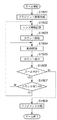
まず、光学ローパスフィルタ418に付着したゴミの位置を検出する処理の例を、図4のフローチャートを用いて説明する。この処理は、システム制御回路50が不揮発性メモリ56に記憶されたゴミ検出処理プログラムを実行することにより実施される。
First, an example of processing for detecting the position of dust attached to the optical low-
ゴミ検出処理は、ゴミ検出用画像を撮像することにより行われる。ゴミ検出処理を行う場合、面光源装置の射出面や白い壁などの均一な色を持つ面にレンズユニット300の撮影光軸401を向けてカメラを設置し、ゴミ検出の準備を行なう。または、レンズマウント106にゴミ検出用のライトユニット(レンズの代わりに装着する小型の点光源装置)を装着し、ゴミ検出の準備を行う。ライトユニットの光源は例えば白色LEDが考えられ、発光面のサイズを予め定めた絞り値(例えば、F32)相当になるように調整するのが望ましい。
The dust detection process is performed by capturing a dust detection image. When performing dust detection processing, a camera is installed with the photographing
本実施形態では、通常の撮影レンズを用いた場合について説明するが、上記のライトユニットをレンズマウント106に取り付けてゴミ検出を行っても良い。このように、本実施形態においてゴミ検出用画像は、均一な色を有する画像である。
In this embodiment, a case where a normal photographing lens is used will be described. However, dust detection may be performed by attaching the light unit to the
準備が終了した後、十字配置スイッチ116からゴミ検出処理の開始が指示されると、システム制御回路50は、まず絞りの設定を行う。撮像素子近傍のゴミはレンズの絞り値によって結像状態が変わり、レンズの瞳位置によって位置が変化する。したがって、ゴミ補正データにはゴミの位置や大きさに加え、検出時の絞り値とレンズの瞳位置を保持する必要がある。
After the preparation is completed, when the start of dust detection processing is instructed from the
ただし、ゴミ補正データを作成する段階で、異なるレンズを用いたとしても常に同じ絞り値を使うことを予め決めておけば、必ずしもゴミ補正データ内に絞り値を保持する必要はない。また、瞳位置に関してもライトユニットを用いたり、特定のレンズのみの使用を許可することで、同様に必ずしもゴミ補正データ内に瞳位置を保持する必要はなくなる。 However, it is not always necessary to hold the aperture value in the dust correction data if it is determined in advance that the same aperture value is always used even when different lenses are used at the stage of creating dust correction data. Similarly, by using a light unit or permitting the use of only a specific lens for the pupil position, it is not always necessary to hold the pupil position in the dust correction data.
つまり、ゴミ補正データを作成する段階において、使用するレンズを複数許したり、絞り込む絞り値を適宜変更する場合には、検出時の絞り値とレンズの瞳位置を、ゴミ補正データ内に保持する必要があると言える。なお、ここで瞳位置とは、射出瞳の撮像面(焦点面)からの距離をいう。 In other words, at the stage of creating dust correction data, if you want to allow multiple lenses to use or change the aperture value to narrow down appropriately, it is necessary to keep the aperture value and lens pupil position at the time of detection in the dust correction data It can be said that there is. Here, the pupil position refers to the distance from the imaging plane (focal plane) of the exit pupil.
ここでは、例えばF22を指定する(ステップS21)。 Here, for example, F22 is designated (step S21).
次にシステム制御回路50はコネクタ122を介して絞り制御部340に対し、レンズユニット300の絞り羽根制御を行わせ、ステップS21で指定された絞り値に絞りを設定する(ステップS22)。さらに、フォーカス制御部342に指示して、フォーカス位置を無限遠に設定する(ステップS23)。
Next, the
撮影レンズの絞り値とフォーカス位置が設定されると、ゴミ検出モードでの撮影を実行する(ステップS24)。ステップS24で行う撮像処理ルーチンの詳細に関しては図9を用いて後に説明する。撮影された画像データは、メモリ30に格納される。
When the aperture value and focus position of the photographing lens are set, photographing in the dust detection mode is executed (step S24). Details of the imaging processing routine performed in step S24 will be described later with reference to FIG. The captured image data is stored in the
撮影が終了すると、撮影時の絞り値とレンズ瞳位置を取得(レンズ情報取得)する(ステップS25)。画像処理回路20にメモリ30に記憶されている撮影画像の各画素に対応するデータを呼び出す(ステップS26)。画像処理回路20は、図6に示す処理を行い、ゴミが存在する画素の位置と大きさを取得する(ステップS27)。ステップS27で取得したゴミが存在する画素の位置と大きさ、およびステップS25で取得した絞り値とレンズ瞳位置情報を、不揮発性メモリ56に登録する(ステップS28)。ここで、前述したライトユニットを用いた場合には、レンズ情報を取得できない。そこで、レンズ情報が取得できない場合は、ライトユニットを使ったと判断し、予め定められたレンズ瞳位置情報と、ライトユニットの光源径から算出される換算絞り値を登録する。
When shooting is completed, the aperture value and lens pupil position at the time of shooting are acquired (lens information acquisition) (step S25). Data corresponding to each pixel of the captured image stored in the
ここで、ステップS28において、予め不揮発性メモリ56に記録されている製造時からの不良画素(画素欠陥)の位置と、読み出した画素データの位置を比べて画素欠陥であるかどうかを確認する。そして、画素欠陥によるものでは無いと判断された領域のみ、不揮発性メモリ56に位置を登録しても良い。
Here, in step S28, the position of the defective pixel (pixel defect) from the time of manufacture recorded in advance in the
不揮発性メモリ56に格納されるゴミ補正データのデータ形式例を図5に示す。図5に示した通り、ゴミ補正データには、検出用画像撮影時の、レンズ情報とゴミの位置、大きさの情報が格納される。
An example of the data format of dust correction data stored in the
具体的には、検出用画像撮影時のレンズ情報として、検出用画像撮影時における実際の絞り値(F値)と、そのときのレンズ瞳位置を格納する。続いて記憶領域に検出したゴミ領域の数(整数値)を格納し、これに続き、個々の具体的なゴミ領域のパラメータを、ゴミ領域の数だけ繰返して格納する。ゴミ領域のパラメータは、ゴミの半径(例えば2バイト)、有効画像領域における中心のx座標(例えば2バイト)、おなじく中心のy座標(例えば2バイト)の3つの数値のセットである。 Specifically, the actual aperture value (F value) at the time of detection image capture and the lens pupil position at that time are stored as lens information at the time of detection image capture. Subsequently, the number of detected dust areas (integer value) is stored in the storage area, and subsequently, individual specific dust area parameters are repeatedly stored by the number of dust areas. The parameter of the dust area is a set of three numerical values: a dust radius (for example, 2 bytes), a center x coordinate (for example, 2 bytes) in the effective image area, and a similar y coordinate (for example, 2 bytes).
不揮発性メモリ56の大きさ等によりゴミ補正データサイズに制限がある場合、ステップS27で得たゴミ領域の先頭から優先してデータを格納する。これは、ステップS27のゴミ領域取得ルーチン内では、後述するようにゴミ領域を、目立つゴミの順にソートするからである。
When the dust correction data size is limited due to the size of the
(ゴミ領域取得ルーチン)
次に、図6から図8を用いて、ステップS27で行うゴミ領域取得ルーチンの詳細について説明する。
(Trash area acquisition routine)
Next, details of the dust region acquisition routine performed in step S27 will be described with reference to FIGS.
図7に示すように、呼び出した画像データをメモリ30上に展開し、予め定められたブロック単位で処理を行う。これは、レンズやセンサ特性に起因する周辺減光に対応するためである。周辺減光とは、レンズの中央部に比べ周辺部の輝度が落ちてしまう現象であり、レンズの絞りを小さくすることである程度軽減されることが知られている。しかし、絞りを絞った状態でも、撮影画像に対して予め定められたスレッショルド値でゴミ位置の判定を行うと、レンズによっては周辺部のゴミが正確に検出できなくなるという問題がある。そこで、画像をブロック分割して周辺減光の影響を軽減する。
As shown in FIG. 7, the called image data is expanded on the
単純にブロック分割すると、ブロックとブロックの間でスレッショルド値が異なる場合、ブロック間をまたぐゴミの検出結果がずれてしまうという問題がある。そこで、ブロック間をオーバーラップさせ、オーバーラップ領域を構成するブロックのいずれかでゴミと判定された画素をゴミ領域として扱う。 When the blocks are simply divided, there is a problem that the detection result of the dust straddling the blocks is shifted when the threshold values are different between the blocks. Therefore, the blocks are overlapped, and pixels determined to be dust in any of the blocks constituting the overlap region are treated as dust regions.
ブロック内のゴミ領域判定は、図6に示す処理の流れで行う。まず、ブロック内の最大輝度Lmax、平均輝度Laveを算出し、次式を用いてブロック内のスレッショルド値T1を算出する。 The determination of the dust area in the block is performed according to the processing flow shown in FIG. First, the maximum luminance Lmax and average luminance Lave in the block are calculated, and the threshold value T1 in the block is calculated using the following equation.
T1=Lave×0.6+Lmax×0.4
次に、スレッショルド値を超えない画素をゴミ画素とし(ステップS61)、ゴミ画素によって構成される孤立領域を各々一つのゴミ領域di(i=0,1,…,n)とする(ステップS62)。図8に示すように、ゴミ領域毎に、ゴミ領域を構成する画素の水平方向の座標の最大値Xmaxおよび最小値Xmin、垂直方向の座標の最大値Ymaxおよび最小値Yminを求め、ゴミ領域diのサイズを表す半径riを次式によって算出する(ステップS63)。
T1 = Lave × 0.6 + Lmax × 0.4
Next, pixels that do not exceed the threshold value are defined as dust pixels (step S61), and isolated regions constituted by dust pixels are each defined as one dust region di (i = 0, 1,..., N) (step S62). . As shown in FIG. 8, for each dust region, the maximum value Xmax and the minimum value Xmin of the horizontal coordinate of the pixels constituting the dust region, the maximum value Ymax and the minimum value Ymin of the vertical coordinate are obtained, and the dust region di is obtained. A radius ri representing the size of is calculated by the following equation (step S63).
ri=√[{(Xmax−Xmin)/2}2+{(Ymax−Ymin)/2}2]
Xmax、Xmin、Ymax、Yminとriの関係を、図8に示す。
ri = √ [{(Xmax−Xmin) / 2} 2 + {(Ymax−Ymin) / 2} 2 ]
FIG. 8 shows the relationship between Xmax, Xmin, Ymax, Ymin and ri.
その後ステップS64で、ゴミ領域毎の平均輝度値を算出する。 Thereafter, in step S64, an average luminance value for each dust region is calculated.
不揮発性メモリ56のサイズによる制限などにより、ゴミ補正データのデータサイズが制限されている場合がある。このような場合に対応するために、ゴミ位置情報を、大きさやゴミ領域の平均輝度値によってソートする(ステップS65)。本実施形態では、riの大きい順にソートする。riが等しい場合、平均輝度値の低い順にソートする。このようにすることで、目立つゴミを優先してゴミ補正データに登録することが出来る。なお、ソート済みのゴミ領域をDi、ゴミ領域Diの半径をRiとする。
The data size of the dust correction data may be limited due to the limitation due to the size of the
なお、予め定められたサイズより大きいゴミ領域がある場合、ソートの対象から外し、ソート済みゴミ領域リストの末尾に配置しても良い。大きいゴミ領域については、後に補間処理をするとかえって画質を低下させる場合があり、補正対象の優先順位としては最下位として扱うことが望ましいからである。 If there is a dust area larger than a predetermined size, it may be excluded from sorting and placed at the end of the sorted dust area list. This is because a large dust region may lower the image quality if interpolation processing is performed later, and is preferably treated as the lowest priority for correction.
(撮像処理ルーチン)
次に、図9に示すフローチャートを用いて、図4のステップS24で行われる撮像処理ルーチンの詳細について説明する。この処理はシステム制御回路50が不揮発性メモリ56に記憶された撮像処理プログラムを実行することにより実施される。
(Imaging processing routine)
Next, the details of the imaging processing routine performed in step S24 of FIG. 4 will be described using the flowchart shown in FIG. This process is performed by the
この撮像処理ルーチンが実行されると、ステップS201でシステム制御回路50は、図2及び図3に示すミラー130を作動させ、いわゆるミラーアップを行い、撮影光路外にミラー130を退避させる。
When this imaging processing routine is executed, in step S201, the
次に、ステップS202で撮像素子14での電荷蓄積を開始し、次のステップS203では図3に示したシャッター12をそれぞれ走行させて露光を行う。そして、ステップS204で撮像素子14の電荷蓄積を終了し、次のステップS205で撮像素子14から画像信号を読み出してA/D変換器16および画像処理回路20で処理した画像データをメモリ30に一次記憶する。
Next, in step S202, charge accumulation in the
次のステップS206で撮像素子14から全ての画像信号の読み出しが終了すると、ステップS207でミラー130をミラーダウンし、ミラーを斜設位置に戻して一連の撮像動作を終了する。
When the reading of all image signals from the
ステップS208にて、通常撮影かゴミ検出用画像撮影かを判断し、通常撮影時にはステップS209へ進んで、撮影した画像が記録媒体200に記録される。
In step S208, it is determined whether normal shooting or dust detection image shooting is performed. When normal shooting is performed, the process proceeds to step S209, and the shot image is recorded on the
(ゴミ除去処理)
次に、上述のゴミ補正データを用いて、静止画像ファイルに対して画像処理によりゴミ除去を行う動作の流れについて、図10を用いて説明する。本実施形態は、動画像ファイルに対してゴミ除去処理を行うものであるが、動画像ファイルに対しても静止画像ファイルに対するゴミ除去処理と同様の手法を適用することができるので、静止画像ファイルに対するゴミ除去処理について説明する。
(Dust removal process)
Next, a flow of operations for removing dust by image processing on a still image file using the dust correction data described above will be described with reference to FIG. In the present embodiment, dust removal processing is performed on a moving image file. However, a method similar to dust removal processing on a still image file can be applied to a moving image file. Debris removal processing will be described.
まず、ゴミ除去処理を行う静止画像ファイルを指定し、ゴミ除去処理を行う装置(カメラ内の画像処理回路20でもよいしカメラ外部の画像処理装置でもよい)に読み込ませる(ステップS1801)。
First, a still image file to be subjected to dust removal processing is designated, and is read by a device that performs dust removal processing (either the
次に、ゴミ除去処理を行う装置が、図6のステップS65で作成したゴミ補正データを取得する(ステップS1802)。 Next, the apparatus that performs dust removal processing acquires the dust correction data created in step S65 of FIG. 6 (step S1802).
次に、ステップS1802で取得したゴミ補正データから、座標列Di(i=1,2,…n)、半径列Ri(i=1,2,…,n)、絞り値f1とレンズ瞳位置L1を得る(ステップS1803)。ここでRiは、図6のステップS65で算出した座標Diのゴミの大きさである。さらに、ステップS1804で、撮影時の絞り値f2とレンズの瞳位置L2を取得する。ステップS1805でDiを次式で変換する。ここで、dは画像中心から座標Diまでの距離、Hは撮像素子14の表面とゴミとの距離であるとする。変換後の座標Di’と変換後の半径Ri’は例えば次式で定義する。
Next, from the dust correction data acquired in step S1802, the coordinate sequence Di (i = 1, 2,... N), the radius sequence Ri (i = 1, 2,..., N), the aperture value f1, and the lens pupil position L1. Is obtained (step S1803). Here, Ri is the size of the dust at the coordinate Di calculated in step S65 of FIG. In step S1804, the aperture value f2 and the pupil position L2 of the lens are acquired. In step S1805, Di is converted by the following equation. Here, d is a distance from the image center to the coordinate Di, and H is a distance between the surface of the
Di’(x,y)=(L2×(L1−H)×d/((L2−H)×L1))×Di(x,y)
Ri’=(Ri×f1/f2+3) (1)
ここでの単位はピクセルであり、Ri’についての「+3」はマージン量である。
Di ′ (x, y) = (L2 × (L1−H) × d / ((L2−H) × L1)) × Di (x, y)
Ri ′ = (Ri × f1 / f2 + 3) (1)
The unit here is a pixel, and “+3” for Ri ′ is a margin amount.
ステップS1806で座標Di’、半径Ri’で示される領域内のゴミを検出し、必要に応じて補間処理を適用する。補間処理の詳細については後述する。ステップS1807で全ての座標についてゴミ除去処理を適用したかどうかを判定し、全ての座標について処理が終わっていれば処理を終了し、そうでなければステップS1806に戻る。 In step S1806, dust in the area indicated by the coordinates Di ′ and the radius Ri ′ is detected, and interpolation processing is applied as necessary. Details of the interpolation processing will be described later. In step S1807, it is determined whether dust removal processing has been applied to all coordinates. If processing has been completed for all coordinates, the processing ends. If not, processing returns to step S1806.
次に、ゴミ領域の補間処理の詳細について説明する。図11は、補間ルーチンの流れを示すフローチャートである。 Next, details of dust region interpolation processing will be described. FIG. 11 is a flowchart showing the flow of the interpolation routine.
まずステップS1901で、ゴミ領域判定を行う。ゴミ領域とは、次の条件全てを満たす領域とする。
(1)図10のステップS1805で算出した中心座標Di’、半径Ri’(式(1)で求められたDi’,Ri’)に含まれる画素の平均輝度Yaveと最高輝度Ymaxを用いて次式で求められるスレッショルド値T2より暗い領域。
First, in step S1901, dust region determination is performed. The dust area is an area that satisfies all of the following conditions.
(1) Next, using the average luminance Yave and the maximum luminance Ymax of the pixels included in the center coordinate Di ′ and radius Ri ′ (Di ′, Ri ′ obtained in Expression (1)) calculated in step S1805 in FIG. An area darker than the threshold value T2 obtained by the equation.
T2=Yave×0.6+Ymax×0.4
(2)上記の中心座標Di’、半径Ri’の円と接しない領域。
(3)(1)で選択された輝度の低い画素によって構成される孤立領域に対し、図6中のステップS63と同様の方法で算出した半径値がl1画素以上、l2画素未満である領域。
(4)円の中心座標Diを含む領域。
T2 = Yave × 0.6 + Ymax × 0.4
(2) A region not in contact with the circle having the center coordinate Di ′ and the radius Ri ′.
(3) A region in which the radius value calculated by the same method as in step S63 in FIG. 6 is not less than l1 pixels and less than l2 pixels with respect to the isolated region constituted by the low-luminance pixels selected in (1).
(4) A region including the center coordinates Di of the circle.
本実施形態では、l1は3画素、l2は30画素とする。このようにすることで、孤立した小領域だけをゴミ領域として扱うことが可能になる。また、レンズ瞳位置が正確に取得できない場合には、(4)の条件は幅を持たせても良い。例えば、着目領域が座標DiからX方向、Y方向に夫々±3画素の範囲の座標を含めば、ゴミ領域と判定するなどという条件が考えられる。 In this embodiment, l1 is 3 pixels and l2 is 30 pixels. In this way, only an isolated small area can be handled as a dust area. If the lens pupil position cannot be obtained accurately, the condition (4) may have a width. For example, if the region of interest includes coordinates within a range of ± 3 pixels in the X direction and the Y direction from the coordinate Di, a condition such as determining as a dust region can be considered.
ステップS1902で、このような領域があればステップS1903へ進みゴミ領域補間を行い、存在しない場合は処理を終了する。ステップS1903で実行するゴミ領域補間処理は、公知の欠損領域補間法で行う。公知の欠損領域補間法には、例えば、特開2001−223894号公報に開示されているパターン置換がある。特開2001−223894号公報では赤外光を用いて欠損領域を特定しているが、本実施形態ではステップS1901で検出したゴミ領域を欠損領域として扱い、パターン置換によりゴミ領域を周囲の正常画素で補間する。パターン置換で埋められない画素については、パターン補間後の画像データに対し、補間対象画素に最も近い順に正常画素をp個選択し、その平均色を用いて補間する。 If there is such an area in step S1902, the process proceeds to step S1903, and dust area interpolation is performed. If there is no such area, the process ends. The dust region interpolation processing executed in step S1903 is performed by a known defect region interpolation method. As a known defect area interpolation method, for example, there is a pattern replacement disclosed in Japanese Patent Laid-Open No. 2001-223894. In Japanese Patent Laid-Open No. 2001-223894, a defective region is specified using infrared light. In this embodiment, the dust region detected in step S1901 is treated as a defective region, and the dust region is treated as a normal pixel by pattern replacement. Interpolate with. For pixels that are not filled by pattern replacement, p normal pixels are selected in the order closest to the interpolation target pixel from the image data after pattern interpolation, and interpolation is performed using the average color.
次に、近年デジタルカメラやデジタルビデオカメラ等で、動画像データの記録に用いられている動画ファイルフォーマットである、MP4について説明する。 Next, MP4, which is a moving image file format used in recent years for recording moving image data in digital cameras and digital video cameras, will be described.
MP4ファイル形式(ISO/IEC 14496−14;“Information technology――Coding of audio−visual objects――Part 14:MP4 file format”;ISO/IEC;2003−11−24を参照)とは、ISO/IEC JTC1/SC29/WG11(International Organization for Standardization/International Engineering Consortium)によって規格化された、MPEGなどの動画・音声のコンテンツデータをファイルに記録するために「ISO Base Media File Format」(ISO/IEC 14496−12;“Information technology――Coding of audio−visual objects――Part 12:ISO base media file format”;ISO/IEC;2004−01−23を参照)という汎用のファイル形式を元に拡張されたファイル形式である。なお、本実施形態はMP4に限らず類似のファイル形式を用いるケースに対しても適用できる。例えば、ISOではMP4と同様の基本構造を持つファイル形式規格として、「Motion JPEG 2000ファイル形式」(ISO/IEC 15444−3)や、「AVCファイル形式」(ISO/IEC 14496−15)といった標準規格が制定されている。 MP4 file format (ISO / IEC 14496-14; “Information technology—Coding of audio-visual objects—Part 14: MP4 file format”; ISO / IEC; see 2003-11-24) In order to record video / audio content data such as MPEG standardized by JTC1 / SC29 / WG11 (International Organization for Standardization / International Engineering Consortium) in a file, “ISO Base Media File 49 EC / F14” 12; “Inform tion technology - Coding of audio-visual objects - Part 12: ISO base media file format "; is a reference to 2004-01-23) file format, which has been extended on the basis of the file format of the general purpose of; ISO / IEC. Note that the present embodiment is not limited to MP4 and can be applied to a case using a similar file format. For example, ISO standard file formats such as “Motion JPEG 2000 file format” (ISO / IEC 15444-3) and “AVC file format” (ISO / IEC 14496-15) are standard file formats having the same basic structure as MP4. Has been enacted.
図12は、MP4ファイル形式におけるデータ構造を説明するための概念図である。 FIG. 12 is a conceptual diagram for explaining the data structure in the MP4 file format.
MP4ファイル1001は、映像・音声データの物理的位置、時間的位置や特性情報を示すメタデータ(ヘッダ情報)1002と、符号化された映像・音声データの実態を示すメディアデータ1003とから構成される。MP4形式では、コンテンツ全体のプレゼンテーションを「ムービー」、コンテンツを構成するメディアストリームのプレゼンテーションを「トラック」と呼んでいる。メタデータ1002には、典型的には、動画像のデータ全体を論理的に取り扱うビデオトラック1004と音声のデータ全体を論理的に取り扱うオーディオトラック1005が含まれている。そして、ビデオトラック1004とオーディオトラック1005の基本的な構成内容は、ほとんど同等のものとなっている。すなわち、それぞれのトラックは、実際のメディアデータの様々なメタデータ情報を記録しており、その内容がメディアデータの特性に応じて多少異なっているだけである。
The
ビデオトラック1004に含まれるデータには、例えば、符号化データを復号化するための所謂デコーダの構成情報や動画像の矩形サイズなどの情報が含まれている。加えて、メディアデータが実際に記録されているファイル上の位置を示すオフセット1006や、メディアデータのそれぞれのフレームデータ(ピクチャと呼ばれることもある)のサイズを示すサンプルサイズ1007、それぞれのフレームデータのデコード時間を示すタイムスタンプ1008などが記録されている。
The data included in the
一方、メディアデータ1003には、符号化データの基本単位を示す「サンプル」が連続して1つ以上記録されている「チャンク」と呼ばれるデータ構造により、動画像のデータと音声のデータの実体が記録されている。このチャンクは、メタデータ1002のトラックに従って、動画像のメディアデータを含むビデオチャンク1009と音声のメディアデータを含むオーディオチャンク1010とにより構成されている。
On the other hand, the
図12に示す構成は、ビデオチャンク1009とオーディオチャンク1010が交互に記録されているように示しているが、その記録位置や順序は必ずしもこのようになっている必要はない。この例は、一般的に記録される形式の一例に過ぎない。しかしながら、このような交互の配置(インターリーブ)は、ほぼ同時刻に再生されるべき動画と音声のデータを近い位置に配置することにより、ファイルに記録されたデータのアクセス性を高めるといった効果があり、極めて一般的に見られる方法である。
The configuration shown in FIG. 12 shows that
チャンクには、個々のメディアデータのサンプルがひとつ以上含まれている。例えば、図12に示すように、ビデオチャンク1009には、ビデオサンプル(フレーム)1011が連続して記録される。一般的には、このビデオサンプル(フレーム)1011は、ビデオのひとつのフレームデータ(ピクチャ)に相当する。それぞれのトラックとチャンクは次のように関連付けられている。
A chunk contains one or more samples of individual media data. For example, as shown in FIG. 12, video samples (frames) 1011 are continuously recorded in the
例えば動画像のデータの場合、ビデオトラック1004に含まれる情報は、メディアデータ1003に含まれるそれぞれのビデオチャンク1009に関する情報を含んでいる。オフセット1006は、ビデオチャンク1009のそれぞれのファイル上の相対位置を示す情報のテーブルから構成されており、テーブルの個々のエントリを参照することにより、どの位置に実際のビデオチャンクが記録されていてもその位置を知ることができる。サンプルサイズ1007は、複数のチャンク内に含まれる複数のサンプル、すなわちビデオのフレームのそれぞれのサイズをテーブルとして記載している。より正確には、個々のチャンクの中に含まれるサンプルの数を記載した情報もビデオトラック1004の中に記載されており、これらの情報から、個々のビデオチャンク1009の中に含まれるサンプルを正確に取得することが可能となっている。タイムスタンプ1008は、個々のサンプルのデコード時間をサンプル間の差分としてテーブルに記録するようになっている。このテーブルを参照することにより、それぞれのサンプルの所謂タイムスタンプを積算時間を計算することにより取得することが可能となる。このような、トラックとチャンクの関係は、オーディオトラック1005とオーディオチャンク1010についても同様に成立するよう定義されている。これによって、MP4ファイルおよびISO Base Media File Formatにおいては、メタデータ1002とメディアデータ1003により、符号化データを必要な単位で任意の位置からタイムスタンプなどの付加情報を持って取得することが出来るようになっている。なお、説明を簡単にするために、ここには規格化されているすべての記録情報については記載していない。規格化されている定義内容の詳細は、ISO/IEC 14496の該当部分を参照することで知ることができる。
For example, in the case of moving image data, the information included in the
MP4ファイル形式では、ファイルに記録されるデータは「BOX」と呼ばれるデータ構造の内部に記述され、BOXを単位としてファイルに記録される。BOXは、次のようなフィールドから構成される。
・Size:sizeフィールド自体を含む、BOX全体のサイズ。
・Type:BOXの種類を表す4バイトのタイプ識別子。通常は4文字の英数字で表される。
In the MP4 file format, data recorded in the file is described in a data structure called “BOX”, and is recorded in the file in units of BOX. The BOX is composed of the following fields.
Size: the size of the entire BOX, including the size field itself.
Type: 4-byte type identifier representing the type of BOX. Usually expressed in 4 alphanumeric characters.
その他のフィールドはBOXによってはオプションであるため、ここでは説明を省略する。 Since the other fields are optional depending on the BOX, the description is omitted here.
ファイル中に記録されるデータは、その種類によって異なるタイプのBOXに保持される。例えば、メディアデータ1003は符号化データを格納するMedia Data BOX(typeフィールドの内容は‘mdat’、以降の説明でBOXのタイプを示す識別子が用いられる場合は、そのタイプで示されるBOXを表現しているものとする)として、メタデータ1002はコンテンツ全体のメタデータ情報を格納するMovie BOX(‘moov’)として記録される。前述のチャンクおよびサンプルに関する情報についても、同様に固有の識別子をもつBOXとして、moovの内部にトラック毎に記録される。
Data recorded in the file is held in different types of BOX depending on the type. For example, the
また、MP4ファイル形式では、moovにすべてのメタデータを記録する形だけではなく、メタデータを時系列順に複数の領域に分割して記録するような形式も許可している。この形式は「フラグメントムービー」(Fragmented Movie)と呼ばれている。 In addition, the MP4 file format allows not only a form in which all metadata is recorded in moov but also a form in which metadata is divided and recorded in a plurality of areas in time series. This format is called “Fragmented Movie”.
図13に、フラグメントムービー形式のファイルの構造を示す。フラグメントムービー形式では、コンテンツのメディアデータおよびメタデータは任意の時間単位で分割することができ、分割された「フラグメント」はファイルの先頭から時系列順に記録される。例えば、図13では、moov1101は最初のフラグメントのメタデータを示しており、mdat1102に含まれるデータに関する情報を保持する。次に出現するmoof1103は2番目のフラグメントのメタデータであり、mdat1104の情報を保持する、というように以下同様にして記録される。なお、フラグメントムービー形式を取る場合、moov1101にフラグメントが存在することを示すMovie Extends Box(‘mvex’)1104を追加する必要がある。mvex1104に含まれる情報は、全フラグメントを含むコンテンツ全体のduration(時間長)などである。このように、MP4ファイル形式のファイルでは、メディアデータに関する各種属性をメタデータ領域としてメディアデータと分離して保持することによって、メディアデータが物理的にどのように格納されているかに関わらず、所望のサンプルデータに容易にアクセスすることが可能になる。
FIG. 13 shows the structure of a fragment movie format file. In the fragment movie format, the media data and metadata of content can be divided in arbitrary time units, and the divided “fragments” are recorded in chronological order from the beginning of the file. For example, in FIG. 13,
以降では、本実施形態における動画像および音声データの記録に用いる動画ファイルフォーマットをMP4形式の図13に示すようなフラグメントムービー形式とする。そして、動画記録時の、前述のゴミ補正データとビデオサンプル(フレーム)1011とを関連付ける方法に関して説明する。 Hereinafter, the moving image file format used for recording moving images and audio data in the present embodiment is a fragment movie format as shown in FIG. 13 of the MP4 format. A method of associating the dust correction data with the video sample (frame) 1011 at the time of moving image recording will be described.
なお、前述の「Motion JPEG 2000ファイル形式」(ISO/IEC 15444−3)や、「AVCファイル形式」(ISO/IEC 14496−15)といった標準規格や、第三世代携帯電話を中心とする無線端末上での利用を前提に制約が課させられた動画ファイル規格である3GPPファイル形式(Thrird Generation Partnership Project)(3GPP TS 26.244 “Technical Specification Group Services and System Aspects Transparent end−to−end packet switched streaming service (PSS);3GPP file format (3GP)(Release 6)” 3rd Generation Partnership Project;2003−02−28を参照)など、MP4で規定されているものと類似のファイル形式およびアーキテクチャが採用されている規格も、本発明に適用することが可能である。 Standards such as the aforementioned “Motion JPEG 2000 file format” (ISO / IEC 15444-3) and “AVC file format” (ISO / IEC 14496-15), and wireless terminals centering on third-generation mobile phones 3GPP file format (Through Generation Partnership Project) (3GPP TS 26.244 “Technical Specialist Group Transport Services and Systems Specified Spectral Spects and Systems Specified Spectral Spects and Systems). service (PSS); 3GPP file format (3G ) (Release 6) "3rd Generation Partnership Project; see 2003-02-28), and other standards that employ file formats and architectures similar to those defined in MP4 may be applied to the present invention. Is possible.
(動画撮影ルーチン)
次に、本実施形態における動画撮影時の動作について説明する。
(Video shooting routine)
Next, the operation at the time of moving image shooting in the present embodiment will be described.
この処理はシステム制御回路50が不揮発性メモリ56に記憶された動画撮像処理プログラムを実行することにより実施される。
This process is performed by the
動画撮影をするためには、まずモードダイヤル60などを用いて、撮影モードを静止画撮影モードから動画撮影モードに変更する必要がある。
In order to shoot a moving image, it is first necessary to change the shooting mode from the still image shooting mode to the moving image shooting mode using the
この動画撮影ルーチンが実行されると、システム制御回路50は、図3に示すクイックリターンミラー130を作動させ、いわゆるミラーアップを行い、撮影光路外にクイックリターンミラー130を退避させる。そして、シャッター12を開放し、撮像素子14に被写体光を露光させる。撮像素子14が露光されて生成された画像データは、所定レートでフレームバッファとして作用するメモリ30に連続的に書き込まれる。LCDモニタ装置417が電子ビューファインダ(EVF)として機能し、書き込まれた画像データが逐次表示される。動画撮影モード時に、動画記録開始ボタンがONされた(例えば、SETボタン117が動画撮影モード時に押された)のを検知することで、動画撮影を開始し、画像データを順次MP4形式のファイルフォーマットで記録媒体200へ記録する。
When this moving image shooting routine is executed, the
動画撮影モード時に動画記録開始ボタンがONされたことで、動画撮影が開始されると、まず新規ファイルを生成し、最初のフラグメントのメタデータのBOXであるmoovおよびメディアデータのBOXであるmdatを作成する。 When movie recording is started by turning on the movie recording start button in the movie shooting mode, a new file is first generated, and mov which is the BOX of the first fragment metadata and mdat which is the BOX of the media data. create.
次に、ゴミ位置補正データを作成する。ゴミ位置補正データには、動画像撮影に使われるレンズのレンズ情報である絞り値、レンズの瞳位置情報、および図5に示したゴミ補正データが格納されている。なお、作成されたゴミ位置補正データは、メモリ52に格納される。メモリ52に格納されたゴミ位置補正データを読み込み、現在のフラグメントのメタデータmoov内に書きこむ。
Next, dust position correction data is created. In the dust position correction data, an aperture value, which is lens information of a lens used for moving image shooting, lens pupil position information, and dust correction data shown in FIG. 5 are stored. The created dust position correction data is stored in the
図14は動画撮影中にレンズユニット300をズーム駆動させた場合の動作を示すフローチャートである。
FIG. 14 is a flowchart showing an operation when the
本実施形態では動画撮影中に、システム制御回路50がズーム制御部344からズーム駆動が開始されたことを検知することによって以下の処理が行われる。
In the present embodiment, the following processing is performed when the
ズーム駆動が開始されたことを検知すると、システム制御回路50はフラグメントを新規作成する(ステップS1401)。なお、撮影された動画データは、フラグメント単位で分割記録される。
When it is detected that zoom driving has started, the
次に、システム制御回路50は撮像素子14を露光させて動画撮像処理を行い、生成された動画像データをメモリ30に格納する。動画像データのフレーム毎に順次に画像処理回路20で画像処理を行い、メモリ30に記録を行う(ステップS1402)。
Next, the
次に、システム制御回路50はズーム制御部344からレンズがズーム駆動中であるか否かの情報を受け取り、レンズユニット300がズーム駆動中(ズーム操作中)であるか否かの判断を行う(ステップS1403)。
Next, the
ステップS1403でズーム駆動中であると判断された場合は、システム制御回路50はレンズ情報を取得する。なお、レンズ情報とは絞り値、瞳位置の情報である(ステップS1404)。
If it is determined in step S1403 that zoom driving is being performed, the
ステップS1404で取得した現フレームのレンズ情報が、前フレームのレンズ情報から変化があるか否かの判断を行う(ステップS1405)。 It is determined whether the lens information of the current frame acquired in step S1404 has changed from the lens information of the previous frame (step S1405).
ステップS1405でレンズ情報の変化が見られた場合は、現フレームのレンズ情報を現在のフラグメントのメタデータmoof内に記録する(ステップS1406)。 If the lens information changes in step S1405, the lens information of the current frame is recorded in the metadata moof of the current fragment (step S1406).
ステップS1405でレンズ情報の変化が検出されなかった場合には、フラグメントは更新せず、動画撮影、画像処理及び圧縮処理を行い、動画像データを現在のフラグメントのmdatに書き込む。 If no change in lens information is detected in step S1405, the fragment is not updated, moving image shooting, image processing, and compression processing are performed, and moving image data is written in the mdat of the current fragment.
また、ズーム駆動中である間は1つのフラグメントのメタデータmoof内に変化するレンズ情報を追加する形式で書き込んでいくことになる。そのため、レンズ情報をヘッダー部に記録する際に、同じレンズ情報に対応するフレームの範囲を示すフレーム数等の情報も同時に書き込む。なお、同じレンズ情報に対応するフレームの範囲を示す情報は、フレーム数に限るものではなく、レンズ情報とそれに対応するフレームを明らかにできる情報であれば他の情報でもよい。 During zoom driving, the lens information that changes is written in the metadata moof of one fragment. Therefore, when the lens information is recorded in the header portion, information such as the number of frames indicating the range of frames corresponding to the same lens information is simultaneously written. Note that the information indicating the frame range corresponding to the same lens information is not limited to the number of frames, and may be other information as long as the information can clarify the lens information and the corresponding frame.
ステップS1403でズーム駆動中ではないと判断された場合は、フラグメントの分割を行い新たにフラグメントを作成し、このズーム駆動中の動作を終了する。 If it is determined in step S1403 that the zoom drive is not being performed, the fragment is divided to newly create a fragment, and the operation during the zoom drive is ended.
ズーム駆動終了と判断されるまで、以上の一連の処理(ステップS1402〜ステップS1406)を繰り返す。 The above series of processing (steps S1402 to S1406) is repeated until it is determined that the zoom driving is completed.
なお、動画再生時には、図10のゴミ除去処理におけるステップS1805のゴミ補正パラメータの変換時に、各フレームに対応したレンズ情報をフラグメントのmoofより読み出すことでゴミ除去を行う。 During moving image reproduction, dust conversion is performed by reading lens information corresponding to each frame from the fragment moof when converting dust correction parameters in step S1805 in the dust removal processing of FIG.
以上説明した第1の実施形態によれば、以下のような効果が得られる。 According to the first embodiment described above, the following effects can be obtained.
上記のように画像にゴミ補正データを添付することで、ゴミ補正用画像データと撮影画像データの対応を意識する必要が無くなるという利点がある。また、ゴミ補正データが位置、大きさ、変換用データ(絞り値、レンズの瞳位置情報)で構成されるコンパクトなデータであるので、撮影画像データサイズが極端に大きくなることもない。また、ゴミ補正データで指定された画素を含む領域だけを補間処理することにより、誤検出の確率を大幅に低減することが可能になる。 By attaching dust correction data to an image as described above, there is an advantage that it is not necessary to be aware of the correspondence between dust correction image data and captured image data. Further, since the dust correction data is compact data composed of position, size, and conversion data (aperture value, lens pupil position information), the captured image data size does not become extremely large. Further, by performing interpolation processing only on the region including the pixel specified by the dust correction data, the probability of erroneous detection can be greatly reduced.
また、レンズのズーム駆動中はフラグメントの分割はせず1つのフラグメントに複数のレンズ情報を記録していくので、必要以上にフラグメントが分割されずデータ量を削減することができる。 In addition, since the plurality of pieces of lens information is recorded in one fragment without dividing the fragment during the zoom driving of the lens, the fragment is not divided more than necessary, and the data amount can be reduced.
また、フラグメントが分割されないことは、動画ファイルの再生処理での負荷を軽減することができる。 Further, the fact that the fragment is not divided can reduce the load in the reproduction process of the moving image file.
(第2の実施形態)
上記の第1の実施形態では、レンズのズーム駆動中において毎フレームの動画記録の際にレンズ情報を取得し、レンズ情報に変化が見られたらレンズ情報を記録した。
(Second Embodiment)
In the first embodiment described above, lens information is acquired at the time of moving image recording for each frame during zoom driving of the lens, and lens information is recorded when there is a change in the lens information.
これに対し、第2の実施形態では、レンズのズーム駆動開始時と終了時にのみレンズ情報を記録する。この第2の実施形態に係るデジタルカメラの構成は、第1の実施形態と同様であるため、説明を省略し、第1の実施形態と異なる動作のみについて説明する。 On the other hand, in the second embodiment, lens information is recorded only at the start and end of zoom driving of the lens. Since the configuration of the digital camera according to the second embodiment is the same as that of the first embodiment, description thereof will be omitted, and only operations different from those of the first embodiment will be described.
図15は本実施形態におけるズーム駆動中の動画記録の処理を示すフローチャートである。 FIG. 15 is a flowchart showing a moving image recording process during zoom driving in the present embodiment.
本実施形態では動画撮影中に、システム制御回路50がズーム制御部344からズーム駆動が開始されたことを検知することによって以下の処理が行われる。
In the present embodiment, the following processing is performed when the
まず、ズーム駆動が開始されたことを検知すると、システム制御回路50はフラグメントを新規作成する(ステップS1501)。
First, when it is detected that zoom driving has started, the
次に、システム制御回路50はレンズ情報を取得する。このレンズ情報はズーム駆動開始時でのレンズ情報として現在のフラグメントのメタデータmoof内に記録する(ステップS1502)。なお、レンズ情報とは、絞り値、瞳位置の情報である。
Next, the
次に、システム制御回路50は撮像素子14を露光させて動画撮影処理を行い、撮影した動画をメモリ30に格納する。撮影された動画像は各フレーム毎に順次に画像処理回路20で画像処理され、メモリ30に記録される(ステップS1503)。
Next, the
次に、システム制御回路50はズーム制御部344からレンズがズーム駆動中であるか否かの情報を受け取り、レンズがズーム駆動中であるか否かの判断を行う(ステップS1504)。ここでズーム駆動中ではないと判断されるまで、ステップS1503とステップS1504の処理を繰り返す。
Next, the
ステップS1504でズーム駆動中ではない、すなわちズーム駆動が終了したと判断されたならば、システム制御回路50はレンズ情報を取得する(ステップS1505)。このレンズ情報はズーム駆動終了時でのレンズ情報として現在のフラグメントのメタデータmoof内に記録する。なお、レンズ情報とは、絞り値、瞳位置の情報である。
If it is determined in step S1504 that the zoom drive is not being performed, that is, the zoom drive has been completed, the
次に、システム制御回路50は、フラグメントの分割を行い、新たにフラグメントを作成し、このズーム駆動中のフローを終了する(ステップS1506)。
Next, the
そして、図10のゴミ除去処理におけるステップS1805のゴミ補正パラメータの変換時に、ズーム開始時と終了時のレンズ情報をフラグメントのmoofより読み出し、その変移からズーム駆動中の中間のフレームにはレンズ情報を補間していくことによってゴミ除去を行う。 Then, when converting dust correction parameters in step S1805 in the dust removal process of FIG. 10, the lens information at the start and end of zooming is read from the fragment moof, and the lens information is stored in the intermediate frame during zoom driving from the transition. Dust removal is performed by interpolation.
以上説明した第2の実施形態によれば、第1の実施形態とほぼ同様の効果を得ることができる。 According to the second embodiment described above, substantially the same effect as that of the first embodiment can be obtained.
さらに第2の実施形態では、ズーム駆動の開始時と終了時にのみレンズ情報を記録するので、データ量を減らすことができる。 Furthermore, in the second embodiment, since lens information is recorded only at the start and end of zoom driving, the amount of data can be reduced.
(第3の実施形態)
次に、第3の実施形態について説明する。第3の実施形態では、レンズのズーム駆動中においてある一定フレームの間隔で、動画記録と共にレンズ情報を記録する。この第3の実施形態に係るデジタルカメラの構成は、第1の実施形態と同様であるため、説明を省略し、第1の実施形態と異なる動作のみについて説明する。
(Third embodiment)
Next, a third embodiment will be described. In the third embodiment, lens information is recorded together with moving image recording at a certain frame interval during zoom driving of the lens. Since the configuration of the digital camera according to the third embodiment is the same as that of the first embodiment, description thereof will be omitted and only operations different from those of the first embodiment will be described.
図16は本実施形態におけるズーム駆動中の動画記録の処理を示すフローチャートである。 FIG. 16 is a flowchart showing a moving image recording process during zoom driving in the present embodiment.
本実施形態では動画撮影中に、システム制御回路50がズーム制御回路344からズーム駆動が開始されたことを検知することによって以下の処理が行われる。
In the present embodiment, the following processing is performed when the
まず、ズーム駆動が開始されたことを検知すると、システム制御回路50はフラグメントを新規作成する(ステップS1601)。
First, when it is detected that zoom driving is started, the
次に、システム制御回路50は、レンズ情報を取得し、現在のフラグメントのメタデータmoof内に記録する。なお、レンズ情報とは、絞り値、瞳位置の情報である(ステップS1602)。
Next, the
次に、システム制御回路50は、フレーム間隔をカウントするためのカウントを開始する。具体的にはカウント値に1を代入する(ステップS1603)。
Next, the
システム制御回路50は、撮像素子14を露光させて動画撮影処理を行い、撮影された動画像をメモリ30に格納する。撮影された動画像は、各フレーム毎に順次に画像処理回路20で画像処理され、メモリ30に記録される(ステップS1604)。
The
システム制御回路50は、動画像の1フレームが撮影されると、フレーム間隔をカウントするためカウント値を+1する(ステップS1605)。
When one frame of the moving image is captured, the
システム制御回路50は、ズーム制御部344からレンズがズーム駆動中であるか否かの情報を受け取り、レンズがズーム駆動中であるか否かの判断を行う(ステップS1606)。
The
ズーム駆動中ではないと判断されるまで、一連の処理(ステップS1602〜ステップS1607)を繰り返す。 A series of processing (steps S1602 to S1607) is repeated until it is determined that zoom driving is not in progress.
ステップS1607では、システム制御回路50はカウント値が前もって定められたフレーム数(図16では10フレーム)に達したかどうかの判定を行う。カウント値が定められたフレーム数に達するまでは一連の処理(ステップS1604〜ステップS1607)を繰り返す。カウント値が定められたフレーム数に達した場合はステップS1602のレンズ情報記録を行い、ステップS1603で再びカウントを開始し、一連の処理(ステップS1604〜ステップS1607)を行う。
In step S1607, the
ステップS1606でズーム駆動中ではない、すなわちズーム駆動が終了したと判断された場合は、ステップS1608でフラグメントの分割を行い、新たにフラグメントを作成し、このズーム駆動中のフローを終了する。 If it is determined in step S1606 that the zoom drive is not in progress, that is, it is determined that the zoom drive has ended, a fragment is divided in step S1608, a new fragment is created, and the flow during the zoom drive is ended.
そして、図10のゴミ除去処理におけるステップS1805のゴミ補正パラメータの変換時に、一定間隔のフレームのレンズ情報をフラグメントのmoovより読み出し、その変移からレンズ情報を記録していない中間のフレームに対して、前後のレンズ情報からレンズ情報を補間していく。これによって、ゴミ除去を行う。 Then, during the dust correction parameter conversion in step S1805 in the dust removal process of FIG. 10, the lens information of the frames at regular intervals is read from the fragment moov, and the intermediate frame in which no lens information is recorded from the transition is read. The lens information is interpolated from the front and rear lens information. In this way, dust removal is performed.
以上説明したように、上記の実施形態によれば、第1の実施形態とほぼ同様の効果を得ることができる。さらに第3の実施形態では、一定フレーム間隔でレンズ情報を記録していくので、データ量を減らすことができる。 As described above, according to the above embodiment, substantially the same effect as that of the first embodiment can be obtained. Furthermore, in the third embodiment, since lens information is recorded at a constant frame interval, the amount of data can be reduced.
(他の実施形態)
上記の各実施例では、デジタルカメラ本体ではなく、別途用意された画像処理装置を用いてゴミ除去処理を実行したが、もちろんデジタルカメラ本体でゴミ除去処理を実行してもよい。その場合、当該処理は、システム制御回路50が不揮発性メモリ56に記憶されたゴミ除去処理プログラムを実行することにより実施される。
(Other embodiments)
In each of the embodiments described above, the dust removal process is performed using an image processing apparatus prepared separately instead of the digital camera body. Of course, the dust removal process may be performed on the digital camera body. In that case, the processing is performed by the
また、各実施形態の目的は、次のような方法によっても達成される。すなわち、前述した実施形態の機能を実現するソフトウェアのプログラムコードを記録した記憶媒体(または記録媒体)を、システムあるいは装置に供給する。そして、そのシステムあるいは装置のコンピュータ(またはCPUやMPU)が記憶媒体に格納されたプログラムコードを読み出し実行する。この場合、記憶媒体から読み出されたプログラムコード自体が前述した実施形態の機能を実現することになり、そのプログラムコードを記憶した記憶媒体は本発明を構成することになる。また、コンピュータが読み出したプログラムコードを実行することにより、前述した実施形態の機能が実現されるだけでなく、本発明には次のような場合も含まれる。すなわち、プログラムコードの指示に基づき、コンピュータ上で稼働しているオペレーティングシステム(OS)などが実際の処理の一部または全部を行い、その処理によって前述した実施形態の機能が実現される。 The object of each embodiment is also achieved by the following method. That is, a storage medium (or recording medium) in which a program code of software that realizes the functions of the above-described embodiments is recorded is supplied to the system or apparatus. Then, the computer (or CPU or MPU) of the system or apparatus reads and executes the program code stored in the storage medium. In this case, the program code itself read from the storage medium realizes the functions of the above-described embodiments, and the storage medium storing the program code constitutes the present invention. Further, by executing the program code read by the computer, not only the functions of the above-described embodiments are realized, but the present invention includes the following cases. That is, based on the instruction of the program code, an operating system (OS) running on the computer performs part or all of the actual processing, and the functions of the above-described embodiments are realized by the processing.
さらに、次のような場合も本発明に含まれる。すなわち、記憶媒体から読み出されたプログラムコードが、コンピュータに挿入された機能拡張カードやコンピュータに接続された機能拡張ユニットに備わるメモリに書込まれる。その後、そのプログラムコードの指示に基づき、その機能拡張カードや機能拡張ユニットに備わるCPUなどが実際の処理の一部または全部を行い、その処理によって前述した実施形態の機能が実現される。 Furthermore, the following cases are also included in the present invention. That is, the program code read from the storage medium is written into a memory provided in a function expansion card inserted into the computer or a function expansion unit connected to the computer. Thereafter, based on the instruction of the program code, the CPU or the like provided in the function expansion card or function expansion unit performs part or all of the actual processing, and the functions of the above-described embodiments are realized by the processing.
本発明を上記記憶媒体に適用する場合、その記憶媒体には、先に説明した手順に対応するプログラムコードが格納されることになる。 When the present invention is applied to the above storage medium, the storage medium stores program codes corresponding to the procedure described above.
Claims (7)
前記撮像手段より得られる異物検出用画像信号に含まれる異物の像から、少なくとも前記異物の位置及び大きさの情報を含む異物情報を検出する異物検出手段と、
前記撮影レンズの絞り値及び瞳位置の情報を含むレンズ情報を取得するレンズ情報取得手段と、
動画像撮影が行われるときに、前記撮像手段から連続的に出力される画像信号に基づいて生成される動画像データを記録するとともに、該動画像データに前記異物情報と前記レンズ情報とを付加して記録する記録手段と、
前記撮影レンズのズーム操作の開始および終了を検出するズーム操作検出手段と、を備え、
前記ズーム操作検出手段が前記撮影レンズのズーム操作の開始を検出するときに、前記記録手段は新規のフラグメントを作成し、
前記ズーム操作検出手段が前記撮影レンズのズーム操作の開始を検出してから、前記撮影レンズのズーム操作の終了を検出するまでの間に、前記レンズ情報取得手段は前記レンズ情報を更新して、前記記録手段は、前記更新されたレンズ情報を前記動画像データに付加して前記新規のフラグメントに記録することを特徴とする撮像装置。 An image pickup means having an image pickup device for photoelectrically converting a subject image formed by the taking lens ;
From the image of the foreign matter contained in the foreign substance detection image signal obtained from the imaging unit, and the foreign matter detection means for detecting the foreign substance information including information of the position and size of the foreign substance even without low,
Lens information acquisition means for acquiring lens information including information on the aperture value and pupil position of the photographing lens ;
When the moving image shooting is performed, and records the moving image data generated based on the image signal continuously outputted from the image pickup means, wherein the lenses information before and Kikoto product information to the moving picture data And a recording means for adding and recording,
Zoom operation detecting means for detecting the start and end of the zoom operation of the photographic lens ,
When the zoom operation detecting means detects the start of the zoom operation of the photographing lens, the recording means creates a new fragment,
Between the time when the zoom operation detecting unit detects the start of the zoom operation of the photographing lens and the end of the zoom operation of the photographing lens is detected, the lens information acquisition unit updates the lens information, The recording device adds the updated lens information to the moving image data and records it in the new fragment .
前記記録手段は、前記複数の更新されたレンズ情報を前記動画像データに付加して前記新規のフラグメントに記録することを特徴とする請求項1に記載の撮像装置。 The lens information acquisition unit repeatedly updates the lens information after the zoom operation detection unit detects the start of the zoom operation of the photographic lens until the end of the zoom operation of the photographic lens is detected. Get multiple updated lens information,
The imaging apparatus according to claim 1, wherein the recording unit adds the plurality of updated lens information to the moving image data and records the new fragment .
前記撮像手段より得られる異物検出用画像信号に含まれる異物の像から、少なくとも前記異物の位置及び大きさの情報を含む異物情報を検出する異物検出ステップと、
前記撮影レンズの絞り値及び瞳位置の情報を含むレンズ情報を取得するレンズ情報取得ステップと、
動画像撮影が行われるときに、前記撮像手段から連続的に出力される画像信号に基づいて生成される動画像データを記録するとともに、該動画像データに前記異物情報と前記レンズ情報とを付加して記録する記録ステップと、
前記撮影レンズのズーム操作の開始および終了を検出するズーム操作検出ステップと、を備え、
前記ズーム操作検出ステップで前記撮影レンズのズーム操作の開始が検出されるときに、前記記録ステップで新規のフラグメントを作成し、
前記ズーム操作検出ステップで前記撮影レンズのズーム操作の開始が検出されてから、前記撮影レンズのズーム操作の終了が検出されるまでの間に、前記レンズ情報取得ステップで前記レンズ情報が更新され、前記記録ステップで前記更新されたレンズ情報を前記動画像データに付加して前記新規のフラグメントに記録することを特徴とする撮像装置の制御方法。 A method for controlling an image pickup apparatus including an image pickup unit having an image pickup device that photoelectrically converts a subject image formed by a photographing lens ,
From the image of the foreign matter contained in the foreign substance detection image signal obtained from the imaging unit, and the foreign matter detection step of detecting the foreign substance information including information of the position and size of the foreign substance even without low,
Lens information acquisition step for acquiring lens information including information on the aperture value and pupil position of the photographing lens ;
When the moving image shooting is performed, and records the moving image data generated based on the image signal continuously outputted from the image pickup means, wherein the lenses information before and Kikoto product information to the moving picture data And a recording step for adding and recording,
A zoom operation detecting step for detecting the start and end of the zoom operation of the photographing lens ,
When the start of the zoom operation of the photographing lens is detected in the zoom operation detection step, a new fragment is created in the recording step,
The lens information is updated in the lens information acquisition step after the zoom operation detection step detects the start of the zoom operation of the photographing lens until the end of the zoom operation of the photographing lens is detected, A method for controlling an imaging apparatus , wherein the updated lens information in the recording step is added to the moving image data and recorded in the new fragment .
Priority Applications (4)
| Application Number | Priority Date | Filing Date | Title |
|---|---|---|---|
| JP2008148319A JP5014262B2 (en) | 2008-06-05 | 2008-06-05 | Imaging apparatus, control method thereof, and program |
| US12/466,839 US8593537B2 (en) | 2008-06-05 | 2009-05-15 | Image sensing apparatus, control method thereof, and program for suppressing image deterioration caused by foreign substance |
| CN 200910146963 CN101600046B (en) | 2008-06-05 | 2009-06-05 | Image sensing apparatus and control method thereof |
| US14/061,279 US9013608B2 (en) | 2008-06-05 | 2013-10-23 | Image sensing apparatus comprising foreign substance detection control method thereof, and program |
Applications Claiming Priority (1)
| Application Number | Priority Date | Filing Date | Title |
|---|---|---|---|
| JP2008148319A JP5014262B2 (en) | 2008-06-05 | 2008-06-05 | Imaging apparatus, control method thereof, and program |
Publications (3)
| Publication Number | Publication Date |
|---|---|
| JP2009296360A JP2009296360A (en) | 2009-12-17 |
| JP2009296360A5 JP2009296360A5 (en) | 2011-07-28 |
| JP5014262B2 true JP5014262B2 (en) | 2012-08-29 |
Family
ID=41421271
Family Applications (1)
| Application Number | Title | Priority Date | Filing Date |
|---|---|---|---|
| JP2008148319A Expired - Fee Related JP5014262B2 (en) | 2008-06-05 | 2008-06-05 | Imaging apparatus, control method thereof, and program |
Country Status (2)
| Country | Link |
|---|---|
| JP (1) | JP5014262B2 (en) |
| CN (1) | CN101600046B (en) |
Families Citing this family (9)
| Publication number | Priority date | Publication date | Assignee | Title |
|---|---|---|---|---|
| US8939374B2 (en) * | 2010-12-30 | 2015-01-27 | Hand Held Products, Inc. | Terminal having illumination and exposure control |
| JP2014150362A (en) * | 2013-01-31 | 2014-08-21 | Canon Inc | Image pickup apparatus |
| US11076113B2 (en) | 2013-09-26 | 2021-07-27 | Rosemount Inc. | Industrial process diagnostics using infrared thermal sensing |
| US10823592B2 (en) | 2013-09-26 | 2020-11-03 | Rosemount Inc. | Process device with process variable measurement using image capture device |
| US10638093B2 (en) | 2013-09-26 | 2020-04-28 | Rosemount Inc. | Wireless industrial process field device with imaging |
| US10914635B2 (en) | 2014-09-29 | 2021-02-09 | Rosemount Inc. | Wireless industrial process monitor |
| CN104333705B (en) * | 2014-11-28 | 2017-07-07 | 广东欧珀移动通信有限公司 | A kind of image enchancing method and device |
| CN109788274B (en) * | 2018-12-19 | 2020-10-16 | 努比亚技术有限公司 | Camera lens stain detection method, terminal and computer-readable storage medium |
| CN109884727B (en) | 2019-03-15 | 2022-03-04 | Oppo广东移动通信有限公司 | Foreign matter detection method, foreign matter detection device, and electronic apparatus |
Family Cites Families (5)
| Publication number | Priority date | Publication date | Assignee | Title |
|---|---|---|---|---|
| JP4090254B2 (en) * | 2002-03-12 | 2008-05-28 | 富士フイルム株式会社 | Information recording device |
| JP4466015B2 (en) * | 2002-12-27 | 2010-05-26 | 株式会社ニコン | Image processing apparatus and image processing program |
| JP2005328279A (en) * | 2004-05-13 | 2005-11-24 | Canon Inc | Recording device |
| JP2007215151A (en) * | 2006-01-12 | 2007-08-23 | Canon Inc | Imaging apparatus, control method thereof, and program |
| JP4590355B2 (en) * | 2006-01-12 | 2010-12-01 | キヤノン株式会社 | Image processing apparatus, image processing method, and program |
-
2008
- 2008-06-05 JP JP2008148319A patent/JP5014262B2/en not_active Expired - Fee Related
-
2009
- 2009-06-05 CN CN 200910146963 patent/CN101600046B/en not_active Expired - Fee Related
Also Published As
| Publication number | Publication date |
|---|---|
| JP2009296360A (en) | 2009-12-17 |
| CN101600046A (en) | 2009-12-09 |
| CN101600046B (en) | 2013-07-17 |
Similar Documents
| Publication | Publication Date | Title |
|---|---|---|
| JP5106335B2 (en) | Imaging apparatus, control method thereof, and program | |
| JP5014262B2 (en) | Imaging apparatus, control method thereof, and program | |
| JP5203869B2 (en) | Image processing apparatus, control method therefor, and program | |
| US8094216B2 (en) | Image processing apparatus, method for controlling image processing apparatus, and storage medium | |
| US9013608B2 (en) | Image sensing apparatus comprising foreign substance detection control method thereof, and program | |
| JP2010136191A (en) | Imaging apparatus, recording device, and recording method | |
| JP5094665B2 (en) | Imaging apparatus, control method thereof, and program | |
| JP2010081115A (en) | Image processing apparatus, image processing method and program | |
| JP5241348B2 (en) | Imaging apparatus, control method thereof, and program | |
| JP2003333434A (en) | Device and method for picking-up image, program, and recording medium | |
| JP4393177B2 (en) | Imaging apparatus and imaging method | |
| JP5247346B2 (en) | Imaging apparatus, control method and program thereof, image processing apparatus, and image processing method | |
| JP4838644B2 (en) | Imaging apparatus, control method thereof, and program | |
| US10284783B2 (en) | Imaging apparatus and control method of imaging apparatus | |
| JP2001320634A (en) | Image pickup device, its control method and computer- readable medium | |
| JP2006108878A (en) | Imaging apparatus | |
| JP2016208206A (en) | Recording apparatus | |
| JP2006101408A (en) | Imaging device | |
| JP2003101868A (en) | Electronic camera, control method therefor and control program | |
| JP2006203665A (en) | Imaging device and method therefor, and recording medium and program | |
| JP2006217313A (en) | Image processing apparatus, its control method and storage medium | |
| JP2014150362A (en) | Image pickup apparatus | |
| JP2003101933A (en) | Image processor, its controlling method, control program, and storage medium | |
| JP2004172954A (en) | Image pickup unit | |
| JP2004260596A (en) | Image pickup device |
Legal Events
| Date | Code | Title | Description |
|---|---|---|---|
| A521 | Request for written amendment filed |
Free format text: JAPANESE INTERMEDIATE CODE: A523 Effective date: 20110606 |
|
| A621 | Written request for application examination |
Free format text: JAPANESE INTERMEDIATE CODE: A621 Effective date: 20110606 |
|
| A521 | Request for written amendment filed |
Free format text: JAPANESE INTERMEDIATE CODE: A523 Effective date: 20110615 |
|
| A977 | Report on retrieval |
Free format text: JAPANESE INTERMEDIATE CODE: A971007 Effective date: 20120425 |
|
| TRDD | Decision of grant or rejection written | ||
| A01 | Written decision to grant a patent or to grant a registration (utility model) |
Free format text: JAPANESE INTERMEDIATE CODE: A01 Effective date: 20120507 |
|
| A01 | Written decision to grant a patent or to grant a registration (utility model) |
Free format text: JAPANESE INTERMEDIATE CODE: A01 |
|
| A61 | First payment of annual fees (during grant procedure) |
Free format text: JAPANESE INTERMEDIATE CODE: A61 Effective date: 20120605 |
|
| FPAY | Renewal fee payment (event date is renewal date of database) |
Free format text: PAYMENT UNTIL: 20150615 Year of fee payment: 3 |
|
| R151 | Written notification of patent or utility model registration |
Ref document number: 5014262 Country of ref document: JP Free format text: JAPANESE INTERMEDIATE CODE: R151 |
|
| FPAY | Renewal fee payment (event date is renewal date of database) |
Free format text: PAYMENT UNTIL: 20150615 Year of fee payment: 3 |
|
| LAPS | Cancellation because of no payment of annual fees |