JP4677025B2 - Body front structure - Google Patents
Body front structure Download PDFInfo
- Publication number
- JP4677025B2 JP4677025B2 JP2008279575A JP2008279575A JP4677025B2 JP 4677025 B2 JP4677025 B2 JP 4677025B2 JP 2008279575 A JP2008279575 A JP 2008279575A JP 2008279575 A JP2008279575 A JP 2008279575A JP 4677025 B2 JP4677025 B2 JP 4677025B2
- Authority
- JP
- Japan
- Prior art keywords
- panel
- dashboard
- vehicle body
- reinforcing frame
- side sill
- Prior art date
- Legal status (The legal status is an assumption and is not a legal conclusion. Google has not performed a legal analysis and makes no representation as to the accuracy of the status listed.)
- Expired - Fee Related
Links
Images


Classifications
-
- B—PERFORMING OPERATIONS; TRANSPORTING
- B62—LAND VEHICLES FOR TRAVELLING OTHERWISE THAN ON RAILS
- B62D—MOTOR VEHICLES; TRAILERS
- B62D25/00—Superstructure or monocoque structure sub-units; Parts or details thereof not otherwise provided for
- B62D25/08—Front or rear portions
- B62D25/14—Dashboards as superstructure sub-units
-
- B—PERFORMING OPERATIONS; TRANSPORTING
- B62—LAND VEHICLES FOR TRAVELLING OTHERWISE THAN ON RAILS
- B62D—MOTOR VEHICLES; TRAILERS
- B62D25/00—Superstructure or monocoque structure sub-units; Parts or details thereof not otherwise provided for
- B62D25/20—Floors or bottom sub-units
- B62D25/2009—Floors or bottom sub-units in connection with other superstructure subunits
- B62D25/2018—Floors or bottom sub-units in connection with other superstructure subunits the subunits being front structures
Landscapes
- Engineering & Computer Science (AREA)
- Chemical & Material Sciences (AREA)
- Combustion & Propulsion (AREA)
- Transportation (AREA)
- Mechanical Engineering (AREA)
- Body Structure For Vehicles (AREA)
Description
本発明は、エンジンルームと車室とを隔てるダッシュボード廻りの剛性を高めた車体前部構造に関するものである。 The present invention relates to a vehicle body front structure with increased rigidity around a dashboard separating an engine room and a vehicle compartment.
車体前部構造として、エンジンを横置きに配置した車両に採用されるものが知られている。
この種の車体前部構造は、エンジンを横置きに配置した構造では、フロントタイヤの位置が車室に近づき、この車室の隔壁になるダッシュボードパネルはタイヤの転舵を避けるために車室の左右側部へ突出するアーチ形状を呈する。
2. Description of the Related Art As a vehicle body front structure, one used for a vehicle in which an engine is disposed horizontally is known.
In this type of vehicle front structure, in the structure where the engine is placed horizontally, the position of the front tire approaches the passenger compartment, and the dashboard panel that becomes the partition wall of this passenger compartment is designed to avoid turning the tire. It exhibits an arch shape that protrudes to the left and right sides.
このような車体前部構造として、フロントサイドフレームからの荷重を、フロントピラー及びサイドシルに伝えるために、車室の前部をパイプ材で囲むものが知られている(例えば、特許文献1参照。)。
特許文献1の車体前部構造は、エンジンルームと車室との間に配設されたダッシュボードパネル(端壁)と、このダッシュボードパネルに接続された左右のフロントサイドメンバと、側方で外側に位置する左右のサイドシルと、これらのサイドシルから立ち上げた左右のAピラー(フロントピラー)とダッシュボードパネルから延ばされるとともにサイドシルに渡された車体フロアとから構成されたものである。 The vehicle body front structure disclosed in Patent Document 1 includes a dashboard panel (end wall) disposed between an engine room and a vehicle compartment, left and right front side members connected to the dashboard panel, and laterally. It consists of left and right side sills located on the outside, left and right A pillars (front pillars) raised from these side sills, and a vehicle body floor extending from the dashboard panel and passed to the side sill.
エンジンルームより車室(キャビン)に入力される荷重は、主に前輪の振動をダンパーなどのサスペンション部品を介して上方のアッパーメンバからの入力と、下方のサイドフレームからの入力とがある。
後者のサイドフレームからの入力においては、ダッシュボードパネルを反力点(面)とするために、効果的に剛性を上げるにはダッシュボードの剛性向上が必要であった。
Loads input from the engine room to the vehicle compartment (cabin) mainly include vibrations of the front wheels from an upper member through suspension parts such as a damper and inputs from a lower side frame.
In the input from the latter side frame, in order to make the dashboard panel a reaction point (surface), it is necessary to improve the rigidity of the dashboard in order to effectively increase the rigidity.
しかし、車体前部構造では、ダッシュボードパネルのホイールアーチ部の外側にクロスメンバやパイプ材などの補強部材を配置すると、前輪(タイヤ)と干渉して車体前部のレイアウトの制約を受け困難である。一方、内側の車室(キャビン)側に補強部材を設ける場合には、車室内のスペースが犠牲にするという課題があった。 However, in the front structure of the car body, if a reinforcing member such as a cross member or pipe material is placed outside the wheel arch part of the dashboard panel, it is difficult to be affected by the layout of the front part of the car body because it interferes with the front wheels (tires). is there. On the other hand, when the reinforcing member is provided on the inner side of the cabin (cabin), there is a problem that the space in the cabin is sacrificed.
本発明は、車体前部のレイアウトの自由度を確保しつつ、及び車室内のスペースを十分に確保しつつ、フロントサイドフレームからの荷重を直接サイドシルへ伝達できるとともに、ダッシュボードパネルの撓み量を低減することができる車体前部構造を提供することを課題とする。 The present invention can transmit the load from the front side frame directly to the side sill while securing the degree of freedom of the layout of the front part of the vehicle body and sufficiently ensuring the space in the vehicle interior, and the amount of bending of the dashboard panel can be reduced. It is an object of the present invention to provide a vehicle body front structure that can be reduced.
請求項1に係る発明は、エンジンルームと車室とを隔てるダッシュボードパネルと、このダッシュボードパネルから車体前方に延ばされる左右のフロントサイドフレームと、ダッシュボードパネルから車体後方に延ばされるサイドシルと、ダッシュボードパネルの側方から斜め上方に延ばされるフロントピラーと、ダッシュボードパネルに配置される補強フレーム構造体と、を備えた車体前部構造であって、補強フレーム構造体が、パイプであって、左右のフロントサイドフレーム間を結合する略直線状のクロスメンバと、クロスメンバの両端から二股状に分岐され、サイドシルの前部を連結する略直線状のサイドシル補強フレーム及びフロントピラーを連結する略直線状のピラー補強フレームと、を備え、
ダッシュボードパネルを、ダッシュパネル前分割体とダッシュパネル後分割体とに前後に分割し、ダッシュパネル前分割体とダッシュパネル後分割体とでクロスメンバを挟み、クロスメンバをダッシュボードパネル内に配置し、フロントサイドフレームの水平部後端とサイドシルの前部とを、ダッシュボードパネル内を貫通させたサイドシル補強フレームとで連結したことを特徴とする。
The invention according to claim 1 includes a dashboard panel that separates the engine room and the vehicle compartment, left and right front side frames that extend from the dashboard panel to the front of the vehicle body, and a side sill that extends from the dashboard panel to the rear of the vehicle body , and the front pillar which is extended obliquely upward from the side of the dashboard panel, a vehicle body front structure provided with a reinforcing frame structure disposed on the dashboard panel, the reinforcing frame structure, a pipe A substantially linear cross member that joins the left and right front side frames, and a substantially straight side sill reinforcing frame that is bifurcated from both ends of the cross member and connects the front portion of the side sill and the front pillar. A linear pillar reinforcing frame,
The dashboard panel is divided into a front panel and a rear panel of the dash panel, and a cross member is sandwiched between the front panel of the dash panel and the rear panel of the dash panel, and the cross member is arranged in the dashboard panel. The horizontal rear end of the front side frame and the front part of the side sill are connected to each other by a side sill reinforcing frame penetrating the inside of the dashboard panel.
請求項2に係る発明は、ダッシュパネル前分割体にホイールアーチ部を有し、サイドシル補強フレームが、ホイールアーチ部の外周縁に固定されたことを特徴とする。 The invention according to claim 2 has a wheel arch portion to the dash panel front split body, the side sill reinforcing frame, characterized in that fixed to the outer peripheral edge of the ho Iruachi portion.
請求項3に係る発明は、サイドシル補強フレームが、ホイールアーチ部に連結するとともに、クロスメンバが、フロントサイドフレームが延出されるダッシュパネル前分割体のフロントサイドフレーム遮蔽部材に固定され、且つフロントサイドフレーム遮蔽部材とダッシュパネル後分割体の中央パネルとで挟まれたことを特徴とする。 The invention according to claim 3, side sill reinforcing frame, as well as connected to host Iruachi section, the cross member, front side frame is fixed to the front side frame covering member of the dash panel front split body that will be extended, and a front characterized in that sandwiched between the central panel of the side frame covering member and the dash panel after the division member.
請求項4に係る発明は、サイドシル補強フレームのホイールアーチ部側が、ダッシュパネル後分割体のダッシュボードパネル下部により被覆されたことを特徴とする。 The invention according to claim 4 is characterized in that the wheel arch portion side of the side sill reinforcing frame is covered with a dashboard panel lower part of the rear divided body of the dash panel.
請求項1に係る発明では、エンジンルームと車室とを隔てるダッシュボードパネルと、このダッシュボードパネルから車体前方に延ばされる左右のフロントサイドフレームと、ダッシュボードパネルから車体後方に延ばされるサイドシルと、ダッシュボードパネルの側方から斜め上方に延ばされるフロントピラーと、ダッシュボードパネルに配置される補強フレーム構造体と、が設けられる。
補強フレーム構造体が、パイプであって、左右のフロントサイドフレーム間を結合する略直線状のクロスメンバと、クロスメンバの両端から二股状に分岐され、サイドシルの前部を連結する略直線状のサイドシル補強フレーム及びフロントピラーを連結する略直線状のピラー補強フレームと、を備える。
ダッシュボードパネルを、ダッシュパネル前分割体とダッシュパネル後分割体とに前後に分割し、ダッシュパネル前分割体とダッシュパネル後分割体とでクロスメンバを挟み、クロスメンバをダッシュボードパネル内に配置し、フロントサイドフレームの水平部後端とサイドシルの前部とを、ダッシュボードパネル内を貫通させたサイドシル補強フレームとで連結したので、フロントサイドフレームからの荷重を直接サイドシルへ伝達することができる。この結果、フロントサイドフレームからの荷重をサイドシルへ円滑に伝達することができる。
クロスメンバをダッシュボードパネル内に配置し、サイドシル補強フレームをダッシュボードパネル内を貫通させたので、車体前部のレイアウトの自由度を確保することができるとともに、車室内のスペースを十分に確保することができる。
In the invention according to claim 1, a dashboard panel separating the engine room and the vehicle compartment, left and right front side frames extending from the dashboard panel to the front of the vehicle body, side sills extending from the dashboard panel to the vehicle body rear , A front pillar extending obliquely upward from the side of the dashboard panel and a reinforcing frame structure disposed on the dashboard panel are provided.
The reinforcing frame structure is a pipe, and has a substantially linear cross member that joins between the left and right front side frames, and a substantially linear shape that is bifurcated from both ends of the cross member and connects the front part of the side sill. A substantially linear pillar reinforcing frame connecting the side sill reinforcing frame and the front pillar.
The dashboard panel is divided into a front panel and a rear panel of the dash panel, and a cross member is sandwiched between the front panel of the dash panel and the rear panel of the dash panel, and the cross member is arranged in the dashboard panel. Since the rear end of the horizontal part of the front side frame and the front part of the side sill are connected with the side sill reinforcement frame that penetrates through the dashboard panel, the load from the front side frame can be transmitted directly to the side sill. . As a result, the load from the front side frame can be smoothly transmitted to the side sill.
The cross member is placed in the dashboard panel, and the side sill reinforcement frame is passed through the dashboard panel, so that the degree of freedom in the layout of the front part of the vehicle body can be secured and sufficient space in the vehicle compartment is secured. be able to.
請求項2に係る発明では、ダッシュボードパネルの部位の中でもホイールアーチ部はアーチ状に形成された剛性が高い部分であり、ダッシュパネル前分割体にホイールアーチ部を有し、サイドシル補強フレームが、ホイールアーチ部の外周縁に固定されたので、ダッシュボードパネルの撓み量を低減することができる。 In the invention according to claim 2, the wheel arch part is a highly rigid part formed in an arch shape among the parts of the dashboard panel , the dash panel front divided body has the wheel arch part, and the side sill reinforcing frame is since fixed to the outer peripheral edge of the ho Iruachi portion, it is possible to reduce the amount of deflection of the dashboard panel.
請求項3に係る発明では、サイドシル補強フレームが、ホイールアーチ部に連結するとともに、クロスメンバが、フロントサイドフレームが延出されるダッシュパネル前分割体のフロントサイドフレーム遮蔽部材に固定され、且つフロントサイドフレーム遮蔽部材とダッシュパネル後分割体の中央パネルとで挟まれたので、クロスメンバを、ダッシュボードパネル内を貫通させることができる。この結果、ダッシュボードパネルの効果的な補強を実現することができる。 In the invention according to claim 3, side sill reinforcing frame, as well as connected to host Iruachi section, the cross member, front side frame is fixed to the front side frame covering member of the dash panel front split body that will be extended, and a front Since it was sandwiched between the side frame shielding member and the center panel of the rear divided body of the dash panel , the cross member can be passed through the dashboard panel. As a result, the dashboard panel can be effectively reinforced.
請求項4に係る発明では、サイドシル補強フレームのホイールアーチ部側が、ダッシュパネル後分割体のダッシュボードパネル下部により被覆されたので、連結部材とホイールアーチ部との結合の相乗効果により、さらなるダッシュボードパネルの剛性の向上を図ることができる。また、連結部材とサイドシルとの結合が容易となる。 In the invention according to claim 4, since the wheel arch portion side of the side sill reinforcement frame is covered with the dashboard panel lower portion of the rear dash panel , the synergistic effect of the coupling between the connecting member and the wheel arch portion further increases the dash. The rigidity of the board panel can be improved. Moreover, the connection between the connecting member and the side sill is facilitated.
本発明を実施するための最良の形態を添付図に基づいて以下に説明する。なお、図面は符号の向きに見るものとする。
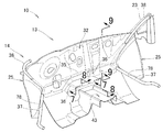
図1は本発明に係る車体前部構造の斜視図であり、図2は図1に示される車体前部構造の車室側からのダッシュボードパネル廻りの斜視図である。
The best mode for carrying out the present invention will be described below with reference to the accompanying drawings. The drawings are viewed in the direction of the reference numerals.
FIG. 1 is a perspective view of a vehicle body front structure according to the present invention, and FIG. 2 is a perspective view around a dashboard panel from the passenger compartment side of the vehicle body front structure shown in FIG.
車体10Aは、エンジンルーム21と車室22とを隔てるダッシュボードパネル(ダッシュボード)13と、このダッシュボードパネル13から車体前方向に延ばされる左右のフロントサイドフレーム11,11と、ダッシュボードパネル13の中央部から車体後方に延ばされるセンタトンネル(フロアトンネル)43と、ダッシュボードパネル13の側方から車体後方に延ばされる左右のサイドシル17,17(一方不図示)と、ダッシュボードパネル13の側方から斜め上方に延ばされるAピラー(フロントピラー)23,23(一方不図示)と、ダッシュボードパネル13から車体後方に延ばされる車体フロア(フロントフロア)15とを備える。
The
フロントサイドフレーム11,11は、車体幅方向に所定間隔をおいて配置され、車体前後方向に延出され、ダッシュボードパネル13に水平部後端(後端部)11aが接合される。
サイドシル17は、車室22の下部で左右端に設けられ車体フロア15を支持する骨格部材であり、サイドシルインナ45と、サイドシルアウタ46とからなり、前部17aがダッシュボードパネル13に接合される。
Aピラー(フロントピラー)23は、ダッシュボードパネル13の左右から車体後方に且つ斜め上方に延出される。
The
The
The A pillar (front pillar) 23 extends rearward and obliquely upward from the left and right sides of the
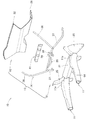
図3は図1に示される車体前部構造のダッシュボードパネルの分解斜視図であり、図4はダッシュパネル後分割体を取り除いたダッシュボードパネルの斜視図である。
ダッシュボードパネル13は、エンジンルーム21側に配置されるダッシュパネル前分割体61と、車室22側に配置されるダッシュパネル後分割体62と、これらのダッシュパネル前分割体61及びダッシュパネル後分割体62の間に、連結材(支持部材)41を介して配置される補強フレーム構造体(連結部材若しくはボード補強部材)14とからなる。
なお、連結材41は、ダッシュパネル後分割体62と補強フレーム構造体14との間に配置される。
FIG. 3 is an exploded perspective view of the dashboard panel of the vehicle body front structure shown in FIG. 1, and FIG. 4 is a perspective view of the dashboard panel with the rear divided body of the dashboard panel removed.
The
The connecting
ダッシュパネル前分割体61は、左右のフロントサイドフレーム11,11が車体前方に延出されるフロントサイドフレーム遮蔽部材(前ボードパネル)31と、このフロントサイドフレーム遮蔽部材31の中央下部から後方に延出され、センタトンネル43を接続するダッシュボード下部パネル(トンネル部補強板)64と、フロントサイドフレーム遮蔽部材31の両側に設けられ、前輪(不図示)を囲う左右のホイールアーチ部25,25とからなる。
The dash panel front divided
ダッシュパネル後分割体62は、車体10Aをエンジンルーム21側と車室22側と隔てる中央パネル(後ボードパネル)32と、この中央パネル32の両側下部に設けられ、左右のサイドシル17,17に接続する下サイドパネル(ダッシュボードパネル下部)28,28とからなる。
The
補強フレーム構造体(連結部材)14は、左右のサイドフレーム間を結合するクロスメンバ(中央連結部材)35と、サイドシル17,17の前部17a,17aを補強するサイドシル補強フレーム(ホイールアーチ下連結部材)37,37と、Aピラー23を補強するピラー補強フレーム(ホイールアーチ上連結部材)38,38と、センタトンネル43を補強するトンネル補強フレーム(トンネルフレーム連結部材)36,36と、からなり、クロスメンバ35をベースに一体化されたものである。
The reinforcing frame structure (connecting member) 14 includes a cross member (center connecting member) 35 that connects the left and right side frames, and a side sill reinforcing frame (connecting under the wheel arch) that reinforces the
クロスメンバ35及び左右のサイドシル補強フレーム37,37は、一本のパイプ部材を曲げ形成して形成される部分であり、サイドシル補強フレーム37,37は、ダッシュボードパネル13を通過させて(貫通させて)略直線状に形成され、クロスメンバ35は、ダッシュボードパネル13内を通過させて(貫通させて)略直線状に形成される。
The
ピラー補強フレーム38,38は、サイドシル補強フレーム37,37の根本にパイプ部材が溶接されたものであり、ダッシュパネル後分割体62を通過させて(貫通させて)、略直線状に形成される。
トンネル補強フレーム36,36は、クロスメンバ35にパイプ部材が溶接されたものである。
The
The
図5は図1に示される車体前部構造の補強フレーム構造体を模式的に表した斜視図である。
さらに、車体前部構造10では、ピラー補強フレーム38とサイドシル補強フレーム37とで、二股状の補強部材72が構成され、ピラー補強フレーム38とサイドシル補強フレーム37との交差する点を交差部73と呼ぶときに、二股状の補強部材72は、交差部73の交差角度θが60度に設定される。
FIG. 5 is a perspective view schematically showing the reinforcing frame structure of the vehicle body front structure shown in FIG.
Further, in the vehicle
Aピラー下部の取付点74とサイドシルの取付点75とを仮想線76で結ぶときに、交差部73、Aピラー下部の取付点74及びサイドシルの取付点75で略正三角形を形成される。なお、交差部73はクロスメンバ35に連結され、クロスメンバ35及びフロントサイドフレーム遮蔽部材31を介してフロントサイドフレーム11に取付けるフロントサイドフレーム内面の取付点でもある。
When the
図6は図1の6−6線断面図であり、図7は図2の7−7線断面図であり、図8は図2の8−8線断面図であり、図9は図2の9−9線断面図であり、図10は図9に示されたダッシュボードパネル廻りの溶接箇所を示す説明図である。なお、図6〜図8及び図10において黒丸印は溶接箇所を示す。 6 is a sectional view taken along line 6-6 in FIG. 1, FIG. 7 is a sectional view taken along line 7-7 in FIG. 2, FIG. 8 is a sectional view taken along line 8-8 in FIG. FIG. 10 is a cross-sectional view taken along line 9-9, and FIG. 10 is an explanatory view showing welded portions around the dashboard panel shown in FIG. In FIGS. 6 to 8 and 10, black circles indicate welding locations.
図6に示されるように、車体前部構造10では、ダッシュパネル前分割体61のホイールアーチ部25と補強フレーム構造体14のサイドシル補強フレーム37が溶接され、ホイールアーチ部25とダッシュパネル後分割体62の下サイドパネル28とが溶接され、この下サイドパネル28に中央パネル32及びサイドシル17が溶接されている。
As shown in FIG. 6, in the vehicle
すなわち、サイドシル補強フレーム37は、ダッシュパネル前分割体61のホイールアーチ部25の外周縁78(図2参照)に固定(連結)されるとともに、下サイドパネル(ダッシュボードパネル下部)28で覆われる(被覆される)。
That is, the side
図7に示されたように、車体前部構造10では、ダッシュパネル前分割体61のダッシュボード下部パネル64にダッシュパネル後分割体62の中央パネル32が溶接され、補強フレーム構造体14のトンネル補強フレーム36がダッシュボード下部パネル64及び中央パネル32に溶接され、さらに、中央パネル32は、アルミニウム鋳造継手部材65で補強されている。
As shown in FIG. 7, in the vehicle
図8に示されたように、車体前部構造10では、補強フレーム構造体14のトンネル補強フレーム36は、ダッシュパネル前分割体61のフロントサイドフレーム遮蔽部材31の後面31aに溶接(接合)されるとともに、ダッシュパネル前分割体61のダッシュボード下部パネル64とダッシュパネル後分割体62の中央パネル32との間を貫通させて、センタトンネル(トンネル部パネル)43の上部43a裏面に接合される。なお、補強フレーム構造体14のクロスメンバ35も、フロントサイドフレーム遮蔽部材31の後面31aに溶接(接合)されている。
As shown in FIG. 8, in the vehicle
図9及び図10に示されたように、車体前部構造10では、ダッシュパネル後分割体62の中央パネル32に連結材41が溶接されるとともに、ダッシュパネル前分割体61のフロントサイドフレーム遮蔽部材31が溶接され、フロントサイドフレーム遮蔽部材31にも連結材41が溶接され、フロントサイドフレーム遮蔽部材31にフロントサイドフレーム11が溶接され、フロントサイドフレーム遮蔽部材31及び連結材41に補強フレーム構造体14のクロスメンバ35が溶接される。
As shown in FIGS. 9 and 10, in the vehicle
すなわち、クロスメンバ(中央連結部材)35は、フロントサイドフレーム遮蔽部材31に固定されるとともに、連結材41を介してフロントサイドフレーム遮蔽部材31と中央パネル32とで挟み込まれたものである。
That is, the cross member (center connecting member) 35 is fixed to the front side
車体前部構造10の組立方法を説明する。
車体前部構造10では、図4に示されたように、ダッシュボードパネル13のホイールアーチ部25とフロントサイドフレーム遮蔽部材31を一体に形成したダッシュパネル前分割体61にサイドシル17,17、センタトンネル43及びAピラー23,23に繋がる補強フレーム構造体(連結部材)14を結合し、ダッシュパネル前分割体61及び補強フレーム構造体14の組立体79を作成する。このときに、補強フレーム構造体14のサイドシル補強フレーム37をホイールアーチ部25の外周縁78に沿わせて固定する。
A method for assembling the vehicle
In the vehicle
次に、組立体79を、図2に示されたように、フロントサイドフレーム11,11(図5参照)の水平部後端11aに嵌合し、組立体79に補強フレーム構造体14を押さえる連結材41を介在させてダッシュパネル後分割体62の中央パネル32を被せ、サイドシル補強フレーム37をホイールアーチ部25に接合する。
さらに、中央パネル32の下部に、フロントサイドフレーム11,11の車体フロア15下へ傾斜する部分(不図示)を接合する。
Next, as shown in FIG. 2, the
Further, a portion (not shown) of the front side frames 11, 11 that is inclined below the
補強フレーム構造体14のサイドシル補強フレーム37をサイドシル17へ直接結合し、その後に、車室22側から下サイドパネル(ダッシュボードパネル下部)28を被せ、ダッシュパネル前分割体61のホイールアーチ部25と、ダッシュパネル後分割体62の中央パネル32と接合する。
The side
図11(a),(b)は図1に示される車体前部構造のダッシュボードパネルの比較検討図である。
(a)において、比較例の車体前部構造100では、ダッシュボードパネル101にフロントサイドフレーム102を接続するだけの構造なので、フロントサイドフレーム102に矢印a1の如く荷重が作用したときには、ダッシュボードパネル101のホイールアーチ部103までの広範囲に亘って変形される。
11 (a) and 11 (b) are comparative study diagrams of the dashboard panel of the vehicle body front structure shown in FIG.
In (a), in the vehicle
(b)において、実施例の車体前部構造10では、ダッシュボードパネル13にフロントサイドフレーム11を補強フレーム構造体(連結部材)14を介して接続した構造なので、フロントサイドフレーム11に矢印a2の如く荷重が作用したときには、ダッシュボードパネル13の変形範囲は限られたものとなり、荷重がサイドシル17やAピラー23(図1,2参照)に円滑に伝達される。
In (b), in the vehicle body
例えば、(a)において、変形を受けるダッシュボードパネル101のフロントサイドフレーム102からホイールアーチ部103までの水平距離をL1とし、(b)において、変形を受けるダッシュボードパネル13のフロントサイドフレーム11からホイールアーチ部25までの水平距離をL2とすれば、L1>L2の関係になる。
For example, in (a), the horizontal distance from the
図4及び図9に示されたように、補強フレーム構造体(連結部材)14でフロントサイドフレーム11とホイールアーチ部25を接続することで、補強フレーム構造体(連結部材)14でホイールアーチ部25に支持点(境界)を作ることができる。これにより、ダッシュボードパネル13の撓みを防止することができる。すなわち、入力点と支持点(反力点)との距離を短く設定することができ、フロントサイドフレーム11の荷重(入力)に対する撓み量を少なくすることができる。
As shown in FIGS. 4 and 9, by connecting the
補強フレーム構造体(連結部材)14でフロントサイドフレーム11とサイドシル17を接続することで、補強フレーム構造体14が直接フロントサイドフレーム11からの荷重をサイドシル17へ伝えるとともに、ダッシュボードパネル13のホイールアーチ部25を支えて、ホイールアーチ部25の変形を防止できる。この結果、ダッシュボードパネル13の荷重伝達量も向上を図ることができ、レイアウトを犠牲にせずに、衝突性能と車体剛性との向上を図ることができる。
By connecting the
車体前部構造10では、エンジンルーム21と車室22とを隔てるダッシュボードパネル13が設けられ、このダッシュボードパネル13から車体前方に延ばされるフロントサイドフレーム11が設けられ、ダッシュボードパネル13から車体後方に延ばされるサイドシル17が設けられる。
In the vehicle
フロントサイドフレーム11の水平部後端11aとサイドシル17の前部17aとを、ダッシュボードパネル13内を貫通させて直線状に連結する補強フレーム構造体(連結部材)14を有するので、フロントサイドフレーム11からの荷重を直接サイドシル17へ伝達することができる。この結果、フロントサイドフレーム11からの荷重をサイドシル17へ円滑に伝達することができる。
Since the
補強フレーム構造体(連結部材)14をダッシュボードパネル13内を貫通させたので、車体前部のレイアウトの自由度を確保することができるとともに、車室22内のスペースを十分に確保することができる。
Since the reinforcing frame structure (connecting member) 14 is penetrated through the
車体前部構造10では、ダッシュボードパネル13の部位の中でもホイールアーチ部25はアーチ状に形成された剛性が高い部分であり、補強フレーム構造体(連結部材)14が、ダッシュボードパネル13のホイールアーチ部25の外周縁78の一部に固定されたので、ダッシュボードパネル13の撓み量を低減することができる。
In the vehicle
補強フレーム構造体(連結部材)14は、ダッシュボードパネル13のホイールアーチ部25に連結するとともにフロントサイドフレーム11が延出するフロントサイドフレーム遮蔽部材31に固定され、ダッシュボードパネル13の中央パネル32で挟まれたので、補強フレーム構造体(連結部材)14を、ダッシュボードパネル13内を貫通させることができる。この結果、ダッシュボードパネル13の効果的な補強を実現することができる。
The reinforcing frame structure (connecting member) 14 is connected to a wheel
補強フレーム構造体(連結部材)14のホイールアーチ部25側は、下サイドパネル(ダッシュボードパネル下部)28により被覆されたので、連結部材とホイールアーチ部25との結合の相乗効果により、さらなるダッシュボードパネル13の剛性の向上を図ることができる。また、補強フレーム構造体(連結部材)14とサイドシル17との結合が容易となる。
Since the wheel
尚、本発明に係る車体前部構造は、図4に示すように、補強フレーム構造体(連結部材)14は、クロスメンバ35及び左右のサイドシル補強フレーム37,37が一体的に形成され、左右のサイドシル補強フレーム37,37に左右のピラー補強フレーム38,38が溶接されたが、これに限るものではなく、クロスメンバ35及び左右のピラー補強フレームが一体的に形成され、左右のピラー補強フレームに左右のサイドシル補強フレームが溶接される形態であってもよい。
In the vehicle body front structure according to the present invention, as shown in FIG. 4, the reinforcing frame structure (connecting member) 14 is integrally formed with a
本発明に係る車体前部構造は、セダンやワゴンなどの乗用車に採用するのに好適である。 The vehicle body front structure according to the present invention is suitable for use in passenger cars such as sedans and wagons.
10…車体前部構造、11…フロントサイドフレーム、11a…水平部後端、13…ダッシュボードパネル、14…連結部材(補強フレーム構造体)、17…サイドシル、17a…前部、21…エンジンルーム、22…車室、25…ホイールアーチ部、28…ダッシュボードパネル下部(下サイドパネル)、31…フロントサイドフレーム遮蔽部材、32…中央パネル。
DESCRIPTION OF
Claims (4)
前記補強フレーム構造体は、パイプであって、前記左右のフロントサイドフレーム間を結合する略直線状のクロスメンバと、該クロスメンバの両端から二股状に分岐され、前記サイドシルの前部を連結する略直線状のサイドシル補強フレーム及び前記フロントピラーを連結する略直線状のピラー補強フレームと、を備え、
前記ダッシュボードパネルを、ダッシュパネル前分割体とダッシュパネル後分割体とに前後に分割し、前記ダッシュパネル前分割体と前記ダッシュパネル後分割体とで前記クロスメンバを挟み、該クロスメンバを前記ダッシュボードパネル内に配置し、
前記フロントサイドフレームの水平部後端と前記サイドシルの前部とを、前記ダッシュボードパネル内を貫通させた前記サイドシル補強フレームとで連結したことを特徴とする車体前部構造。 And dashboards panel separating the engine compartment and passenger compartment, and left and right front side frames extending from the dashboard panel in front of the vehicle body, and a side sill which is extended to the rear of the vehicle body from the dashboard panel, the side of the dashboard panel from the front pillar to be extended obliquely upwardly, said a vehicle body front structure having a reinforcing frame structure disposed on the dashboard panel, and
The reinforcing frame structure is a pipe that is bifurcated from both ends of the substantially straight cross member that connects the left and right front side frames, and connects the front portion of the side sill. A substantially linear side sill reinforcing frame and a substantially linear pillar reinforcing frame connecting the front pillar,
The dashboard panel is divided back and forth into a dash panel front divided body and a dash panel rear divided body, and the cross member is sandwiched between the dash panel front divided body and the dash panel rear divided body. Place it in the dashboard panel,
A vehicle body front part structure in which a horizontal rear end of the front side frame and a front part of the side sill are connected with the side sill reinforcing frame penetrating through the dashboard panel.
前記サイドシル補強フレームは、前記ホイールアーチ部の外周縁に固定されたことを特徴とする請求項1記載の車体前部構造。 The dash panel front divided body has a wheel arch part,
Front body structure of claim 1, wherein said side sill reinforcing frame, characterized in that fixed to the outer peripheral edge of the front Kiho Iruachi unit.
前記クロスメンバは、前記フロントサイドフレームが延出される前記ダッシュパネル前分割体の前記フロントサイドフレーム遮蔽部材に固定され、且つ該フロントサイドフレーム遮蔽部材と前記ダッシュパネル後分割体の中央パネルとで挟まれたことを特徴とする請求項1記載の車体前部構造。 Said side sill reinforcing frame, as well as connected to the front Kiho Iruachi unit,
In the cross member, the front side frame is fixed to the front side frame covering member of said dash panel front split body that will be extended, and the central panel of the with the front side frame covering member dash panel after divided member The vehicle body front part structure according to claim 1, wherein the vehicle body front part structure is sandwiched.
Priority Applications (3)
| Application Number | Priority Date | Filing Date | Title |
|---|---|---|---|
| JP2008279575A JP4677025B2 (en) | 2008-10-30 | 2008-10-30 | Body front structure |
| CN2009101792172A CN101722993B (en) | 2008-10-30 | 2009-10-10 | Front vehicle body structure |
| US12/608,385 US8029046B2 (en) | 2008-10-30 | 2009-10-29 | Front vehicle body structure |
Applications Claiming Priority (1)
| Application Number | Priority Date | Filing Date | Title |
|---|---|---|---|
| JP2008279575A JP4677025B2 (en) | 2008-10-30 | 2008-10-30 | Body front structure |
Publications (2)
| Publication Number | Publication Date |
|---|---|
| JP2010105532A JP2010105532A (en) | 2010-05-13 |
| JP4677025B2 true JP4677025B2 (en) | 2011-04-27 |
Family
ID=42130489
Family Applications (1)
| Application Number | Title | Priority Date | Filing Date |
|---|---|---|---|
| JP2008279575A Expired - Fee Related JP4677025B2 (en) | 2008-10-30 | 2008-10-30 | Body front structure |
Country Status (3)
| Country | Link |
|---|---|
| US (1) | US8029046B2 (en) |
| JP (1) | JP4677025B2 (en) |
| CN (1) | CN101722993B (en) |
Families Citing this family (21)
| Publication number | Priority date | Publication date | Assignee | Title |
|---|---|---|---|---|
| US8485591B2 (en) * | 2010-05-10 | 2013-07-16 | Honda Motor Co., Ltd. | Front vehicle body structure |
| WO2011148747A1 (en) * | 2010-05-25 | 2011-12-01 | 本田技研工業株式会社 | Structure for vehicle body front portion |
| JP5560329B2 (en) * | 2010-06-10 | 2014-07-23 | 本田技研工業株式会社 | Body front structure |
| CN102947169A (en) * | 2010-06-24 | 2013-02-27 | 本田技研工业株式会社 | Structure of front section of vehicle |
| JP5222374B2 (en) * | 2011-01-20 | 2013-06-26 | 本田技研工業株式会社 | Body front structure |
| JP5963036B2 (en) * | 2011-11-10 | 2016-08-03 | スズキ株式会社 | Dash panel structure |
| JP5928869B2 (en) * | 2011-11-29 | 2016-06-01 | スズキ株式会社 | Dash cross member mounting structure at the front of the vehicle body |
| DE102011089153A1 (en) * | 2011-12-20 | 2013-06-20 | Bayerische Motoren Werke Aktiengesellschaft | Structure for a motor vehicle, in particular a passenger car, and method for producing such a structure |
| DE102011089158A1 (en) * | 2011-12-20 | 2013-06-20 | Bayerische Motoren Werke Aktiengesellschaft | Structure for a motor vehicle, in particular a passenger car |
| JP6066315B2 (en) * | 2013-05-09 | 2017-01-25 | スズキ株式会社 | Vehicle front structure |
| US9233720B2 (en) * | 2013-06-28 | 2016-01-12 | GM Global Technology Operations LLC | Optimized high strength lateral beam system |
| US20150001876A1 (en) * | 2013-06-28 | 2015-01-01 | GM Global Technology Operations LLC | Secondary dash and methods of making and using the same |
| CN103770845B (en) * | 2014-01-26 | 2016-12-07 | 浙江吉利控股集团有限公司 | Strengthen the front deck internal structure of vehicle passenger compartment's front panel |
| JP6522982B2 (en) * | 2015-02-18 | 2019-05-29 | 本田技研工業株式会社 | Body structure |
| JP6237676B2 (en) * | 2015-03-03 | 2017-11-29 | トヨタ自動車株式会社 | Vehicle side structure |
| KR101664065B1 (en) * | 2015-03-17 | 2016-10-10 | 현대자동차 주식회사 | Front vehicle body reinforcing structure and assembling method thereof |
| CN108001541A (en) * | 2017-03-31 | 2018-05-08 | 长城汽车股份有限公司 | Vehicle body and vehicle |
| CN108001543A (en) * | 2017-03-31 | 2018-05-08 | 长城汽车股份有限公司 | Vehicle body and vehicle |
| CN108001537A (en) * | 2017-03-31 | 2018-05-08 | 长城汽车股份有限公司 | Vehicle body and vehicle |
| JP7255336B2 (en) * | 2019-04-18 | 2023-04-11 | スズキ株式会社 | Body front structure |
| JP7247853B2 (en) * | 2019-10-16 | 2023-03-29 | マツダ株式会社 | car body structure |
Citations (1)
| Publication number | Priority date | Publication date | Assignee | Title |
|---|---|---|---|---|
| JP2004067082A (en) * | 2002-08-02 | 2004-03-04 | Dr Ing H C F Porsche Ag | Body structure of passenger car |
Family Cites Families (17)
| Publication number | Priority date | Publication date | Assignee | Title |
|---|---|---|---|---|
| US3292969A (en) * | 1964-06-05 | 1966-12-20 | Budd Co | Tubular frame unitized body structure |
| JPS6313868A (en) * | 1986-07-04 | 1988-01-21 | Mazda Motor Corp | Lower body structure of automobile |
| DE4422498C1 (en) * | 1994-06-28 | 1995-10-19 | Porsche Ag | Body structure of a passenger car |
| JPH08175429A (en) * | 1994-12-27 | 1996-07-09 | Nissan Motor Co Ltd | Front part structure of car body |
| DE19642833C2 (en) * | 1996-10-17 | 2002-04-11 | Daimler Chrysler Ag | Front wall frame for a self-supporting body of a passenger car and method for its production |
| US6085859A (en) * | 1998-05-01 | 2000-07-11 | Alderson; Mark L. | Race car |
| JP3360647B2 (en) * | 1998-09-16 | 2002-12-24 | トヨタ自動車株式会社 | Car body front structure |
| KR100361299B1 (en) * | 2000-11-01 | 2002-11-22 | 현대자동차주식회사 | An automotive front reinforcement structure for distributing impact force |
| US6371767B1 (en) * | 2001-02-05 | 2002-04-16 | The United States Of America Government As Represented By The Secretary Of The Army | Demonstrator for new automotive technologies |
| CA2460902C (en) * | 2001-10-02 | 2010-12-21 | Magna International Inc. | Truck cab space frame |
| JP4000951B2 (en) * | 2002-08-13 | 2007-10-31 | 三菱自動車エンジニアリング株式会社 | Auto body front structure |
| JP3786093B2 (en) * | 2003-02-07 | 2006-06-14 | 日産自動車株式会社 | Body front structure |
| JP4329469B2 (en) * | 2003-09-29 | 2009-09-09 | マツダ株式会社 | Front body structure of the vehicle |
| US7942447B2 (en) * | 2004-12-30 | 2011-05-17 | American Off-Road Technologies, Llc | Frame design for reduced-size vehicle |
| US7441830B2 (en) * | 2005-06-08 | 2008-10-28 | Ford Global Technologies, Llc | Dual tube lower frame midrail structure |
| DE102006055721A1 (en) * | 2006-11-25 | 2008-05-29 | Dr.Ing.H.C. F. Porsche Ag | Motor vehicle with end wall cross member |
| EP2957271A1 (en) * | 2008-10-28 | 2015-12-23 | Darco Trust | Modular vehicle and triangular truss support system therefor |
-
2008
- 2008-10-30 JP JP2008279575A patent/JP4677025B2/en not_active Expired - Fee Related
-
2009
- 2009-10-10 CN CN2009101792172A patent/CN101722993B/en not_active Expired - Fee Related
- 2009-10-29 US US12/608,385 patent/US8029046B2/en not_active Expired - Fee Related
Patent Citations (1)
| Publication number | Priority date | Publication date | Assignee | Title |
|---|---|---|---|---|
| JP2004067082A (en) * | 2002-08-02 | 2004-03-04 | Dr Ing H C F Porsche Ag | Body structure of passenger car |
Also Published As
| Publication number | Publication date |
|---|---|
| US20100109370A1 (en) | 2010-05-06 |
| CN101722993B (en) | 2011-08-10 |
| US8029046B2 (en) | 2011-10-04 |
| CN101722993A (en) | 2010-06-09 |
| JP2010105532A (en) | 2010-05-13 |
Similar Documents
| Publication | Publication Date | Title |
|---|---|---|
| JP4677025B2 (en) | Body front structure | |
| JP3976198B2 (en) | Body front structure | |
| JP3962003B2 (en) | Body structure | |
| US9162708B2 (en) | Steering hanger assembly for vehicle | |
| JP4853080B2 (en) | Auto body structure | |
| JP5075949B2 (en) | Body front structure | |
| JP4483592B2 (en) | Dash panel reinforcement structure | |
| JP5478724B2 (en) | Body front structure | |
| JP4485992B2 (en) | Steering column mounting structure | |
| JP5533518B2 (en) | Car steering support member reinforcement structure | |
| JP3976199B2 (en) | Body structure | |
| JP4923406B2 (en) | Body front structure | |
| JP2008230459A (en) | Lower body structure of vehicle | |
| JP7095476B2 (en) | Vehicle front structure | |
| JP5150452B2 (en) | Body front structure | |
| JP2009040127A (en) | Front vehicle body structure of automobile | |
| JP5557867B2 (en) | Body front structure | |
| JP4485993B2 (en) | Steering hanger beam mounting structure | |
| JP3889741B2 (en) | Body structure | |
| JP2010105536A (en) | Vehicle front body structure | |
| JP6101722B2 (en) | Car body front support | |
| JP5145376B2 (en) | Body front structure | |
| JP6521428B2 (en) | Support for the front of the cabin | |
| JP6521427B2 (en) | Support for the front of the cabin | |
| JP5472995B2 (en) | Body structure in vehicles |
Legal Events
| Date | Code | Title | Description |
|---|---|---|---|
| A977 | Report on retrieval |
Free format text: JAPANESE INTERMEDIATE CODE: A971007 Effective date: 20100729 |
|
| A131 | Notification of reasons for refusal |
Free format text: JAPANESE INTERMEDIATE CODE: A131 Effective date: 20100907 |
|
| A521 | Written amendment |
Free format text: JAPANESE INTERMEDIATE CODE: A523 Effective date: 20100921 |
|
| TRDD | Decision of grant or rejection written | ||
| A01 | Written decision to grant a patent or to grant a registration (utility model) |
Free format text: JAPANESE INTERMEDIATE CODE: A01 Effective date: 20110125 |
|
| A01 | Written decision to grant a patent or to grant a registration (utility model) |
Free format text: JAPANESE INTERMEDIATE CODE: A01 |
|
| A61 | First payment of annual fees (during grant procedure) |
Free format text: JAPANESE INTERMEDIATE CODE: A61 Effective date: 20110128 |
|
| FPAY | Renewal fee payment (event date is renewal date of database) |
Free format text: PAYMENT UNTIL: 20140204 Year of fee payment: 3 |
|
| R150 | Certificate of patent or registration of utility model |
Free format text: JAPANESE INTERMEDIATE CODE: R150 |
|
| LAPS | Cancellation because of no payment of annual fees |