JP4112685B2 - Car front pillar - Google Patents
Car front pillar Download PDFInfo
- Publication number
- JP4112685B2 JP4112685B2 JP15569998A JP15569998A JP4112685B2 JP 4112685 B2 JP4112685 B2 JP 4112685B2 JP 15569998 A JP15569998 A JP 15569998A JP 15569998 A JP15569998 A JP 15569998A JP 4112685 B2 JP4112685 B2 JP 4112685B2
- Authority
- JP
- Japan
- Prior art keywords
- front pillar
- impact
- frame
- inner frame
- obstacle
- Prior art date
- Legal status (The legal status is an assumption and is not a legal conclusion. Google has not performed a legal analysis and makes no representation as to the accuracy of the status listed.)
- Expired - Fee Related
Links
Images


Classifications
-
- B—PERFORMING OPERATIONS; TRANSPORTING
- B62—LAND VEHICLES FOR TRAVELLING OTHERWISE THAN ON RAILS
- B62D—MOTOR VEHICLES; TRAILERS
- B62D21/00—Understructures, i.e. chassis frame on which a vehicle body may be mounted
- B62D21/15—Understructures, i.e. chassis frame on which a vehicle body may be mounted having impact absorbing means, e.g. a frame designed to permanently or temporarily change shape or dimension upon impact with another body
-
- B—PERFORMING OPERATIONS; TRANSPORTING
- B62—LAND VEHICLES FOR TRAVELLING OTHERWISE THAN ON RAILS
- B62D—MOTOR VEHICLES; TRAILERS
- B62D25/00—Superstructure or monocoque structure sub-units; Parts or details thereof not otherwise provided for
- B62D25/04—Door pillars ; windshield pillars
-
- B—PERFORMING OPERATIONS; TRANSPORTING
- B60—VEHICLES IN GENERAL
- B60R—VEHICLES, VEHICLE FITTINGS, OR VEHICLE PARTS, NOT OTHERWISE PROVIDED FOR
- B60R19/00—Wheel guards; Radiator guards, e.g. grilles; Obstruction removers; Fittings damping bouncing force in collisions
- B60R2019/007—Means for adjusting or regulating the crash absorption capacity of the vehicle, e.g. when detecting an impending collision
-
- B—PERFORMING OPERATIONS; TRANSPORTING
- B60—VEHICLES IN GENERAL
- B60Y—INDEXING SCHEME RELATING TO ASPECTS CROSS-CUTTING VEHICLE TECHNOLOGY
- B60Y2306/00—Other features of vehicle sub-units
- B60Y2306/01—Reducing damages in case of crash, e.g. by improving battery protection
Landscapes
- Engineering & Computer Science (AREA)
- Chemical & Material Sciences (AREA)
- Combustion & Propulsion (AREA)
- Transportation (AREA)
- Mechanical Engineering (AREA)
- Body Structure For Vehicles (AREA)
Description
【0001】
【発明の属する技術分野】
本発明は自動車のフロントピラーの改良に関する。
【0002】
【従来の技術】
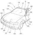
図7は自動車のフロント部分の斜視図であり、101,101はフロントフェンダ、102はボンネット、103はフロントマスク、104,104はヘッドライト、105はラジエータグリル、106はフロントバンパ、107は前輪、108はドアミラー、109はフロントガラス、111はドア、112はドアガラス、113はルーフ、120,120はサイドボデー、130,130はサイドボデー120,120の骨組の一部としてのフロントピラーである。
サイドボデー120,120は、自動車の車室121を形成する構造部材として、転覆時の車体の変形を抑えるとともに、耐久強度を確保する役割を担うものである。
【0003】
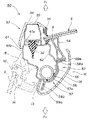
図8は図7A部の平面断面図であり、従来のフロントピラー130の拡大した平面断面図を示す。なお、Frは前側、Rrは後側を示す。
フロントピラー130は、インナフレーム132と、このインナフレーム132に被せたアウタフレーム133とからなる。
インナフレーム132は、板金を断面視で皿状に曲げ形成したものであって、皿状の凹部となる底面部132aを形成し、この底面部132aの両サイドにアウタフレームとの合せ面132b,132cを形成したものである。
アウタフレーム133は、板金を断面視で略U字形に曲げ形成したものであって、略U字形の凸部となる前面部133aを形成し、この前面部133aの両サイドにインナフレーム132との合せ面133b,133cを形成したものである。
【0004】
すなわち、フロントピラー130は、インナフレーム132の合せ面132bとアウタフレーム133の合せ面133bとを接合し、インナフレーム132の合せ面132cとアウタフレーム133の合せ面133cとを接合して断面視でパイプ状に形成したサイドボディ120(図7参照)の骨組の一部である。
134はドア側ウェザストリップ、135はドアサッシ、136は接着モール、137はウェザストリップ、138はシーラント、140は障害物である。
【0005】
フロントピラー130は、先に説明したようにサイドボデー120の構造部材の一部であるから剛性の高い部材であり、例えば、障害物140がアウタフレーム133の前面部133aに当った場合には、障害物140の衝撃が大きい。一方、障害物140の保護を優先するあまり、フロントピラー130の剛性を低くしたのでは転覆時の車体の変形を抑えるための耐久強度を確保することができない。
そこで、フロントピラー本来の剛性を維持しつつ障害物への衝撃を十分に緩和することのできる自動車のフロントピラーが望まれる。
【0006】
障害物への衝撃の緩和を配慮した自動車のフロントピラーとして、例えば特開平9−39833号公報「自動車のフロントピラー」が知られている。
上記技術は、同公報図1及び図2によれば、ピラーインナ6(符号は公報に記載の番号を使用した。)にピラーアウタ7を合せてピラー本体5を形成し、ピラーアウタ7の前面部分7aに緩衝パネル8を取付け、この緩衝パネル8の前面に樹脂ガーニッシュ9を取付けた自動車のフロントピラー1であり、このフロントピラー1は、ピラー本体5の前面に緩衝パネル8を取付けることで、障害物への衝撃を緩和しようとするものである。
【0007】
【発明が解決しようとする課題】
しかし、上記公報の技術は、図8に示した従来のフロントピラー構造に緩衝パネル8を設けただけのものであり、例えば、障害物が緩衝パネル8を介してピラー本体5に当った場合には、緩衝パネル8の変形で衝撃エネルギーを吸収するだけであり、障害物がピラー本体5まで到達した後の衝撃エネルギーの吸収手段がない。従って、障害物に対して十分な衝撃の緩和をすることができない。
すなわち、上記技術は、ピラー本体5にフロントピラー本来の剛性はあるものの、障害物が当ったときに、ピラー本体5自体で障害物への衝撃を緩和できるように配慮したものではない。
【0008】
そこで、本発明の目的は、フロントピラー本来の剛性を維持しつつ障害物への衝撃を十分に緩和することのできる自動車のフロントピラーを提供することにある。
【0009】
【課題を解決するための手段】
上記目的を達成するために請求項1は、車室に近接配置されたインナフレームと、車室から離間配置されたアウタパネルを有する筒型断面の自動車のフロントピラーにおいて、インナフレームの車室寄りに補強板を介して補強パイプが取付けられ、インナフレーム若しくはアウタパネルに、且つ補強パイプの車室と対向側に面する側に脆弱部が形成され、フロントピラーの、車室から離間して配置されたアウタパネルに自動車の外部から加えられた衝撃力により、インナフレーム若しくはアウタパネルが脆弱部で座屈して衝撃力が補強パイプに加わる前に衝撃エネルギーを吸収することを特徴とする。
フロントピラーに障害物が当ったときに、脆弱部でフロントピラーが変形し衝撃エネルギーを吸収して、障害物への衝撃を十分に緩和する。
フロントピラーの変形を促す脆弱部を自動車室内側に設けて、例えば、カバーなどで覆い脆弱部を外面から隠すようにする。
【0010】
請求項2は、フロントピラーの前面に平坦部を形成し、この平坦部に衝撃を吸収する保護部材を付設したことを特徴とする。
フロントピラーの前面に平坦部を形成し、この平坦部に衝撃を吸収する保護部材を突出させ、フロントピラーを変形させる前に、障害物のエネルギーを初期的に吸収させ、障害物の衝撃を効果的に抑える。
【0011】
請求項3は、フロントピラー内に衝撃を吸収する緩衝部材を介在させたことを特徴とする。
フロントピラー内に衝撃を吸収する緩衝部材を介在させ、フロントピラーの剛性の高い部分まで障害物が達するような場合に、フロントピラーの剛性の高い部分から障害物が受ける衝撃を最小限に止める。
【0012】
【発明の実施の形態】
本発明の実施の形態を添付図に基づいて以下に説明する。なお、「前」、「後」、「左」、「右」、「上」、「下」は運転者から見た方向に従い、Frは前側、Rrは後側を示す。また、図面は符号の向きに見るものとする。
図1は本発明に係る第1実施例の自動車のフロントピラーの平面断面図である。
フロントピラー1は、インナフレーム20と、このインナフレーム20に被せたアウタフレーム30とからなり、インナフレーム20にアウタフレーム30を被せることで断面視筒型に形成したものである。
【0013】
5はフロントガラス、6はウェザストリップ、7はシーラント、8はドアサッシ、9はドアガラス、12はドア外側ウェザストリップ、13はドア内側ウェザストリップ、14は窓用ウェザストリップ、15は室内側カバー、16は自動車室内としての車室である。
フロントガラス5は、合せガラスであり、2枚の生板ガラス5a,5bをポリビニルブチラールなどの透明樹脂フィルム5cを介して接着したものである。
室内側カバー15は、車室16の外観を向上すると共に、フロントピラー1に対してのプロテクタとしての機能を持つ。
【0014】
図2は本発明に係る第1実施例の自動車のフロントピラーの斜視図である。
インナフレーム20は、補強パイプ25と、この補強パイプ25に溶接又は接着で取付けた補強板26を介して取付けたフレーム部27とからなる。
詳細には、補強パイプ25は、インナフレーム20の芯材としての機能を果たし、補強板26は、フレーム部27のベース面27aの剛性を補填する役割を果たす。
フレーム部27は、板金を断面視で略U字形に曲げ形成したものであって、先に説明したベース面27aから一方に脆弱部としての曲げ部27bを介してアウタフレーム30に合せる合せ面28aを形成し、他方にアウタフレーム30に合せる合せ面28bを形成したものである。
【0015】
アウタフレーム30は、フレーム本体31と、このフレーム本体31に支持スナップ32…(…は複数個を示す。以下同じ。)を介して取付けた保護部材33と、この保護部材33に取付けた化粧フレーム34と、この化粧フレーム34の一端に取付けた接着モール36とからなる。
【0016】
詳細には、フレーム本体31は、インナフレーム20の構成部材であるフレーム部27の合せ面28aに取付ける合せ面39aから外方へ平坦部31aを延ばし、平坦部31aから後方へ外壁部31bを延ばし、この外壁部31bの先端にフレーム部27の合せ面28bに取付ける合せ面39bを形成したものである。平坦部31aは、支持スナップ32…を介して保護部材33を取付ける部分である。
保護部材33は、例えば、塩化ビニールなどの樹脂の押出し材で形成したものであり、フロント方向からの衝撃で変形が容易な材料で形成して、衝撃を吸収可能な部材である。
化粧フレーム34は、フロントピラー1の外観を向上すると共に、フロント方向からの衝撃で変形が容易な材料で形成した部材である。
【0017】
以上に述べたフロントピラー1の作用を次に説明する。なお、図4及び図5はフロントピラー1の変形の様子を模式的に表したものである。
図3(a),(b)は本発明に係る自動車の第1実施例のフロントピラーの作用説明図(前半)である。
(a)において、障害物Sが矢印▲1▼の如くフロントピラー1に当る。
(b)において、保護部材33が化粧フレーム34を介して矢印▲2▼の如く潰れ、障害物Sのエネルギーを初期的に吸収し、障害物Sの衝撃を効果的に抑える。化粧フレーム34は、フロント方向からの衝撃で変形が容易な材料で形成した部材であるから、保護部材33の変形の妨げにはならない。
【0018】
図4(a),(b)は本発明に係る自動車の第1実施例のフロントピラーの作用説明図(後半)である。
(a)において、さらに、障害物Sが矢印▲3▼の如くフロントピラー1に進入すると、車室16側に設けたインナフレーム20の構造部材であるフレーム部27の曲げ部27bが矢印▲4▼の如く容易に曲り、アウタフレーム30と共に後方に変形し衝撃エネルギーを吸収するため、障害物への衝撃を十分に緩和させることができる。
(b)は、障害物Sがフロントピラー1に矢印▲5▼の如く進入した最終的な姿を示し、フレーム部27の曲げ部27bが十分に変形し衝撃エネルギーを吸収するため、障害物への衝撃を十分に緩和することを示す。
フロントピラー1の変形を促す曲げ部27bを自動車の室内16側に設けて、室内側カバー15(図1参照)で覆い曲げ部27bを外面から隠すようにしたので、外観を損うことはない。
【0019】
図5は本発明に係る自動車の第2実施例のフロントピラーの平面断面図である。なお、図1に示すフロントピラー1と同一部品は同一符号を使用し詳細な説明を省略する。
フロントピラー40は、インナフレーム42と、このインナフレーム42に被せたアウタフレーム43と、これらのフレーム42,43の間に介在させた衝撃を吸収する緩衝部材44とからなる。
【0020】
インナフレーム42は、フレームの芯材となる補強パイプ45と、この補強パイプ45に補強板46を介して取付けたフレーム部47とからなる。
フレーム部47は、板金を断面視で略U字形に曲げ形成したものであって、先に説明したベース面47aから一方に脆弱部としてのV字部47bを介してアウタフレーム43の合せ面48aを形成し、他方にアウタフレーム43の合せ面48bを形成したものである。
フロントピラー40の変形を促すV字部47bを自動車の室内16側に設けて、室内側カバー15で覆いV字部47bを外面から隠すようにしたので、外観を損うことはない。
【0021】
アウタフレーム43は、インナフレーム42の構成部材であるフレーム部47の合せ面48aに取付ける合せ面49aから前方へ膨出部43aを形成し、この膨出部43bから後方へ外壁部43bを延ばし、この外壁部43bの先端にフレーム部47の合せ面48bに取付ける合せ面49bを形成したものである。なお、43cは膨出部43aに取付けた接着モールである。
緩衝部材44は、フロントピラー40の剛性の高い部分、すなわち、補強パイプ45や補強板46まで障害物S(図3参照)が達するような場合に、フロントピラー40の剛性の高い部分から障害物S(図3参照)が受ける衝撃を最小限に止めるためのものである。
【0022】
図6は本発明に係る自動車の第3実施例のフロントピラーの平面断面図である。なお、図1に示すフロントピラー1と同一部品は同一符号を使用し詳細な説明を省略する。
フロントピラー50は、インナフレーム52と、このインナフレーム52に被せたアウタフレーム53とからなる。なお、54はフロントガラス5を衝撃吸収効果を持たせて取付けるための可撓性のスペーサである。
インナフレーム52は、フレームの芯材となる補強パイプ55と、この補強パイプ55に補強板56を介して取付けたフレーム部57とからなる。
フレーム部57は、板金を断面視で略U字形に曲げ形成したものであって、先に説明したベース面57aから一方にアウタフレームに合せる合せ面58aを形成し、他方にアウタフレーム53に合せる合せ面58bを形成したものである。
【0023】
アウタフレーム53は、フレーム本体61と、このフレーム本体61に支持スナップ32…を介して取付けた第1実施例に示すところの保護部材33と、この保護部材33に取付けた化粧フレーム34と、この化粧フレーム34の一端に取付けた接着モール36とからなる。
詳細には、フレーム本体61は、インナフレーム52の構成部材であるフレーム部57の合せ面58aに取付ける合せ面59aから脆弱部としての曲げ部62を介して外方へ平坦部61aを延ばし、平坦部61aから後方へ外壁部61bを延ばし、この外壁部61bの先端にフレーム部57の合せ面58bに取付ける合せ面59bを形成したものである。
【0024】
フロントピラー50の変形を促す曲げ部62を自動車の室内16側に設けて、室内側カバー15で覆い曲げ部62を外面から隠すようにしたので、外観を損うことはない。
フロントガラス5を可撓性のスペーサ54を介してフロントピラー50に取付けたので、障害物S(図3参照)の一端がフロントガラス5に当った場合に、フロントガラス5によって受ける障害物S(図3参照)の衝撃を最小限に止めるものである。
【0025】
尚、第1〜第3実施例において、脆弱部としての曲げ部27b(図1参照)、V字部47b(図5参照)又は曲げ部62(図6参照)に変形を容易にする孔を形成して、曲げ部27、V字部47b又は曲げ部62を更に低剛性化したものであってもよい。
【0026】
【発明の効果】
本発明は上記構成により次の効果を発揮する。
請求項1は、車室に近接配置されたインナフレームと、車室から離間配置されたアウタパネルを有する筒型断面の自動車のフロントピラーにおいて、インナフレームの車室寄りに補強板を介して補強パイプが取付けられ、インナフレーム若しくはアウタパネルに、且つ補強パイプの車室と対向側に面する側に脆弱部が形成されたので、フロントピラーに障害物が当ったときに、脆弱部でフロントピラーが変形し衝撃エネルギーを吸収するため、障害物への衝撃を十分に緩和することができる。
フロントピラーの変形を促す脆弱部を自動車室内側に設けたので、例えば、カバーなどで覆い脆弱部を外面から隠すことができる。従って、自動車室内側の外観を損うことなく、脆弱部を形成することができる。
【0027】
請求項2は、フロントピラーの前面に平坦部を形成し、この平坦部に衝撃を吸収する保護部材を付設したので、フロントピラーを変形させる前に、障害物のエネルギーを初期的に吸収することができ、障害物の衝撃を効果的に抑えることができる。
【0028】
フロントピラー内に衝撃を吸収する緩衝部材を介在させたので、フロントピラーの剛性の高い部分まで障害物が達するような場合に、フロントピラーの剛性の高い部分から障害物が受ける衝撃を最小限に止めることができる。
【図面の簡単な説明】
【図1】本発明に係る第1実施例の自動車のフロントピラーの平面断面図
【図2】本発明に係る第1実施例の自動車のフロントピラーの斜視図
【図3】本発明に係る自動車の第1実施例のフロントピラーの作用説明図(前半)
【図4】本発明に係る自動車の第1実施例のフロントピラーの作用説明図(後半)
【図5】本発明に係る自動車の第2実施例のフロントピラーの平面断面図
【図6】本発明に係る自動車の第3実施例のフロントピラーの平面断面図
【図7】自動車のフロント部分の斜視図
【図8】図7A部の平面断面図
【符号の説明】
1,40,50…フロントピラー、16…自動車室内(車室)、27b…脆弱部(曲げ部)、31a,61a…平坦部、33…保護部材、44…緩衝部材、47b…脆弱部(V字部)、62…脆弱部(曲げ部)。[0001]
BACKGROUND OF THE INVENTION
The present invention relates to an improvement in a front pillar of an automobile.
[0002]
[Prior art]
FIG. 7 is a perspective view of a front part of an automobile, 101 and 101 are front fenders, 102 is a bonnet, 103 is a front mask, 104 and 104 are headlights, 105 is a radiator grill, 106 is a front bumper, 107 is a front wheel, 108 is a door mirror, 109 is a windshield, 111 is a door, 112 is a door glass, 113 is a roof, 120 and 120 are side bodies, and 130 and 130 are front pillars as part of the frame of the
The
[0003]
FIG. 8 is a plan sectional view of the portion of FIG. 7A, showing an enlarged plan sectional view of a conventional
The
The
The
[0004]
That is, the
[0005]
Since the
Therefore, a front pillar of an automobile that can sufficiently reduce the impact on an obstacle while maintaining the original rigidity of the front pillar is desired.
[0006]
Japanese Laid-Open Patent Publication No. 9-39833, “Automobile Front Pillar” is known as a front pillar of an automobile in consideration of mitigation of an impact on an obstacle.
According to FIGS. 1 and 2, the technique described above forms the
[0007]
[Problems to be solved by the invention]
However, the technique of the above publication is merely a
That is, although the above-described technique has the inherent rigidity of the front pillar in the
[0008]
Therefore, an object of the present invention is to provide a front pillar of an automobile that can sufficiently reduce an impact on an obstacle while maintaining the original rigidity of the front pillar.
[0009]
[Means for Solving the Problems]
In order to achieve the above object, a first aspect of the present invention provides a front pillar of an automobile having a cylindrical cross section having an inner frame disposed close to a passenger compartment and an outer panel spaced apart from the passenger compartment. A reinforcing pipe is attached via a reinforcing plate, a weak portion is formed on the inner frame or the outer panel and on the side facing the passenger compartment of the reinforcing pipe, and the front pillar is arranged away from the passenger compartment. The impact force applied to the outer panel from the outside of the vehicle is such that the inner frame or the outer panel buckles at the weak part and absorbs the impact energy before the impact force is applied to the reinforcing pipe .
When an obstacle hits the front pillar, the front pillar is deformed at the fragile portion to absorb the impact energy, and the impact on the obstacle is sufficiently mitigated.
A fragile portion that facilitates deformation of the front pillar is provided on the vehicle interior side, and is covered with, for example, a cover to hide the fragile portion from the outer surface.
[0010]
According to a second aspect of the present invention, a flat portion is formed on the front surface of the front pillar, and a protective member that absorbs an impact is attached to the flat portion.
A flat part is formed on the front surface of the front pillar, and a protective member that absorbs the impact is projected on the flat part. Before the front pillar is deformed, the energy of the obstacle is absorbed initially, and the impact of the obstacle is effective. Suppress it.
[0011]
According to a third aspect of the present invention, a shock absorbing member for absorbing an impact is interposed in the front pillar.
A shock absorbing member that absorbs impact is interposed in the front pillar, and when an obstacle reaches a portion having high rigidity of the front pillar, the impact received by the obstacle from the portion having high rigidity of the front pillar is minimized.
[0012]
DETAILED DESCRIPTION OF THE INVENTION
Embodiments of the present invention will be described below with reference to the accompanying drawings. Note that “front”, “rear”, “left”, “right”, “upper”, and “lower” follow the direction seen from the driver, Fr indicates the front side, and Rr indicates the rear side. The drawings are to be viewed in the direction of the reference numerals.
FIG. 1 is a plan sectional view of a front pillar of an automobile according to a first embodiment of the present invention.
The
[0013]
5 is a windshield, 6 is a weather strip, 7 is a sealant, 8 is a door sash, 9 is a door glass, 12 is a weather strip outside the door, 13 is a weather strip inside the door, 14 is a weather strip for windows, and 15 is an indoor cover.
The
The
[0014]
FIG. 2 is a perspective view of the front pillar of the automobile according to the first embodiment of the present invention.
The
Specifically, the reinforcing
The
[0015]
The
[0016]
Specifically, the frame
The
The
[0017]
Next, the operation of the
FIGS. 3A and 3B are operation explanatory views (first half) of the front pillar of the first embodiment of the automobile according to the present invention.
In (a), the obstacle S hits the
In (b), the
[0018]
4 (a) and 4 (b) are operation explanatory views (second half) of the front pillar of the first embodiment of the automobile according to the present invention.
In (a), when the obstacle S further enters the
(B) shows the final appearance of the obstacle S entering the
Since the
[0019]
FIG. 5 is a plan sectional view of the front pillar of the second embodiment of the automobile according to the present invention. The same parts as those of the
The
[0020]
The
The
Since the V-shaped
[0021]
The
When the obstacle S (see FIG. 3) reaches the highly rigid portion of the
[0022]
FIG. 6 is a plan sectional view of the front pillar of the third embodiment of the automobile according to the present invention. The same parts as those of the
The
The
The
[0023]
The
Specifically, the frame
[0024]
Since the bending
Since the
[0025]
In the first to third embodiments, a
[0026]
【The invention's effect】
The present invention exhibits the following effects by the above configuration.
According to a first aspect of the present invention, in the front pillar of an automobile having a cylindrical cross section having an inner frame arranged close to the passenger compartment and an outer panel spaced apart from the passenger compartment, a reinforcing pipe is disposed near the passenger compartment of the inner frame via a reinforcing plate. Is attached to the inner frame or outer panel, and the fragile part is formed on the side of the reinforcing pipe facing the passenger compartment, so the front pillar deforms at the fragile part when an obstacle hits the front pillar. Since the impact energy is absorbed, the impact on the obstacle can be sufficiently mitigated.
Since the fragile portion that promotes the deformation of the front pillar is provided on the vehicle interior side, the fragile portion can be hidden from the outer surface by being covered with, for example, a cover. Therefore, the fragile portion can be formed without deteriorating the appearance of the vehicle interior side.
[0027]
According to the second aspect of the present invention, a flat portion is formed on the front surface of the front pillar, and a protective member that absorbs an impact is attached to the flat portion, so that the energy of the obstacle is first absorbed before the front pillar is deformed. Can effectively suppress the impact of obstacles.
[0028]
Since a shock absorbing member is interposed in the front pillar, when an obstacle reaches the rigid part of the front pillar, the impact received by the obstacle from the highly rigid part of the front pillar is minimized. Can be stopped.
[Brief description of the drawings]
FIG. 1 is a plan sectional view of a front pillar of an automobile according to a first embodiment of the present invention. FIG. 2 is a perspective view of a front pillar of the automobile according to the first embodiment of the invention. Of the front pillar of the first embodiment of the present invention (first half)
FIG. 4 is an operation explanatory view of the front pillar of the first embodiment of the automobile according to the present invention (second half)
FIG. 5 is a plan sectional view of the front pillar of the second embodiment of the automobile according to the present invention. FIG. 6 is a sectional plan view of the front pillar of the third embodiment of the automobile according to the present invention. FIG. 8 is a cross-sectional plan view of FIG.
DESCRIPTION OF
Claims (3)
前記インナフレームの前記車室寄りに補強板を介して補強パイプが取付けられ、
前記インナフレーム若しくは前記アウタパネルに、且つ前記補強パイプの前記車室と対向側に面する側に脆弱部が形成され、
前記フロントピラーの、車室から離間して配置された前記アウタパネルに自動車の外部から加えられた衝撃力により、前記インナフレーム若しくは前記アウタパネルが前記脆弱部で座屈して前記衝撃力が前記補強パイプに加わる前に衝撃エネルギーを吸収することを特徴とする自動車のフロントピラー。 In the front pillar of an automobile with a cylindrical cross section having an inner frame arranged close to the passenger compartment and an outer panel spaced apart from the passenger compartment ,
A reinforcing pipe is attached to the inner frame near the vehicle compartment via a reinforcing plate,
A fragile portion is formed on the inner frame or the outer panel, and on the side of the reinforcing pipe facing the vehicle compartment ,
The inner frame or the outer panel is buckled at the fragile portion by the impact force applied from the outside of the automobile to the outer panel of the front pillar that is arranged away from the passenger compartment, and the impact force is applied to the reinforcing pipe. A front pillar of an automobile that absorbs impact energy before applying.
Priority Applications (8)
| Application Number | Priority Date | Filing Date | Title |
|---|---|---|---|
| JP15569998A JP4112685B2 (en) | 1998-06-04 | 1998-06-04 | Car front pillar |
| KR10-2000-7000877A KR100521756B1 (en) | 1998-06-04 | 1999-05-31 | Automobile front pillar |
| DE19981166T DE19981166B4 (en) | 1998-06-04 | 1999-05-31 | Auto front pillar |
| PCT/JP1999/002875 WO1999062755A1 (en) | 1998-06-04 | 1999-05-31 | Automobile front pillar |
| CN998009075A CN1131805C (en) | 1998-06-04 | 1999-05-31 | Automobile front pillar |
| GB0001331A GB2342077B (en) | 1998-06-04 | 1999-05-31 | Automobile front pillar |
| CA002297928A CA2297928C (en) | 1998-06-04 | 1999-05-31 | Automobile front pillar |
| US09/462,044 US6722729B2 (en) | 1998-06-04 | 1999-05-31 | Automobile front pillar |
Applications Claiming Priority (1)
| Application Number | Priority Date | Filing Date | Title |
|---|---|---|---|
| JP15569998A JP4112685B2 (en) | 1998-06-04 | 1998-06-04 | Car front pillar |
Publications (2)
| Publication Number | Publication Date |
|---|---|
| JPH11342863A JPH11342863A (en) | 1999-12-14 |
| JP4112685B2 true JP4112685B2 (en) | 2008-07-02 |
Family
ID=15611596
Family Applications (1)
| Application Number | Title | Priority Date | Filing Date |
|---|---|---|---|
| JP15569998A Expired - Fee Related JP4112685B2 (en) | 1998-06-04 | 1998-06-04 | Car front pillar |
Country Status (8)
| Country | Link |
|---|---|
| US (1) | US6722729B2 (en) |
| JP (1) | JP4112685B2 (en) |
| KR (1) | KR100521756B1 (en) |
| CN (1) | CN1131805C (en) |
| CA (1) | CA2297928C (en) |
| DE (1) | DE19981166B4 (en) |
| GB (1) | GB2342077B (en) |
| WO (1) | WO1999062755A1 (en) |
Families Citing this family (27)
| Publication number | Priority date | Publication date | Assignee | Title |
|---|---|---|---|---|
| US6739624B2 (en) | 1997-10-16 | 2004-05-25 | Magna International Inc. | Frame assembly for a motor vehicle |
| EP1106484B1 (en) * | 1999-11-30 | 2008-05-21 | Honda Giken Kogyo Kabushiki Kaisha | Vehicle front pillar |
| DE10001316B4 (en) * | 2000-01-14 | 2011-04-28 | Volkswagen Ag | A method of manufacturing a vehicle body and vehicle body having a mounting flange provided on frame portions |
| JP4360003B2 (en) * | 2000-04-12 | 2009-11-11 | トヨタ自動車株式会社 | Vehicle pillar structure |
| US6729425B2 (en) * | 2001-09-05 | 2004-05-04 | L&L Products, Inc. | Adjustable reinforced structural assembly and method of use therefor |
| DE10151684B4 (en) * | 2001-10-19 | 2005-10-06 | Daimlerchrysler Ag | Sidewall assembly for a motor vehicle body |
| DE10314035B4 (en) * | 2003-03-28 | 2011-08-11 | Dr. Ing. h.c. F. Porsche Aktiengesellschaft, 70435 | Hinge column of a motor vehicle body, in particular a body for a passenger car |
| US6979052B2 (en) * | 2003-09-09 | 2005-12-27 | Autoliv Asp, Inc. | Energy absorption bracket |
| DE102004009665B4 (en) * | 2004-02-27 | 2006-02-02 | Benteler Automobiltechnik Gmbh | A-pillar for a motor vehicle body |
| US7328421B1 (en) * | 2005-02-17 | 2008-02-05 | Xilinx, Inc. | Relocating blocks for netlist generation of an electronic system |
| FR2885583A1 (en) * | 2005-05-12 | 2006-11-17 | Livbag Soc Par Actions Simplif | DEVICE FOR REINFORCING HOLLOW BODY MEMBER AND CORRESPONDING METHOD |
| US8381403B2 (en) | 2005-05-25 | 2013-02-26 | Zephyros, Inc. | Baffle for an automotive vehicle and method of use therefor |
| FR2889503B1 (en) * | 2005-08-02 | 2007-09-14 | Peugeot Citroen Automobiles Sa | BAY END FOR A BODY STRUCTURE OF A MOTOR VEHICLE AND METHOD FOR ASSEMBLING SUCH A BAY AMOUNT |
| JP4422668B2 (en) * | 2005-10-19 | 2010-02-24 | ヤンマー株式会社 | Tractor loader backhoe frame structure |
| US7631928B2 (en) * | 2007-11-09 | 2009-12-15 | Toyota Motor Engineering & Manufacturing North America, Inc. | Vehicle hood reinforcement structures |
| FR2925425B1 (en) * | 2007-12-20 | 2009-12-11 | Renault Sas | SUPPORT OF ONE OR MORE ELEMENTS FOR FIXING ON A MOTOR VEHICLE STRUCTURE |
| CN103144677B (en) * | 2008-07-04 | 2016-03-09 | 本田技研工业株式会社 | The front pillar of automobile |
| FR2946309B1 (en) * | 2009-06-04 | 2011-06-10 | Peugeot Citroen Automobiles Sa | FRONT FOOT OF MOTOR VEHICLE COMPRISING A DEFORMABLE AREA IN CASE OF FRONTAL SHOCK AND VEHICLE EQUIPPED WITH SUCH FRONT FEET |
| DE102009057833B4 (en) * | 2009-12-10 | 2019-11-21 | Dr. Ing. H.C. F. Porsche Aktiengesellschaft | Device for holding a functional part, in particular a roof grab handle, in a vehicle |
| DE102011119105A1 (en) * | 2011-11-22 | 2013-05-23 | GM Global Technology Operations LLC (n. d. Gesetzen des Staates Delaware) | Motor car, has A-pillar for limiting windscreen aperture and windscreen, and edge area secured at A-pillar by intermediate piece, where intermediate piece is connected with A-pillar over set of corrodible weak points |
| US9481320B2 (en) * | 2014-08-07 | 2016-11-01 | Honda Motor Co., Ltd. | Front pillar exterior garnish for a vehicle body |
| US9187135B1 (en) | 2015-01-09 | 2015-11-17 | Nissan North America, Inc. | Vehicle body structure |
| US9248862B1 (en) | 2015-01-09 | 2016-02-02 | Nissan North America, Inc. | Vehicle body structure |
| JP6202028B2 (en) | 2015-03-24 | 2017-09-27 | トヨタ自動車株式会社 | Arrangement structure of surrounding information detection sensor and autonomous driving vehicle |
| US9598112B1 (en) * | 2015-12-07 | 2017-03-21 | Honda Motor Co., Ltd. | Front pillar for a vehicle body |
| CN106080791A (en) * | 2016-07-16 | 2016-11-09 | 李德生 | Transparent side-view type limit pod door frame and method of attachment |
| EP3665069B1 (en) * | 2017-08-08 | 2022-09-28 | PSA Automobiles SA | Vehicle with a front pillar assembly |
Family Cites Families (17)
| Publication number | Priority date | Publication date | Assignee | Title |
|---|---|---|---|---|
| US3292969A (en) * | 1964-06-05 | 1966-12-20 | Budd Co | Tubular frame unitized body structure |
| DE1655650A1 (en) * | 1967-12-07 | 1971-08-12 | Volkswagenwerk Ag | Self-supporting plastic automobile body |
| AU618374B2 (en) * | 1988-06-30 | 1991-12-19 | General Motors-Holden's Automotive Limited | Vehicle body and method of manufacture |
| DE3918280A1 (en) * | 1989-06-05 | 1990-12-06 | Audi Ag | MOTOR VEHICLE BODY |
| DE4016730A1 (en) * | 1990-05-24 | 1991-11-28 | Daimler Benz Ag | Support pillar for car body frame - incorporates interior reinforcement tube |
| US5213391A (en) * | 1990-10-25 | 1993-05-25 | Nissan Motor Co., Ltd. | Body skeleton element of vehicle and manufacturing method thereof |
| US5163730A (en) * | 1991-09-03 | 1992-11-17 | General Motors Corporation | Energy absorbing molding attachment bracket |
| JP3052766B2 (en) * | 1994-02-22 | 2000-06-19 | トヨタ自動車株式会社 | Impact energy absorption structure by car interior materials |
| US5544933A (en) * | 1994-07-08 | 1996-08-13 | Ford Motor Company | Energy absorbing vehicle pillar structure |
| GB2293798B (en) * | 1994-10-07 | 1998-03-04 | Toyota Motor Co Ltd | Occupant protecting structures of vehicle body upper portions |
| US5580116A (en) * | 1995-04-05 | 1996-12-03 | Ford Motor Company | Trim component having energy absorbing feature |
| JPH0929833A (en) | 1995-07-18 | 1997-02-04 | Toray Ind Inc | Film for overhead projector |
| JPH0939833A (en) * | 1995-07-26 | 1997-02-10 | Honda Motor Co Ltd | Front pillar of automobile |
| US5564744A (en) * | 1995-08-30 | 1996-10-15 | Davidson Textron Inc. | Energy absorbent interior trim for vehicle |
| JP3223794B2 (en) * | 1996-04-10 | 2001-10-29 | トヨタ自動車株式会社 | Support structure for impact energy absorbing materials for automobiles |
| JP3362598B2 (en) * | 1996-04-12 | 2003-01-07 | トヨタ自動車株式会社 | Energy absorption structure on the upper part of the car body |
| JPH10278840A (en) * | 1997-04-11 | 1998-10-20 | Suzuki Motor Corp | Car body structure |
-
1998
- 1998-06-04 JP JP15569998A patent/JP4112685B2/en not_active Expired - Fee Related
-
1999
- 1999-05-31 CA CA002297928A patent/CA2297928C/en not_active Expired - Fee Related
- 1999-05-31 GB GB0001331A patent/GB2342077B/en not_active Expired - Fee Related
- 1999-05-31 US US09/462,044 patent/US6722729B2/en not_active Expired - Fee Related
- 1999-05-31 DE DE19981166T patent/DE19981166B4/en not_active Expired - Fee Related
- 1999-05-31 KR KR10-2000-7000877A patent/KR100521756B1/en not_active IP Right Cessation
- 1999-05-31 WO PCT/JP1999/002875 patent/WO1999062755A1/en active IP Right Grant
- 1999-05-31 CN CN998009075A patent/CN1131805C/en not_active Expired - Fee Related
Also Published As
| Publication number | Publication date |
|---|---|
| WO1999062755A1 (en) | 1999-12-09 |
| KR20010022298A (en) | 2001-03-15 |
| KR100521756B1 (en) | 2005-10-17 |
| US20020057003A1 (en) | 2002-05-16 |
| GB2342077A (en) | 2000-04-05 |
| GB2342077B (en) | 2002-06-05 |
| DE19981166B4 (en) | 2007-11-15 |
| CN1272822A (en) | 2000-11-08 |
| GB0001331D0 (en) | 2000-03-08 |
| CN1131805C (en) | 2003-12-24 |
| CA2297928A1 (en) | 1999-12-09 |
| US6722729B2 (en) | 2004-04-20 |
| DE19981166T1 (en) | 2000-11-16 |
| CA2297928C (en) | 2006-10-17 |
| JPH11342863A (en) | 1999-12-14 |
Similar Documents
| Publication | Publication Date | Title |
|---|---|---|
| JP4112685B2 (en) | Car front pillar | |
| EP1106484B1 (en) | Vehicle front pillar | |
| JP2724806B2 (en) | Car front body structure | |
| JP2004521812A (en) | Transparent roof for vehicles | |
| JP4360003B2 (en) | Vehicle pillar structure | |
| JP2001322506A (en) | Car body upper structure | |
| JP2001146141A (en) | Impact absorbing structure for front pillar | |
| JP6922664B2 (en) | Pillar structure for automobiles | |
| JP2003276638A (en) | Front pillar structure for vehicle | |
| JP4294818B2 (en) | Car front pillar | |
| JP3503883B2 (en) | Car front pillar | |
| EP1371510A1 (en) | Vehicle windshield mounting structure | |
| JP3140511B2 (en) | Car rear body structure | |
| KR20150117648A (en) | Opening panel structure made from plastic material delimiting a hollow body | |
| JPS6241896Y2 (en) | ||
| JP2001163252A (en) | Automotive front pillar | |
| JP2001151148A (en) | Automobile front pillar | |
| CN218140966U (en) | Windshield structure for vehicle | |
| JP2001163256A (en) | Automotive front pillar | |
| JP2001146175A (en) | Front pillar for automobile | |
| JP2001151149A (en) | Automobile front pillar | |
| JP2001163251A (en) | Automotive front pillar | |
| JP3221204B2 (en) | Occupant protection structure in the cabin of a car | |
| JP2001151147A (en) | Automobile front pillar | |
| JP2001158379A (en) | Automobile front pillar |
Legal Events
| Date | Code | Title | Description |
|---|---|---|---|
| A621 | Written request for application examination |
Free format text: JAPANESE INTERMEDIATE CODE: A621 Effective date: 20041129 |
|
| A977 | Report on retrieval |
Free format text: JAPANESE INTERMEDIATE CODE: A971007 Effective date: 20070928 |
|
| A131 | Notification of reasons for refusal |
Free format text: JAPANESE INTERMEDIATE CODE: A131 Effective date: 20071009 |
|
| A521 | Request for written amendment filed |
Free format text: JAPANESE INTERMEDIATE CODE: A523 Effective date: 20071023 |
|
| TRDD | Decision of grant or rejection written | ||
| A01 | Written decision to grant a patent or to grant a registration (utility model) |
Free format text: JAPANESE INTERMEDIATE CODE: A01 Effective date: 20080408 |
|
| A61 | First payment of annual fees (during grant procedure) |
Free format text: JAPANESE INTERMEDIATE CODE: A61 Effective date: 20080410 |
|
| R150 | Certificate of patent or registration of utility model |
Free format text: JAPANESE INTERMEDIATE CODE: R150 |
|
| FPAY | Renewal fee payment (event date is renewal date of database) |
Free format text: PAYMENT UNTIL: 20110418 Year of fee payment: 3 |
|
| FPAY | Renewal fee payment (event date is renewal date of database) |
Free format text: PAYMENT UNTIL: 20110418 Year of fee payment: 3 |
|
| FPAY | Renewal fee payment (event date is renewal date of database) |
Free format text: PAYMENT UNTIL: 20130418 Year of fee payment: 5 |
|
| FPAY | Renewal fee payment (event date is renewal date of database) |
Free format text: PAYMENT UNTIL: 20130418 Year of fee payment: 5 |
|
| FPAY | Renewal fee payment (event date is renewal date of database) |
Free format text: PAYMENT UNTIL: 20140418 Year of fee payment: 6 |
|
| LAPS | Cancellation because of no payment of annual fees |