JP3969220B2 - Absolute position detection device and absolute position detection method for electric power steering device - Google Patents
Absolute position detection device and absolute position detection method for electric power steering device Download PDFInfo
- Publication number
- JP3969220B2 JP3969220B2 JP2002196131A JP2002196131A JP3969220B2 JP 3969220 B2 JP3969220 B2 JP 3969220B2 JP 2002196131 A JP2002196131 A JP 2002196131A JP 2002196131 A JP2002196131 A JP 2002196131A JP 3969220 B2 JP3969220 B2 JP 3969220B2
- Authority
- JP
- Japan
- Prior art keywords
- steering wheel
- rotation
- absolute position
- motor
- detection
- Prior art date
- Legal status (The legal status is an assumption and is not a legal conclusion. Google has not performed a legal analysis and makes no representation as to the accuracy of the status listed.)
- Expired - Fee Related
Links
Images


Classifications
-
- B—PERFORMING OPERATIONS; TRANSPORTING
- B62—LAND VEHICLES FOR TRAVELLING OTHERWISE THAN ON RAILS
- B62D—MOTOR VEHICLES; TRAILERS
- B62D6/00—Arrangements for automatically controlling steering depending on driving conditions sensed and responded to, e.g. control circuits
- B62D6/08—Arrangements for automatically controlling steering depending on driving conditions sensed and responded to, e.g. control circuits responsive only to driver input torque
- B62D6/10—Arrangements for automatically controlling steering depending on driving conditions sensed and responded to, e.g. control circuits responsive only to driver input torque characterised by means for sensing or determining torque
-
- B—PERFORMING OPERATIONS; TRANSPORTING
- B62—LAND VEHICLES FOR TRAVELLING OTHERWISE THAN ON RAILS
- B62D—MOTOR VEHICLES; TRAILERS
- B62D15/00—Steering not otherwise provided for
- B62D15/02—Steering position indicators ; Steering position determination; Steering aids
- B62D15/021—Determination of steering angle
- B62D15/0215—Determination of steering angle by measuring on the steering column
-
- B—PERFORMING OPERATIONS; TRANSPORTING
- B62—LAND VEHICLES FOR TRAVELLING OTHERWISE THAN ON RAILS
- B62D—MOTOR VEHICLES; TRAILERS
- B62D15/00—Steering not otherwise provided for
- B62D15/02—Steering position indicators ; Steering position determination; Steering aids
- B62D15/021—Determination of steering angle
- B62D15/0235—Determination of steering angle by measuring or deriving directly at the electric power steering motor
-
- B—PERFORMING OPERATIONS; TRANSPORTING
- B62—LAND VEHICLES FOR TRAVELLING OTHERWISE THAN ON RAILS
- B62D—MOTOR VEHICLES; TRAILERS
- B62D15/00—Steering not otherwise provided for
- B62D15/02—Steering position indicators ; Steering position determination; Steering aids
- B62D15/021—Determination of steering angle
- B62D15/024—Other means for determination of steering angle without directly measuring it, e.g. deriving from wheel speeds on different sides of the car
-
- G—PHYSICS
- G01—MEASURING; TESTING
- G01L—MEASURING FORCE, STRESS, TORQUE, WORK, MECHANICAL POWER, MECHANICAL EFFICIENCY, OR FLUID PRESSURE
- G01L3/00—Measuring torque, work, mechanical power, or mechanical efficiency, in general
- G01L3/02—Rotary-transmission dynamometers
- G01L3/04—Rotary-transmission dynamometers wherein the torque-transmitting element comprises a torsionally-flexible shaft
- G01L3/10—Rotary-transmission dynamometers wherein the torque-transmitting element comprises a torsionally-flexible shaft involving electric or magnetic means for indicating
- G01L3/101—Rotary-transmission dynamometers wherein the torque-transmitting element comprises a torsionally-flexible shaft involving electric or magnetic means for indicating involving magnetic or electromagnetic means
- G01L3/105—Rotary-transmission dynamometers wherein the torque-transmitting element comprises a torsionally-flexible shaft involving electric or magnetic means for indicating involving magnetic or electromagnetic means involving inductive means
-
- G—PHYSICS
- G01—MEASURING; TESTING
- G01L—MEASURING FORCE, STRESS, TORQUE, WORK, MECHANICAL POWER, MECHANICAL EFFICIENCY, OR FLUID PRESSURE
- G01L5/00—Apparatus for, or methods of, measuring force, work, mechanical power, or torque, specially adapted for specific purposes
- G01L5/22—Apparatus for, or methods of, measuring force, work, mechanical power, or torque, specially adapted for specific purposes for measuring the force applied to control members, e.g. control members of vehicles, triggers
- G01L5/221—Apparatus for, or methods of, measuring force, work, mechanical power, or torque, specially adapted for specific purposes for measuring the force applied to control members, e.g. control members of vehicles, triggers to steering wheels, e.g. for power assisted steering
Landscapes
- Engineering & Computer Science (AREA)
- Chemical & Material Sciences (AREA)
- Combustion & Propulsion (AREA)
- Transportation (AREA)
- Mechanical Engineering (AREA)
- Physics & Mathematics (AREA)
- General Physics & Mathematics (AREA)
- Electromagnetism (AREA)
- Power Steering Mechanism (AREA)
- Measurement Of Length, Angles, Or The Like Using Electric Or Magnetic Means (AREA)
- Transmission And Conversion Of Sensor Element Output (AREA)
- Steering Control In Accordance With Driving Conditions (AREA)
Description
【0001】
【発明の属する技術分野】
本発明は、1回転以上の多回転を行なう多回転体、特にステアリングホイールの絶対位置を検出するための電動パワーステアリング装置の絶対位置検出装置及び絶対位置検出方法に関するものである。
【0002】
【従来の技術】
従来より、ステアリングホイール(以下、ハンドルという)の操舵力を軽減させるために、操舵系に電動モータによるアシスト力を付与する電動パワーステアリング装置が知られている。そして、この電動パワーステアリング装置における様々な制御において、1回転以上の有限回転数内で回転する前記ハンドルの絶対位置(中立位置から何度にあるかを示す位置)が利用される。なお、前記中立位置とは、車両が直進するようにタイヤが操舵された際のハンドルの位置である。
【0003】
ハンドルの絶対位置を検出するセンサとしては、回転角センサが一般的に知られている。この回転角センサはハンドルと一体回転するように設けられた多数のスリットを有するスリット板と、ステアリングコラムに固定状態に設けられた3組のフォトインタラプタとから構成されている。
【0004】
3組のフォトインタラプタのうちの2組のフォトインタラプタは前記スリット板の回転量と回転方向を検出するためのものであり、残りの1組のフォトインタラプタはハンドルの1回転中での中立位置を検出するためのものである。これらの出力信号は車両の制御に使用される。
【0005】
前記ハンドルの回転操作可能な範囲は、一般に1回転(360度)以内ではなく、中立位置を中心として、例えば左方向に2回転(720度)および右方向に2回転(720度)の±720度になっている。しかし、上記した回転角センサからの出力信号のうち、中立位置検出用の前記1組のフォトインタラプタから出力があっても、それが何回転目であるかは不明である。このため、回転角センサからの出力信号だけではハンドルの正確な絶対位置を検出することはできない。そのため回転角センサからの出力信号を使用し、絶対位置を検出するためのいろいろな手段が用いられている。
【0006】
ところで最近では、ハンドルの絶対位置の検出を行なう上でコストの低減が求められている。しかしながら、従来ではハンドルの絶対位置の検出を目的として、上記したような複雑な構成の回転角センサに、さらにハンドルが何回転目かを検出する装置を設けなければならないという問題があった。
【0007】
ところで、電動パワーステアリング装置の電動モータには、モータの位置を検出する装置としてレゾルバが設けられており、またハンドルの操舵トルクを検出する装置としてトルクセンサが設けられている。これらはいずれも回転角信号を出力しているので、コスト低減のためにこの信号を利用することが考えられる。しかし、電動モータのレゾルバ信号を使って絶対角度を検出しようとしても、レゾルバのロータが電気角1周期以内でどの位置にあるかしか分からないため、ハンドルの絶対位置を特定することは困難であった。
【0008】
また、トルクセンサのレゾルバは、ハンドルに連結された入力軸と出力軸の間に設けられたトーションバーの捩れを検出するものである。しかし、トルクセンサのレゾルバもまたハンドルの1回転につき複数の信号が出力されるため、ハンドルの絶対位置を特定することは困難であった。従って、これら電動モータとトルクセンサのレゾルバから出力された信号を単独に使用してもハンドルの絶対位置を検出することはできなかった。
【0009】
そこで、例えば特願2001−268388号公報(以下、従来例と称す)に記載されているハンドルの絶対位置検出方法がある。このハンドルの絶対位置検出方法によれば、ハンドルの操舵トルクを検出するトルク検出用の第1の検出手段により、ハンドルの回転角に応じて第1検出信号がリニアに出力される。また、ハンドルの回転に応じて駆動されて、同ハンドルの回転をアシストするモータの回転を検出する第2の検出手段により、第1の検出手段とは異なる周期を有する第2の検出信号がリニアに出力される。そして、演算手段により第1及び第2の検出信号の偏差と、ハンドルの1回転当たりにおける両検出信号の基準偏差に基づいてハンドルの絶対位置が演算される。
【0010】
【発明が解決しようとする課題】
しかしながら、上記従来例にあっては、トルクセンサのレゾルバの舵角精度誤差やハンドルと電動モータを連結するギアのガタ及び電動モータのレゾルバの電気角絶対精度誤差等が考慮されていなかった。そのためハンドルの正確な絶対位置を検出できないという未解決の課題があった。
【0011】
そこで、本発明は、上記従来例の未解決の課題に着目してなされたものであり、トルクセンサのレゾルバの舵角精度誤差やハンドルと電動モータを連結するギアのガタ及び電動モータのレゾルバの電気角絶対精度誤差等があっても正確に絶対位置を検出できる電動パワーステアリング装置の絶対位置検出装置及び絶対位置検出方法を提供することを目的としている。
【0012】
【課題を解決するための手段】
上記目的を達成するため、請求項1記載の電動パワーステアリング装置の絶対位置検出装置では、ステアリングホイールと、前記ステアリングホイールの回転をアシストするモータと、前記ステアリングホイールの操舵トルクを検出するために設けられ、前記ステアリングホイールの回転角に応じて第1検出信号をリニア出力するトルク検出用の第1の検出手段と、前記ステアリングホイールの回転に応じて駆動されて、同ステアリングホイールの回転をアシストするモータの回転を検出し、前記第1検出信号とは異なる周期を有する第2検出信号をリニア出力する第2の検出手段と、前記第1及び第2検出信号と前記ステアリングホイールの回転数より、前記モータの回転数を演算する第1の演算手段と、前記第1の演算手段により求められた前記モータの回転数のうち適切な回転数を選択する第1の選択手段と、前記第1の選択手段により求められた前記適切な回転数に対応する前記ステアリングホイールの回転数を選択する第2の選択手段と、前記第2の選択手段により求められた前記ステアリングホイールの回転数と前記第1検出信号により絶対位置を演算する第2の演算手段とを備えたことを技術的特徴とする。
【0013】
また、上記目的を達成するため、請求項2記載の電動パワーステアリング装置の絶対位置検出装置では、前記第1及び第2の検出手段は、それぞれレゾルバにて構成されていることを技術的特徴とする。
【0014】
また、上記目的を達成するため、請求項3記載の電動パワーステアリング装置の絶対位置検出装置では、前記第1の検出手段は、前記ステアリングホイールが1回転する間は同一の値を取らない少なくとも2個以上のレゾルバにて構成されていることを技術的特徴とする。
【0015】
また、上記目的を達成するため、請求項4記載の電動パワーステアリング装置の絶対位置検出装置では、前記第1の選択手段は、整数値に一番近い数値を選択することを技術的特徴とする。
【0016】
また、上記目的を達成するため、請求項5記載の電動パワーステアリング装置の絶対位置検出装置では、前記第2の演算手段は、前記第2の選択手段で選択した前記ステアリングホイールの回転数に360を掛けた値に、前記第1検出信号を加算する加算手段により、絶対位置を検出することを技術的特徴とする。
【0017】
また、上記目的を達成するため、請求項6記載の電動パワーステアリング装置の絶対位置検出方法では、ステアリングホイールと、前記ステアリングホイールの回転をアシストするモータと、前記ステアリングホイールの操舵トルクを検出するために設けられ、前記ステアリングホイールの回転角に応じて第1検出信号をリニア出力するトルク検出用の第1の検出ステップと、前記ステアリングホイールの回転に応じて駆動されて、同ステアリングホイールの回転をアシストするモータの回転を検出し、前記第1検出信号とは異なる周期を有する第2検出信号をリニア出力する第2の検出ステップと、
前記第1及び第2検出信号と前記ステアリングホイールの回転数より、前記モータの回転数を演算する第1の演算ステップと、前記第1の演算ステップにより求められた前記モータの回転数のうち適切な回転数を選択する第1の選択ステップと、前記第1の選択ステップにより求められた前記適切な回転数に対応する前記ステアリングホイールの回転数を選択する第2の選択ステップと、前記第2の選択ステップにより求められた前記ステアリングホイールの回転数と前記第1検出信号により絶対位置を演算する第2の演算ステップとを備えたことを技術的特徴とする。
【0018】
【作用】
請求項1の発明によれば、ステアリングホイールの操舵トルクを検出するトルク検出用の第1の検出手段により、前記ステアリングホイールの回転に応じて第1検出信号がリニア出力される。また、同ステアリングホイールの回転に応じて駆動されて、同ステアリングホイールの回転をアシストするモータの回転を検出する第2の検出手段により前記第1検出信号とは異なる周期を有する第2検出信号がリニア出力される。そして、前記第1及び第2検出信号と前記ステアリングホイールの回転数の全ての可能性に対して、前記モータの回転数が演算される。そして、演算された前記モータの回転数のうち適切な回転数を選択し、前記適切な回転数に対応する前記ステアリングホイールの回転数を選択する。そして、前記ステアリングホイールの回転数と前記第1検出信号により絶対位置が演算される。
【0019】
請求項2の発明によれば、トルク検出用のレゾルバとモータの回転検出用のレゾルバからそれぞれ出力される第1及び第2検出信号によりステアリングホイールの絶対位置検出が実現される。
【0020】
請求項3の発明によれば、ステアリングホイールが連結された第1回転軸に第1レゾルバが用いられ、第1回転軸とトーションバーを介して連結された第2回転軸の回転角を検出するための第2レゾルバが用いられ、ステアリングホイールが1回転する間は、第1レゾルバと第2レゾルバが同じ値をとらないように構成されているため、第1及び第2レゾルバの演算結果から出力される第1検出信号に基づいてステアリングホイールの1回転中の絶対位置検出が実現される。
【0021】
請求項4記載の発明によれば、ステアリングホイールの回転に応じて駆動されて、同ステアリングホイールの回転をアシストするモータの全ての回転数を検出し、その中で整数値に一番近い回転数を選択しているので、正しいステアリングホイールの回転数を選択することができる。
【0022】
請求項5記載の発明によれば、正しいステアリングホイールの回転数に360をかけた値に、第1検出信号を加算することでステアリングホイールの絶対位置検出が実現される。
【0023】
請求項6記載の発明によれば、ステアリングホイールの操舵トルクを検出するトルク検出用の第1の検出ステップにより、前記ステアリングホイールの回転に応じて第1検出信号がリニア出力される。また、同ステアリングホイールの回転に応じて駆動されて、同ステアリングホイールの回転をアシストするモータの回転を検出する第2の検出ステップにより前記第1検出信号とは異なる周期を有する第2検出信号がリニア出力される。そして、前記第1及び第2検出信号と前記ステアリングホイールの回転数の全ての可能性に対して、前記モータの回転数が演算される。そして、演算された前記モータの回転数のうち適切な回転数を選択し、前記適切な回転数に対応する前記ステアリングホイールの回転数を選択する。そして、前記ステアリングホイールの回転数と前記第1検出信号により絶対位置が演算される。
【0024】
【発明の実施の形態】
以下、本発明を電動パワーステアリング装置におけるハンドルの絶対回転角度(以下、絶対位置という)を検出するための絶対位置検出装置及び絶対位置検出方法を具体化した一実施形態を図1〜図10に従って説明する。
【0025】
図1に電動パワーステアリング装置11を示す。中空円筒状の第1ラックハウジング12と中空円筒状の第2ラックハウジング13と、前記両ラックハウジングに同軸的に結合された中空円筒状のモータハウジング14とが、図示しない車両のボディに第1ラックハウジング12に形成された取り付け部15を介してネジ止めにより支持されている。
【0026】
第1ラックハウジング12には、ピニオンシャフト16を有するピニオンハウジング17が結合されている。ピニオンシャフト16は、ハンドル18側から延びるステアリングシャフト18aに連結されており、ハンドル18が回転操作されることによりピニオンシャフト16も連動する。
【0027】
図2に示すように、ピニオンシャフト16は、ベアリング19a、19bを介して、ピニオンハウジング17に対して回動自在に支持されている。ピニオンシャフト16は、入力軸16aと出力軸16bとから構成されており、出力軸16bの先端側には、ピニオンギア16cが設けられている。
【0028】
前記入力軸16a及び出力軸16b内には、トーションバー20が内装されており、両軸16a、16bは、トーションバー20を介して一体回転可能に連結されている。トーションバー20における入力軸側端部は、入力軸16aに対してピン21で結合されており、トーションバー20の出力軸側端部は、出力軸16bに対してスプライン結合されている。また、このトーションバー20は、入力軸16aと出力軸16bとが互いに相対回転した際に、捻り方向の弾性を生じるようになっている。そして、前記入力軸16aが第1回転軸に、出力軸16bが第2回転軸に相当し、ピニオンシャフト16が第1回転軸及び第2回転軸とが同軸となるように連結された機構に相当する。
【0029】
前記入力軸16a及び出力軸16bの外周側には、トルクセンサ22が設けられている。トルクセンサ22は、第1レゾルバ23及び第2レゾルバ24を備えている。
【0030】
図3に示すように、第1レゾルバ23は、第1〜第4ヨーク51〜54と第1〜第4コイル55〜58とから構成されている。第1ヨーク51はピニオンハウジング17の内周に沿って環状に形成されており、当該ピニオンハウジング17に固定されている。そして、第1ヨーク51の内周部には第1コイル55が巻き回されている。また、前記第1ヨーク51と対向するように、入力軸16aの外周には、環状の第2ヨーク52が入力軸16a一体回転可能に固定されている。そして同第2ヨーク52の外周部には、第2コイル56が巻き回されている。
【0031】
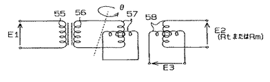
さらに、前記入力軸16aには、その外周上に第3ヨーク53が一体回転可能に固定されており、この第3ヨーク53の周囲には、第3コイル57が巻き回されている。この第3コイル57は前記第2コイル56に接続されている。そして、前記第3ヨーク53と対向するように、ピニオンハウジング17の内周には、第4ヨーク54が固定されており、同第4ヨーク54には第4コイル58が巻き回されている。第3コイル57および第4コイル58は、位相を90度ずらした2種類のコイルから構成されている。
【0032】
次に、第2レゾルバ24について説明する。なお、その詳細については上記した第1レゾルバ23とほぼ同様であるため、第1レゾルバ23のヨーク51〜54及びコイル55〜58と同一符号を用いる。そして、異なるところのみを説明する。
【0033】
第2レゾルバ24は、第1〜第4ヨーク51〜54と第1〜第4コイル55〜58とから構成されており、ピニオンハウジング17に設けられているが、第2、第3ヨーク52、53及び第2、第3コイル56、57は、出力軸16bに設けられている。その他の構成については、第1レゾルバ23と同様とされている。
【0034】
次に、第1レゾルバ23と第2レゾルバ24とハンドル1回転について、電気的特性を図7に基づいて説明する。本実施例では、第1レゾルバ23の出力θt1は(B)−(1)で示されるように、ハンドル1回転につき5つのピーク点を有している。これは電気的には5つのN極、S極を有しており、機械角360°に対して、電機角360°×5=1800°に当たる。これは電気角360°のレゾルバより5倍の分解能を有していることを意味している。
【0035】
また、第2レゾルバ24の出力θt2は(B)−(2)で示されるように、ハンドル1回転につき6つのピーク点を有している。これは電気的には6つのN極、S極を有しており、機械角360°に対して、電機角360°×6=2160°に当たる。これは電気角360°のレゾルバより6倍の分解能を有していることを意味している。
【0036】
(B)−(1)および(B)−(2)からわかるように、第1レゾルバ23の出力θt1と第2レゾルバ24の出力θt2は同じハンドル回転角において、同じ値を取る事はない。そのため、第1レゾルバ23の出力θt1と第2レゾルバ24の出力θt2を使用して、ハンドル1回転に高分解能の出力信号θtを生成することができる。
【0037】
次に、第1及び第2レゾルバ23、24に基づいたトルク検出について説明する。ハンドル18が操舵され、入力軸16aが回転角θ1で回転した場合に、図4に示すように、第1コイル55に交流電圧E1を加えると、その電圧に応じて第1ヨーク51及び第2ヨーク52に磁束が発生する。そして、そのときの磁束変化に応じて第2コイル56には交流電圧が誘起される。第2コイル56は第3コイル57に接続しているため、当該第3コイル57にも交流電圧が発生する。そして、当該第3コイル57に発生した交流電圧によって、第4コイル58には交流電圧が誘起されて、交流電圧E2,E3が出力される。このとき、2種類のコイルから構成された第4コイル58からは、位相の異なる2種類の交流電圧E2,E3が出力され、これらは次の式(a)及び式(b)の関係を満たす。
【0038】
E2=K・E1×cosθ…(a)
E3=K・E1×sinθ…(b)
なお、Kは変圧比を示す。このとき、上記式(a)及び式(b)からθを算出することができ、この角度θが入力軸16aの回転角θ1となる。
【0039】
一方、入力軸16aが回転すると、トーションバー20を介して連結された出力軸16bも回転する。そして、出力軸16b側に設けられた第2レゾルバ24から前記式(a)及び式(b)に基づいて、出力軸16bの回転角θ2も算出される。
【0040】
ここで、入力軸16aと出力軸16bの回転に際して、トーションバー20の捻れにより、入力軸16aと出力軸16bの間で相対回転角度差Δθ(=θ1−θ2)が生じる。その結果、このトーションバー20の捻れ角度である相対回転角度差Δθとトーションバー20の剛性とから操舵トルクは算出される。
【0041】
そして、この操舵トルクに応じて操舵力をアシストするための公知のアシスト制御が行なわれ、後述する電動モータ39によって、操舵力はアシストされ、好適にハンドル18の操舵が可能になる。
【0042】
図1及び図5に示すように、前記ラックハウジング12と第2ラックハウジング13とモータハウジング14とから構成された筒状体内には、回転不能かつ軸線方向に移動可能にラックシャフト27が内蔵されている。ラックシャフト27の両端部には図示しないタイロッドを介して左右の前輪が連結されている。そのラックシャフト27には、図2に示すように、ピニオンシャフト16のピニオンギア16cと噛合する噛み合い部27bが形成され、ラックアンドピニオン機構を形成している。
【0043】
図6に示すように、前記モータハウジング14の内周には巻線が施されたステータ29が嵌合され、ラックシャフト27の軸線方向の中間部には中空円筒状にモータシャフト28が同軸的にラックシャフト27の外側に遊嵌されている。
【0044】
モータシャフト28は、第1及び第2ベアリング30,31を介してモータハウジング14に支持されており、前記モータシャフト28には永久磁石37が外設して固定されている。
【0045】
モータシャフト28内にはボールネジナット36が同軸的に内嵌されており、同ボールネジナット36の内周面には螺旋状のボールネジ溝36aが設けられている。また、ラックシャフト27の外周面には軸線方向の所定範囲に螺旋状のボールネジ溝27aが設けられており、ボールネジ溝27aとボールネジ溝36aとの間には、図示しない多数のボールが転動可能に受容されている。そして、両ボールネジ溝27a、36a等から構成されるボールネジ機構により、モータシャフト28の正逆回転の回転トルクをラックシャフト27の軸線方向における往復動に変換する。その後、この往復動はラックアンドピニオン機構をなすピニオンシャフト16を介してハンドル18の操舵力を軽減するアシスト力となる。そして、上記したモータシャフト28、ステータ29等により、モータとしての電動モータ39が構成され、この電動モータ39は、前記ハンドル18の回転に応じて駆動される。
【0046】
モータシャフト28の外周側には、モータ回転角センサとしてのモータレゾルバ41が設けられている。モータレゾルバ41の詳細については、図3及び図4に示す第1レゾルバ23とほぼ同様であるため、第1レゾルバ23のヨーク51〜54及びコイル55〜58と同一符号を用いる。そして、異なるところのみを説明する。
【0047】
即ち、モータレゾルバ41は、第1〜第4ヨーク51〜54と第1〜第4コイル55〜58とから構成されており、第1、第4ヨーク51、54及び第1、第4コイル55、58は、モータハウジング14に設けられており、第2、第3ヨーク52,53及び第2、第3コイル56,57は、モータシャフト28に設けられている。その他の構成については、第1レゾルバ23と同様である。
【0048】
ここで、モータシャフト28の回転角(以下、モータ回転角という)の検出について説明する。モータシャフト28がある回転角で回転した場合に、第1コイル55に交流電圧E1を印加すると、その電圧に応じて第1ヨーク51に磁束が発生し、その磁束が第2ヨーク52に伝わる。その磁束が第2コイル56を鎖交することにより、交流電圧が誘起される。このとき、第2コイル56に誘起された交流電圧が接続された第3コイル57にも発生する。この第3コイル57に発生した交流電圧に基づいて、第4コイル58に交流電圧が誘起され、交流電圧E2、E3が出力される。そして、印加された交流電圧E1と出力された交流電圧E2,E3とから、前述した式(a)及び式(b)によりモータ回転角は算出される。このようにして検出されたモータ回転角は、電動パワーステアリング装置11における様々な制御に用いられる。
【0049】
次に、上記のように構成された電動パワーステアリング装置におけるハンドル18の絶対位置検出装置について説明する。図5に示すように、トルクセンサ22を構成した第1及び第2レゾルバ23、24と、モータ回転角を検出するモータレゾルバ41は演算手段としてのECU(電子制御装置)43に電気的に接続されている。そして、本実施形態では、前記第1及び第2レゾルバ23、24、モータレゾルバ41、及びECU43から絶対位置検出装置が構成されている。前記第1及び第2レゾルバ23、24からは、ピニオンシャフト16の出力軸16bの回転角に応じてリニア出力された検出信号θt1、θt2が、ECU43に入力されるようになっている。また、モータレゾルバ41からは、モータシャフト28の回転角に応じてリニア出力された検出信号θmがECU43に入力されるようになっている。前記各検出信号θt1,θt2,θmは、第1レゾルバ23、第2レゾルバ24及びモータレゾルバ41を構成する第4コイル58から出力される交流電圧(E2またはE3)に相当し、本実施形態では、各レゾルバ23、24、41の第4コイル58を構成する2つのコイルのうち共に交流電圧E2を出力するコイルからの出力を示す。なお、交流電圧E2を出力するコイルに換えて交流電圧E3を出力するコイルからの出力を用いてもよい。
【0050】
そして、ECU43は入力された検出信号θt1,θt2,θmに基づいて、ハンドル18の絶対位置を検出するようになっている。なお、本実施形態において、絶対位置とは、中立位置から何度離れているかを示すものであり、中立位置とは、車両が直進するように前輪が配置された際のハンドル18の位置である。
【0051】
次に、ECU43において、絶対位置検出を行なうための演算式について説明する。本実施例では、ハンドル18は±2.0回転(±720°)の範囲内で回転するものとして説明する。+は、中立位置から時計回り方向への回転を示し、−は中立位置から反時計回り方向への回転を示す。
【0052】
トルクセンサのレゾルバ出力における検出信号θtの周期TtはTt=1周期とされている。図7(A)に示すようにハンドル1回転で1周期出力される。また、図8(B)に示すように電動モータ39(モータシャフト28)の1回転に対するモータレゾルバ41からの検出信号θmの周期Tm1は、Tm1=7周期となるように構成されている。
【0053】
一方、ハンドル18が1回転する間におけるラックシャフト27の移動距離はSmmとしている。また、ラックシャフト27及びモータシャフト28におけるボールネジ機構27a、36aの1回転分のリードをLとすると、ラックシャフト27がSmm移動する間に、モータシャフト28はS/L回転することになり、図8(A)で示すように、本実施例では8.2回転することになる。従って、ハンドル18(ピニオンシャフト16)の1回転に対するモータレゾルバ41からの検出信号θmの周期Tm2は、図8(B)で示すように、Tm2=57.4(=Tm1×8.2=7×8.2)周期となる。
【0054】
本実施例をハンドル18、トルクセンサによる操舵角(θt)、モータレゾルバの出力(θm)から見てみると図9のようになる。ハンドルは左右に最大2回転する。(A)はトルクセンサによる操舵角θtを示し、ハンドル1回転につき1周期の出力となる。これが第1検出信号である。(B)はそのときのモータレゾルバの出力θmを示す。これが第2検出信号である。
【0055】
ここで具体的に、トルクセンサによる操舵角度をθt、モータ回転角による電気角θmとして、それぞれの絶対位置を式であらわしてみる。
まずトルクセンサによる絶対位置=θt+360・A 式(1)
ここでAは整数で−2、−1、0、1をとる。
モータ回転角による絶対位置=(θm+360・B)/57.4 式(2)
ここでBは理論的には、ハンドルと電動モータを連結する機械系のガタや電動モータおよびトルクセンサのレゾルバの電気角絶対精度誤差等がない場合には、整数値となり、−126〜125の値をとる。
式(1)と式(2)は等しいので、
θt+360・A=(θm+360・B)/57.4となる。
よってB=(57.4・(θt+360・A)−θm)/360 式(3)
とあらわされる。
【0056】
この式(1)、(3)を使用して具体的に絶対舵角の検出方法を図10のフローチャートに従って説明する。このフローチャートは、定期的な割り込みにより起動する。まず、S900において、トルクセンサによる操舵角θtを読み込む。これが第1の検出手段である。具体的な数値として、θt=39.5°とする。次に、S902に進み、モータ回転角θmを読み込む。これが第2の検出手段である。同じくθm=284°とする。
【0057】
次に、S904に進み、ハンドルの回転数N(始めに左回転)をAに代入する。具体的な数値としてN=2として、左2回転のためA=−2とする。
次に、S906に進み、ループを回すカウンターCTRを1にセットする。次に、S908に進み、θt=39.5°、θm=284°、A=−2を式(3)に代入して、モータ回転数Bを求める。これが第1の演算手段である。

次に、S910に進み、Bの値をメモリに記憶する。次に、S912に進み、Aの値を同じくメモリに記憶する。次に、S914に進み、Aの値を1インクリメントする。次に、S916に進み、CTRの値も1インクリメントする。次に、S918に進み、AがNより大きいか判定する。今回の場合はAが2より大きいか判定する。今回は大きくないためS908へ戻る。
【0058】
S908では、θt=39.5°、θm=284°、A=−1を式(3)に代入して、モータ回転数Bを求める。
【0059】
S908では、θt=39.5°、θm=284°、A=0を式(3)に代入して、モータ回転数Bを求める。
【0060】
S908では、θt=39.5°、θm=284°、A=1を式(3)に代入して、モータ回転数Bを求める。
【0061】
S920では、全てのBの値のうち誤差が最も小さい値であるBを選ぶ。今回はB=62.909が該当する。これが第1の選択手段である。そしてその時のAの値を求める。今回はB=62.909としたAはA=1である。これが第2の選択手段である。次に、S922に進み、θt、Aの値を式(1)に代入し、絶対位置を求める。今回はθt=39.5°、A=1を代入する。
【0062】
課題で記述した、トルクセンサのレゾルバの舵角精度誤差や、ハンドルと電動モータを連結するギアのガタ、及び電動モータのレゾルバの電気角絶対精度誤差等は上記演算の中で小数点以下に含まれて記述されている。具体的には誤差ErはEr=63−62.909=0.091である。
【0063】
上記したような方法で、ハンドル18の絶対位置θを検出することができる。これにより、公知の電動パワーアシスト制御、ハンドル戻り制御等を好適に行なうことができる。従って、上記実施形態によれば、以下のような効果を得ることができる。
【0064】
【発明の効果】
(1)上記実施形態では、ハンドル18の回転により発生する操舵トルクを検出するためのトルクセンサ22の第1レゾルバ23と第2レゾルバ24及びハンドル18の回転に応じて駆動される電動モータ39のモータ回転角を検出するためのモータレゾルバ41と各レゾルバ23、24、41から出力される検出信号を演算処理するECU43とで、絶対位置検出装置を構成した。そしてECU43では、各レゾルバ23、24,41から出力される検出信号を使用してモータ回転角を演算し、まず演算した全てのモータ回転角のうち整数値に一番近いモータ回転角を選択し、次に、そのモータ回転角を与えたステアリングホイールの回転数を選択して、選択したステアリングホイールの回転数と第1検出信号とにより、絶対舵角θを検出した。従って、絶対舵角θを検出するために、必要である第1レゾルバ23と第2レゾルバ24とモータレゾルバ41は、操舵トルクを検出するための第1レゾルバ23と第2レゾルバ24とモータ回転角を検出するためのモータレゾルバ41を絶対位置検出装置として兼用しているため、従来と異なり、別途回転角センサを設ける必要がなく、コストの低減を図ることができ、好適に絶対舵角θを検出できる。
【0065】
(2)上記実施形態では、トルクセンサ22の第1レゾルバ23と第2レゾルバ24とモータレゾルバ41の両方を利用して、絶対位置検出装置を構成した。例えば、モータレゾルバ41のみを使用して、ハンドル18の絶対位置検出を行なうことを想定すると、ECU43はこの検出信号だけではロータたるモータシャフト28が検出信号にて形成される波形の一周期以内でどの位置にあるかしか判断できない。このため、ハンドル18の絶対位置θを特定することは困難である。また、トルクセンサ22の第2レゾルバ24からの検出信号のみを用いて、ハンドル18の回転角の検出は可能であるが、ECU43は、中立位置の特定、及び検出信号の波形の山が中立位置から何番目のものであるかは、判定できない。
【0066】
これに対して、トルクセンサ22の第1レゾルバ23と第2レゾルバ24とモータレゾルバ41の両方を用いて、ハンドル18の絶対位置検出を行なった本実施形態においては、トルクセンサのレゾルバの舵角精度誤差やハンドルと電動モータを連結するギアのガタ及び電動モータのレゾルバの電気角絶対精度誤差等があっても正確な電動パワーステアリング装置の絶対位置検出装置及び絶対位置検出方法を提供することができる。
【図面の簡単な説明】
【図1】電動パワーステアリング装置の構成図を示す。
【図2】トルクセンサを備えた部位を示す。
【図3】第1レゾルバを示す。
【図4】第1レゾルバの巻き線図を示す。
【図5】絶対位置検出装置の電気的構成を示すブロック図
【図6】電動パワーステアリング装置における電動モータを備えた部位を示す。
【図7】トルクセンサのレゾルバの出力波形を示す。
【図8】ハンドル1回転とモータレゾルバの出力波形を示す。
【図9】トルクセンサによる操舵角とモータレゾルバの出力
【図10】絶対位置演算のフローチャートを示す。
【符号の説明】
11:電動パワーステアリング装置
16:ピニオンシャフト
16a:入力軸
16b:出力軸
18:ステアリングホイール
20:トーションバー
23:第1レゾルバ(第1の検出手段)
24:第2レゾルバ(第1の検出手段)
39:電動モータ
41:モータレゾルバ(第2の検出手段)
43:ECU(演算手段)[0001]
BACKGROUND OF THE INVENTION
The present invention relates to an absolute position detection device and an absolute position detection method for a multi-rotor that performs multiple rotations of one or more rotations, particularly an electric power steering device for detecting the absolute position of a steering wheel.
[0002]
[Prior art]
2. Description of the Related Art Conventionally, there has been known an electric power steering device that applies an assist force by an electric motor to a steering system in order to reduce a steering force of a steering wheel (hereinafter referred to as a steering wheel). In various controls in this electric power steering apparatus, the absolute position of the handle that rotates within a finite number of rotations of one rotation or more (a position indicating how many times it is from the neutral position) is used. The neutral position is the position of the steering wheel when the tire is steered so that the vehicle goes straight.
[0003]
A rotation angle sensor is generally known as a sensor for detecting the absolute position of the handle. This rotation angle sensor is composed of a slit plate having a large number of slits provided so as to rotate integrally with the handle, and three sets of photo interrupters provided in a fixed state on the steering column.
[0004]
Of the three sets of photointerrupters, two sets of photointerrupters are for detecting the amount of rotation and the direction of rotation of the slit plate, and the remaining one set of photointerrupters sets the neutral position during one rotation of the handle. It is for detection. These output signals are used for vehicle control.
[0005]
The range in which the handle can be rotated is generally not within one rotation (360 degrees), but is, for example, ± 720 two rotations (720 degrees) in the left direction and two rotations (720 degrees) in the right direction around the neutral position. It is a degree. However, of the output signals from the rotation angle sensor described above, even if there is an output from the set of photo interrupters for detecting the neutral position, it is unclear how many rotations it is. For this reason, the exact absolute position of the handle cannot be detected only by the output signal from the rotation angle sensor. Therefore, various means for detecting an absolute position using an output signal from a rotation angle sensor are used.
[0006]
Recently, however, cost reduction has been demanded in detecting the absolute position of the handle. However, conventionally, for the purpose of detecting the absolute position of the handle, there has been a problem that a rotation angle sensor having a complicated configuration as described above must be provided with a device for detecting how many turns the handle is.
[0007]
Incidentally, the electric motor of the electric power steering apparatus is provided with a resolver as a device for detecting the position of the motor, and a torque sensor as a device for detecting steering torque of the steering wheel. Since these all output a rotation angle signal, it is conceivable to use this signal for cost reduction. However, even when trying to detect the absolute angle using the resolver signal of the electric motor, it is difficult to determine the absolute position of the handle because it knows only where the resolver rotor is within one electrical angle cycle. It was.
[0008]
The resolver of the torque sensor detects torsion of a torsion bar provided between an input shaft connected to the handle and an output shaft. However, since the resolver of the torque sensor also outputs a plurality of signals per one rotation of the handle, it is difficult to specify the absolute position of the handle. Therefore, the absolute position of the steering wheel cannot be detected even if the signals output from the resolver of the electric motor and the torque sensor are used alone.
[0009]
Therefore, for example, there is a method for detecting the absolute position of the handle described in Japanese Patent Application No. 2001-268388 (hereinafter referred to as a conventional example). According to the absolute position detection method of the steering wheel, the first detection signal for detecting the steering torque of the steering wheel outputs a first detection signal linearly according to the rotation angle of the steering wheel. Further, the second detection signal that is driven in accordance with the rotation of the handle and detects the rotation of the motor that assists the rotation of the handle detects a second detection signal having a period different from that of the first detection unit. Is output. Then, the absolute position of the handle is calculated based on the deviation between the first and second detection signals and the reference deviation between the two detection signals per rotation of the handle by the calculation means.
[0010]
[Problems to be solved by the invention]
However, in the above conventional example, the steering angle accuracy error of the resolver of the torque sensor, the play of the gear connecting the handle and the electric motor, and the absolute accuracy error of the electric angle of the resolver of the electric motor are not considered. Therefore, there has been an unsolved problem that the exact absolute position of the handle cannot be detected.
[0011]
Therefore, the present invention has been made paying attention to the above-mentioned unsolved problems of the conventional example, the rudder angle accuracy error of the resolver of the torque sensor, the backlash of the gear connecting the handle and the electric motor, and the resolver of the electric motor. An object of the present invention is to provide an absolute position detection device and an absolute position detection method for an electric power steering apparatus that can accurately detect an absolute position even if there is an electrical angle absolute accuracy error or the like.
[0012]
[Means for Solving the Problems]
In order to achieve the above object, an absolute position detection device for an electric power steering apparatus according to
[0013]
Further, in order to achieve the above object, in the absolute position detection device for an electric power steering apparatus according to
[0014]
In order to achieve the above object, in the absolute position detection device for an electric power steering apparatus according to claim 3, the first detection means does not take the same value during one rotation of the steering wheel. A technical feature is that it is composed of more than one resolver.
[0015]
In order to achieve the above object, the absolute position detection device for an electric power steering apparatus according to claim 4 is characterized in that the first selection means selects a numerical value closest to an integer value. .
[0016]
Further, in order to achieve the above object, in the absolute position detection device for an electric power steering apparatus according to claim 5, the second calculation means sets 360 to the rotation speed of the steering wheel selected by the second selection means. A technical feature is that an absolute position is detected by an adding means for adding the first detection signal to a value multiplied by.
[0017]
In order to achieve the above object, in the absolute position detection method for an electric power steering apparatus according to claim 6, a steering wheel, a motor for assisting rotation of the steering wheel, and a steering torque of the steering wheel are detected. A first detection step for torque detection that linearly outputs a first detection signal according to the rotation angle of the steering wheel, and driven according to the rotation of the steering wheel to rotate the steering wheel. A second detection step of detecting rotation of the assisting motor and linearly outputting a second detection signal having a period different from that of the first detection signal;
Based on the first and second detection signals and the rotation speed of the steering wheel, a first calculation step for calculating the rotation speed of the motor and an appropriate rotation speed among the rotation speeds of the motor obtained by the first calculation step A first selection step of selecting a proper rotation number, a second selection step of selecting a rotation number of the steering wheel corresponding to the appropriate rotation number obtained by the first selection step, and the second And a second calculation step for calculating an absolute position based on the number of rotations of the steering wheel obtained by the selection step and the first detection signal.
[0018]
[Action]
According to the first aspect of the invention, the first detection signal for detecting the steering torque of the steering wheel linearly outputs the first detection signal according to the rotation of the steering wheel. A second detection signal having a period different from that of the first detection signal is detected by a second detection means that detects the rotation of a motor that is driven according to the rotation of the steering wheel and assists the rotation of the steering wheel. Linear output. Then, the rotational speed of the motor is calculated for all the possibilities of the first and second detection signals and the rotational speed of the steering wheel. Then, an appropriate rotation speed is selected from the calculated rotation speeds of the motor, and the rotation speed of the steering wheel corresponding to the appropriate rotation speed is selected. Then, the absolute position is calculated based on the rotation speed of the steering wheel and the first detection signal.
[0019]
According to the invention of
[0020]
According to the invention of claim 3, the first resolver is used for the first rotating shaft connected to the steering wheel, and the rotation angle of the second rotating shaft connected to the first rotating shaft via the torsion bar is detected. Since the first resolver and the second resolver do not take the same value while the steering wheel rotates once, the output from the calculation results of the first and second resolvers is used. The absolute position detection during one rotation of the steering wheel is realized based on the first detection signal.
[0021]
According to the fourth aspect of the present invention, all the rotational speeds of the motor driven in accordance with the rotation of the steering wheel and assisting the rotation of the steering wheel are detected, and the rotational speed closest to the integer value among them is detected. Therefore, the correct rotation speed of the steering wheel can be selected.
[0022]
According to the fifth aspect of the invention, the absolute position of the steering wheel can be detected by adding the first detection signal to a value obtained by multiplying the correct steering wheel speed by 360.
[0023]
According to the sixth aspect of the present invention, the first detection signal for detecting the steering torque of the steering wheel linearly outputs the first detection signal in accordance with the rotation of the steering wheel. Further, a second detection signal having a period different from the first detection signal is detected by a second detection step that detects the rotation of the motor that is driven according to the rotation of the steering wheel and assists the rotation of the steering wheel. Linear output. Then, the rotational speed of the motor is calculated for all the possibilities of the first and second detection signals and the rotational speed of the steering wheel. Then, an appropriate rotation speed is selected from the calculated rotation speeds of the motor, and the rotation speed of the steering wheel corresponding to the appropriate rotation speed is selected. Then, the absolute position is calculated based on the rotation speed of the steering wheel and the first detection signal.
[0024]
DETAILED DESCRIPTION OF THE INVENTION
1 to 10 show an embodiment of an absolute position detection apparatus and an absolute position detection method for detecting an absolute rotation angle (hereinafter referred to as an absolute position) of a handle in an electric power steering apparatus. explain.
[0025]
FIG. 1 shows an electric
[0026]
A
[0027]
As shown in FIG. 2, the
[0028]
A
[0029]
A
[0030]
As shown in FIG. 3, the
[0031]
Further, a
[0032]
Next, the
[0033]
The
[0034]
Next, electrical characteristics of the
[0035]
Further, the output θt2 of the
[0036]
As can be seen from (B)-(1) and (B)-(2), the output θt1 of the
[0037]
Next, torque detection based on the first and
[0038]
E2 = K · E1 × cos θ (a)
E3 = K · E1 × sinθ (b)
Note that K represents a transformation ratio. At this time, θ can be calculated from the above equations (a) and (b), and this angle θ becomes the rotation angle θ1 of the
[0039]
On the other hand, when the
[0040]
Here, when the
[0041]
Then, known assist control for assisting the steering force is performed in accordance with the steering torque, and the steering force is assisted by an
[0042]
As shown in FIGS. 1 and 5, a
[0043]
As shown in FIG. 6, a
[0044]
The
[0045]
A
[0046]
A
[0047]
That is, the
[0048]
Here, detection of the rotation angle of the motor shaft 28 (hereinafter referred to as the motor rotation angle) will be described. When the
[0049]
Next, an absolute position detection device for the
[0050]
The
[0051]
Next, an arithmetic expression for performing absolute position detection in the
[0052]
The period Tt of the detection signal θt in the resolver output of the torque sensor is Tt = 1 period. As shown in FIG. 7A, one cycle of output is performed with one rotation of the handle. Further, as shown in FIG. 8B, the period Tm1 of the detection signal θm from the
[0053]
On the other hand, the movement distance of the
[0054]
When the present embodiment is viewed from the
[0055]
Specifically, the absolute position of each is expressed by an equation, where the steering angle by the torque sensor is θt and the electrical angle θm by the motor rotation angle.
First, absolute position by torque sensor = θt + 360 · A Formula (1)
Here, A is an integer and takes -2, -1, 0, 1.
Absolute position by motor rotation angle = (θm + 360 · B) /57.4 Formula (2)
Here, B is theoretically an integer value when there is no electrical backlash of the mechanical system connecting the handle and the electric motor, or the electrical angle absolute accuracy error of the resolver of the electric motor and torque sensor. Takes a value.
Since equation (1) and equation (2) are equal,
θt + 360 · A = (θm + 360 · B) /57.4.
Therefore, B = (57.4 · (θt + 360 · A) −θm) / 360 Equation (3)
It is expressed.
[0056]
A method for detecting the absolute steering angle will be specifically described with reference to the flowchart of FIG. 10 using the equations (1) and (3). This flowchart is activated by a periodic interrupt. First, in S900, the steering angle θt by the torque sensor is read. This is the first detection means. As a specific numerical value, θt = 39.5 °. In step S902, the motor rotation angle θm is read. This is the second detection means. Similarly, θm = 284 °.
[0057]
Next, proceeding to S904, the rotation speed N (first left rotation) of the handle is substituted into A. As a specific numerical value, N = 2, and A = -2 for two rotations to the left.
In step S906, a counter CTR for turning the loop is set to 1. In step S908, θt = 39.5 °, θm = 284 °, and A = −2 are substituted into equation (3) to obtain the motor rotation speed B. This is the first calculation means.
Next, in S910, the value B is stored in the memory. In step S912, the value A is stored in the memory. In step S914, the value A is incremented by 1. In step S916, the value of CTR is also incremented by one. Next, in S918, it is determined whether A is greater than N. In this case, it is determined whether A is larger than 2. Since it is not large this time, it returns to S908.
[0058]
In S908, θt = 39.5 °, θm = 284 °, and A = −1 are substituted into Equation (3) to obtain the motor rotation speed B.
[0059]
In S908, θt = 39.5 °, θm = 284 °, and A = 0 are substituted into equation (3) to determine the motor rotation speed B.
[0060]
In S908, θt = 39.5 °, θm = 284 °, and A = 1 are substituted into equation (3) to determine the motor rotation speed B.
[0061]
In S920, B that has the smallest error among all B values is selected. This time, B = 62.909 is applicable. This is the first selection means. Then, the value of A at that time is obtained. In this case, B = 62.909, A is A = 1. This is the second selection means. Next, proceeding to S922, the values of θt and A are substituted into equation (1) to obtain the absolute position. In this case, θt = 39.5 ° and A = 1 are substituted.
[0062]
The steering angle accuracy error of the resolver of the torque sensor, the gear play of the gear connecting the handle and the electric motor, and the absolute accuracy error of the electric angle of the resolver of the electric motor described in the problem are included in the above decimal point in the above calculation. Is described. Specifically, the error Er is Er = 63−62.909 = 0.091.
[0063]
The absolute position θ of the
[0064]
【The invention's effect】
(1) In the above embodiment, the
[0065]
(2) In the above embodiment, the absolute position detection device is configured by using both the
[0066]
On the other hand, in the present embodiment in which the absolute position of the
[Brief description of the drawings]
FIG. 1 shows a configuration diagram of an electric power steering apparatus.
FIG. 2 shows a part provided with a torque sensor.
FIG. 3 shows a first resolver.
FIG. 4 shows a winding diagram of a first resolver.
FIG. 5 is a block diagram showing an electrical configuration of the absolute position detection device.
FIG. 6 shows a portion provided with an electric motor in the electric power steering apparatus.
FIG. 7 shows an output waveform of a resolver of a torque sensor.
FIG. 8 shows the output waveform of one rotation of the handle and the motor resolver.
FIG. 9: Steering angle and output of motor resolver by torque sensor
FIG. 10 shows a flowchart of absolute position calculation.
[Explanation of symbols]
11: Electric power steering device
16: Pinion shaft
16a: input shaft
16b: Output shaft
18: Steering wheel
20: Torsion bar
23: First resolver (first detection means)
24: Second resolver (first detection means)
39: Electric motor
41: Motor resolver (second detection means)
43: ECU (calculation means)
Claims (6)
前記ステアリングホイールの回転をアシストするモータと、
前記ステアリングホイールの操舵トルクを検出するために設けられ、前記ステアリングホイールの回転角に応じて第1検出信号をリニア出力するトルク検出用の第1の検出手段と、
前記ステアリングホイールの回転に応じて駆動されて、同ステアリングホイールの回転をアシストするモータの回転を検出し、前記第1検出信号とは異なる周期を有する第2検出信号をリニア出力する第2の検出手段と、
前記第1及び第2検出信号と前記ステアリングホイールの回転数より、前記モータの回転数を演算する第1の演算手段と、
前記第1の演算手段により求められた前記モータの回転数のうち適切な回転数を選択する第1の選択手段と、
前記第1の選択手段により求められた前記適切な回転数に対応する前記ステアリングホイールの回転数を選択する第2の選択手段と、
前記第2の選択手段により求められた前記ステアリングホイールの回転数と前記第1検出信号により絶対位置を演算する第2の演算手段と、
を備えたことを特徴とする電動パワーステアリング装置の絶対位置検出装置。A steering wheel,
A motor for assisting rotation of the steering wheel;
First detection means for torque detection, which is provided for detecting a steering torque of the steering wheel and linearly outputs a first detection signal in accordance with a rotation angle of the steering wheel;
A second detection that is driven according to the rotation of the steering wheel, detects the rotation of a motor that assists the rotation of the steering wheel, and linearly outputs a second detection signal having a period different from the first detection signal. Means,
A first computing means for computing the rotational speed of the motor from the first and second detection signals and the rotational speed of the steering wheel;
First selection means for selecting an appropriate rotational speed among the rotational speeds of the motor obtained by the first computing means;
Second selection means for selecting a rotation speed of the steering wheel corresponding to the appropriate rotation speed determined by the first selection means;
Second computing means for computing an absolute position based on the number of rotations of the steering wheel determined by the second selecting means and the first detection signal;
An absolute position detecting device for an electric power steering device.
前記ステアリングホイールの回転をアシストするモータと、
前記ステアリングホイールの操舵トルクを検出するために設けられ、前記ステアリングホイールの回転角に応じて第1検出信号をリニア出力するトルク検出用の第1の検出ステップと、
前記ステアリングホイールの回転に応じて駆動されて、同ステアリングホイールの回転をアシストするモータの回転を検出し、前記第1検出信号とは異なる周期を有する第2検出信号をリニア出力する第2の検出ステップと、
前記第1及び第2検出信号と前記ステアリングホイールの回転数より、前記モータの回転数を演算する第1の演算ステップと、
前記第1の演算ステップにより求められた前記モータの回転数のうち適切な回転数を選択する第1の選択ステップと、
前記第1の選択ステップにより求められた前記適切な回転数に対応する前記ステアリングホイールの回転数を選択する第2の選択ステップと、
前記第2の選択ステップにより求められた前記ステアリングホイールの回転数と前記第1検出信号により絶対位置を演算する第2の演算ステップと、
を備えたことを特徴とする電動パワーステアリング装置の絶対位置検出方法。A steering wheel,
A motor for assisting rotation of the steering wheel;
A first detection step for torque detection, which is provided for detecting a steering torque of the steering wheel and linearly outputs a first detection signal in accordance with a rotation angle of the steering wheel;
A second detection that is driven according to the rotation of the steering wheel, detects the rotation of a motor that assists the rotation of the steering wheel, and linearly outputs a second detection signal having a period different from the first detection signal. Steps,
A first calculation step of calculating the rotation speed of the motor from the first and second detection signals and the rotation speed of the steering wheel;
A first selection step of selecting an appropriate rotational speed among the rotational speeds of the motor obtained in the first calculation step;
A second selection step of selecting a rotation speed of the steering wheel corresponding to the appropriate rotation speed determined by the first selection step;
A second calculation step of calculating an absolute position based on the number of rotations of the steering wheel determined in the second selection step and the first detection signal;
An absolute position detection method for an electric power steering apparatus, comprising:
Priority Applications (5)
| Application Number | Priority Date | Filing Date | Title |
|---|---|---|---|
| JP2002196131A JP3969220B2 (en) | 2002-07-04 | 2002-07-04 | Absolute position detection device and absolute position detection method for electric power steering device |
| EP03741193A EP1550839B1 (en) | 2002-07-04 | 2003-07-04 | Absolute steering angle detection device and absolute steering angle detection method for electric power steering device |
| DE60334009T DE60334009D1 (en) | 2002-07-04 | 2003-07-04 | DEVICE AND METHOD FOR DETECTING THE ABSOLUTE CONTROL ANGLE FOR AN ELECTRIC SERVO CONTROL UNIT |
| US10/515,336 US7149615B2 (en) | 2002-07-04 | 2003-07-04 | Absolute steering angle detection device and absolute steering angle detection method for electric power steering device |
| PCT/JP2003/008511 WO2004005843A1 (en) | 2002-07-04 | 2003-07-04 | Absolute steering angle detection device and absolute steering angle detection method for electric power steering device |
Applications Claiming Priority (1)
| Application Number | Priority Date | Filing Date | Title |
|---|---|---|---|
| JP2002196131A JP3969220B2 (en) | 2002-07-04 | 2002-07-04 | Absolute position detection device and absolute position detection method for electric power steering device |
Publications (2)
| Publication Number | Publication Date |
|---|---|
| JP2004037312A JP2004037312A (en) | 2004-02-05 |
| JP3969220B2 true JP3969220B2 (en) | 2007-09-05 |
Family
ID=30112359
Family Applications (1)
| Application Number | Title | Priority Date | Filing Date |
|---|---|---|---|
| JP2002196131A Expired - Fee Related JP3969220B2 (en) | 2002-07-04 | 2002-07-04 | Absolute position detection device and absolute position detection method for electric power steering device |
Country Status (5)
| Country | Link |
|---|---|
| US (1) | US7149615B2 (en) |
| EP (1) | EP1550839B1 (en) |
| JP (1) | JP3969220B2 (en) |
| DE (1) | DE60334009D1 (en) |
| WO (1) | WO2004005843A1 (en) |
Families Citing this family (22)
| Publication number | Priority date | Publication date | Assignee | Title |
|---|---|---|---|---|
| JP3969220B2 (en) * | 2002-07-04 | 2007-09-05 | 株式会社ジェイテクト | Absolute position detection device and absolute position detection method for electric power steering device |
| JP3842235B2 (en) | 2003-03-27 | 2006-11-08 | 株式会社ジェイテクト | Control parameter setting method, control parameter setting device, and electric power steering device |
| JP2005091204A (en) | 2003-09-18 | 2005-04-07 | Toyoda Mach Works Ltd | Electric power steering device |
| JP4604551B2 (en) * | 2003-09-24 | 2011-01-05 | 株式会社ジェイテクト | Resolver signal arithmetic processing method and arithmetic processing apparatus |
| JP2005219573A (en) * | 2004-02-04 | 2005-08-18 | Denso Corp | Electric power steering control device of vehicle |
| JP4600653B2 (en) | 2004-10-28 | 2010-12-15 | 株式会社ジェイテクト | Steering control device |
| US7295907B2 (en) * | 2005-06-14 | 2007-11-13 | Trw Automotive U.S. Llc | Recovery of calibrated center steering position after loss of battery power |
| RU2278797C1 (en) * | 2005-08-19 | 2006-06-27 | Открытое акционерное общество "Калужский завод электронных изделий" | Electromechanical steering booster and steering booster electric motor |
| JP2007253703A (en) * | 2006-03-22 | 2007-10-04 | Jtekt Corp | Electric power steering system |
| US7834576B2 (en) * | 2007-05-14 | 2010-11-16 | Gm Global Technology Operations, Inc. | Apparatus and methods for diagnosing motor-resolver system faults |
| EP1992549B1 (en) * | 2007-05-18 | 2012-07-25 | GM Global Technology Operations LLC | Method for determining an absolute rotational position of a Vehicle Steering Column |
| JP4329859B2 (en) * | 2007-12-12 | 2009-09-09 | トヨタ自動車株式会社 | Steering control device |
| FR2933364B1 (en) * | 2008-07-07 | 2010-07-30 | Jtekt Europe Sas | ELECTRIC POWER STEERING SYSTEM OF A MOTOR VEHICLE |
| JP2010048760A (en) * | 2008-08-25 | 2010-03-04 | Jtekt Corp | Anomaly detection unit for resolver and electric power steering apparatus |
| JP5267031B2 (en) * | 2008-10-09 | 2013-08-21 | 株式会社ジェイテクト | Electric power steering device |
| US8428822B2 (en) | 2009-03-13 | 2013-04-23 | Honda Motor Co., Ltd. | Method of determining a steering angle in a motor vehicle |
| JP5369869B2 (en) * | 2009-04-24 | 2013-12-18 | 株式会社ジェイテクト | Electric power steering device |
| EP2448805B1 (en) * | 2009-06-29 | 2015-01-07 | Volvo Lastvagnar AB | A method and a system for assisting a driver of a vehicle during operation |
| JP5616281B2 (en) * | 2011-04-15 | 2014-10-29 | 日立オートモティブシステムズステアリング株式会社 | Torque sensor and power steering device |
| US10328972B2 (en) * | 2016-04-06 | 2019-06-25 | Denso Corporation | Rotation detecting apparatus and electric power steering apparatus using the same |
| WO2018038108A1 (en) * | 2016-08-26 | 2018-03-01 | 日本精工株式会社 | Control device for electric power steering device |
| CN111186490B (en) * | 2019-01-28 | 2021-08-27 | 上海衡鲁汽车科技有限公司 | Steering wheel corner estimation method and system based on Ackerman steering theorem |
Family Cites Families (24)
| Publication number | Priority date | Publication date | Assignee | Title |
|---|---|---|---|---|
| JPS59186713A (en) * | 1983-03-18 | 1984-10-23 | Mazda Motor Corp | Suspension for automobile |
| JPS6018455A (en) * | 1983-07-09 | 1985-01-30 | Jidosha Kiki Co Ltd | Control method for power steering device |
| DE3664604D1 (en) * | 1985-03-27 | 1989-08-31 | Toyoda Machine Works Ltd | Driving status discrimination device for a motor vehicle |
| JPH059515Y2 (en) * | 1986-06-11 | 1993-03-09 | ||
| JP2515891B2 (en) * | 1989-09-20 | 1996-07-10 | 株式会社日立製作所 | Angle sensor, torque sensor, and electric power steering device controlled according to the outputs of the sensors |
| JP2524246B2 (en) * | 1990-06-13 | 1996-08-14 | 本田技研工業株式会社 | Drive wheel slip control device |
| US5353004A (en) * | 1990-10-31 | 1994-10-04 | Aisin Seiki Kabushiki Kaisha | Sensor for detecting steering angle |
| JPH04176779A (en) * | 1990-11-08 | 1992-06-24 | Toyota Motor Corp | Electric control device for four-wheel steering vehicle |
| JPH04189677A (en) * | 1990-11-21 | 1992-07-08 | Toyota Motor Corp | Rear wheel steering device for four-wheel steering vehicle |
| US5437583A (en) * | 1993-04-16 | 1995-08-01 | Honda Giken Kogyo Kabushiki Kaisha | Torque distributing mechanism for differential |
| JP3509331B2 (en) * | 1995-10-11 | 2004-03-22 | 本田技研工業株式会社 | Vehicle wheel pressure reduction judgment device |
| US5794164A (en) * | 1995-11-29 | 1998-08-11 | Microsoft Corporation | Vehicle computer system |
| JP2852640B2 (en) * | 1996-04-12 | 1999-02-03 | 光洋精工株式会社 | Electric power steering device |
| JP3257971B2 (en) * | 1997-09-12 | 2002-02-18 | 本田技研工業株式会社 | Electric power steering device |
| GB9902438D0 (en) | 1999-02-05 | 1999-03-24 | Trw Lucas Varity Electric | Improvements relating to electric power assisted steering assemblies |
| US6411867B1 (en) * | 1999-10-27 | 2002-06-25 | Fujitsu Ten Limited | Vehicle driving support system, and steering angle detection device |
| JP2001194251A (en) | 2000-01-06 | 2001-07-19 | Tamagawa Seiki Co Ltd | Power steering detector |
| JP2001341658A (en) * | 2000-03-29 | 2001-12-11 | Toyoda Mach Works Ltd | Controller for electric power steering device |
| JP2002081961A (en) | 2000-09-07 | 2002-03-22 | Koyo Seiko Co Ltd | Rotary angle detector, brushless motor and motor operated power steering system |
| JP2002090109A (en) * | 2000-09-20 | 2002-03-27 | Koyo Seiko Co Ltd | Rotating angle detector, torque detector and steering device |
| JP3789791B2 (en) | 2001-09-05 | 2006-06-28 | 株式会社ジェイテクト | Absolute position detection apparatus and absolute position detection method |
| JP3969220B2 (en) * | 2002-07-04 | 2007-09-05 | 株式会社ジェイテクト | Absolute position detection device and absolute position detection method for electric power steering device |
| JP4042049B2 (en) * | 2003-04-16 | 2008-02-06 | 株式会社ジェイテクト | Steering angle detection device for electric power steering device |
| JP4619819B2 (en) * | 2005-02-24 | 2011-01-26 | 本田技研工業株式会社 | Power steering system for rough terrain vehicle |
-
2002
- 2002-07-04 JP JP2002196131A patent/JP3969220B2/en not_active Expired - Fee Related
-
2003
- 2003-07-04 EP EP03741193A patent/EP1550839B1/en not_active Expired - Lifetime
- 2003-07-04 US US10/515,336 patent/US7149615B2/en not_active Expired - Lifetime
- 2003-07-04 WO PCT/JP2003/008511 patent/WO2004005843A1/en active Application Filing
- 2003-07-04 DE DE60334009T patent/DE60334009D1/en not_active Expired - Lifetime
Also Published As
| Publication number | Publication date |
|---|---|
| EP1550839A1 (en) | 2005-07-06 |
| EP1550839B1 (en) | 2010-09-01 |
| US7149615B2 (en) | 2006-12-12 |
| US20050236221A1 (en) | 2005-10-27 |
| EP1550839A4 (en) | 2007-04-25 |
| DE60334009D1 (en) | 2010-10-14 |
| WO2004005843A1 (en) | 2004-01-15 |
| JP2004037312A (en) | 2004-02-05 |
Similar Documents
| Publication | Publication Date | Title |
|---|---|---|
| JP3969220B2 (en) | Absolute position detection device and absolute position detection method for electric power steering device | |
| JP3789791B2 (en) | Absolute position detection apparatus and absolute position detection method | |
| JP5616281B2 (en) | Torque sensor and power steering device | |
| EP3423333B1 (en) | Ripple minimization by proper as/ts magnet arrangement in electric power assisted steering apparatus | |
| JP4042049B2 (en) | Steering angle detection device for electric power steering device | |
| JP2005091137A (en) | Rudder angle sensor | |
| JP2017015696A (en) | Relative angle detection device, torque sensor, electrically-driven power steering device and vehicle | |
| US9625249B2 (en) | Rotation angle detection device and electric power steering system including the same | |
| JP6108009B2 (en) | Relative angle detection device, torque sensor, electric power steering device, and vehicle | |
| JP2004291807A (en) | Method and device for setting control parameter, and electric power steering device | |
| JP2009292331A (en) | Steering device for vehicle | |
| US6935194B2 (en) | Dual resolver device | |
| JP4020013B2 (en) | Vehicle steering system | |
| JP2007263693A (en) | Steering angle detector | |
| JP2012141276A (en) | Rotation angle detecting device | |
| JP5712724B2 (en) | Torque detection device and electric power steering device | |
| JP4238702B2 (en) | Absolute steering position detector | |
| WO2022102350A1 (en) | Rotation angle detection device | |
| JP2005098781A (en) | Failure detection method and device of torque sensor | |
| CN118794325A (en) | Position detecting device | |
| JP2007155641A (en) | Resolver device and torque sensor using the same | |
| JP2007278924A (en) | Turning angle detector | |
| JP2014162248A (en) | Electric power steering device | |
| JP2006297974A (en) | Electric power steering device |
Legal Events
| Date | Code | Title | Description |
|---|---|---|---|
| A621 | Written request for application examination |
Free format text: JAPANESE INTERMEDIATE CODE: A621 Effective date: 20050318 |
|
| A711 | Notification of change in applicant |
Free format text: JAPANESE INTERMEDIATE CODE: A712 Effective date: 20060228 |
|
| TRDD | Decision of grant or rejection written | ||
| A01 | Written decision to grant a patent or to grant a registration (utility model) |
Free format text: JAPANESE INTERMEDIATE CODE: A01 Effective date: 20070515 |
|
| A61 | First payment of annual fees (during grant procedure) |
Free format text: JAPANESE INTERMEDIATE CODE: A61 Effective date: 20070528 |
|
| R150 | Certificate of patent or registration of utility model |
Free format text: JAPANESE INTERMEDIATE CODE: R150 Ref document number: 3969220 Country of ref document: JP Free format text: JAPANESE INTERMEDIATE CODE: R150 |
|
| FPAY | Renewal fee payment (event date is renewal date of database) |
Free format text: PAYMENT UNTIL: 20100615 Year of fee payment: 3 |
|
| FPAY | Renewal fee payment (event date is renewal date of database) |
Free format text: PAYMENT UNTIL: 20110615 Year of fee payment: 4 |
|
| FPAY | Renewal fee payment (event date is renewal date of database) |
Free format text: PAYMENT UNTIL: 20120615 Year of fee payment: 5 |
|
| FPAY | Renewal fee payment (event date is renewal date of database) |
Free format text: PAYMENT UNTIL: 20120615 Year of fee payment: 5 |
|
| FPAY | Renewal fee payment (event date is renewal date of database) |
Free format text: PAYMENT UNTIL: 20130615 Year of fee payment: 6 |
|
| LAPS | Cancellation because of no payment of annual fees |