JP3789039B2 - Telephone device and transmission / reception unit - Google Patents
Telephone device and transmission / reception unit Download PDFInfo
- Publication number
- JP3789039B2 JP3789039B2 JP9323098A JP9323098A JP3789039B2 JP 3789039 B2 JP3789039 B2 JP 3789039B2 JP 9323098 A JP9323098 A JP 9323098A JP 9323098 A JP9323098 A JP 9323098A JP 3789039 B2 JP3789039 B2 JP 3789039B2
- Authority
- JP
- Japan
- Prior art keywords
- main body
- telephone
- call
- wireless communication
- transmission
- Prior art date
- Legal status (The legal status is an assumption and is not a legal conclusion. Google has not performed a legal analysis and makes no representation as to the accuracy of the status listed.)
- Expired - Fee Related
Links
Images


Landscapes
- Details Of Audible-Bandwidth Transducers (AREA)
- Telephone Set Structure (AREA)
- Telephone Function (AREA)
Description
【0001】
【発明の属する技術分野】
本発明は、他の電話装置との通信を行う本体部と、前記本体部に対して音声信号の送受を行う通話器とを備える電話装置及び通話器と無線通信する送受信ユニットに関する。
【0002】
【従来の技術】
かかる電話装置は、他の電話装置との通信を行う本体部に、マイク及びスピーカを備えた通話器と無線通信するための本体部側無線通信装置が備えられ、それに対応して、通話器には本体部側無線通信装置と通信するための通話器側無線通信装置が備えられる。すなわち、本体部はいわゆるコードレス電話の親機に対応し、通話器は子機に対応するものであり、電話装置をこのような構成とすることで、電話装置の使用者は、この通話器の使用により、使用する位置の制限をそれほど受けないものとなり、便利なものとなっている。
ところで、従来では、通話器に備えられるマイクは、使用者の口から発せられて空気中を伝播する音声をピックアップする、いわゆる気導型マイクロホンを使用するのが一般的であった。
【0003】
【発明が解決しようとする課題】
従って、上記従来構成では、スピーカ及び気導型マイクロホンを、CCITTやEIA等で定められた人間工学的位置、すなわちスピーカは使用者の耳の近くに、且つ、気導型マイクロホンは使用者の口の近くに配置する必要があり、通話器の形状が大型化してしまう不都合があった。
又、気導型マイクロホンでは、使用者の発する音声のみならず周囲の騒音等をも検出してしまい、これが雑音となって送信音声の品質を劣化させ、通話の相手方にとって通話が聞き取りにくいものとなる不都合もあった。
本発明は、上記実情に鑑みてなされたものであって、その目的は、通話品質を可及的に向上させると共に、通話器の小型化を図る点にある。
【0004】
【課題を解決するための手段】
上記請求項1の構成を備えることにより、通話器に備えられるマイクは、人の耳部の耳甲介腔部内にそれと接触する状態に装着されて、声帯からの音声振動を検出する音声振動検出装置が備えられて構成され、声帯からの音声振動を検出する音声振動検出装置が備えられて構成され、声帯から耳部へ骨伝導により伝播されるいわゆる骨伝導音声を検出する。従って、マイクを使用者の口の近くに配置する必要がなく、マイクとスピーカとを接近させて配置することが可能となって、通話機の小型化が可能となる。しかも、通話機のマイクは骨伝導音声を検出するので、周囲の騒音の検出が十分に抑制されるものとなる。もって、通話品質を可及的に向上させると共に、通話機の小型化を図れる電話装置を提供できるに至った。
又、本体部に通話器との無線通信ための送受信回路が備えられていない場合でも、本体部に一般的に備えられる通信制御部と接続された第1のコネクタである音声入出力端子に、通話器と無線通信するための本体部側無線通信装置を備える送受信ユニットを接続することによって、本体部と通話器との間の無線通信が可能となる。このため、通話器との無線通信機能のない旧来の電話装置も、そのまま、あるいは、わずかな改造で、有効利用することができる。
さらに、送受信ユニットは、フック釦と、ハンドセットと接続された第2のコネクタと、フック釦、第1のコネクタ、第2のコネクタ、本体部側無線通信装置と接続された切換スイッチを有している。そして、切換スイッチは、フック釦が押下された場合には、本体部側無線通信装置を、第1のコネクタを介して本体部の通信制御部と接続する。又、フック釦が押下されていない場合には、ハンドセットと接続された第2のコネクタを、第1のコネクタを介して本体部の通信制御装置と接続する。このように、切換スイッチにより、通信制御回路とハンドセット又は通話器との接続状態を切り換えることができるため、必要に応じてハンドセットにてそのまま通話する形式と通話器にて通話する形式とを選択することが可能となる。
【0006】
又、上記請求項2記載の構成を備えることにより、本体部が通話の相手方からの呼び出し信号を受信したときに、使用者が通話器の通話指令スイッチを操作すると、本体部側無線通信装置と通話器側無線通信装置との間で、相手方との通話のための音声信号の送受が開始される。
従って、上述のように通話器が小型であることを生かして、使用者が通話器を所持しておくと、通話の相手方から電話がかかってきたときには、使用者が本体部と離れた位置に位置しても、通話器の通話指令スイッチを操作して直ちに通話を開始するというような使用形態が可能となり、電話装置を一層便利なものとできる。
【0011】
又、上記請求項3の構成を備えることにより、本体部は、据え置き型の電話装置にて構成される。
このような電話装置の本体部は一般に事務机等に配置される場合も多いが、このような場合、上述のように通話器が小型でしかも使用者の位置の自由度が大であることから、電話がかかってきたときでも作業を継続し易く、又、資料等を参照し易い姿勢をとりながら通話を行うことも可能となり、上述のように通話器を小型化するのが極めて有効である。
又、上記請求項4の構成を備えることにより、本体部に通話器との無線通信ための送受信回路が備えられていない場合でも、本体部に一般的に備えられる通信制御部と接続された音声入出力端子であるコネクタに、通話器と無線通信するための無線通信装置を備える送受信ユニットを接続することによって、本体部と通話器との間の無線通信が可能となる。このため、通話器との無線通信機能のない旧来の電話装置も、そのまま、あるいは、わずかな改造で、有効利用することができる。
又、送受信ユニットは、フック釦と、ハンドセットと接続されたコネクタと、フック釦及びコネクタと接続された切換スイッチを有している。そして、切換スイッチは、フック釦が押下された場合には、無線通信装置を本体部と接続する。又、フック釦が押下されていない場合には、ハンドセットと接続されたコネクタを本体部と接続する。このように、切換スイッチにより、本体部と無線通信装置又はハンドセットとの接続状態を切り換えることができるため、必要に応じてハンドセットにてそのまま通話する形式と通話器にて通話する形式とを選択することが可能となる。
さらに、通話器に備えられるマイクは、人の耳部の耳甲介腔部内にそれと接触する状態に装着されて、声帯からの音声振動を検出する音声振動検出装置が備えられて構成され、声帯からの音声振動を検出する音声振動検出装置が備えられて構成され、声帯から耳部へ骨伝導により伝播されるいわゆる骨伝導音声を検出する。従って、マイクを使用者の口の近くに配置する必要がなく、マイクとスピーカとを接近させて配置することが可能となって、通話機の小型化が可能となる。しかも、通話機のマイクは骨伝導音声を検出するので、周囲の騒音の検出が十分に抑制されるものとなる。もって、通話品質を可及的に向上させると共に、通話機の小型化を図れる電話装置を提供できるに至った。
【0012】
【発明の実施の形態】
以下、本発明の実施の形態を図面に基づいて説明する。
〔第1実施形態〕
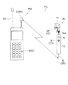
第1実施形態の電話装置PSは、図1及び図2に示すように、据え置き型の電話装置にて構成されて、公衆電話回線又は構内電話回線(以下、単に「電話回線」という)を通じて他の電話装置と通信を行う本体部MUと、その本体部MUに対して無線通信により音声信号の送受を行う通話器SUとを備えて構成されている。
本体部MUには、図1及び図2に示すように、通話器SUと無線通信するための本体側アンテナ1及び送受信回路2、送受信回路2等を介して通話器SUとの間で音声信号の送受を行うと共に、電話回線に接続するためのコネクタ3を介して通話の相手方の電話装置と音声信号の送受を行う制御・駆動回路4、並びに、通話スイッチ5a,切断スイッチ5b及び電話番号入力用キーボード5cを備えたキー操作部5が備えられている。従って、本体側アンテナ1及び送受信回路2を備えて、通話器SUと無線通信するための本体部側無線通信装置MRが構成され、制御・駆動回路4も本体部側無線通信装置MRの一部として機能する。
【0013】
通話器SUには、図1及び図2に示すように、本体部MUと無線通信するための通話器側アンテナ6及び送受信回路7、送受信回路7等を介して本体部MUとの間で音声信号の送受を行う制御・駆動回路8、通話スイッチ9、通話の相手方から電話がかかってきたことを報知するための着信表示ランプ10、通話の相手方の音声を放音するスピーカ11、電話装置PSの使用者の音声を検出するマイク12、並びに、図示しない電池等が備えられている。従って、通話器側アンテナ6及び送受信回路7を備えて、本体部側無線通信装置MRと無線通信するための通話器側無線通信装置SRが構成され、制御・駆動回路8も通話器側無線通信装置SRの一部として機能する。
【0014】
図1に示すように、通話器SUは、スピーカ11及びマイク12が一体に形成されると共に、上記送受信回路7及び制御駆動回路8等が通話器用筐体13内に収納され、通話器用筐体13の下部から通話器側アンテナ6が下方に延出している。又、通話器用筐体13の表面に通話スイッチ9及び着信表示ランプ10が備えられている。
通話器SUに備えられるマイク12は、声帯から耳部への音声振動すなわち骨伝導音声を検出する音声振動検出装置AP及び音声振動検出装置APの検出信号を信号処理等する信号処理回路SPが備えられて構成されている。
【0015】
この音声振動検出装置APは、図3及び図5に示すように、それのハウジング14内に、夫々略棒状に形成され且つ一端を半田付けにて接続した2つの圧電素子15と、その圧電素子15の周囲を覆うと共にその一端を強固に保持する電磁シールドケース16とが備えられて構成されている。
ハウジング14は、骨伝導音声を的確に伝えるために硬質であり、且つ、湿度を保持し易い材料にて形成されると共に、その表面は鏡面状に磨き上げられて形成されて、皮膚との密着性を向上させている。尚、この湿度を保持し易い材料としては、ポリアミド系樹脂、ABS樹脂等があり、特にABS樹脂は良好な成形性を有し、低価格であるので好適である。
電磁シールドケース16は、S/N比向上のためのものであり、又、骨伝導音声を的確に圧電素子15に伝えるために、電磁シールドケース16等を保護するハウジング14に強固に支持されている。
各圧電素子15は、図6に示すように、分極加工した2枚の圧電セラミック材15aにてシム材15bを挟持する状態となるように導電性接着材にて貼り合わせたものであり、いわゆるバイモルフ型の圧電素子を構成している。
【0016】
信号処理回路SPは、図7に示すように、圧電素子15の検出信号が入力されて主にインピーダンス変換を行うFET17及び図示しないコンデンサ等の回路部品から構成され、これらの回路部品は、図3に示すように、回路基板18上に実装されている。FET17の出力信号(ドレーン−ソース間の信号)は、上記制御駆動回路8に入力される。尚、この回路基板18も上記電磁シールドケース16内に収納されている。
【0017】
通話器SUに備えられるスピーカ11は、図3に示すように、イヤホン型に構成され、ダイナミックスピーカ型の小型スピーカユニット19と、その小型スピーカユニット19の前面を覆うように配置されて小型スピーカユニット19を保護するプロテクタ20と、小型スピーカユニット19の後部側を保持してスピーカ11のハウジングとしても機能する制振部材21とが備えられて構成される。この制振部材21は、小型スピーカユニット19にて発生する機械的微振動を可及的に吸収し減衰させるために、黄銅や鉄等の比較的比重が大きく、又、安価な金属にて構成してあり、支持部材22に支持される。
【0018】
支持部材22は、スピーカ11の制振部材21とマイク12を構成する音声振動検出装置APのハウジング14とが二股状となるように支持するものであり、スピーカ11からマイク12への機械的振動の伝達を抑制する構造となっており、又、支持部材22の内部にスピーカ11及びマイク12と制御・駆動回路8との結ぶ信号線を通し、これらを保護する機能をも有する。
支持部材22には、スピーカ11及びマイク12の耳部への装着状態を安定させるための挟持部材23が取り付けられている。この挟持部材23は、粘弾性特性を有する材料、具体的には、硬度30度から110度程度のゴム材や塩化ビニル等の材料にて構成されている。
【0019】
上記構成の通話器SUは、図8及び図9に示すように、スピーカ11及びマイク12を耳部に装着されて使用され、装着状態においては、上記通話器用筐体13は、支持部材22を経由してハウジング14から下方に垂下する信号線14aにて吊下げ支持される。従って、使用者は、通話器SUを手等で支える必要がなく、両手を自由に使用できる。
人の耳部はおよそ図10に示すような構造をしており、スピーカ11及びマイク12は、図8及び図9に示すように、耳甲介腔部24内にそれと接触する状態に装着され、耳甲介腔部24に連なる対珠25と耳珠26とに抱えこまれること、及び、ハウジング14と挟持部材23とによって耳甲介腔部24の縁部24aを挟持することによって安定的に支持される。
この装着状態において、音声振動検出装置APのハウジング14は、図9に示すように、耳甲介腔部24内の各位置のうち最も声帯に近く効率良く骨伝導音声を検出できる位置である底部24bに接当しており、その底部24bから骨伝導音声を検出するのであるが、この検出を効率良く行えるようにするために、図5に示すように、ハウジング14における耳甲介腔部24の底部24bとの接当面(下側の面)は、下側に凸形状として耳甲介腔部24の底部24bの形状と適合させて接触面積を可及的に広くしている。
【0020】
又、上記装着状態においては、スピーカ11及びマイク12の重心位置は、ハウジング14と挟持部材23とによる耳甲介腔部24の縁部24aの保持位置よりも耳甲介腔部24内方側に位置しており、マイク11及びスピーカ12による荷重、及び、挟持部材23等による挟持力にて、ハウジング14が耳甲介腔部24の底部24bに的確に接触維持される。尚、スピーカ11等により耳甲介腔部24の底部24bにかかる荷重としては、皮膚の凹凸や皮膚の体毛の影響を除去し得るのに十分は大きさであり、且つ、荷重が過大となって使用者に不快感を与えないものとするため、数グラムから20グラム程度となるように設定してある。
一方、スピーカ11は、上記装着状態において、小型スピーカユニット19の放音面側が耳部の外耳道27に対面しており、通話の相手方の音声等を外耳道27に向けて放音する。
【0021】
次に、電話装置PSの動作を、使用者の操作と関係付けて説明する。
先ず、通話の相手方から電話がかかってきた場合を説明する。
コネクタ3を介して電話回線から呼び出し信号を受信すると、制御・駆動回路4は、本体側アンテナ1及び送受信回路2から、この呼び出し信号を送信させる。
通話器SU側では、通話器側アンテナ6及び送受信回路7がこの呼び出し信号を受信すると、制御・駆動回路8は、呼び出し信号を着信表示ランプ10及びスピーカ11に送り、呼び出し音を鳴らせると共に着信表示ランプ10を点滅させる。
【0022】
使用者は、呼び出し音あるいは着信表示ランプ10の点滅によって電話がかかてきたことを認識すると、適宜通話器SUを耳部に装着すると共に、通話器用筐体13を手にもって、通話スイッチ9を押し操作する。
この操作によって、通話器SUの制御・駆動回路8は、通話スイッチ9が押し操作された旨の信号を通話器側アンテナ6及び送受信回路7から送信させる。
本体部MUは、この信号を受信すると、制御・駆動回路4が、電話回線側との所定の通信により通話可能な状態に移行させ、本体部MUと通話器SUとの間で、送受信回路2,7、本体側アンテナ1及び通話器側アンテナ6を介して、通話の相手方の音声信号と使用者の音声信号が送受される状態とする。
従って、通話器SUの通話スイッチ9は、通話の開始を指示するための通話指令スイッチCSとして機能する。
尚、本体部MUの通話スイッチ5aが押し操作されたときも、上記と同様にして相手方との通話が可能となる。
【0023】
上述のような使用形態での通話が終了すると、使用者は、通話器SUの通話スイッチ9を再度押し操作する。
通話器SUの制御・駆動回路8は、通話スイッチ9が再度押し操作されると、その旨の信号を通話器側アンテナ6及び送受信回路7から送信させる。
本体部MUは、この信号を受信して、制御・駆動回路4が、電話回線側との通信を切断する。尚、本体部MUの切断スイッチ5bが押し操作されたときも上記と同様にして通信が切断される。
【0024】
次に、電話装置PSの使用者から通話の相手方へ電話をかける場合について説明する。
この場合は、使用者は、本体部MUの通話スイッチ5aを押し操作した後、通話の相手方に対応する電話番号を電話番号入力用キーボード5cにて押し操作するか、あるいは、通話の相手方に対応する電話番号を電話番号入力用キーボード5cにて押し操作した後、通話スイッチ5aを押し操作する。
制御・駆動回路4は、通話スイッチ5aが押し操作されるに伴って、電話番号入力用キーボード5cにて押し操作された電話番号を電話回線側に対して入力可能な状態としている。尚、電話番号入力用キーボード5c又は制御・駆動回路4には、電話番号入力用キーボード5cにて押し操作された電話番号を一時的に記憶するバッファメモリが備えられている。
このように電話回線側に対して電話番号が入力された後、通話の相手方が受話器をとると、両者の間で会話が可能な状態となる。
この通話時における通話器SUの使用形態は、上述の電話がかかってきた場合と同様である。
【0025】
又、通話の相手方に電話をかける操作としては、通話器SUの通話スイッチ9を押し操作しても良い。通話スイッチ9が押し操作されると、制御・駆動回路8が、通話スイッチ9が押し操作された旨の信号を、通話器側アンテナ6及び送受信回路7から送信させる。
本体部MUの制御・駆動回路4が、本体側アンテナ1及び送受信回路2を介して、この信号を受け取ると、制御・駆動回路4は、上述の通話スイッチ5aが押し操作されたときと全く同様の処理を行い、電話回線側に対して電話番号を入力可能とする。
使用者と通話の相手方との会話が終了し、本体部MUの切断スイッチ5b又は通話器SUの通話スイッチ9が押し操作された場合には、上述の使用者側から電話をかける場合と同様にして電話回線側との通信が切断される。
【0026】
〔第2実施形態〕
本第2実施形態は、本体部MUを据え置き型の電話装置として構成している点で上記第1実施形態と共通するが、本第2実施形態では、本体部側無線通信装置MRを構成する本体側アンテナ1及び送受信回路2を、送受信ユニットRUとして、本体部MUの本体部用筐体30と別体に構成している点で、本体部MUの筐体内に本体部側無線通信装置MRを収納する構成とする上記第1実施形態と異なる。
【0027】
すなわち、第2実施形態の電話装置PSは、電話用送受話器HS(以下、「ハンドセットHS」と称する)と上記送受信ユニットRUとが、ハンドセットHSに備えられるコードL1によって接続され、送受信ユニットRUと本体部用筐体30とがコードL2によって接続されている。送受信ユニットRUの通信線CLであるコードL2は、本体部用筐体30に備えられる音声信号入出力端子IOであるコネクタ30aに接続されるのであるが、このコネクタ30aは、本来、ハンドセットHSのコードL1が接続されるものを利用している。
【0028】
電話装置PSのブロック構成図を図12に示すが、図12においては、上記第1実施形態におけるものと同様の機能を有するものは、同一の符号を付している。
送受信ユニットRUには、上記の本体側アンテナ1及び送受信回路2の他に、図11にも示すフック釦31及びフック釦31と連動する切換スイッチ32が備えられている。
この切換スイッチ32は、コードL2をハンドセットHS側に接続するか、あるいは、送受信回路2側に接続するかを切換えるためのスイッチであり、ハンドセットHSを送受信ユニットRUのフック釦31に乗せたときには、コードL2を送受信回路2側に接続し、ハンドセットHSをフック釦31に乗せていないときは、コードL2をハンドセットHS側に接続する。
第2実施形態の通話器SUは、基本的には、上記第1実施形態における通話器SUをそのまま利用する場合を例示しているが、後述のように制御・駆動回路8の作動が若干異なり、又、通話スイッチ9及び着信表示ランプ10は必ずしも必要ない。
【0029】
次に、電話装置PSの動作を簡単に説明する。
先ず、通話の相手方から電話がかかってきた場合を説明する。
待機状態では、ハンドセットHSは本体部用筐体30に備えられているフック釦30b上に乗せられた状態としてあり、コネクタ3を介して電話回線から呼び出し信号を受信すると、制御・駆動回路4は、図示しないスピーカに呼び出し音を鳴らせる。
使用者は、この呼び出し音によって電話がかかってきたことを認識すると、本体部用筐体30からハンドセットHSを持ち上げる。
制御・駆動回路4は、フック釦30bがこの操作を検出すると、電話回線側との所定の通信により通話可能な状態に移行させ、使用者は、ハンドセットHSによって相手方との通話を行える。
【0030】
一方、使用者が本体部用筐体30から持ち上げたハンドセットHSを送受信ユニットRUのフック釦31に乗せた場合は、上述のようにコードL2は送受信回路2に接続され、送受信アンテナANである本体側アンテナ1,送受信回路2及びこれらに対する通信制御部CCとして機能する制御・駆動回路4にて構成される本体部側無線通信装置MRと、通話器側アンテナ6,送受信回路7及び制御・駆動回路8にて構成される通話器側無線通信装置SRとの間で、使用者と相手方との通話が送受信される状態となる。従って、使用者は、通話器SUを耳部に装着して、相手方と通話を行える。
上述のような使用形態での通話が終了すると、使用者は、ハンドセットHSを送受信ユニットRUのフック釦31から本体部用筐体30のフック釦30bに乗せ換え、制御・駆動回路4が、フック釦30bの状態からこの操作を検出すると、電話回線側との通信を切断する。
【0031】
又、電話装置PSの使用者から通話の相手方へ電話をかける場合においては、ハンドセットHSを本体部用筐体30のフック釦30bから持ち上げた後、通話の相手方に対応する電話番号を電話番号入力用キーボード5cにて押し操作すると、制御・駆動回路4は、この操作に伴って、電話回線側に対して電話番号を入力し、通話の相手方が受話器をとると、両者の間で会話が可能な状態となる。
この通話の際の形態は、上述の電話がかかってきた場合と同様であり、上述のようにハンドセットHSにてそのまま通話を行う形式と、ハンドセットHSを送受信ユニットRUのフック釦31に乗せ換えて、通話器RUを使用して通話を行う形式とを選択できる。
【0032】
〔第3実施形態〕
本第3実施形態は、本体部MUを携帯式の無線電話装置として構成している点で、本体部MUを据え置き型の電話装置にて構成する第1実施形態と異なる。
【0033】
本体部MUを携帯式の無線電話装置とすることで、図13及び図14に示すように、本第3実施形態における本体部MUは、上記第1実施形態におけるコネクタ3の代わりに基地局との通信を行うための主アンテナ40及び主送受信回路41が備えられている。
その他の構成部分で、上記第1実施形態と同一の機能を有するものは、上記第1実施形態と同一の符号を付している。
通話器SUは、上記第1実施形態における通話器SUと同一である。
【0034】
次に、電話装置PSの動作を使用者の操作と関係付けて概略的に説明する。
先ず、通話の相手方から電話がかかってきた場合を説明する。
基地局等からの無線通信による呼び出し信号を主アンテナ40及び主送受信回路41にて受信すると、制御・駆動回路4は、本体側アンテナ1及び送受信回路2から、この呼び出し信号を送信させる。これに伴って、上記第1実施形態と同様に、通話器SU側で呼び出し音が鳴り、着信表示ランプ11が点滅する。
使用者は、呼び出し音あるいは着信表示ランプ11の点滅によって電話がかかてきたことを認識すると、通話器SUを耳部の装着すると共に、通話スイッチ9を押し操作する。
【0035】
この操作によって、上記第1実施形態と同様にして、基地局等との所定の通信により通話可能な状態に移行され、本体側アンテナ1,送受信回路2及び制御・駆動回路4にて構成される本体部側無線通信装置MRと、通話器側アンテナ6,送受信回路7及び制御・駆動回路8にて構成される通話器側無線通信装置SRとの間で、通話の相手方の音声信号と使用者の音声信号が送受される状態となる。従って、電話装置PSの使用者は、例えば、本体部MUを鞄の中に入れた状態であっても、小型の通話器SUを服のポケット等に入れておけば、通話の相手方から電話がかかってきたときに、その都度本体部MUを鞄から取り出すというような作業が不要となり、取扱いが便利なものとなる。
尚、本体部MUが使用者の手もとにある等により、本体部MUの通話スイッチ5aが押し操作されたときも、上記と同様にして相手方との通話が可能となる。
【0036】
通話時における通話器SUの使用形態、及び、通話を終了した場合の処理、更には、電話装置PSの使用者側から通話の相手方に電話をかける場合の動作等は上記第1実施形態と同様であり説明を省略する。
尚、本第3実施形態では、電話装置PSの使用者は、通話器SUを使用して相手方と会話するものとしているが、本体部MUにスピーカ及びマイクロホンを備えて、本体部MU単体で通話を行えるようにしても良い。
【0037】
〔第4実施形態〕
本第4実施形態は、上記第3実施形態と同様に本体部MUが携帯式の無線電話装置にて構成される点で共通するが、本第4実施形態では、本体部側無線通信装置MRを構成する本体側アンテナ1及び送受信回路2を、送受信ユニットRUとして、本体部MUの本体部用筐体30と別体に構成している点で、本体部MUの筐体内に本体部側無線通信装置MRを収納する構成とする上記第3実施形態と異なる。
すなわち、第4実施形態の電話装置PSは、図15及び図16に示すように、受信ユニットRUと本体部用筐体30とがコードL3によって接続されている。送受信ユニットRUの通信線CLであるコードL3は、本体部用筐体30に備えられる音声信号入出力端子IOであるジャック50に接続される。このジャック50は、一般的に備えられるマイク/イヤホン端子を利用している。尚、第4実施形態における通話器SUは、第3実施形態における通話器SUの構成と基本的に共通であるので、図16に示すブロック構成図では、本体部MUの構成のみを示しており、又、上記第3実施形態におけるものと同様の機能を有するものは、同一の符号を付している。
【0038】
次に、電話装置PSの動作を簡単に説明する。
基地局等からの無線通信による呼び出し信号を主アンテナ40及び主送受信回路41にて受信すると、制御・駆動回路4は、本体側アンテナ1及び送受信回路2から、この呼び出し信号を送信させる。これに伴って、上記第1実施形態と同様に、通話器SU側で呼び出し音が鳴り、着信表示ランプ11が点滅する。
使用者は、呼び出し音あるいは着信表示ランプ11の点滅によって電話がかかてきたことを認識すると、通話器SUを耳部に装着すると共に、通話スイッチ9を押し操作する。
【0039】
制御・駆動回路4は、送受信回路2から入力される音声信号に上記通話スイッチ9が押し操作された旨の信号が含まれていると、上記第3実施形態と同様に、基地局等との所定の通信により通話可能な状態に移行され、送受信アンテナANである本体側アンテナ1,送受信回路2及びこれらに対する通信制御部CCとして機能する制御・駆動回路4にて構成される本体部側無線通信装置MRと、通話器側アンテナ6,送受信回路7及び制御・駆動回路8にて構成される通話器側無線通信装置SRとの間で、通話の相手方の音声信号と使用者の音声信号が送受される状態となる。
尚、本体部MUが使用者の手もとにある等により、本体部MUの通話スイッチ5aが押し操作されたときも、上記と同様にして相手方との通話が可能となる。
【0040】
通話時における通話器SUの使用形態、及び、通話を終了した場合の処理、更には、電話装置PSの使用者側から通話の相手方に電話をかける場合の動作等は上記第3実施形態と同様であり説明を省略する。
尚、送受信ユニットRUのコードL3をジャック50から離脱させると、本体部MUは、通常の携帯式の電話装置として利用でき、スピーカ51及びマイクロホン52にて通話を行える。
【0041】
本第4実施形態では、本体部MUは、本体部用筐体30と送受信ユニットRUとが別体に構成されているが、この本体部MUの携帯のために、図17に示すように、本体部用筐体30と送受信ユニットRUと収納する収納ケース61が備えられている。
収納ケース61は、図17に示すように、ベルト60に装着可能としてある。又、図18に示すように、収納ケース61に、通話器SUを収納する通話器収納部62を備えて、通話器SUをも収納できるようにしても良い。
【0042】
〔その他の実施形態〕
以下、その他の実施形態を列記する。
▲1▼ 上記各実施形態では、音声振動検出装置APは、圧電素子15にて骨伝導音声を検出する構成としているが、例えば、容量変化型の振動計等により構成しても良い。
▲2▼ 上記各実施形態では、通話器側無線通信装置SRを収納する通話器用筐体13を信号線14aにて吊下げ支持させる構成としているが、信号線14aの長さを十分長くして、スピーカ11及びマイク12を耳部に装着した状態でも、通話器用筐体13を使用者の衣服のポケット等に収納できるように構成しても良い。
▲3▼ 上記第2実施形態では、ハンドセットHSを送受信ユニットRUのフック釦31に乗せるか否かで、ハンドセットHSにより通話を行うか、あるいは、通話器SUにより通話を行うかの切換えを行う構成としている、ハンドセットHS及び通話器SUの両方で通話を行えるように構成しても良い。
【図面の簡単な説明】
【図1】本発明の第1実施形態にかかる電話装置の全体構成図
【図2】本発明の第1実施形態にかかる電話装置のブロック構成図
【図3】本発明の第1実施形態にかかる要部部分断面図
【図4】本発明の第1実施形態にかかる要部正面図
【図5】本発明の第1実施形態にかかる音声振動検出装置の拡大断面図
【図6】本発明の第1実施形態にかかる圧電素子の拡大断面図
【図7】本発明の第1実施形態にかかる回路構成図
【図8】本発明の第1実施形態にかかる通話器の装着状態を示す図
【図9】本発明の第1実施形態にかかる通話器の装着状態を示す図
【図10】人の耳部における各部位の名称説明図
【図11】本発明の第2実施形態にかかる電話装置の全体構成図
【図12】本発明の第2実施形態にかかる電話装置のブロック構成図
【図13】本発明の第3実施形態にかかる電話装置の全体構成図
【図14】本発明の第3実施形態にかかる電話装置のブロック構成図
【図15】本発明の第4実施形態にかかる電話装置の全体構成図
【図16】本発明の第4実施形態にかかる本体部のブロック構成図
【図17】本発明の第4実施形態にかかる電話装置の収納状態を示す図
【図18】本発明の第4実施形態にかかる電話装置の収納状態を示す図
【符号の説明】
AP 音声振動検出装置
AN 送受信アンテナ
CC 通信制御部
CL 通信線
CS 通話指令スイッチ
MR 本体部側無線通信装置
MU 本体部
IO 音声信号入出力端子
RU 送受信ユニット
SU 通話器
SR 通話器側無線通信装置
11 スピーカ
12 マイク
13 通話器用筐体
14 ハウジング
14a 信号線
21 ハウジング
23 挟持部材
30 本体部用筐体
61 収納ケース
62 通話器収納部[0001]
BACKGROUND OF THE INVENTION
The present invention provides a telephone device comprising a main body that communicates with another telephone device, and a communication device that transmits and receives audio signals to and from the main body.And a transceiver unit for wireless communication with a telephoneAbout.
[0002]
[Prior art]
Such a telephone device is provided with a main body side wireless communication device for wirelessly communicating with a telephone having a microphone and a speaker in a main body that communicates with other telephone devices, Is provided with a talker-side radio communication device for communicating with the main body side radio communication device. That is, the main unit corresponds to a so-called cordless telephone base unit, and the telephone set corresponds to a handset. By configuring the telephone device in this way, the user of the telephone device can By using it, it is not subject to much restrictions on the position to be used, and is convenient.
By the way, conventionally, the microphone provided in the telephone has generally used a so-called air-conduction type microphone that picks up sound that is emitted from the mouth of the user and propagates in the air.
[0003]
[Problems to be solved by the invention]
Therefore, in the conventional configuration, the speaker and the air conduction type microphone are placed in an ergonomic position determined by CCITT or EIA, that is, the speaker is close to the user's ear, and the air conduction type microphone is the user's mouth. There is a disadvantage that the shape of the telephone set becomes large.
In addition, the air-conduction microphone detects not only the voice emitted by the user but also ambient noise, etc., which causes noise that degrades the quality of the transmitted voice, making it difficult for the other party to hear the call. There was also an inconvenience.
The present invention has been made in view of the above circumstances, and an object thereof is to improve the call quality as much as possible and to reduce the size of the telephone.
[0004]
[Means for Solving the Problems]
With the configuration of the above-described
In addition, even when the main body unit is not equipped with a transmission / reception circuit for wireless communication with the telephone, the voice input / output terminal which is the first connector connected to the communication control unit generally provided in the main body unit, By connecting a transmission / reception unit including a main body side wireless communication device for wireless communication with a telephone, wireless communication between the main body and the telephone can be performed. For this reason, even a conventional telephone device that does not have a wireless communication function with a telephone can be used as it is or with a slight modification.
Further, the transmission / reception unit has a hook button, a second connector connected to the handset, a hook button, a first connector, a second connector, and a changeover switch connected to the main body side wireless communication device. Yes. Then, when the hook button is pressed, the changeover switch connects the main body side wireless communication device to the communication control section of the main body portion via the first connector. When the hook button is not pressed, the second connector connected to the handset is connected to the communication control device of the main body via the first connector. As described above, the connection state between the communication control circuit and the handset or the telephone can be switched by the changeover switch, so that a mode for making a call as it is on the handset and a mode for making a call on the telephone are selected as necessary. It becomes possible.
[0006]
The above claims2With the configuration described above, when the user operates the call command switch of the telephone when the main body receives a call signal from the other party of the call, the main body side wireless communication device and the communication device side wireless communication device The transmission / reception of a voice signal for a call with the other party is started.
Therefore, taking advantage of the small size of the telephone as described above, if the user holds the telephone, when the user receives a call from the other party, the user is placed away from the main body. Even if it is located, it is possible to use the telephone apparatus such that the telephone call command switch of the telephone intercom is operated to immediately start a telephone call, and the telephone device can be made more convenient.
[0011]
The above claims3Thus, the main body is configured by a stationary telephone device.
In many cases, the main body of such a telephone device is generally placed on an office desk or the like, but in such a case, as described above, the telephone is small and the position of the user is large. It is possible to make a call while maintaining an attitude that makes it easy to continue work even when a call is received, and to refer to materials, etc., and it is extremely effective to downsize the telephone as described above. .
In addition, by providing the configuration of
The transmission / reception unit includes a hook button, a connector connected to the handset, and a changeover switch connected to the hook button and the connector. The changeover switch connects the wireless communication device to the main unit when the hook button is pressed. If the hook button is not pressed, the connector connected to the handset is connected to the main body. As described above, the connection state between the main unit and the wireless communication device or the handset can be switched by the changeover switch, so that a mode for making a call as it is on the handset and a mode for making a call on the telephone are selected as necessary. It becomes possible.
Further, the microphone included in the telephone set is configured to include a voice vibration detection device that is mounted in a state in contact with the concha cavity of the human ear and detects voice vibration from the vocal cords. A voice vibration detection device for detecting voice vibration from the voice is detected and so-called bone conduction voice transmitted from the vocal cords to the ear portion by bone conduction is detected. Therefore, it is not necessary to arrange the microphone near the user's mouth, the microphone and the speaker can be arranged close to each other, and the size of the telephone can be reduced. In addition, since the microphone of the communication device detects bone conduction sound, detection of ambient noise is sufficiently suppressed. Accordingly, it has become possible to provide a telephone device that can improve the call quality as much as possible and can reduce the size of the telephone.
[0012]
DETAILED DESCRIPTION OF THE INVENTION
Hereinafter, embodiments of the present invention will be described with reference to the drawings.
[First Embodiment]
As shown in FIGS. 1 and 2, the telephone device PS according to the first embodiment is composed of a stationary telephone device, and is connected through a public telephone line or a private telephone line (hereinafter simply referred to as “telephone line”). A main unit MU that communicates with the telephone device, and a telephone unit SU that transmits and receives voice signals to and from the main unit MU by wireless communication.
As shown in FIG. 1 and FIG. 2, the main unit MU has a voice signal to and from the telephone set SU via the main
[0013]
As shown in FIG. 1 and FIG. 2, a voice signal is transmitted to and from the main unit MU via the communication
[0014]
As shown in FIG. 1, a speaker SU includes a
The
[0015]
As shown in FIGS. 3 and 5, the audio vibration detection device AP includes two
The
The
As shown in FIG. 6, each
[0016]
As shown in FIG. 7, the signal processing circuit SP is mainly composed of a circuit component such as an
[0017]
As shown in FIG. 3, the
[0018]
The
A clamping
[0019]
As shown in FIGS. 8 and 9, the communication device SU having the above-described configuration is used with the
The human ear has a structure as shown in FIG. 10, and the
In this wearing state, the
[0020]
Further, in the mounted state, the positions of the center of gravity of the
On the other hand, in the mounted state, the
[0021]
Next, the operation of the telephone device PS will be described in relation to the user's operation.
First, a case where a call is received from the other party of the call will be described.
When the call signal is received from the telephone line via the connector 3, the control /
On the side of the handset SU, when the handset-
[0022]
When the user recognizes that the telephone call has been made by the ringing tone or the flashing of the incoming
By this operation, the control / drive circuit 8 of the intercom SU transmits the signal indicating that the
When the main unit MU receives this signal, the control /
Accordingly, the
Even when the
[0023]
When the phone call in the above-described usage mode is completed, the user presses the
When the
The main unit MU receives this signal, and the control /
[0024]
Next, a case where a user of the telephone device PS makes a call to the other party of the call will be described.
In this case, after the user presses the
The control /
After the telephone number is input to the telephone line in this way, when the other party of the call picks up the receiver, the conversation between the two becomes possible.
The mode of use of the communication device SU at the time of this call is the same as that when the above-mentioned call is received.
[0025]
Further, as an operation for making a call to the other party of the call, the
When the control /
When the conversation between the user and the other party of the call is terminated and the
[0026]
[Second Embodiment]
The second embodiment is common to the first embodiment in that the main body MU is configured as a stationary telephone device. However, in the second embodiment, the main body wireless communication device MR is configured. The main body side wireless communication device MR is provided in the main body MU in that the main
[0027]
That is, in the telephone device PS of the second embodiment, a telephone handset HS (hereinafter referred to as “handset HS”) and the transmission / reception unit RU are connected by a cord L1 provided in the handset HS, The
[0028]
FIG. 12 shows a block diagram of the telephone device PS. In FIG. 12, components having the same functions as those in the first embodiment are given the same reference numerals.
In addition to the
This change-
The communication device SU of the second embodiment basically illustrates the case where the communication device SU in the first embodiment is used as it is, but the operation of the control / drive circuit 8 is slightly different as will be described later. Further, the
[0029]
Next, the operation of the telephone device PS will be briefly described.
First, a case where a call is received from the other party of the call will be described.
In the standby state, the handset HS is placed on the
When the user recognizes that a call is received by the ringing tone, the user lifts the handset HS from the
When the
[0030]
On the other hand, when the user places the handset HS lifted from the
When the telephone conversation in the above-described usage mode ends, the user changes the handset HS from the
[0031]
When making a call from the user of the telephone device PS to the other party of the call, after the handset HS is lifted from the
The form of this call is the same as that when the above-mentioned telephone is received. As described above, the form in which the telephone is directly communicated with the handset HS and the handset HS are transferred to the
[0032]
[Third Embodiment]
The third embodiment is different from the first embodiment in which the main body MU is configured as a stationary telephone device in that the main body MU is configured as a portable wireless telephone device.
[0033]
By making the main body MU a portable radiotelephone device, as shown in FIGS. 13 and 14, the main body MU in the third embodiment is connected to the base station instead of the connector 3 in the first embodiment. A
Other components having the same functions as those of the first embodiment are denoted by the same reference numerals as those of the first embodiment.
The communication device SU is the same as the communication device SU in the first embodiment.
[0034]
Next, the operation of the telephone device PS will be schematically described in relation to the user's operation.
First, a case where a call is received from the other party of the call will be described.
When the
When the user recognizes that a telephone call has been made by the ringing tone or the flashing of the incoming
[0035]
As a result of this operation, as in the first embodiment, the state is changed to a state in which a call can be made by predetermined communication with a base station or the like, and is configured by the
Even when the
[0036]
The use mode of the telephone SU during a call, the processing when the call is terminated, and the operation when making a call from the user side of the telephone device PS to the other party of the call are the same as in the first embodiment. Therefore, explanation is omitted.
In the third embodiment, the user of the telephone device PS talks with the other party using the telephone SU, but the main body MU includes a speaker and a microphone, and the main body MU alone makes a call. You may be able to do.
[0037]
[Fourth Embodiment]
The fourth embodiment is similar to the third embodiment in that the main body unit MU is configured by a portable wireless telephone device, but in the fourth embodiment, the main body unit side wireless communication device MR. The main
That is, in the telephone device PS of the fourth embodiment, as shown in FIGS. 15 and 16, the receiving unit RU and the main body casing 30 are connected by the cord L3. The cord L3 that is the communication line CL of the transmission / reception unit RU is connected to a
[0038]
Next, the operation of the telephone device PS will be briefly described.
When the
When the user recognizes that a telephone call has been made by the ringing tone or the flashing of the incoming
[0039]
If the voice signal input from the transmission /
Even when the
[0040]
The usage mode of the telephone set SU at the time of the call, the processing when the call is terminated, and the operation when making a call from the user side of the telephone device PS to the other party of the call are the same as in the third embodiment. Therefore, explanation is omitted.
When the cord L3 of the transmission / reception unit RU is detached from the
[0041]
In the fourth embodiment, the main body unit MU includes the main
As shown in FIG. 17, the
[0042]
[Other Embodiments]
Other embodiments will be listed below.
{Circle around (1)} In each of the embodiments described above, the sound vibration detection device AP is configured to detect the bone conduction sound by the
(2) In each of the above embodiments, the
(3) In the second embodiment described above, a configuration for switching between making a call with the handset HS or making a call with the caller SU depending on whether the handset HS is put on the
[Brief description of the drawings]
FIG. 1 is an overall configuration diagram of a telephone device according to a first embodiment of the present invention.
FIG. 2 is a block configuration diagram of the telephone device according to the first embodiment of the present invention.
FIG. 3 is a partial cross-sectional view of a main part according to the first embodiment of the present invention.
FIG. 4 is a front view of main parts according to the first embodiment of the present invention.
FIG. 5 is an enlarged cross-sectional view of the audio vibration detection device according to the first embodiment of the present invention.
FIG. 6 is an enlarged cross-sectional view of the piezoelectric element according to the first embodiment of the present invention.
FIG. 7 is a circuit configuration diagram according to the first embodiment of the present invention.
FIG. 8 is a diagram showing a state in which the communication device according to the first embodiment of the present invention is mounted.
FIG. 9 is a diagram showing a state in which the communication device according to the first embodiment of the present invention is mounted.
FIG. 10 is a diagram illustrating names of parts in a human ear.
FIG. 11 is an overall configuration diagram of a telephone device according to a second embodiment of the present invention.
FIG. 12 is a block diagram of a telephone device according to a second embodiment of the present invention.
FIG. 13 is an overall configuration diagram of a telephone device according to a third embodiment of the present invention.
FIG. 14 is a block configuration diagram of a telephone device according to a third embodiment of the present invention.
FIG. 15 is an overall configuration diagram of a telephone device according to a fourth embodiment of the present invention.
FIG. 16 is a block diagram of a main body according to a fourth embodiment of the present invention.
FIG. 17 is a diagram showing a storage state of the telephone device according to the fourth embodiment of the present invention.
FIG. 18 is a diagram illustrating a storage state of the telephone device according to the fourth embodiment of the present invention.
[Explanation of symbols]
AP sound vibration detector
AN transceiver antenna
CC communication control unit
CL communication line
CS call command switch
MR body side wireless communication device
MU main unit
IO Audio signal input / output terminal
RU transceiver unit
SU telephone
SR wireless communication device for talker side
11 Speaker
12 Microphone
13 Telephone housing
14 Housing
14a signal line
21 Housing
23 Clamping member
30 Main unit housing
61 Storage case
62 Telephone compartment
Claims (4)
前記本体部は、 The main body is
他の電話装置と通信を行うための通信制御部と、 A communication control unit for communicating with other telephone devices;
当該通信制御部と接続された第1のコネクタを有し、 A first connector connected to the communication control unit;
前記送受信ユニットは、 The transceiver unit is:
フック釦と、 A hook button,
ハンドセットと接続された第2のコネクタと、 A second connector connected to the handset;
前記通話器と無線通信するための本体部側無線通信装置と、 A main body side wireless communication device for wireless communication with the telephone,
前記フック釦と、前記第1のコネクタと、前記第2のコネクタと、前記本体部側無線通信装置と接続された切換スイッチを有し、 The hook button, the first connector, the second connector, and a changeover switch connected to the main body side wireless communication device,
前記通話器は、 The telephone is
人の耳部の耳甲介腔部内にそれと接触する状態に装着されて声帯からの音声振動を検出するマイクと、 A microphone that is worn in contact with the concha cavity of the human ear and detects voice vibration from the vocal cords;
スピーカと、 Speakers,
前記本体部側無線通信装置と通信するための通話器側無線通信装置を有し、 A telephone side wireless communication device for communicating with the main body side wireless communication device;
前記切換スイッチは、 The changeover switch is
前記フック釦が押下された場合に、前記本体部側無線通信装置を、前記第1のコネクタを介して前記本体部の通信制御部と接続し、 When the hook button is pressed, the main body unit side wireless communication device is connected to the communication control unit of the main body unit via the first connector,
前記フック釦が押下されていない場合に、前記ハンドセットと接続された第2のコネクタを、第1のコネクタを介して前記本体部の通信制御装置と接続する電話装置。 A telephone device that connects a second connector connected to the handset to a communication control device of the main body via the first connector when the hook button is not pressed.
前記本体部側無線通信装置及び前記通話器側無線通信装置は、前記本体部が通話の相手方からの呼出し信号を受信したときに、前記通話指令スイッチから通話の開始が指示されるに伴って、前記相手からとの通話のための音声信号の送受を開始するように構成されている請求項1記載の電話装置。 The main body unit side wireless communication device and the talker side wireless communication device, when the main body unit receives a call signal from the other party of the call, the start of the call is instructed from the call command switch, The telephone device according to claim 1, wherein the telephone device is configured to start transmission / reception of an audio signal for a call with the other party.
フック釦と、 A hook button,
ハンドセットと接続されたコネクタと、 A connector connected to the handset;
前記通話器と無線通信するための無線通信装置と、 A wireless communication device for wirelessly communicating with the telephone,
前記フック釦及び前記コネクタと接続され、前記フック釦が押下された場合に、前記無線通信装置を前記本体部と接続し、前記フック釦が押下されていない場合に、前記ハンドセットと接続されたコネクタを、前記本体部と接続する切換スイッチを備えた送受信ユニット。 A connector that is connected to the hook button and the connector, connects the wireless communication device to the main body when the hook button is pressed, and connects to the handset when the hook button is not pressed A transmission / reception unit comprising a change-over switch for connecting to the main body.
Priority Applications (1)
| Application Number | Priority Date | Filing Date | Title |
|---|---|---|---|
| JP9323098A JP3789039B2 (en) | 1998-04-06 | 1998-04-06 | Telephone device and transmission / reception unit |
Applications Claiming Priority (1)
| Application Number | Priority Date | Filing Date | Title |
|---|---|---|---|
| JP9323098A JP3789039B2 (en) | 1998-04-06 | 1998-04-06 | Telephone device and transmission / reception unit |
Publications (2)
| Publication Number | Publication Date |
|---|---|
| JPH11289370A JPH11289370A (en) | 1999-10-19 |
| JP3789039B2 true JP3789039B2 (en) | 2006-06-21 |
Family
ID=14076753
Family Applications (1)
| Application Number | Title | Priority Date | Filing Date |
|---|---|---|---|
| JP9323098A Expired - Fee Related JP3789039B2 (en) | 1998-04-06 | 1998-04-06 | Telephone device and transmission / reception unit |
Country Status (1)
| Country | Link |
|---|---|
| JP (1) | JP3789039B2 (en) |
Families Citing this family (4)
| Publication number | Priority date | Publication date | Assignee | Title |
|---|---|---|---|---|
| JP2000349897A (en) * | 1999-04-29 | 2000-12-15 | Pj Telecomm Co Ltd | Earphone-shaped radio telephone set system |
| KR20010007904A (en) * | 2000-10-20 | 2001-02-05 | 임용국 | a mini telephone using wireless transmitter and receiver apparatus and method of communicating thereof |
| NO312989B3 (en) * | 2000-11-01 | 2007-07-04 | Metafax As | Device for wireless transmission between a microphone / earphone and a mobile phone, telephone, switchboard or the like |
| TW517470B (en) * | 2000-11-21 | 2003-01-11 | School Juridical Person Of Fuk | Oscillation preventing circuit |
-
1998
- 1998-04-06 JP JP9323098A patent/JP3789039B2/en not_active Expired - Fee Related
Also Published As
| Publication number | Publication date |
|---|---|
| JPH11289370A (en) | 1999-10-19 |
Similar Documents
| Publication | Publication Date | Title |
|---|---|---|
| US8582755B2 (en) | Headset with a retractable speaker portion | |
| US20060120546A1 (en) | Ear fixed type conversation device | |
| EP1524823A1 (en) | Portable telephone with bone conduction speaker | |
| JPH08181754A (en) | Handset for communication equipment | |
| WO2006113042A1 (en) | Speakerphone with detachable ear bud | |
| JP2000341778A (en) | Handset using bone conduction speaker | |
| JPWO2005096599A1 (en) | Communication device using bone conduction speaker | |
| JP3789039B2 (en) | Telephone device and transmission / reception unit | |
| EP1223682B1 (en) | An electronic device for a mobile radio station | |
| WO2005057888A1 (en) | Wireless headset | |
| JPH1174951A (en) | Slave set connected to radio portable telephone set | |
| US20060172771A1 (en) | Mobile communication peripheral device | |
| WO1999013625A1 (en) | Auxiliary device connected to wireless portable telephone | |
| KR200184608Y1 (en) | Handsfree set for handy phone | |
| JP3798533B2 (en) | Telephone equipment | |
| JP2001168965A (en) | Earphone mount type portable phone and attachment of portable phone | |
| KR20070030391A (en) | Ear microphone for portable terminal | |
| JP3043962U (en) | Telemouse | |
| KR200167709Y1 (en) | Standing telephone having separated transmitter and receiver | |
| KR200286783Y1 (en) | LCD and Dial hansfree earphone | |
| JP3029608U (en) | Earphone microphone for mobile phones | |
| KR200303914Y1 (en) | hands free earphone | |
| KR200202417Y1 (en) | Wireless telephone | |
| JP2000092170A (en) | Mounted wireless telephone set | |
| KR200199056Y1 (en) | Wireless earphone and microphone |
Legal Events
| Date | Code | Title | Description |
|---|---|---|---|
| A621 | Written request for application examination |
Effective date: 20040122 Free format text: JAPANESE INTERMEDIATE CODE: A621 |
|
| A711 | Notification of change in applicant |
Free format text: JAPANESE INTERMEDIATE CODE: A711 Effective date: 20050519 |
|
| A977 | Report on retrieval |
Free format text: JAPANESE INTERMEDIATE CODE: A971007 Effective date: 20051121 |
|
| A131 | Notification of reasons for refusal |
Effective date: 20051129 Free format text: JAPANESE INTERMEDIATE CODE: A131 |
|
| A521 | Written amendment |
Free format text: JAPANESE INTERMEDIATE CODE: A523 Effective date: 20060116 |
|
| TRDD | Decision of grant or rejection written | ||
| A01 | Written decision to grant a patent or to grant a registration (utility model) |
Effective date: 20060322 Free format text: JAPANESE INTERMEDIATE CODE: A01 |
|
| A61 | First payment of annual fees (during grant procedure) |
Free format text: JAPANESE INTERMEDIATE CODE: A61 Effective date: 20060327 |
|
| R150 | Certificate of patent (=grant) or registration of utility model |
Free format text: JAPANESE INTERMEDIATE CODE: R150 |
|
| FPAY | Renewal fee payment (prs date is renewal date of database) |
Free format text: PAYMENT UNTIL: 20100407 Year of fee payment: 4 |
|
| LAPS | Cancellation because of no payment of annual fees |