JP3659081B2 - Double wishbone suspension - Google Patents
Double wishbone suspension Download PDFInfo
- Publication number
- JP3659081B2 JP3659081B2 JP25268999A JP25268999A JP3659081B2 JP 3659081 B2 JP3659081 B2 JP 3659081B2 JP 25268999 A JP25268999 A JP 25268999A JP 25268999 A JP25268999 A JP 25268999A JP 3659081 B2 JP3659081 B2 JP 3659081B2
- Authority
- JP
- Japan
- Prior art keywords
- carrier
- vehicle
- lower arm
- connecting member
- arm
- Prior art date
- Legal status (The legal status is an assumption and is not a legal conclusion. Google has not performed a legal analysis and makes no representation as to the accuracy of the status listed.)
- Expired - Lifetime
Links
Images


Classifications
-
- B—PERFORMING OPERATIONS; TRANSPORTING
- B60—VEHICLES IN GENERAL
- B60G—VEHICLE SUSPENSION ARRANGEMENTS
- B60G3/00—Resilient suspensions for a single wheel
- B60G3/18—Resilient suspensions for a single wheel with two or more pivoted arms, e.g. parallelogram
- B60G3/20—Resilient suspensions for a single wheel with two or more pivoted arms, e.g. parallelogram all arms being rigid
- B60G3/26—Means for maintaining substantially-constant wheel camber during suspension movement ; Means for controlling the variation of the wheel position during suspension movement
-
- B—PERFORMING OPERATIONS; TRANSPORTING
- B60—VEHICLES IN GENERAL
- B60G—VEHICLE SUSPENSION ARRANGEMENTS
- B60G3/00—Resilient suspensions for a single wheel
- B60G3/18—Resilient suspensions for a single wheel with two or more pivoted arms, e.g. parallelogram
- B60G3/20—Resilient suspensions for a single wheel with two or more pivoted arms, e.g. parallelogram all arms being rigid
-
- B—PERFORMING OPERATIONS; TRANSPORTING
- B60—VEHICLES IN GENERAL
- B60G—VEHICLE SUSPENSION ARRANGEMENTS
- B60G2200/00—Indexing codes relating to suspension types
- B60G2200/10—Independent suspensions
- B60G2200/18—Multilink suspensions, e.g. elastokinematic arrangements
-
- B—PERFORMING OPERATIONS; TRANSPORTING
- B60—VEHICLES IN GENERAL
- B60G—VEHICLE SUSPENSION ARRANGEMENTS
- B60G2204/00—Indexing codes related to suspensions per se or to auxiliary parts
- B60G2204/40—Auxiliary suspension parts; Adjustment of suspensions
- B60G2204/41—Elastic mounts, e.g. bushings
Landscapes
- Engineering & Computer Science (AREA)
- Mechanical Engineering (AREA)
- Vehicle Body Suspensions (AREA)
Description
【0001】
【発明の属する技術分野】
本発明は、自動車等車両のサスペンション、特に、ダブルウィシュボーン式サスペンションに関する。
【0002】
【従来の技術】
ダブルウィシュボーン式サスペンションの一つとして、車輪を回転軸線の周りに回転可能に支持するキャリアと、実質的に車両横方向に延在し内端にて車体に枢支され外端にて前記キャリアの上端に枢着されたアッパアームと、少くとも車両前後方向に互いに隔置された二つの内端にて車体に枢支され外端にて前記キャリアの下端に枢着されたロアアームと、内端にて車体に枢支され前記回転軸線より少くとも車両前後方向に隔置された位置にて前記キャリアに枢着されたラテラルリンク(トーコントロールロッドともいう)と、前記ロアアームに連結されるとともに前記キャリアに連結されて前記キャリアの前記アッパアーム及びロアアームに対する相対的な車両前後方向への枢動を可能とする連結部材を有するものがあり、例えば特開平6−344737号公報に示されている。
【0003】
【発明が解決しようとする課題】
上記した公報のダブルウィシュボーン式サスペンションにおいては、良好な車輪支持剛性を有し、しかも四輪操舵装置を備えた車両の車輪にもそのまま適用することができるといった利点があるものの、連結部材として、端部にて中間シャフトと支持シャフトを介してロアアームに車両左右方向に枢動可能に枢着されたインナパイプと、このインナパイプ上に軸線に沿って相対変位可能(伸縮可能)に嵌合されて端部にてボールジョイントを介してキャリアに枢着されるアウタパイプからなるコネクティングリンクが採用されていて、構造が複雑であるため、コストおよび信頼性に課題がある。
【0004】
【課題を解決するための手段】
本発明は、上記した課題に対処すべくなされたものであり、上記したダブルウィシュボーン式サスペンションにおいて、前記連結部材として、前記ロアアーム及びキャリアの何れか一方に連結される内筒と、前記ロアアーム及びキャリアの前記一方とは異なる他方に一体的に連結される外筒と、この外筒と前記内筒との間に介装した弾性変形可能で車両前後左右方向の特性が車両上下方向の特性より柔らかいゴムブッシュからなる連結部材を採用したことに特徴がある。
【0005】
【発明の作用・効果】
本発明によるサスペンションにおいては、車体に対するラテラルリンクの内端の位置を一定に維持することにより、ロアアーム、連結部材、ラテラルリンクは互いに協同して、周知のH型ロアアーム(車両前後方向に互いに隔置された二つの内端にて車体に枢支され、車両前後方向に互いに隔置された二つの外端にてキャリアを枢支する支持剛性の高いロアアーム)と同様に機能し、これにより良好な車輪支持剛性を確保することができる。
【0006】
また、ラテラルリンクの内端を車体に対し相対的に車両横方向に変位させることにより、ラテラルリンクはタイロッドと同様に機能し、これによりキャリアはアッパアーム及びロアアームに対し相対的に車両前後方向に枢動し、車輪の操舵が達成される。したがって、当該サスペンションにおいて、ラテラルリンクをステアリングタイロッドに代えれば、四輪操舵装置を備えた車両の車輪に当該サスペンションをそのまま適用することができる。
【0007】
また、本発明によるサスペンションにおいては、連結部材として、ロアアーム及びキャリアの何れか一方に連結される内筒と、ロアアーム及びキャリアの前記一方とは異なる他方に一体的に連結される外筒と、この外筒と前記内筒との間に介装した弾性変形可能で車両前後左右方向の特性が車両上下方向の特性より柔らかいゴムブッシュからなる連結部材が採用されていて、連結部材がシンプルな構造であるため、安価であり信頼性も高い。
【0008】
また、本発明においては、ゴムブッシュとして、車両前後左右方向の特性が車両上下方向の特性より柔らかいゴムブッシュを採用したため、車輪の回転軸線周りに入力されるモーメント(制動トルク)に対して十分な剛性を得た上で、ストローク時のステア変化(車輪のバウンド・リバウンドに伴うステア変化)、外力負荷時のステア変化(路面から車輪に外力が作用するときのステア変化)をラテラルリンクで最大限にコントロールすることができて、良好なステア特性を得ることが可能である。
【0009】
【発明の実施の形態】
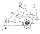
以下に、本発明の一実施形態を図面に基づいて説明する。図1及び図2に概略的に示した本発明によるダブルウィシュボーン式サスペンションは、キャリア11と、アッパアーム13と、ロアアーム15と、ラテラルリンク17と連結部材19を備えるとともに、簡略化するために図示省略した周知のショックアブソーバ及びサスペンションスプリングを備えている。なお、キャリア11、アッパアーム13、ロアアーム15およびラテラルリンク17は、実質的に剛体によって形成されている。
【0010】
キャリア11は、車輪21を回転軸線L1の周りに回転可能に支持するものであり、アッパアーム13及びロアアーム15によって支持されている。アッパアーム13は、I型アームであり、実質的に車両横方向に延在し、内端にてゴムブッシュを含むジョイント23により車体25に枢支され、外端にてボールジョイント27によりキャリア11の上端に枢着されている。
【0011】
ロアアーム15は、実質的にA型アームであり、実質的に車両前後方向及び車両横方向に互いに隔置された二つの内端にてゴムブッシュを含む一対のジョイント31、33によりそれらの共通の軸線L2周りに枢動可能に車体25に枢支され、外端にてボールジョイント35によりキャリア11の下端に枢着されている。ロアアーム15の前側(図1の上側)のジョイント31は後側のジョイント33に対し車両前方且アウトボード方向に隔置されており、後側のジョイント33はボールジョイント35と略一致する車両前後方向位置に位置している。
【0012】
ラテラルリンク17は、ロアアーム15の車両後方側にて実質的に車両横方向に延在し、内端にてゴムブッシュを含むジョイント37により車体25に枢支され、外端にてボールジョイント39によりキャリア11に一体的に設けたアーム部11aの先端に枢着されている。
【0013】
連結部材19は、ロアアーム15に設けた実質的に前後方向に延在する軸41に同軸的に連結される内筒19aと、キャリア11におけるアーム部11aの基部に一体的に連結される外筒19bと、内筒19aと外筒19b間に介装した弾性変形可能なゴムブッシュ19cからなり、ゴムブッシュ19cには、図3に示したように、車両前後左右方向の特性が車両上下方向の特性より柔らかくなるように、径方向に互いに隔置された一対の空洞部(俗に「スグリ」と呼ばれる)19c1、19c2が形成されている。
【0014】
上記のように構成した本実施形態のサスペンションにおいては、車体25に対するラテラルリンク17の内端の位置、即ちジョイント37の位置が一定に維持されると、ロアアーム15はラテラルリンク17及び連結部材19と協同して、車両前後方向及び横方向に互いに隔置された二つの内端にてジョイント31及び33により車体25に枢支され車両前後方向及び横方向に互いに隔置された二つの内端にてボールジョイント35及び39によりキャリア11に枢着されたH型アームと同様に機能する。
【0015】
このため、車輪21に作用する前後力はロアアーム15及びラテラルリンク17により担持され、車輪21に作用する横力はアッパアーム13、ロアアーム15及びラテラルリンク17により担持されるので、特開平6−344737号公報の図1〜図3に示されている実施例のサスペンションと同様に、良好な車輪支持剛性、キャンバコントロール性能、トーコントロール性能を確保することができる。
【0016】
また、本実施形態のサスペンションにおいては、ラテラルリンク17の内端の位置、即ちジョイント37の位置が例えば油圧シリンダ装置の如きアクチュエータによって車体25に対し相対的に車両横方向へ移動されると、キャリア11はロアアーム15の外端のボールジョイント35の中心を通るキングピン軸を中心として、車両の上方より見てロアアーム15及びアッパアーム13に対し相対的に車両前後方向に枢動し、車輪21の操舵が達成される。したがって、当該サスペンションにおいて、ラテラルリンク17をステアリングタイロッドに代えれば、例えば四輪操舵装置を備えた車両の後輪に当該サスペンションをそのまま適用することができる。
【0017】
また、本実施形態のサスペンションにおいては、連結部材19として、ロアアーム15に連結される内筒19aと、キャリア11に連結される外筒19bと、外筒19bと内筒19aとの間に介装した弾性変形可能なゴムブッシュ19cからなるものが採用されていて、連結部材19がシンプルな構造であるため、安価であり信頼性も高い。
【0018】
また、ゴムブッシュ19cとして、車両前後左右方向の特性が車両上下方向の特性より柔らかいものが採用されているため、車輪21の回転軸線L1周りに入力されるモーメント(制動トルク)に対して十分な剛性を得た上で、ストローク時のステア変化(車輪のバウンド・リバウンドに伴うステア変化)、外力負荷時のステア変化(路面から車輪に外力が作用するときのステア変化)をラテラルリンク17で最大限にコントロールすることができて、良好なステア特性を得ることが可能である。
【0019】
上記実施形態においては、ロアアーム15に連結される内筒19aと、キャリア11に連結される外筒19bと、外筒19bと内筒19aとの間に介装した弾性変形可能なゴムブッシュ19cからなる連結部材19を採用して実施したが、キャリアに連結される内筒と、ロアアームに連結される外筒と、外筒と内筒との間に介装した弾性変形可能なゴムブッシュからなる連結部材を採用して本発明を実施することも可能である。
【0020】
また、上記実施形態においては、ゴムブッシュ19cとして、車両前後左右方向の特性が車両上下方向の特性より柔らかいものを採用したが、ゴムブッシュの特性は適宜変更して実施し得るものである。
【図面の簡単な説明】
【図1】 本発明によるダブルウィシュボーン式サスペンションの一実施形態を概略的に示す平面図である。
【図2】 図1に示したサスペンションの背面図である。
【図3】 図1に示した連結部材単体の正面図である。
【符号の説明】
11…キャリア、13…アッパアーム、15…ロアアーム、17…ラテラルリンク、19…連結部材、19a…内筒、19b…外筒、19c…ゴムブッシュ、19c1、19c2…空洞部、21…車輪、25…車体、L1…回転軸線。[0001]
BACKGROUND OF THE INVENTION
The present invention relates to a suspension for a vehicle such as an automobile, and more particularly to a double wishbone suspension.
[0002]
[Prior art]
As one of the double wishbone type suspensions, a carrier that supports a wheel so as to be rotatable around a rotation axis, and a carrier that extends substantially in the lateral direction of the vehicle and is pivotally supported by a vehicle body at an inner end and the carrier at an outer end. An upper arm pivotally attached to the upper end of the vehicle body, a lower arm pivotally supported by the vehicle body at two inner ends spaced from each other in the vehicle longitudinal direction and pivotally attached to the lower end of the carrier at the outer end, and an inner end And a lateral link (also referred to as a toe control rod) pivotally attached to the carrier at a position that is pivotally supported by the vehicle body and spaced apart in the vehicle longitudinal direction at least from the rotational axis, and is connected to the lower arm and Some have a connecting member that is connected to a carrier and allows the carrier to pivot relative to the upper arm and the lower arm in the vehicle longitudinal direction. It disclosed in JP--344737.
[0003]
[Problems to be solved by the invention]
In the double wishbone suspension of the above publication, although there is an advantage that it has good wheel support rigidity and can be applied as it is to a vehicle wheel equipped with a four-wheel steering device, An inner pipe pivotally attached to the lower arm via the intermediate shaft and the support shaft at the end so as to be pivotable in the left-right direction of the vehicle, and fitted on the inner pipe so as to be capable of relative displacement (expandable) along the axis. Since the connecting link consisting of the outer pipe pivotally attached to the carrier via the ball joint at the end is adopted and the structure is complicated, there are problems in cost and reliability.
[0004]
[Means for Solving the Problems]
The present invention has been made to cope with the above-described problem, and in the above-described double wishbone suspension, as the connecting member, an inner cylinder connected to one of the lower arm and the carrier , the lower arm, An outer cylinder integrally connected to the other one of the carriers different from the one, and an elastically deformable intervening between the outer cylinder and the inner cylinder, and the vehicle front-rear and left-right characteristics are higher than the vehicle vertical characteristics It is characterized by adopting a connecting member made of a soft rubber bush.
[0005]
[Operation and effect of the invention]
In the suspension according to the present invention, the position of the inner end of the lateral link with respect to the vehicle body is maintained constant so that the lower arm, the connecting member, and the lateral link cooperate with each other to form a well-known H-type lower arm (separated from each other in the vehicle longitudinal direction). The lower inner arm, which is pivotally supported by the vehicle body at the two inner ends and pivotally supports the carrier at the two outer ends separated from each other in the longitudinal direction of the vehicle, functions in a similar manner. Wheel support rigidity can be ensured.
[0006]
Further, by displacing the inner end of the lateral link in the lateral direction of the vehicle relative to the vehicle body, the lateral link functions in the same manner as the tie rod, whereby the carrier pivots in the longitudinal direction of the vehicle relative to the upper arm and the lower arm. And wheel steering is achieved. Therefore, in the suspension, if the lateral link is replaced with a steering tie rod, the suspension can be applied as it is to the wheel of a vehicle equipped with a four-wheel steering device.
[0007]
In the suspension according to the present invention, as a connecting member, an inner cylinder connected to one of the lower arm and the carrier, an outer cylinder integrally connected to the other one of the lower arm and the carrier, and this A connecting member made of a rubber bush that is elastically deformable and is softer in the longitudinal direction of the vehicle than in the vertical direction of the vehicle is adopted between the outer cylinder and the inner cylinder, and the connecting member has a simple structure. Therefore, it is inexpensive and highly reliable.
[0008]
Further, in the present invention , a rubber bush is used as the rubber bush , which has a characteristic in the vehicle front-rear and left-right directions that is softer than the characteristic in the vehicle vertical direction, so that it is sufficient for the moment (braking torque) input around the rotation axis of the wheel. After obtaining rigidity, the lateral link maximizes the steer change during stroke (steer change associated with wheel bounce / rebound) and the steer change during external force load (steer change when external force acts on the wheel from the road surface). Therefore, good steer characteristics can be obtained.
[0009]
DETAILED DESCRIPTION OF THE INVENTION
Hereinafter, an embodiment of the present invention will be described with reference to the drawings. The double wishbone suspension according to the present invention shown schematically in FIGS. 1 and 2 comprises a
[0010]
The
[0011]
The
[0012]
The
[0013]
The connecting
[0014]
In the suspension of the present embodiment configured as described above, when the position of the inner end of the
[0015]
For this reason, the longitudinal force acting on the
[0016]
Further, in the suspension of the present embodiment, when the position of the inner end of the
[0017]
In the suspension of the present embodiment, as the connecting
[0018]
Further, as the
[0019]
In the above embodiment, the
[0020]
In the above-described embodiment, the
[Brief description of the drawings]
FIG. 1 is a plan view schematically showing an embodiment of a double wishbone suspension according to the present invention.
FIG. 2 is a rear view of the suspension shown in FIG.
FIG. 3 is a front view of a single connecting member shown in FIG. 1;
[Explanation of symbols]
DESCRIPTION OF
Claims (1)
Priority Applications (4)
| Application Number | Priority Date | Filing Date | Title |
|---|---|---|---|
| JP25268999A JP3659081B2 (en) | 1999-09-07 | 1999-09-07 | Double wishbone suspension |
| US09/655,724 US6302420B1 (en) | 1999-09-07 | 2000-09-05 | Double wishbone suspension |
| FR0011345A FR2799156B1 (en) | 1999-09-07 | 2000-09-06 | DOUBLE FORK SUSPENSION |
| DE10043935A DE10043935B4 (en) | 1999-09-07 | 2000-09-06 | Double swing arm suspension for a wheel of a vehicle |
Applications Claiming Priority (1)
| Application Number | Priority Date | Filing Date | Title |
|---|---|---|---|
| JP25268999A JP3659081B2 (en) | 1999-09-07 | 1999-09-07 | Double wishbone suspension |
Publications (2)
| Publication Number | Publication Date |
|---|---|
| JP2001071729A JP2001071729A (en) | 2001-03-21 |
| JP3659081B2 true JP3659081B2 (en) | 2005-06-15 |
Family
ID=17240882
Family Applications (1)
| Application Number | Title | Priority Date | Filing Date |
|---|---|---|---|
| JP25268999A Expired - Lifetime JP3659081B2 (en) | 1999-09-07 | 1999-09-07 | Double wishbone suspension |
Country Status (4)
| Country | Link |
|---|---|
| US (1) | US6302420B1 (en) |
| JP (1) | JP3659081B2 (en) |
| DE (1) | DE10043935B4 (en) |
| FR (1) | FR2799156B1 (en) |
Families Citing this family (12)
| Publication number | Priority date | Publication date | Assignee | Title |
|---|---|---|---|---|
| JP2001130232A (en) * | 1999-11-08 | 2001-05-15 | Nissan Motor Co Ltd | Suspension device for steering wheel |
| US8690177B2 (en) * | 2012-08-16 | 2014-04-08 | Ford Global Technologies, Llc | Front wheel suspension for a motor vehicle |
| DE10221993B4 (en) * | 2002-05-17 | 2006-02-09 | Audi Ag | Arm |
| CN100364790C (en) * | 2003-10-13 | 2008-01-30 | 同济大学新能源汽车工程中心 | Double cross arm suspension guiding mechanism of non-steering wheel |
| JP4424104B2 (en) * | 2004-07-15 | 2010-03-03 | 日産自動車株式会社 | Wheel independent suspension system |
| US7380805B1 (en) * | 2004-12-08 | 2008-06-03 | Asian Ventures, Inc. | Go-cart |
| US7658258B2 (en) * | 2005-06-10 | 2010-02-09 | Thorpe North & Western LLP | All terrain vehicle swept A-frame suspension and central support truss |
| JP4643397B2 (en) * | 2005-08-31 | 2011-03-02 | エナックス株式会社 | Electric 6 wheelchair |
| DE102005049947A1 (en) * | 2005-10-19 | 2007-05-16 | Bayerische Motoren Werke Ag | Wheel suspension for the driven rear wheels of a motor vehicle |
| RU2418691C1 (en) * | 2007-03-29 | 2011-05-20 | Ниссан Мотор Ко., Лтд. | Automotive suspension |
| US8267416B2 (en) | 2010-05-26 | 2012-09-18 | Ford Global Technologies, Llc | Independent rear suspension |
| GB2582642B (en) * | 2019-03-29 | 2021-06-16 | Protean Electric Ltd | A double wishbone suspension system for an in-wheel electric motor |
Family Cites Families (12)
| Publication number | Priority date | Publication date | Assignee | Title |
|---|---|---|---|---|
| DE2416616C3 (en) * | 1974-04-05 | 1981-07-30 | Dr.Ing.H.C. F. Porsche Ag, 7000 Stuttgart | Independent wheel suspension for non-steered wheels of motor vehicles |
| JPS5911906A (en) * | 1982-07-13 | 1984-01-21 | Mazda Motor Corp | Rear suspension of automobile |
| DE3331282A1 (en) * | 1983-08-30 | 1985-03-14 | Bayerische Motoren Werke AG, 8000 München | WHEEL SUSPENSION FOR STEERING FRONT WHEELS OF MOTOR VEHICLES |
| JPS63235110A (en) * | 1987-03-24 | 1988-09-30 | Toyota Motor Corp | Front suspension for vehicle |
| DE3714034C1 (en) | 1987-04-28 | 1988-06-09 | Bayerische Motoren Werke Ag | Wheel suspension for the driven rear wheels of motor vehicles |
| JP2547569B2 (en) * | 1987-04-28 | 1996-10-23 | マツダ株式会社 | Car suspension equipment |
| JP2932789B2 (en) * | 1991-09-26 | 1999-08-09 | トヨタ自動車株式会社 | Rear suspension for vehicles |
| JPH06143952A (en) * | 1992-11-02 | 1994-05-24 | Toyota Motor Corp | Rear suspension for vehicle |
| JPH06344737A (en) * | 1993-06-07 | 1994-12-20 | Toyota Motor Corp | Double wishbone type suspension |
| JPH0747824A (en) * | 1993-08-09 | 1995-02-21 | Nissan Motor Co Ltd | Rear suspension device |
| JPH0885316A (en) * | 1994-09-19 | 1996-04-02 | Nissan Motor Co Ltd | Rear wheel suspension device |
| JPH09315122A (en) * | 1996-05-31 | 1997-12-09 | Toyota Motor Corp | Independent suspension |
-
1999
- 1999-09-07 JP JP25268999A patent/JP3659081B2/en not_active Expired - Lifetime
-
2000
- 2000-09-05 US US09/655,724 patent/US6302420B1/en not_active Expired - Lifetime
- 2000-09-06 FR FR0011345A patent/FR2799156B1/en not_active Expired - Lifetime
- 2000-09-06 DE DE10043935A patent/DE10043935B4/en not_active Expired - Lifetime
Also Published As
| Publication number | Publication date |
|---|---|
| DE10043935A1 (en) | 2001-04-19 |
| FR2799156A1 (en) | 2001-04-06 |
| US6302420B1 (en) | 2001-10-16 |
| FR2799156B1 (en) | 2006-07-14 |
| DE10043935B4 (en) | 2008-09-11 |
| JP2001071729A (en) | 2001-03-21 |
Similar Documents
| Publication | Publication Date | Title |
|---|---|---|
| US5346241A (en) | Vehicle suspension system for a steerable wheel | |
| JPS63145112A (en) | Rear suspension deice for automobile | |
| JPH11129717A (en) | Front suspension device | |
| JP3694961B2 (en) | Front suspension device | |
| JPH08192611A (en) | Vehicular suspension device | |
| JP3659081B2 (en) | Double wishbone suspension | |
| JPH06344737A (en) | Double wishbone type suspension | |
| JPH05162518A (en) | Suspension device for vehicle | |
| JP3122728B2 (en) | Automotive wheel suspension | |
| JPH111110A (en) | Front suspension device | |
| JPH05169941A (en) | Suspension device of vehicle | |
| JP3154778B2 (en) | Vehicle suspension device | |
| JP3083305B2 (en) | Independent suspension | |
| JPS6248606B2 (en) | ||
| JPS6248602B2 (en) | ||
| JP2002046438A (en) | Rear suspension device for vehicle | |
| JPH03193513A (en) | Independent suspension type suspension | |
| JP4011868B2 (en) | Independent suspension | |
| JP2006347337A (en) | Rear suspension device for automobile | |
| JPS6248608B2 (en) | ||
| JP2920087B2 (en) | Steering drive wheel suspension system for vehicles | |
| JP3105073B2 (en) | Vehicle suspension device | |
| JP2000043529A (en) | Front suspension device | |
| JPH03213414A (en) | Independent suspension type suspension device | |
| JPH0546961Y2 (en) |
Legal Events
| Date | Code | Title | Description |
|---|---|---|---|
| A977 | Report on retrieval |
Free format text: JAPANESE INTERMEDIATE CODE: A971007 Effective date: 20040330 |
|
| A131 | Notification of reasons for refusal |
Free format text: JAPANESE INTERMEDIATE CODE: A131 Effective date: 20040817 |
|
| A521 | Written amendment |
Free format text: JAPANESE INTERMEDIATE CODE: A523 Effective date: 20041013 |
|
| TRDD | Decision of grant or rejection written | ||
| A01 | Written decision to grant a patent or to grant a registration (utility model) |
Free format text: JAPANESE INTERMEDIATE CODE: A01 Effective date: 20050222 |
|
| A61 | First payment of annual fees (during grant procedure) |
Free format text: JAPANESE INTERMEDIATE CODE: A61 Effective date: 20050307 |
|
| R150 | Certificate of patent or registration of utility model |
Ref document number: 3659081 Country of ref document: JP Free format text: JAPANESE INTERMEDIATE CODE: R150 Free format text: JAPANESE INTERMEDIATE CODE: R150 |
|
| FPAY | Renewal fee payment (event date is renewal date of database) |
Free format text: PAYMENT UNTIL: 20090325 Year of fee payment: 4 |
|
| FPAY | Renewal fee payment (event date is renewal date of database) |
Free format text: PAYMENT UNTIL: 20100325 Year of fee payment: 5 |
|
| FPAY | Renewal fee payment (event date is renewal date of database) |
Free format text: PAYMENT UNTIL: 20110325 Year of fee payment: 6 |
|
| FPAY | Renewal fee payment (event date is renewal date of database) |
Free format text: PAYMENT UNTIL: 20110325 Year of fee payment: 6 |
|
| FPAY | Renewal fee payment (event date is renewal date of database) |
Free format text: PAYMENT UNTIL: 20120325 Year of fee payment: 7 |
|
| FPAY | Renewal fee payment (event date is renewal date of database) |
Free format text: PAYMENT UNTIL: 20120325 Year of fee payment: 7 |
|
| FPAY | Renewal fee payment (event date is renewal date of database) |
Free format text: PAYMENT UNTIL: 20130325 Year of fee payment: 8 |
|
| FPAY | Renewal fee payment (event date is renewal date of database) |
Free format text: PAYMENT UNTIL: 20130325 Year of fee payment: 8 |
|
| FPAY | Renewal fee payment (event date is renewal date of database) |
Free format text: PAYMENT UNTIL: 20140325 Year of fee payment: 9 |
|
| EXPY | Cancellation because of completion of term |