JP2023536981A - Adhesive physiological monitoring device - Google Patents
Adhesive physiological monitoring device Download PDFInfo
- Publication number
- JP2023536981A JP2023536981A JP2023507805A JP2023507805A JP2023536981A JP 2023536981 A JP2023536981 A JP 2023536981A JP 2023507805 A JP2023507805 A JP 2023507805A JP 2023507805 A JP2023507805 A JP 2023507805A JP 2023536981 A JP2023536981 A JP 2023536981A
- Authority
- JP
- Japan
- Prior art keywords
- electronic device
- adhesive layer
- flexible
- housing
- user
- Prior art date
- Legal status (The legal status is an assumption and is not a legal conclusion. Google has not performed a legal analysis and makes no representation as to the accuracy of the status listed.)
- Pending
Links
- 239000000853 adhesive Substances 0.000 title claims abstract description 88
- 230000001070 adhesive effect Effects 0.000 title claims abstract description 88
- 238000012806 monitoring device Methods 0.000 title abstract description 171
- 239000012790 adhesive layer Substances 0.000 claims abstract description 344
- 239000010410 layer Substances 0.000 claims abstract description 243
- 239000000463 material Substances 0.000 claims description 71
- 238000012544 monitoring process Methods 0.000 claims description 61
- 239000004814 polyurethane Substances 0.000 claims description 17
- 229920000139 polyethylene terephthalate Polymers 0.000 claims description 16
- 239000005020 polyethylene terephthalate Substances 0.000 claims description 16
- 238000004891 communication Methods 0.000 claims description 15
- 230000002093 peripheral effect Effects 0.000 claims description 15
- -1 polyethylene terephthalate Polymers 0.000 claims description 11
- XLYOFNOQVPJJNP-UHFFFAOYSA-N water Substances O XLYOFNOQVPJJNP-UHFFFAOYSA-N 0.000 claims description 11
- 239000011159 matrix material Substances 0.000 claims description 6
- 229920001343 polytetrafluoroethylene Polymers 0.000 claims description 6
- 239000004810 polytetrafluoroethylene Substances 0.000 claims description 6
- 239000000835 fiber Substances 0.000 claims description 5
- 239000000416 hydrocolloid Substances 0.000 claims description 5
- 239000004677 Nylon Substances 0.000 claims description 4
- 229920001778 nylon Polymers 0.000 claims description 4
- 229920002725 thermoplastic elastomer Polymers 0.000 claims description 4
- 229920001296 polysiloxane Polymers 0.000 claims description 3
- 230000005484 gravity Effects 0.000 claims description 2
- 229910052751 metal Inorganic materials 0.000 claims description 2
- 239000002184 metal Substances 0.000 claims description 2
- 239000012781 shape memory material Substances 0.000 claims description 2
- 210000002268 wool Anatomy 0.000 claims description 2
- 239000011248 coating agent Substances 0.000 claims 3
- 238000000576 coating method Methods 0.000 claims 3
- 229920000642 polymer Polymers 0.000 claims 1
- 239000000758 substrate Substances 0.000 abstract description 120
- 238000000034 method Methods 0.000 abstract description 49
- 230000007774 longterm Effects 0.000 abstract description 19
- 238000001704 evaporation Methods 0.000 abstract description 8
- 230000008020 evaporation Effects 0.000 abstract description 8
- 230000006835 compression Effects 0.000 abstract description 7
- 238000007906 compression Methods 0.000 abstract description 7
- 230000033001 locomotion Effects 0.000 description 48
- 230000033764 rhythmic process Effects 0.000 description 45
- 206010003119 arrhythmia Diseases 0.000 description 36
- 230000006793 arrhythmia Effects 0.000 description 33
- 230000000747 cardiac effect Effects 0.000 description 22
- 241000124008 Mammalia Species 0.000 description 21
- 206010003658 Atrial Fibrillation Diseases 0.000 description 20
- 230000035882 stress Effects 0.000 description 19
- 230000000694 effects Effects 0.000 description 18
- 238000004458 analytical method Methods 0.000 description 17
- 229920002635 polyurethane Polymers 0.000 description 15
- 230000008901 benefit Effects 0.000 description 13
- 230000005540 biological transmission Effects 0.000 description 13
- 238000001514 detection method Methods 0.000 description 13
- 238000000926 separation method Methods 0.000 description 13
- 230000008569 process Effects 0.000 description 12
- 208000024891 symptom Diseases 0.000 description 12
- 238000005259 measurement Methods 0.000 description 10
- 238000013459 approach Methods 0.000 description 9
- 238000004422 calculation algorithm Methods 0.000 description 9
- 230000032798 delamination Effects 0.000 description 9
- 230000006872 improvement Effects 0.000 description 9
- 238000004519 manufacturing process Methods 0.000 description 9
- 230000035479 physiological effects, processes and functions Effects 0.000 description 9
- 229910021607 Silver chloride Inorganic materials 0.000 description 7
- 239000000017 hydrogel Substances 0.000 description 7
- 230000002829 reductive effect Effects 0.000 description 7
- 230000004044 response Effects 0.000 description 7
- HKZLPVFGJNLROG-UHFFFAOYSA-M silver monochloride Chemical compound [Cl-].[Ag+] HKZLPVFGJNLROG-UHFFFAOYSA-M 0.000 description 7
- 238000012800 visualization Methods 0.000 description 7
- 238000003745 diagnosis Methods 0.000 description 6
- 238000007667 floating Methods 0.000 description 6
- 230000006870 function Effects 0.000 description 6
- 230000001976 improved effect Effects 0.000 description 6
- 238000012545 processing Methods 0.000 description 6
- 238000003860 storage Methods 0.000 description 6
- 239000013598 vector Substances 0.000 description 6
- BQCADISMDOOEFD-UHFFFAOYSA-N Silver Chemical compound [Ag] BQCADISMDOOEFD-UHFFFAOYSA-N 0.000 description 5
- 239000011358 absorbing material Substances 0.000 description 5
- 238000005452 bending Methods 0.000 description 5
- 239000000470 constituent Substances 0.000 description 5
- 238000010586 diagram Methods 0.000 description 5
- 238000001914 filtration Methods 0.000 description 5
- 239000011241 protective layer Substances 0.000 description 5
- 239000004332 silver Substances 0.000 description 5
- 230000007958 sleep Effects 0.000 description 5
- 238000011282 treatment Methods 0.000 description 5
- 239000011800 void material Substances 0.000 description 5
- 230000004888 barrier function Effects 0.000 description 4
- 230000009286 beneficial effect Effects 0.000 description 4
- 238000013461 design Methods 0.000 description 4
- 229940079593 drug Drugs 0.000 description 4
- 239000003814 drug Substances 0.000 description 4
- 239000007789 gas Substances 0.000 description 4
- 230000036541 health Effects 0.000 description 4
- 238000007726 management method Methods 0.000 description 4
- 230000007246 mechanism Effects 0.000 description 4
- 230000003287 optical effect Effects 0.000 description 4
- 238000013186 photoplethysmography Methods 0.000 description 4
- 229920003023 plastic Polymers 0.000 description 4
- 239000004033 plastic Substances 0.000 description 4
- 238000005070 sampling Methods 0.000 description 4
- 229910052709 silver Inorganic materials 0.000 description 4
- 230000005068 transpiration Effects 0.000 description 4
- 208000006011 Stroke Diseases 0.000 description 3
- 208000003734 Supraventricular Tachycardia Diseases 0.000 description 3
- 238000002679 ablation Methods 0.000 description 3
- 230000002159 abnormal effect Effects 0.000 description 3
- 230000009471 action Effects 0.000 description 3
- 239000008280 blood Substances 0.000 description 3
- 210000004369 blood Anatomy 0.000 description 3
- 230000008859 change Effects 0.000 description 3
- 239000004020 conductor Substances 0.000 description 3
- 238000005520 cutting process Methods 0.000 description 3
- 230000002354 daily effect Effects 0.000 description 3
- 208000019622 heart disease Diseases 0.000 description 3
- 230000000670 limiting effect Effects 0.000 description 3
- 239000007788 liquid Substances 0.000 description 3
- 238000012986 modification Methods 0.000 description 3
- 230000004048 modification Effects 0.000 description 3
- 230000004660 morphological change Effects 0.000 description 3
- 229920000728 polyester Polymers 0.000 description 3
- 230000002035 prolonged effect Effects 0.000 description 3
- 230000002787 reinforcement Effects 0.000 description 3
- 239000000523 sample Substances 0.000 description 3
- 238000012216 screening Methods 0.000 description 3
- 201000002859 sleep apnea Diseases 0.000 description 3
- 125000006850 spacer group Chemical group 0.000 description 3
- 238000001228 spectrum Methods 0.000 description 3
- 238000001356 surgical procedure Methods 0.000 description 3
- 206010042772 syncope Diseases 0.000 description 3
- 238000012360 testing method Methods 0.000 description 3
- 238000002560 therapeutic procedure Methods 0.000 description 3
- 230000007704 transition Effects 0.000 description 3
- 230000001960 triggered effect Effects 0.000 description 3
- 206010047302 ventricular tachycardia Diseases 0.000 description 3
- 235000017060 Arachis glabrata Nutrition 0.000 description 2
- 241001553178 Arachis glabrata Species 0.000 description 2
- 235000010777 Arachis hypogaea Nutrition 0.000 description 2
- 235000018262 Arachis monticola Nutrition 0.000 description 2
- 206010003673 Atrioventricular block complete Diseases 0.000 description 2
- WQZGKKKJIJFFOK-GASJEMHNSA-N Glucose Natural products OC[C@H]1OC(O)[C@H](O)[C@@H](O)[C@@H]1O WQZGKKKJIJFFOK-GASJEMHNSA-N 0.000 description 2
- 206010019280 Heart failures Diseases 0.000 description 2
- 241001465754 Metazoa Species 0.000 description 2
- 239000004698 Polyethylene Substances 0.000 description 2
- 206010042602 Supraventricular extrasystoles Diseases 0.000 description 2
- 230000004913 activation Effects 0.000 description 2
- 230000001464 adherent effect Effects 0.000 description 2
- 230000000903 blocking effect Effects 0.000 description 2
- 150000001875 compounds Chemical class 0.000 description 2
- 230000008602 contraction Effects 0.000 description 2
- 230000001186 cumulative effect Effects 0.000 description 2
- 238000013480 data collection Methods 0.000 description 2
- 238000013500 data storage Methods 0.000 description 2
- 230000000994 depressogenic effect Effects 0.000 description 2
- 239000004205 dimethyl polysiloxane Substances 0.000 description 2
- 238000009826 distribution Methods 0.000 description 2
- 238000005516 engineering process Methods 0.000 description 2
- 229920005570 flexible polymer Polymers 0.000 description 2
- 239000008103 glucose Substances 0.000 description 2
- 239000003292 glue Substances 0.000 description 2
- 230000003993 interaction Effects 0.000 description 2
- 210000003205 muscle Anatomy 0.000 description 2
- 231100000344 non-irritating Toxicity 0.000 description 2
- 229940089787 novel oral anticoagluant drug Drugs 0.000 description 2
- 235000020232 peanut Nutrition 0.000 description 2
- 230000000737 periodic effect Effects 0.000 description 2
- 229920000435 poly(dimethylsiloxane) Polymers 0.000 description 2
- 229920000573 polyethylene Polymers 0.000 description 2
- 230000001144 postural effect Effects 0.000 description 2
- 238000003825 pressing Methods 0.000 description 2
- 238000000718 qrs complex Methods 0.000 description 2
- 230000000241 respiratory effect Effects 0.000 description 2
- 230000029058 respiratory gaseous exchange Effects 0.000 description 2
- 230000036387 respiratory rate Effects 0.000 description 2
- 230000000717 retained effect Effects 0.000 description 2
- 238000010079 rubber tapping Methods 0.000 description 2
- 230000008054 signal transmission Effects 0.000 description 2
- 238000005476 soldering Methods 0.000 description 2
- 239000007787 solid Substances 0.000 description 2
- 201000002931 third-degree atrioventricular block Diseases 0.000 description 2
- 238000012546 transfer Methods 0.000 description 2
- 125000000391 vinyl group Chemical group [H]C([*])=C([H])[H] 0.000 description 2
- 229920002554 vinyl polymer Polymers 0.000 description 2
- 230000000007 visual effect Effects 0.000 description 2
- QNRATNLHPGXHMA-XZHTYLCXSA-N (r)-(6-ethoxyquinolin-4-yl)-[(2s,4s,5r)-5-ethyl-1-azabicyclo[2.2.2]octan-2-yl]methanol;hydrochloride Chemical compound Cl.C([C@H]([C@H](C1)CC)C2)CN1[C@@H]2[C@H](O)C1=CC=NC2=CC=C(OCC)C=C21 QNRATNLHPGXHMA-XZHTYLCXSA-N 0.000 description 1
- 206010002091 Anaesthesia Diseases 0.000 description 1
- OKTJSMMVPCPJKN-UHFFFAOYSA-N Carbon Chemical compound [C] OKTJSMMVPCPJKN-UHFFFAOYSA-N 0.000 description 1
- 208000017667 Chronic Disease Diseases 0.000 description 1
- 208000002330 Congenital Heart Defects Diseases 0.000 description 1
- 229920000742 Cotton Polymers 0.000 description 1
- 241000657952 Elderberry carlavirus E Species 0.000 description 1
- LFQSCWFLJHTTHZ-UHFFFAOYSA-N Ethanol Chemical compound CCO LFQSCWFLJHTTHZ-UHFFFAOYSA-N 0.000 description 1
- JOYRKODLDBILNP-UHFFFAOYSA-N Ethyl urethane Chemical compound CCOC(N)=O JOYRKODLDBILNP-UHFFFAOYSA-N 0.000 description 1
- 208000013016 Hypoglycemia Diseases 0.000 description 1
- 206010033557 Palpitations Diseases 0.000 description 1
- 239000004743 Polypropylene Substances 0.000 description 1
- 206010062519 Poor quality sleep Diseases 0.000 description 1
- 208000007888 Sinus Tachycardia Diseases 0.000 description 1
- 241000256247 Spodoptera exigua Species 0.000 description 1
- 241000134128 Syncope Species 0.000 description 1
- 239000004809 Teflon Substances 0.000 description 1
- 229920006362 Teflon® Polymers 0.000 description 1
- 208000003443 Unconsciousness Diseases 0.000 description 1
- 230000005856 abnormality Effects 0.000 description 1
- 230000002745 absorbent Effects 0.000 description 1
- 239000002250 absorbent Substances 0.000 description 1
- 238000010521 absorption reaction Methods 0.000 description 1
- 238000009825 accumulation Methods 0.000 description 1
- 230000005534 acoustic noise Effects 0.000 description 1
- NIXOWILDQLNWCW-UHFFFAOYSA-N acrylic acid group Chemical group C(C=C)(=O)O NIXOWILDQLNWCW-UHFFFAOYSA-N 0.000 description 1
- 230000032683 aging Effects 0.000 description 1
- 230000037005 anaesthesia Effects 0.000 description 1
- 230000002763 arrhythmic effect Effects 0.000 description 1
- 239000012298 atmosphere Substances 0.000 description 1
- 238000003287 bathing Methods 0.000 description 1
- 230000015572 biosynthetic process Effects 0.000 description 1
- 238000009534 blood test Methods 0.000 description 1
- 230000001680 brushing effect Effects 0.000 description 1
- 229910052799 carbon Inorganic materials 0.000 description 1
- 206010061592 cardiac fibrillation Diseases 0.000 description 1
- 238000013153 catheter ablation Methods 0.000 description 1
- 239000003795 chemical substances by application Substances 0.000 description 1
- 230000003749 cleanliness Effects 0.000 description 1
- 238000003759 clinical diagnosis Methods 0.000 description 1
- 238000012790 confirmation Methods 0.000 description 1
- 238000010276 construction Methods 0.000 description 1
- 230000008878 coupling Effects 0.000 description 1
- 238000010168 coupling process Methods 0.000 description 1
- 238000005859 coupling reaction Methods 0.000 description 1
- 230000006378 damage Effects 0.000 description 1
- 230000001934 delay Effects 0.000 description 1
- 230000003111 delayed effect Effects 0.000 description 1
- 229910003460 diamond Inorganic materials 0.000 description 1
- 239000010432 diamond Substances 0.000 description 1
- 208000002173 dizziness Diseases 0.000 description 1
- 238000001647 drug administration Methods 0.000 description 1
- 210000005069 ears Anatomy 0.000 description 1
- 229920001971 elastomer Polymers 0.000 description 1
- 230000003203 everyday effect Effects 0.000 description 1
- 230000002349 favourable effect Effects 0.000 description 1
- 230000002600 fibrillogenic effect Effects 0.000 description 1
- 239000012530 fluid Substances 0.000 description 1
- 238000005755 formation reaction Methods 0.000 description 1
- 239000000499 gel Substances 0.000 description 1
- 238000002682 general surgery Methods 0.000 description 1
- 230000005831 heart abnormality Effects 0.000 description 1
- 230000002209 hydrophobic effect Effects 0.000 description 1
- 230000002218 hypoglycaemic effect Effects 0.000 description 1
- 238000002513 implantation Methods 0.000 description 1
- 230000002401 inhibitory effect Effects 0.000 description 1
- 230000000977 initiatory effect Effects 0.000 description 1
- 239000000976 ink Substances 0.000 description 1
- 238000009434 installation Methods 0.000 description 1
- 230000001788 irregular Effects 0.000 description 1
- 238000002955 isolation Methods 0.000 description 1
- 238000005304 joining Methods 0.000 description 1
- 210000005240 left ventricle Anatomy 0.000 description 1
- 230000014759 maintenance of location Effects 0.000 description 1
- 230000028161 membrane depolarization Effects 0.000 description 1
- 150000002739 metals Chemical class 0.000 description 1
- 239000000203 mixture Substances 0.000 description 1
- 238000000465 moulding Methods 0.000 description 1
- HLXZNVUGXRDIFK-UHFFFAOYSA-N nickel titanium Chemical compound [Ti].[Ti].[Ti].[Ti].[Ti].[Ti].[Ti].[Ti].[Ti].[Ti].[Ti].[Ni].[Ni].[Ni].[Ni].[Ni].[Ni].[Ni].[Ni].[Ni].[Ni].[Ni].[Ni].[Ni].[Ni] HLXZNVUGXRDIFK-UHFFFAOYSA-N 0.000 description 1
- 229910001000 nickel titanium Inorganic materials 0.000 description 1
- 238000010606 normalization Methods 0.000 description 1
- 208000001797 obstructive sleep apnea Diseases 0.000 description 1
- 239000000123 paper Substances 0.000 description 1
- 235000001954 papillon Nutrition 0.000 description 1
- 244000229285 papillon Species 0.000 description 1
- 230000001314 paroxysmal effect Effects 0.000 description 1
- 230000036961 partial effect Effects 0.000 description 1
- 239000002245 particle Substances 0.000 description 1
- 230000001575 pathological effect Effects 0.000 description 1
- 230000000149 penetrating effect Effects 0.000 description 1
- 230000035515 penetration Effects 0.000 description 1
- 230000008447 perception Effects 0.000 description 1
- 239000002831 pharmacologic agent Substances 0.000 description 1
- 230000037081 physical activity Effects 0.000 description 1
- 229920001155 polypropylene Polymers 0.000 description 1
- 230000002980 postoperative effect Effects 0.000 description 1
- 239000002243 precursor Substances 0.000 description 1
- 230000002265 prevention Effects 0.000 description 1
- 230000001737 promoting effect Effects 0.000 description 1
- 230000000644 propagated effect Effects 0.000 description 1
- 238000002106 pulse oximetry Methods 0.000 description 1
- 230000034225 regulation of ventricular cardiomyocyte membrane depolarization Effects 0.000 description 1
- 238000009877 rendering Methods 0.000 description 1
- 230000000452 restraining effect Effects 0.000 description 1
- 230000002441 reversible effect Effects 0.000 description 1
- 210000005241 right ventricle Anatomy 0.000 description 1
- 201000002932 second-degree atrioventricular block Diseases 0.000 description 1
- 230000035945 sensitivity Effects 0.000 description 1
- 229910000679 solder Inorganic materials 0.000 description 1
- 239000000126 substance Substances 0.000 description 1
- 230000008093 supporting effect Effects 0.000 description 1
- 230000002459 sustained effect Effects 0.000 description 1
- 210000004243 sweat Anatomy 0.000 description 1
- 229940126585 therapeutic drug Drugs 0.000 description 1
- 238000011269 treatment regimen Methods 0.000 description 1
- 208000003663 ventricular fibrillation Diseases 0.000 description 1
- 230000002618 waking effect Effects 0.000 description 1
- 238000005406 washing Methods 0.000 description 1
- 238000004078 waterproofing Methods 0.000 description 1
- 238000010618 wire wrap Methods 0.000 description 1
Images


Classifications
-
- A—HUMAN NECESSITIES
- A61—MEDICAL OR VETERINARY SCIENCE; HYGIENE
- A61B—DIAGNOSIS; SURGERY; IDENTIFICATION
- A61B5/00—Measuring for diagnostic purposes; Identification of persons
- A61B5/24—Detecting, measuring or recording bioelectric or biomagnetic signals of the body or parts thereof
- A61B5/25—Bioelectric electrodes therefor
- A61B5/251—Means for maintaining electrode contact with the body
- A61B5/257—Means for maintaining electrode contact with the body using adhesive means, e.g. adhesive pads or tapes
-
- A—HUMAN NECESSITIES
- A61—MEDICAL OR VETERINARY SCIENCE; HYGIENE
- A61B—DIAGNOSIS; SURGERY; IDENTIFICATION
- A61B5/00—Measuring for diagnostic purposes; Identification of persons
- A61B5/68—Arrangements of detecting, measuring or recording means, e.g. sensors, in relation to patient
- A61B5/6801—Arrangements of detecting, measuring or recording means, e.g. sensors, in relation to patient specially adapted to be attached to or worn on the body surface
- A61B5/683—Means for maintaining contact with the body
- A61B5/6832—Means for maintaining contact with the body using adhesives
- A61B5/6833—Adhesive patches
-
- A—HUMAN NECESSITIES
- A61—MEDICAL OR VETERINARY SCIENCE; HYGIENE
- A61B—DIAGNOSIS; SURGERY; IDENTIFICATION
- A61B5/00—Measuring for diagnostic purposes; Identification of persons
- A61B5/0002—Remote monitoring of patients using telemetry, e.g. transmission of vital signals via a communication network
- A61B5/0004—Remote monitoring of patients using telemetry, e.g. transmission of vital signals via a communication network characterised by the type of physiological signal transmitted
- A61B5/0006—ECG or EEG signals
-
- A—HUMAN NECESSITIES
- A61—MEDICAL OR VETERINARY SCIENCE; HYGIENE
- A61B—DIAGNOSIS; SURGERY; IDENTIFICATION
- A61B5/00—Measuring for diagnostic purposes; Identification of persons
- A61B5/0002—Remote monitoring of patients using telemetry, e.g. transmission of vital signals via a communication network
- A61B5/0015—Remote monitoring of patients using telemetry, e.g. transmission of vital signals via a communication network characterised by features of the telemetry system
- A61B5/0022—Monitoring a patient using a global network, e.g. telephone networks, internet
-
- A—HUMAN NECESSITIES
- A61—MEDICAL OR VETERINARY SCIENCE; HYGIENE
- A61B—DIAGNOSIS; SURGERY; IDENTIFICATION
- A61B5/00—Measuring for diagnostic purposes; Identification of persons
- A61B5/02—Detecting, measuring or recording for evaluating the cardiovascular system, e.g. pulse, heart rate, blood pressure or blood flow
- A61B5/024—Measuring pulse rate or heart rate
- A61B5/02405—Determining heart rate variability
-
- A—HUMAN NECESSITIES
- A61—MEDICAL OR VETERINARY SCIENCE; HYGIENE
- A61B—DIAGNOSIS; SURGERY; IDENTIFICATION
- A61B5/00—Measuring for diagnostic purposes; Identification of persons
- A61B5/02—Detecting, measuring or recording for evaluating the cardiovascular system, e.g. pulse, heart rate, blood pressure or blood flow
- A61B5/024—Measuring pulse rate or heart rate
- A61B5/02438—Measuring pulse rate or heart rate with portable devices, e.g. worn by the patient
-
- A—HUMAN NECESSITIES
- A61—MEDICAL OR VETERINARY SCIENCE; HYGIENE
- A61B—DIAGNOSIS; SURGERY; IDENTIFICATION
- A61B5/00—Measuring for diagnostic purposes; Identification of persons
- A61B5/02—Detecting, measuring or recording for evaluating the cardiovascular system, e.g. pulse, heart rate, blood pressure or blood flow
- A61B5/024—Measuring pulse rate or heart rate
- A61B5/0245—Measuring pulse rate or heart rate by using sensing means generating electric signals, i.e. ECG signals
-
- A—HUMAN NECESSITIES
- A61—MEDICAL OR VETERINARY SCIENCE; HYGIENE
- A61B—DIAGNOSIS; SURGERY; IDENTIFICATION
- A61B5/00—Measuring for diagnostic purposes; Identification of persons
- A61B5/24—Detecting, measuring or recording bioelectric or biomagnetic signals of the body or parts thereof
- A61B5/25—Bioelectric electrodes therefor
- A61B5/279—Bioelectric electrodes therefor specially adapted for particular uses
- A61B5/28—Bioelectric electrodes therefor specially adapted for particular uses for electrocardiography [ECG]
- A61B5/282—Holders for multiple electrodes
-
- A—HUMAN NECESSITIES
- A61—MEDICAL OR VETERINARY SCIENCE; HYGIENE
- A61B—DIAGNOSIS; SURGERY; IDENTIFICATION
- A61B5/00—Measuring for diagnostic purposes; Identification of persons
- A61B5/24—Detecting, measuring or recording bioelectric or biomagnetic signals of the body or parts thereof
- A61B5/316—Modalities, i.e. specific diagnostic methods
- A61B5/318—Heart-related electrical modalities, e.g. electrocardiography [ECG]
- A61B5/325—Preparing electrode sites, e.g. by abrasion
-
- A—HUMAN NECESSITIES
- A61—MEDICAL OR VETERINARY SCIENCE; HYGIENE
- A61B—DIAGNOSIS; SURGERY; IDENTIFICATION
- A61B5/00—Measuring for diagnostic purposes; Identification of persons
- A61B5/24—Detecting, measuring or recording bioelectric or biomagnetic signals of the body or parts thereof
- A61B5/316—Modalities, i.e. specific diagnostic methods
- A61B5/318—Heart-related electrical modalities, e.g. electrocardiography [ECG]
- A61B5/346—Analysis of electrocardiograms
- A61B5/349—Detecting specific parameters of the electrocardiograph cycle
- A61B5/352—Detecting R peaks, e.g. for synchronising diagnostic apparatus; Estimating R-R interval
-
- H—ELECTRICITY
- H05—ELECTRIC TECHNIQUES NOT OTHERWISE PROVIDED FOR
- H05K—PRINTED CIRCUITS; CASINGS OR CONSTRUCTIONAL DETAILS OF ELECTRIC APPARATUS; MANUFACTURE OF ASSEMBLAGES OF ELECTRICAL COMPONENTS
- H05K5/00—Casings, cabinets or drawers for electric apparatus
- H05K5/0026—Casings, cabinets or drawers for electric apparatus provided with connectors and printed circuit boards [PCB], e.g. automotive electronic control units
-
- H—ELECTRICITY
- H05—ELECTRIC TECHNIQUES NOT OTHERWISE PROVIDED FOR
- H05K—PRINTED CIRCUITS; CASINGS OR CONSTRUCTIONAL DETAILS OF ELECTRIC APPARATUS; MANUFACTURE OF ASSEMBLAGES OF ELECTRICAL COMPONENTS
- H05K5/00—Casings, cabinets or drawers for electric apparatus
- H05K5/0086—Casings, cabinets or drawers for electric apparatus portable, e.g. battery operated apparatus
-
- H—ELECTRICITY
- H05—ELECTRIC TECHNIQUES NOT OTHERWISE PROVIDED FOR
- H05K—PRINTED CIRCUITS; CASINGS OR CONSTRUCTIONAL DETAILS OF ELECTRIC APPARATUS; MANUFACTURE OF ASSEMBLAGES OF ELECTRICAL COMPONENTS
- H05K5/00—Casings, cabinets or drawers for electric apparatus
- H05K5/02—Details
- H05K5/0217—Mechanical details of casings
- H05K5/0226—Hinges
-
- H—ELECTRICITY
- H05—ELECTRIC TECHNIQUES NOT OTHERWISE PROVIDED FOR
- H05K—PRINTED CIRCUITS; CASINGS OR CONSTRUCTIONAL DETAILS OF ELECTRIC APPARATUS; MANUFACTURE OF ASSEMBLAGES OF ELECTRICAL COMPONENTS
- H05K7/00—Constructional details common to different types of electric apparatus
- H05K7/14—Mounting supporting structure in casing or on frame or rack
- H05K7/1422—Printed circuit boards receptacles, e.g. stacked structures, electronic circuit modules or box like frames
- H05K7/1427—Housings
-
- A—HUMAN NECESSITIES
- A61—MEDICAL OR VETERINARY SCIENCE; HYGIENE
- A61B—DIAGNOSIS; SURGERY; IDENTIFICATION
- A61B2562/00—Details of sensors; Constructional details of sensor housings or probes; Accessories for sensors
- A61B2562/02—Details of sensors specially adapted for in-vivo measurements
- A61B2562/0209—Special features of electrodes classified in A61B5/24, A61B5/25, A61B5/283, A61B5/291, A61B5/296, A61B5/053
- A61B2562/0215—Silver or silver chloride containing
-
- A—HUMAN NECESSITIES
- A61—MEDICAL OR VETERINARY SCIENCE; HYGIENE
- A61B—DIAGNOSIS; SURGERY; IDENTIFICATION
- A61B2562/00—Details of sensors; Constructional details of sensor housings or probes; Accessories for sensors
- A61B2562/02—Details of sensors specially adapted for in-vivo measurements
- A61B2562/0209—Special features of electrodes classified in A61B5/24, A61B5/25, A61B5/283, A61B5/291, A61B5/296, A61B5/053
- A61B2562/0217—Electrolyte containing
-
- A—HUMAN NECESSITIES
- A61—MEDICAL OR VETERINARY SCIENCE; HYGIENE
- A61B—DIAGNOSIS; SURGERY; IDENTIFICATION
- A61B2562/00—Details of sensors; Constructional details of sensor housings or probes; Accessories for sensors
- A61B2562/16—Details of sensor housings or probes; Details of structural supports for sensors
- A61B2562/166—Details of sensor housings or probes; Details of structural supports for sensors the sensor is mounted on a specially adapted printed circuit board
-
- A—HUMAN NECESSITIES
- A61—MEDICAL OR VETERINARY SCIENCE; HYGIENE
- A61B—DIAGNOSIS; SURGERY; IDENTIFICATION
- A61B2562/00—Details of sensors; Constructional details of sensor housings or probes; Accessories for sensors
- A61B2562/22—Arrangements of medical sensors with cables or leads; Connectors or couplings specifically adapted for medical sensors
- A61B2562/225—Connectors or couplings
- A61B2562/227—Sensors with electrical connectors
Landscapes
- Health & Medical Sciences (AREA)
- Life Sciences & Earth Sciences (AREA)
- Engineering & Computer Science (AREA)
- Animal Behavior & Ethology (AREA)
- Public Health (AREA)
- Biophysics (AREA)
- Pathology (AREA)
- Biomedical Technology (AREA)
- Heart & Thoracic Surgery (AREA)
- Medical Informatics (AREA)
- Molecular Biology (AREA)
- Surgery (AREA)
- Veterinary Medicine (AREA)
- General Health & Medical Sciences (AREA)
- Physics & Mathematics (AREA)
- Cardiology (AREA)
- Microelectronics & Electronic Packaging (AREA)
- Physiology (AREA)
- Computer Networks & Wireless Communication (AREA)
- Signal Processing (AREA)
- Measurement And Recording Of Electrical Phenomena And Electrical Characteristics Of The Living Body (AREA)
- Measuring And Recording Apparatus For Diagnosis (AREA)
- Investigating Or Analysing Biological Materials (AREA)
- Sampling And Sample Adjustment (AREA)
Abstract
本開示は心拍モニタリング装置、システム、及び/又はそのようなシステムの使用方法に関する。好ましい実施形態は、水分を蒸散させ、デバイスが被験者に長時間接着することを促進するためのチャネルを有する接着剤層を含んでもよい。接着剤層は、基板層が接着剤の下に挟み込まれることを防止するために非粘着性のライニングによって囲まれていてもよい。いくつかの実施形態によれば、接着剤層は交換可能であってもよい。いくつかの実施形態によれば、接着剤層はハウジングと連結した基板の下に延びてもよいが、重なる基板層には接着しない。接着剤層の縁部の角度は、剥す力を最小化するように構成されてもよい。接着剤層の上の基板層は、水分の蒸散を促進し、及び/又は基板の適合性を提供するために、穿孔されてもよい。穿孔は、基板の圧縮及び/又は伸長に対して異方性の抵抗を促進してもよい。The present disclosure relates to heart rate monitoring devices, systems, and/or methods of using such systems. Preferred embodiments may include an adhesive layer with channels to evaporate moisture and promote long-term adhesion of the device to the subject. The adhesive layer may be surrounded by a non-stick lining to prevent the substrate layer from becoming trapped under the adhesive. According to some embodiments, the adhesive layer may be replaceable. According to some embodiments, the adhesive layer may extend beneath the substrate coupled to the housing, but does not adhere to overlying substrate layers. The angle of the edges of the adhesive layer may be configured to minimize peel forces. The substrate layer above the adhesive layer may be perforated to facilitate moisture evaporation and/or provide substrate compatibility. The perforations may promote anisotropic resistance to compression and/or stretching of the substrate.
Description
本願は、2020年8月6日付で出願された米国仮特許出願番号63/062,293号に基づく優先日を主張し、その全体がここに参照して援用される。 This application claims a priority date based on US Provisional Patent Application No. 63/062,293, filed Aug. 6, 2020, which is hereby incorporated by reference in its entirety.
本開示の目的のために、様々な実施形態の特定の態様、利点、及び新規の特質が本明細書に記載される。必ずしも全てのそのような利点が、任意の特定の実施形態に従って達成され得るわけではないことを理解されたい。したがって、様々な実施形態は、本明細書で教示される1つの利点又は複数の利点を達成するように実施され得るが、本明細書で教示又は示唆され得るその他の利点を必ずしも達成しないかもしれない。 For purposes of this disclosure, specific aspects, advantages and novel features of various embodiments are described herein. It is to be understood that not necessarily all such advantages may be achieved in accordance with any particular embodiment. Thus, various embodiments may be practiced to achieve one advantage or advantages taught herein, but may not necessarily achieve other advantages that may be taught or suggested herein. do not have.
本明細書で開示されるのは、生理学的信号をモニタリングするための材料、装置、方法、及びシステムである。例えば、そのような生理学的信号は、心電図信号のような心臓信号を含むことができる。 Disclosed herein are materials, devices, methods, and systems for monitoring physiological signals. For example, such physiological signals can include cardiac signals, such as electrocardiogram signals.
心臓のリズムの異常、すなわち不整脈は、意識喪失、動悸、めまい、あるいは死亡さえも含む、さまざまな症状を引き起こすことがある。このような症状を引き起こす不整脈は、多くの場合、重大な心臓病の基礎疾患の指標となる。ペースメーカー植え込み術や経皮的カテーテルアブレーション(ablation)などの治療により、これらの問題を改善し、重大な症状や死を防ぐことができるため、こうした症状が心臓のリズムの異常によるものであることを特定することが重要である。例えば、心臓のリズムをモニタリングするために、ホルターモニタなどのモニタが現在使用されている。 Abnormal heart rhythms, or arrhythmias, can cause a variety of symptoms, including unconsciousness, palpitations, dizziness, or even death. Arrhythmias that cause such symptoms are often indicative of underlying serious heart disease. Treatments such as pacemaker implantation and percutaneous catheter ablation can ameliorate these problems and prevent serious illness and death, thereby diagnosing these symptoms as abnormal heart rhythms. It is important to specify. For example, monitors such as Holter monitors are currently used to monitor heart rhythms.
本明細書に記載される実施形態は、少なくとも1週間以上、より典型的には2~3週間以上、ヒト又は動物被験者によって継続的かつ快適に装着され得る生理学的モニタリング装置に向けられている。一実施形態では、装置は、心拍(cardiac rhythm)(例えば、心電図、ECG)データを感知及び記録するように特に設計されているが、様々な代替実施形態では、1つ又は複数の追加の生理学的パラメータが感知及び記録されてもよい。このような生理学的モニタリング装置は、患者の体験を容易にし、及び/又は向上させ、心臓不整脈の診断をより正確かつ適時に行うための多くの機能を含んでもよい。 Embodiments described herein are directed to a physiological monitoring device that can be worn continuously and comfortably by a human or animal subject for at least one week or more, more typically two to three weeks or more. In one embodiment, the device is specifically designed to sense and record cardiac rhythm (e.g., electrocardiogram, ECG) data, although in various alternative embodiments one or more additional physiological Physical parameters may be sensed and recorded. Such physiological monitoring devices may include a number of features to facilitate and/or enhance the patient experience and make cardiac arrhythmia diagnosis more accurate and timely.
いくつかの実施形態では、哺乳動物における生理学的信号をモニタリングするための電子装置は、
ハウジングから横方向に延びる少なくとも2つの可撓性のウィングであって、可撓性のウィングは、ウィングが哺乳類の表面に適合することを可能にする第1の材料セットを含み、ハウジングは第2の材料セットを含む、少なくとも2つの可撓性のウィングと、
ハウジング内に収容されたプリント回路基板アセンブリであって、ハウジングは、哺乳類の動作に応じてプリント回路基板の変形を防ぐように構成される回路基板アセンブリと、
可撓性のウィングの中に埋め込まれた少なくとも2つの電極であって、電極は哺乳類の表面にコンフォーマルな接触を提供し哺乳類の生理信号を検出するために構成された少なくとも2つの電極と、
ウィングの中に埋め込まれ、ハウジングから機械的に切り離された少なくとも2つの電極トレースであって、電極トレースは、哺乳類の表面にコンフォーマルな接触を提供し、電極からプリント回路基板アセンブリに電気信号を伝達するように構成された少なくとも2つの電極トレースと、
ウィングをハウジングに接続する少なくとも1つのヒンジ部分であって、ヒンジ部分は、ハウジングに接合される領域で自由に曲がるように構成されている、少なくとも1つのヒンジ部分と、を含む。
In some embodiments, an electronic device for monitoring physiological signals in a mammal comprises
At least two flexible wings extending laterally from the housing, the flexible wings including a first set of materials that allow the wings to conform to the surface of the mammal and the housing comprising a second at least two flexible wings comprising a material set of
a printed circuit board assembly housed within a housing, the housing configured to prevent deformation of the printed circuit board in response to movement of the mammal;
at least two electrodes embedded within the flexible wings, the electrodes configured to provide conformal contact with a surface of the mammal and detect physiological signals of the mammal;
at least two electrode traces embedded within the wings and mechanically decoupled from the housing, the electrode traces providing conformal contact to the surface of the mammal and conducting electrical signals from the electrodes to the printed circuit board assembly; at least two electrode traces configured to communicate;
at least one hinge portion connecting the wing to the housing, the hinge portion being configured to flex freely at the area joined to the housing.
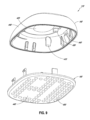
特定の実施形態では、各ウィングは接着剤を含み得る。実施形態において、電極は、接着剤と同じ平面内にあることができる。特定の実施形態において、各ウィングは、少なくとも1つのリム(rim)を含み、リムは、各ウィングの隣接部分よりも薄くなっている。ハウジングは、ハウジングと哺乳類の表面との間の空気の流れを可能にするように構成されたディンプル又は溝をさらに含んでもよい。特定の実施形態では、リムは、哺乳類の表面からのウィングの一部の解放を防止するように構成される。いくつかの実施形態では、生理学的システムをモニタリングするための電子装置は、少なくとも1つの軸における動作信号を検出するように構成された測定器を含んでいてもよい。この測定器は、3軸の動作信号を検出するように構成され得る加速度計であってもよい。 In certain embodiments, each wing may include adhesive. In embodiments, the electrodes can be in the same plane as the adhesive. In certain embodiments, each wing includes at least one rim, the rim being thinner than adjacent portions of each wing. The housing may further include dimples or grooves configured to allow air flow between the housing and the surface of the mammal. In certain embodiments, the rim is configured to prevent release of a portion of the wing from the mammal's surface. In some embodiments, an electronic device for monitoring a physiological system may include a meter configured to detect motion signals in at least one axis. The instrument may be an accelerometer that may be configured to detect motion signals in three axes.
実施形態において、動作信号は、生理学的信号と同時に収集され得る。特定の実施形態では、生理学的信号と動作信号とが一致すると、動作アーティファクトが識別される。さらなる実施形態は、プリント回路基板アセンブリに結合されたイベントトリガに関し得る。いくつかの実施形態では、イベントトリガ入力は、トリガが作動したときにプリント回路基板にかかる機械的ストレスを防止するようにハウジングによって支持され、その結果、記録された信号におけるアーティファクトの原因を減少させることができる。イベントトリガは、凹状または凸状で、イベントトリガの位置を容易に特定できるように、人間の指より大きくてもよい。特定の実施形態では、電極トレースは、哺乳類の動作の間の信号の歪みを最小化するように構成される。特定の実施形態において、ガスケットは、ハウジングに密封可能に取り付けるための手段として使用され得る。 In embodiments, the motion signal may be collected simultaneously with the physiological signal. In certain embodiments, motion artifacts are identified when the physiological signal and the motion signal match. A further embodiment may relate to an event trigger coupled to the printed circuit board assembly. In some embodiments, the event trigger input is supported by the housing to prevent mechanical stress on the printed circuit board when the trigger is actuated, thereby reducing sources of artifacts in the recorded signal. be able to. The event trigger may be concave or convex and larger than a human finger to facilitate locating the event trigger. In certain embodiments, the electrode traces are configured to minimize signal distortion during mammalian movement. In certain embodiments, a gasket can be used as a means for sealably attaching to the housing.
特定の実施形態では、哺乳動物における生理学的信号をモニタリングする方法は、哺乳動物に電子装置を取り付けるステップを含み得て、装置は、哺乳動物から生理学的信号を検出するように構成された少なくとも2つの電極と、二次信号を検出するように構成された少なくとも1つの測定器と、電極及びハウジングに接続された少なくとも2つの電極トレースとを備え、方法はまた、生理学的信号を二次信号と比較してアーティファクトを識別するステップも含み得る。 In certain embodiments, a method of monitoring a physiological signal in a mammal can include attaching an electronic device to the mammal, the device configured to detect a physiological signal from the mammal. at least one meter configured to detect a secondary signal; and at least two electrode traces connected to the electrode and the housing; A step of comparing and identifying artifacts may also be included.
特定の実施形態では、アーティファクトの識別は、生理学的信号の周波数スペクトラムと二次信号の周波数スペクトラムとの間の比較を含む。実施形態において、二次信号は、哺乳類の活動及び位置を導出するために使用され得る動作信号を含む。特定の実施形態では、二次信号は、3軸で収集される。ある実施形態では、三次信号も収集されてもよい。特定の実施形態では、二次信号は、電子装置と哺乳動物との間の接続に関する情報を含んでいる。いくつかの実施形態では、二次信号は、哺乳類が眠っているときに検出するために使用されてもよい。 In certain embodiments, the identification of artifacts includes a comparison between the frequency spectrum of the physiological signal and the frequency spectrum of the secondary signal. In embodiments, the secondary signals include motion signals that can be used to derive activity and position of the mammal. In certain embodiments, secondary signals are collected in three axes. In some embodiments, a tertiary signal may also be collected. In certain embodiments, the secondary signal contains information regarding the connection between the electronic device and the mammal. In some embodiments, secondary signals may be used to detect when the mammal is asleep.
いくつかの実施形態では、モジュール式生理学的モニタリング装置の一部を取り外して交換する方法は、生理学的データを収集するために、7日を超える期間にわたって上記の装置を哺乳類に適用するステップと、第1の組の生理学的信号を検出するために、装置を使用するステップと、装置を哺乳類の表面から取り外すステップと、装置から第1の部品を取り外すステップと、第1の部品を第2の生理学的モニタリング装置に組み込むステップと、を含んでもよく、第2の生理学的モニタリング装置は、第2の組の生理学的信号を検出するよう構成される。 In some embodiments, a method of removing and replacing portions of a modular physiological monitoring device comprises applying said device to a mammal for a period of more than 7 days to collect physiological data; using the device to detect a first set of physiological signals; removing the device from the surface of the mammal; removing the first component from the device; and b. incorporating into a physiological monitoring device, a second physiological monitoring device configured to detect the second set of physiological signals.
いくつかの実施形態では、第1の構成要素は、永久的接続を使用せずに他の装置構成要素に電気的に接続される。いくつかの実施形態では、装置は、バネ接続をさらに含んでもよい。特定の実施形態において、第1の構成要素は、損傷を防止するためにハウジングによって2回目の使用のために保存されてもよい。特定の実施形態では、第1の構成要素は、第1の構成要素が取り外されると第2の構成要素を再度固定することが可能な機構によって装置内に固定される。 In some embodiments, the first component is electrically connected to other device components without using permanent connections. In some embodiments, the device may further include a spring connection. In certain embodiments, the first component may be preserved for a second use by the housing to prevent damage. In certain embodiments, the first component is secured within the device by a mechanism capable of re-securing the second component once the first component is removed.
特定の実施形態は、消費者用ウェアラブル製品または医療機器製品のいずれかから得られるような心臓鼓動(heart beat)間隔(interval)の時系列データから心拍情報を推論するためのシステムに関してもよい。さらなる態様は、追加のデータソースを使用することによって、より堅牢な及び/又はタイムリーな方法で心拍情報を推論することを可能にするシステムの改良に関係する。この追加データには、ECGから得られる要約統計値または特定の信号特徴、加速度計から得られるユーザ活動時系列データ、ユーザ状態に関連する情報、または記録の日/時間に関連する情報が含まれる場合がある。 Certain embodiments may relate to systems for inferring heart beat information from time series data of heart beat intervals, such as those obtained from either consumer wearable products or medical device products. A further aspect relates to improvements to the system that allow heartbeat information to be inferred in a more robust and/or timely manner by using additional data sources. This additional data includes summary statistics or specific signal features from an ECG, user activity time series data from an accelerometer, information related to user status, or information related to the date/time of recording. Sometimes.
特定の実施形態では、ウェアラブル医療センサからの心電図信号データを選択的に送信するシステムは、下記のようなものを含み得て、ここでQRSとは、心室脱分極(depolarization)時のECG記録の3つのフィデューシャルポイントを指す。 In certain embodiments, a system for selectively transmitting electrocardiogram signal data from a wearable medical sensor can include: where QRS is an ECG recording during ventricular depolarization; It refers to three fiducial points.
a. ECGにおける各Rピーク位置のリアルタイム推定値を生成するQRS検出器を組み込んだウェアラブル医療センサ。 a. A wearable medical sensor incorporating a QRS detector that produces a real-time estimate of each R-peak location in the ECG.
b. 予め設定されたスケジュールに従い、センサからスマートフォンまたはインターネットに接続されたゲートウェイ機器に、オンセットタイムスタンプとともにR-R間隔の時系列を送信すること。 b. Sending the RR interval time series along with the onset time stamp from the sensor to a smartphone or Internet-connected gateway device according to a preset schedule.
c. スマートフォンまたはインターネットに接続されたゲートウェイ装置から、R-R間隔の時系列とオンセットタイムスタンプをサーバに送信すること。 c. Sending a time series of RR intervals and an onset time stamp to a server from a smartphone or a gateway device connected to the Internet.
d. R-R間隔の時系列データから、最も可能性の高いリズムとそのオンセット/オフセット時刻をサーバーサイドのアルゴリズムで推論すること。 d. A server-side algorithm to infer the most probable rhythm and its onset/offset times from RR interval time series data.
e. 与えられた基準に一致する推論されたリズムのみがフィルタリング後に保持されるように、特定のフィルタ基準に従って推論された心臓のリズムのリストをフィルタリングすること。 e. Filtering the list of inferred heart rhythms according to specific filter criteria such that only inferred rhythms matching given criteria are retained after filtering.
f. フィルタリング後に残った各リズムのオンセット/オフセット時刻を、サーバからスマートフォンまたはインターネットに接続されたゲートウェイ機器に送信すること。 f. Sending the remaining onset/offset times of each rhythm after filtering from the server to a smartphone or a gateway device connected to the Internet.
g. フィルタリング後に残った各リズムのオンセット/オフセット時刻を、スマートフォンまたはインターネットに接続されたゲートウェイ装置からウェアラブルセンサに送信すること。 g. Sending the remaining onset/offset time of each rhythm after filtering from a smartphone or a gateway device connected to the Internet to a wearable sensor.
h. 各オンセットオフセット時間ペアに対応する記録されたECGのセクションをセンサからスマートフォンまたはインターネット接続されたゲートウェイ機器に送信すること。 h. Sending the recorded ECG section corresponding to each onset offset time pair from the sensor to a smart phone or Internet-connected gateway device.
i. 各オンセットオフセット時間ペアに対応する記録されたECGのセクションをスマートフォンまたはインターネットに接続されたゲートウェイ装置からサーバに送信すること。 i. Sending a section of the recorded ECG corresponding to each onset offset time pair from a smart phone or Internet-connected gateway device to a server.
リズムフィルタ基準は、患者によるウェアラブルセンサの使用に先立って、医師又は他の医療専門家によって特定され得る。他の実施形態では、リズムフィルタ基準は動的であり、予め定義された規則に従ってシステムの使用中に更新されることができる。いくつかの実施形態では、これらの事前定義されたルールは、システムの使用中の以前の所見に基づくフィルタ基準の調整を記述することができる。いくつかの実施形態では、各推論されたリズムのオンセット時間及びオフセット時間は、各リズムの結果として生じる持続時間が所定の最大許容持続時間よりも短くなるように調整される場合がある。計算された信頼度尺度は、リズムフィルタ基準への入力となる場合がある。いくつかの実施形態では、システムは、R-R間隔の時系列データから心拍情報を推論することを含む。特定の実施形態では、心拍推論システムは、APIを介してアクセス可能なクラウドサービスとして実装される。 Rhythm filter criteria may be specified by a physician or other medical professional prior to use of the wearable sensor by a patient. In other embodiments, the rhythm filter criteria are dynamic and can be updated during use of the system according to predefined rules. In some embodiments, these predefined rules can describe adjustments to filter criteria based on previous observations during use of the system. In some embodiments, the onset and offset times of each inferred rhythm may be adjusted so that the resulting duration of each rhythm is shorter than a predetermined maximum allowable duration. The computed confidence measure may be input to the rhythm filter criteria. In some embodiments, the system includes inferring heart rate information from the RR interval time series data. In certain embodiments, the heartbeat inference system is implemented as a cloud service accessible via an API.
特定の実施形態では、心拍推論システムは、スタンドアロンアプリケーションに組み込むことができるソフトウェアライブラリを通じて提供される。R-R間隔値は、フォトプレチスモグラフィ信号から推定されるものであってもよい。 In certain embodiments, the heart rate inference system is provided through a software library that can be incorporated into standalone applications. The RR interval value may be estimated from the photoplethysmography signal.
心拍情報を推論する方法の特定の実施形態では、心拍推論システムは、心拍の各タイプについて信頼度スコアを計算し、本方法は、以下のステップを含む。 In a particular embodiment of the method for inferring heartbeat information, the heartbeat inference system calculates a confidence score for each type of heartbeat, the method includes the following steps.
a. 与えられたユーザのR-R間隔の時系列データの収集から推論される各心拍タイプの頻度と持続時間を計算するステップ。 a. Calculating the frequency and duration of each heartbeat type inferred from the collection of RR interval time series data for a given user.
b. 所定のユーザのR-R間隔の時系列のコレクション全体にわたるリズムの推論された頻度および持続時間に基づいて、各リズムタイプに対する信頼度統計値を推定するステップ。 b. estimating a confidence statistic for each rhythm type based on the inferred frequency and duration of the rhythm across a given user's collection of RR interval time series;
c. 推論された各リズムの信頼度統計値が所定の閾値を超えるかどうかを評価するステップ。 c. Evaluating whether the confidence statistic for each inferred rhythm exceeds a predetermined threshold.
d. 信頼度統計値が閾値を超える推論リズムについてのみ、通話ソフトウェアにリズム情報を返すステップ。 d. Returning rhythm information to the call software only for inferred rhythms whose confidence statistic exceeds a threshold.
特定の実施形態において、心拍推論システムは、下記のものの1つ以上を含む追加のデータソースを受け入れる。 In certain embodiments, the heart rate inference system accepts additional data sources including one or more of the following.
e. 加速度計によって測定されたユーザ活動時系列データ。 e. User activity time series data measured by an accelerometer.
f. 各R-R間隔の時系列記録の特定の日および時間に関する情報。 f. Information about the specific day and time of the chronological recording of each RR interval.
g. ユーザの年齢、性別、モニタリングの臨床的適応、既往症、投薬情報、病歴に関する情報。 g. Information about the user's age, gender, clinical indications for monitoring, pre-existing medical conditions, medication information, and medical history.
h. 所定期間内のECG信号サンプル値の平均値、中央値、標準偏差または合計などのECG信号の特徴および要約統計値。 h. ECG signal characteristics and summary statistics such as mean, median, standard deviation or sum of ECG signal sample values over a given time period.
i. 例えば、各鼓動または引き続きの時間期間において、心臓鼓動の品質を示すために測定装置によって提供される信頼度レーティング。 i. For example, a confidence rating provided by the measuring device to indicate the quality of the heart beat at each beat or subsequent time period.
j. 鼓動内の間隔測定。 j. Intrabeat interval measurement.
実施形態において、心電信号データをモニタリングするためのシステムは、以下のものを含む。 In embodiments, a system for monitoring electrocardiographic signal data includes the following.
ウェアラブル医療センサであって、哺乳動物からの心電信号を検出し、心電信号内のRピーク位置を推定するように構成されたウェアラブル医療センサ。 A wearable medical sensor configured to detect an electrocardiographic signal from a mammal and to estimate an R-peak position within the electrocardiographic signal.
ここで、ウェアラブル医療センサは、R-R間隔の時系列およびタイムスタンプを仲介装置に送信するように構成され、仲介装置は、R-R間隔の時系列およびタイムスタンプをサーバにさらに送信するように構成される。 wherein the wearable medical sensor is configured to transmit the time series of RR intervals and timestamps to the intermediary device, and the intermediary device further transmits the time series of RR intervals and timestamps to the server. configured to
ここで、サーバは、R-R間隔の時系列およびタイムスタンプから最も確率の高いリズムおよびそれらのオンセット/オフセット時間を推論するように構成され、サーバは、第1の基準に従って最も確率の高いリズムをフィルタして、フィルタリングされたデータセットに送るように構成されている。 Here, the server is configured to infer the most probable rhythms and their onset/offset times from the time series of RR intervals and timestamps, the server determining the most probable It is configured to filter the rhythms and send them to the filtered data set.
ここで、サーバは、フィルタリングされたデータセットを、仲介装置を介してウェアラブルセンサに送り返すように構成されている。そして、 Here, the server is configured to send the filtered data set back to the wearable sensor via an intermediary device. and,
ここで、センサは、フィルタリングされたイベントのそれぞれを囲む時間帯のフル解像度の心電信号をサーバに送信する。 Here, the sensor transmits to the server a full-resolution electrocardiographic signal for the time period surrounding each of the filtered events.
特定の実施形態では、心臓信号データをモニタリングするためのシステムは、ウェアラブルセンサと通信するように構成されたサーバを含み、
ウェアラブルセンサは、哺乳類からの心臓信号を検出し、心臓信号内のRピーク位置を推定するように構成され、
ウェアラブルセンサは、R-R間隔の時系列およびタイムスタンプをサーバに送信するように構成され、
サーバは、R-R間隔の時系列とタイムスタンプから最も確率の高いリズムとそのオンセット/オフセット時間を推論するように構成され、
サーバは、第1の基準に従って最も確率の高いリズムをフィルタリングして、フィルタリングデータセットに送るように構成され、
サーバは、フィルタリングデータの要約を送信するように構成されている。
In certain embodiments, a system for monitoring cardiac signal data includes a server configured to communicate with a wearable sensor;
a wearable sensor configured to detect a cardiac signal from the mammal and estimate an R-peak position within the cardiac signal;
The wearable sensor is configured to transmit a time series of RR intervals and timestamps to a server;
the server is configured to infer the most probable rhythm and its onset/offset times from the time series of RR intervals and timestamps;
the server is configured to filter the most probable rhythms according to the first criterion and send them to the filtered data set;
The server is configured to send a summary of filtered data.
特定の実施形態では、心臓信号データをモニタリングするためのサーバが、
ウェアラブルセンサと通信するように構成されたポータルを含み、
ウェアラブルセンサは、哺乳類からの心臓信号を検出し、心臓信号内のRピーク位置を推定するように構成され、
ウェアラブルセンサは、R-R間隔の時系列およびタイムスタンプを仲介装置に送信するように構成され、仲介装置はさらにR-R間隔の時系列およびタイムスタンプをサーバに送信するように構成され、
サーバはまた、
R-R間隔の時系列とタイムスタンプから最も確率の高いリズムとそのオンセット/オフセット時間を推論するように構成されたプロセッサを含み、
プロセッサは、第1の基準に従って最も確率の高いリズムをフィルタリングしてフィルタリングデータセットに送るように構成され、
サーバはフィルタリングデータセットの要約を送信するように構成される。
In certain embodiments, the server for monitoring cardiac signal data comprises:
including a portal configured to communicate with the wearable sensor;
a wearable sensor configured to detect a cardiac signal from the mammal and estimate an R-peak position within the cardiac signal;
the wearable sensor configured to transmit the time series of RR intervals and timestamps to the intermediary device, the intermediary device further configured to transmit the time series of RR intervals and timestamps to the server;
The server also
a processor configured to infer the most probable rhythm and its onset/offset times from the time series of RR intervals and timestamps;
the processor is configured to filter the most probable rhythms according to the first criterion into the filtered data set;
A server is configured to send a summary of the filtered data set.
実施形態では、コンピュータ実行可能命令をその中に格納した非一過性の記憶媒体であって、
コンピュータ実行可能命令は、1つ以上のコンピューティング装置を含むコンピューティングシステムによって読み取り可能であり、
コンピュータ実行可能命令は、コンピューティングシステムに動作を実行させるためにコンピューティングシステム上で実行可能であり、
コンピューティングシステムは、
通信リンクを介して、コンピューティングシステムによって、患者モニタリング装置によって生成された生理学的センサデータを受信するステップを含み、
生理学的センサデータは、第1の患者に関連し、
コンピューティングシステムはまた、
生理学的データにおいて1つまたは複数の所定の一連の状態を示す可能性が高い1つまたは複数のポイントがあるかどうかを判断するために、コンピューティングシステムによって、生理学的センサデータを分析するステップと、
生理学的データにおける1つまたは複数の点のうちの少なくとも1つが、1つまたは複数の所定の条件のうちの少なくとも1つを示す可能性が高いと決定した後、コンピューティングシステムによって、患者モニタリング装置に送信するための電子データパッケージを生成するステップと、を含み、
電子データパッケージは、生理学的センサデータにおける1つまたは複数の点のうちの少なくとも1つが、1つまたは複数の所定の条件のうちの少なくとも1つを示す可能性があるに関する場所データを含む。
In an embodiment, a non-transitory storage medium having computer-executable instructions stored therein, comprising:
the computer-executable instructions are readable by a computing system including one or more computing devices;
computer-executable instructions are executable on a computing system to cause the computing system to perform operations;
the computing system
receiving physiological sensor data generated by the patient monitoring device by the computing system via a communication link;
the physiological sensor data is associated with the first patient;
The computing system also
analyzing the physiological sensor data by a computing system to determine if there are one or more points in the physiological data that are likely to indicate one or more predetermined sets of conditions; ,
After determining that at least one of the one or more points in the physiological data is likely to exhibit at least one of the one or more predetermined conditions, the computing system causes the patient monitoring device generating an electronic data package for transmission to
The electronic data package includes location data relating to the likelihood that at least one of the one or more points in the physiological sensor data is indicative of at least one of the one or more predetermined conditions.
特定の実施形態において、生理学的センサデータは、記録された信号データから測定された間隔データのサンプリングを含んでよく、データサイズの間隔データのサンプリングは、記録された信号データより小さい。 In certain embodiments, physiological sensor data may include a sampling of measured interval data from recorded signal data, wherein the sampling of interval data of data size is smaller than the recorded signal data.
特定の実施形態において、哺乳動物における生理学的信号をモニタリングするためのシステムは、哺乳動物から心拍データを検出し記録するように構成された装着型接着剤式モニタを含み得て、
装着型接着剤式モニタは心拍データから特徴を抽出するように構成され、装着型接着剤式モニタは処理装置に特徴を送信するように構成され、処理装置は特徴を解析し、関心位置を特定して、関心位置を装着型接着剤式モニタに戻して送信するよう構成されている。
In certain embodiments, a system for monitoring physiological signals in a mammal can include a wearable adhesive monitor configured to detect and record heart rate data from the mammal,
The wearable adhesive monitor is configured to extract features from the heartbeat data, the wearable adhesive monitor is configured to transmit the features to a processing device, and the processing device analyzes the features and identifies locations of interest. and transmit the location of interest back to the wearable adhesive monitor.
特定の実施形態では、患者モニタリング装置からの生理学的センサデータを評価するシステムは、
コンピュータプロセッサと、第1のサーバに格納された命令セットを含むプログラムを提供するように構成されたコンピュータプロセッサと組み合わされた非一過性のコンピュータ可読媒体とを含み、
命令セットはコンピュータプロセッサによって実行可能であり、さらにプログラムのセンサデータ推論モジュールを実行するように構成され、
プログラムのセンサデータ推論モジュールは、命令を格納して、
患者モニタリング装置によって生成された生理学的センサデータを受信し、生理学的センサデータは第1の患者に関連し、
生理学的データにおいて1つまたは複数の所定の一連の状態を示している可能性が高い1つまたは複数のポイントがあるかどうかを判断するために、生理学的センサデータを分析し、
生理学的データにおける1つまたは複数の点のうちの少なくとも1つが、1つまたは複数の所定の条件のうちの少なくとも1つを示す可能性が高いと判断した後、患者モニタリング装置に送信するための電子データパッケージを生成し、
電子データパッケージは、生理学的センサデータにおける1つまたは複数の点のうちの少なくとも1つが、1つまたは複数の所定の条件のうちの少なくとも1つを示す可能性があることに関する場所データを含む。
In certain embodiments, a system for evaluating physiological sensor data from a patient monitoring device comprises:
a computer processor and a non-transitory computer readable medium in combination with the computer processor configured to provide a program comprising an instruction set stored on the first server;
the set of instructions executable by the computer processor and further configured to execute a sensor data inference module of the program;
The program's sensor data inference module stores instructions to
receiving physiological sensor data generated by a patient monitoring device, the physiological sensor data associated with a first patient;
analyzing physiological sensor data to determine if there are one or more points in the physiological data that are likely to indicate one or more predetermined sets of conditions;
for transmitting to a patient monitoring device after determining that at least one of the one or more points in the physiological data is likely to indicate at least one of the one or more predetermined conditions; generate an electronic data package,
The electronic data package includes location data relating to the likelihood that at least one of the one or more points in the physiological sensor data is indicative of at least one of the one or more predetermined conditions.
特定の実施形態において、コンピュータ化された方法は、
少なくとも1つのコンピュータ読み取り可能な記憶媒体からコンピュータ実行可能な命令にアクセスするステップと、
コンピュータ実行可能な命令を実行するステップと、を含み得て、
それによって、少なくとも1つのコンピュータプロセッサを含むコンピュータハードウェアに、
通信リンクを介してサーバコンピュータにより、患者モニタリング装置により生成された生理学的センサデータを受信するステップと、
生理学的データにおいて1つまたは複数の所定の条件を示す可能性が高い1つまたは複数のポイントがあるかどうかを判断するために、サーバコンピュータにより、生理学的センサデータを分析するステップと、
生理データの1つまたは複数の点のうちの少なくとも1つが、1つまたは複数の所定の条件のうちの少なくとも1つを示す可能性が高いと判断した後、サーバコンピュータによって、患者モニタリング装置に送信するための電子データパッケージを生成するステップと、を実行させ、
電子データパッケージは、1つまたは複数の所定の条件のうちの少なくとも1つが示される可能性が高いことを示す生理センサデータの1つまたは複数の点のうちの少なくとも1つに関する位置データを含む。
In certain embodiments, the computerized method comprises:
accessing computer-executable instructions from at least one computer-readable storage medium;
executing computer-executable instructions;
Thereby, in computer hardware, including at least one computer processor,
receiving physiological sensor data generated by a patient monitoring device by a server computer via a communication link;
analyzing the physiological sensor data by a server computer to determine whether there are one or more points in the physiological data that are likely to indicate one or more predetermined conditions;
transmitted by the server computer to the patient monitoring device after determining that at least one of the one or more points of the physiological data is likely to exhibit at least one of the one or more predetermined conditions; generating an electronic data package for
The electronic data package includes location data for at least one of the one or more points of the physiological sensor data indicating that at least one of the one or more predetermined conditions is likely to be exhibited.
本発明のこれらおよび他の態様および実施形態は、図面図を参照しながら、以下により詳細に説明される。 These and other aspects and embodiments of the invention are described in more detail below with reference to the drawing figures.
以下の説明は、多数の様々な実施形態に向けられる。しかしながら、記載された実施形態は、多くの異なる方法で実施および/または変化させることができる。例えば、記載された実施形態は、多数の生理学的パラメータのいずれかをモニタリングするための任意の適切なデバイス、装置、またはシステムにおいて実装され得る。例えば、以下の議論は、主に、長期的なパッチベースの心拍モニタリング装置に焦点を当てている。1つの代替実施形態では、生理学的モニタリング装置は、例えば、パルスオキシメトリ及び閉塞性睡眠時無呼吸症候群の診断のために使用され得る。生理学的モニタリング装置の使用方法もまた、様々であり得る。場合によっては、装置を1週間以下装着することもあるが、他の場合には、装置を少なくとも7日間及び/又は7日間以上、例えば14日間から21日間又はそれ以上の期間装着することもある。記載された技術の多くの他の代替的な実施形態及び応用が可能である。したがって、以下の説明は、例示的な目的のためにのみ提供される。本明細書を通じて、「コンフォーマル(適合した)」という用語が参照されることがある。本明細書で使用される用語「コンフォーマル」は、第1の表面または構造が第2の表面または構造の輪郭に適応する表面または構造間の関係を指すことが、当業者には理解されよう。 The following description is directed to a number of different embodiments. However, the described embodiments can be implemented and/or varied in many different ways. For example, the described embodiments may be implemented in any suitable device, apparatus, or system for monitoring any of a number of physiological parameters. For example, the discussion below focuses primarily on long-term patch-based heart rate monitoring devices. In one alternative embodiment, the physiological monitoring device can be used, for example, for pulse oximetry and obstructive sleep apnea diagnosis. The method of use of the physiological monitoring device can also vary. In some cases the device is worn for a week or less, in other cases the device is worn for at least 7 days and/or more than 7 days, such as 14 days to 21 days or more. . Many other alternative embodiments and applications of the described techniques are possible. Accordingly, the following description is provided for illustrative purposes only. Throughout this specification, reference may be made to the term "conformal." Those skilled in the art will appreciate that the term "conformal" as used herein refers to a relationship between surfaces or structures in which a first surface or structure conforms to the contours of a second surface or structure. .
異常な心臓のリズムまたは不整脈は、それほど深刻でない他の原因によることも多いため、これらの症状が不整脈によるものかどうかを判断することが重要な課題である。また、不整脈の発生頻度は低く、発作的であることが多いため、迅速かつ確実な診断が困難である。上述のように、現在、心拍モニタリングは、主にホルターモニタのような、胸部に貼付された短時間(1日未満)の電極を使用する装置の使用によって達成される。電極は、通常ベルトに装着された記録装置にワイヤで接続されている。電極は毎日交換する必要があり、配線は面倒である。また、記録装置のメモリや記録時間にも限りがある。装置の装着は患者の動きを妨げ、入浴などモニタリング中の特定の活動を妨げることが多い。さらに、ホルターモニタは資本設備であり、入手可能性が限られているため、しばしば供給上の制約やそれに伴う検査の遅れにつながる。このような制限は、装置の診断的有用性、装置を使用する患者の順応性(compliance)、およびすべての重要な情報を捕捉する可能性を著しく阻害するものである。順応性不足と機器の欠点は、正しい診断を行うために、追加の機器、フォローオンモニタリング、または他の検査の必要性につながることがよくある。 Since abnormal heart rhythms or arrhythmias are often due to other less serious causes, determining whether these symptoms are due to arrhythmias is an important issue. Moreover, since arrhythmia occurs infrequently and is often paroxysmal, rapid and reliable diagnosis is difficult. As noted above, heart rate monitoring is currently accomplished primarily through the use of devices such as Holter monitors that employ short-term (less than one day) electrodes applied to the chest. The electrodes are connected by wires to a recording device, usually worn on a belt. Electrodes have to be replaced every day, and wiring is troublesome. Also, the memory and recording time of the recording device are limited. Wearing the device impedes patient movement and often prevents certain activities during monitoring, such as bathing. Additionally, Holter monitors are capital equipment and have limited availability, often leading to supply constraints and consequent delays in testing. Such limitations severely hamper the diagnostic utility of the device, the compliance of the patient using the device, and the ability to capture all the important information. Poor compliance and equipment shortcomings often lead to the need for additional equipment, follow-on monitoring, or other tests to make a correct diagnosis.
ホルターモニタや心電計などの心拍モニタリング装置を用いて、症状と不整脈の発生を関連付ける現在の方法では、正確な診断を下すには十分でないことが多い。実際、ホルターモニタは90%まで診断につながらないことが示されている(DE Wardら著、「24時間外来心電図モニタリングの診断価値の評価」、Biotelemetry Patient Monitoring誌、第7巻、1980年出版)。 Current methods of correlating symptoms and arrhythmia occurrence using heart rate monitoring devices such as Holter monitors and electrocardiographs are often not sufficient to make an accurate diagnosis. In fact, Holter monitoring has been shown to be 90% non-diagnostic (DE Ward et al., "Assessment of the diagnostic value of 24-hour ambulatory electrocardiographic monitoring," Biotelemetry Patient Monitoring, Vol. 7, 1980).
さらに、実際に心拍モニタリング装置を入手してモニタリングを開始するという医療行為は、通常、非常に複雑である。通常、そのようなモニタリング装置からのデータの発注、追跡、モニタリング、回収、および分析には多数の手順が必要である。今日使用されている心臓モニタリング装置は、ほとんどの場合、患者の主治医(primary care physician:PCP)ではなく、心臓専門医または心臓電気生理学者(electrophysiologist:EP)によって発注される。このことは、PCPが患者を最初に診察し、患者の症状が不整脈によるものかもしれないと判断する最初の医師であることが多いため、重要な意味を持つ。患者がPCPを受診した後、PCPは患者に心臓専門医またはEPを受診させるための予約を取る。この予約は、通常、初診から数週間後に行われるため、診断が遅れ、不整脈のエピソードが発生しても診断されずに終わる可能性が高くなる。患者が最終的に心臓専門医またはEPにかかると、通常、心拍モニタリング装置が注文される。モニタリング期間は24~48時間(ホルターモニタ)または最長1カ月(心臓イベントモニタまたはモバイルテレメトリ装置)である。モニタリングが終了すると、患者は通常、装置をクリニックに返却しなければならず、それ自体が不便になることもある。データはモニタリング会社または病院やオフィスにいる技術者によって処理された後、最終的に報告書が心臓専門医またはEPに分析のために送られる。このようにプロセスが複雑なため、心拍モニタリングを受ける患者の数は、本来受けることが望ましい患者の数よりも少なくなってしまっている。 Furthermore, the medical practice of actually obtaining a heart rate monitoring device and initiating monitoring is typically very complicated. Ordering, tracking, monitoring, collecting, and analyzing data from such monitoring devices typically requires a number of procedures. Cardiac monitoring devices in use today are most often ordered by a cardiologist or electrophysiologist (EP) rather than a patient's primary care physician (PCP). This is significant because the PCP is often the first physician to see the patient and determine that the patient's symptoms may be due to an arrhythmia. After the patient sees the PCP, the PCP makes an appointment to see the patient with a cardiologist or EP. This appointment is usually made several weeks after the first visit, increasing the chances of delayed diagnosis and an undiagnosed episode of arrhythmia. When the patient finally sees a cardiologist or EP, a heart rate monitoring device is usually ordered. The monitoring period is 24-48 hours (holter monitor) or up to 1 month (cardiac event monitor or mobile telemetry device). Once monitoring is finished, the patient typically has to return the device to the clinic, which in itself can be inconvenient. After the data is processed by a monitoring company or a technician at the hospital or office, a final report is sent to a cardiologist or EP for analysis. This complexity of the process results in fewer patients receiving heart rate monitoring than would be desirable.
心臓モニタリングに関するこれらの問題のいくつかに対処するために、本願の譲受人は、小型で長期間着用可能な生理学的モニタリング装置の様々な実施形態を開発した。この装置の一実施形態は、Zio(登録商標)Patchである。様々な実施形態は、例えば、米国特許番号8,150,502、8,160,682、8,244,335、8,560,046、及び8,538,503、9,173,670、9,597,004、および米国特許公開番号第2018/0289274 Al号にも記載されており、これらの全開示内容は、その全体が参照により本明細書に組み込まれるものとする。一般に、上記文献に記載された生理学的パッチベースのモニタは、患者の胸部に快適にフィットし、少なくとも1週間、典型的には2~3週間装着されるように設計されている。モニタは、装置が装着されている間、連続的に心拍信号データを検出及び記録し、この心拍データは、その後、処理及び分析に利用可能である。 To address some of these issues with cardiac monitoring, the assignee of the present application has developed various embodiments of compact, long-wearable physiological monitoring devices. One embodiment of this device is the Zio® Patch. Various embodiments are disclosed, for example, in U.S. Pat. 597,004, and US Patent Publication No. 2018/0289274 Al, the entire disclosures of which are incorporated herein by reference in their entireties. In general, the physiological patch-based monitors described in the above references are designed to fit comfortably on the patient's chest and be worn for at least one week, typically two to three weeks. The monitor continuously detects and records heartbeat signal data while the device is worn, and this heartbeat data is then available for processing and analysis.
このような小型で長期間使用できるパッチ型生理学的モニタリング装置は、先行技術の装置と比較して多くの利点を提供する。同時に、さらなる改良が望まれている。最も有意義な改善点の1つは、管理する臨床医に重要な不整脈をよりタイムリーに通知することである。これらの初期の実施形態の特徴は、性能、順応性、およびコストの理由から、装置が長時間の装着期間中にのみ情報を記録し、解析および報告は記録が完了した後に行われることであった。そこで、収集したリズム情報をリアルタイムまたはタイムリーに解析する機能を追加することが望ましい改善点である。このようなタイムリーな報告機能を持つ診断モニタは現在存在するが、システムの1つ以上の電気部品を定期的に再充電または交換する必要がある。このような行為は、患者の順応性を低下させ、ひいては診断の歩留まりを低下させることにつながる。そのため、バッテリの充電や交換を必要とせず、長期間の記録とタイムリーな報告を両立できる生理学的モニタを開発することが重要な改善点となっている。 Such small, long-term patch-type physiological monitoring devices offer many advantages over prior art devices. At the same time, further improvements are desired. One of the most significant improvements is more timely notification of important arrhythmias to the managing clinician. A feature of these early embodiments, for performance, flexibility, and cost reasons, was that the device only recorded information during long periods of wear, with analysis and reporting occurring after recording was complete. Ta. Therefore, it is desirable to add a function to analyze the collected rhythm information in real time or in a timely manner. Diagnostic monitors with such timely reporting capabilities currently exist, but require periodic recharging or replacement of one or more electrical components of the system. Such actions reduce patient adaptability and, in turn, reduce diagnostic yield. Therefore, developing a physiologic monitor that does not require battery charging or replacement and that can achieve both long-term recording and timely reporting has become an important improvement.
患者の順応性と装置の接着性能は、ECG記録の持続時間、ひいては診断歩留まり結果を左右する2つの要素である。順応性は、患者の装着感を改善することで向上させることができ、装着感、装置の外観、装置が通常の日常生活動作にどの程度支障をきたすかなどに影響される。ECG記録が長いほど診断に役立ち、価値が高まるため、装置の接着と患者の順応性を改善することが望まれる。 Patient compliance and device adhesion performance are two factors that influence the duration of ECG recordings and thus the diagnostic yield results. Adaptability can be improved by improving the patient's comfort and is influenced by the comfort of the patient, the appearance of the device, how much the device interferes with normal activities of daily living, and the like. Because longer ECG recordings are more diagnostic and valuable, improvements in device adhesion and patient compliance are desired.
信号の質は装着している間中重要であるが、患者が臨床的に重要な症状を示す部位を記録にマーキングする場合は、より重要になる可能性がある。記録へのマーキングは、装置の外面にあるトリガによって最も簡単に行うことができる。しかし、トリガは、電極を内蔵した皮膚接触型プラットフォームの一部である可能性があるため、患者がトリガを感じる際に、著しい動作アーティファクトが発生することがある。望ましい装置の改良は、動作アーティファクトを最小限に抑えて作動させることができる症状トリガであり得る。 Signal quality is important during wear, but can become more important when patients mark recordings where they exhibit clinically significant symptoms. Marking the record is most easily accomplished by a trigger on the exterior of the device. However, because the trigger may be part of a skin-contacting platform that contains electrodes, significant motion artifacts may occur when the patient feels the trigger. Desirable device improvements may be symptom triggers that can be operated with minimal motion artifacts.
さらに、装置の製造が簡単でコスト効率が良いことが望ましく、製造時のスケーラビリティや、プロセスの再現性による品質の向上が可能になる。製造が単純であることは、分解が容易であることにもつながり、プリント回路基板を効率的に回収して、品質管理された別の装置で再利用することが可能になる。この高価な部品を効率的に再利用することは、診断モニタのコストを下げるために重要である。 In addition, it is desirable for the device to be simple and cost effective to manufacture, allowing for scalability in manufacturing and improved quality through process reproducibility. The simplicity of manufacture also translates into ease of disassembly, allowing printed circuit boards to be efficiently recovered and reused in different quality controlled equipment. Efficient reuse of this expensive component is important to reduce the cost of diagnostic monitors.
しかし、より長時間、より低コストのソリューションが、心臓外来(ambulatory)モニタリングのポートフォリオに追加する価値がある臨床シナリオも存在する。このようなニーズに対する潜在的な解決策のヒントは、スマートウォッチやウェアラブルフィットネスバンドなど、様々な消費者向け健康・フィットネス製品に搭載されつつある連続心拍検知機能から見出すことができる。連続心拍数データは、ユーザの一般的なフィットネスレベルに関する情報を提供するために使用することができるが、このデータを使用して、ユーザの健康とウェルネスに関連する意味のある情報を提供することは、より困難かつ価値のあることである。例えば、連続心拍数データから潜在的な不整脈を検出することができれば、心拍数センシング機能を搭載した消費者向け機器が、心臓の異常を早期に発見するためのスクリーニングツールとして機能する可能性がある。このようなアプローチは、例えば心房細動のリスクがある心不全患者など、リスクのある集団に対して長期的で費用対効果の高いスクリーニング方法を提供する上で臨床的に価値があると考えられる。また、このモニタリングアプローチは、発作性心房細動の治療において、副作用を抑えながら治療薬の投与量を長期的に調整する際にも有用である可能性がある。不整脈の検出だけでなく、心拍情報を適切に分析することで、睡眠やストレスへの応用も期待される。 However, there are clinical scenarios where a longer duration, lower cost solution is a worthy addition to the cardiac ambulatory monitoring portfolio. A hint of a potential solution to this need can be found in continuous heart rate detection, which is being incorporated into various consumer health and fitness products such as smartwatches and wearable fitness bands. Although continuous heart rate data can be used to provide information about a user's general fitness level, this data should not be used to provide meaningful information related to the user's health and wellness. is more difficult and worthwhile. For example, if potential arrhythmias can be detected from continuous heart rate data, consumer devices with heart rate sensing capabilities could serve as screening tools for early detection of heart abnormalities. . Such an approach would have clinical value in providing a long-term, cost-effective screening method for at-risk populations, such as heart failure patients at risk for atrial fibrillation. This monitoring approach may also be useful in the treatment of paroxysmal atrial fibrillation for long-term adjustment of therapeutic drug doses while limiting side effects. In addition to detecting arrhythmia, it is also expected to be applied to sleep and stress by appropriately analyzing heartbeat information.
接着性パッチなどの生理学的装置を用いた長期的な外来モニタリングは、特にモニタリング期間中に観察された不整脈の発生と期間に関する情報をタイムリーに提供することができれば、多くの臨床応用が可能である。特に高齢化に伴う有病率という点では、心房細動を効率的に検出することが最も重要なモニタリングニーズである。このニーズは、症状を呈する患者だけでなく、この不整脈に関連する脳卒中リスクの上昇を考慮し、高齢、心臓病などの慢性疾患の存在、あるいは外科手術の発生などの要因でリスクのある個人の無症状心房細動を広く集団ベースでモニタリングする必要がある。後者の場合、周術期(perioperative)および術後のモニタリングは、不整脈予防を目的とした手術(例えば、MAZEアブレーション法、ハイブリッド内膜・外膜治療法、いずれも心房細動の治療)だけでなく、麻酔を伴う一般手術においても、臨床的に価値のあるものとなり得る。心房細動の外来モニタリングの目的は、ある時間帯に心房細動が発生したかどうかという単純な二者択一の問題に絞られる場合もある。例えば、アブレーション手術後の患者のモニタリングでは、通常、心房細動の発生が完全にないこととして定義される成功を確認することが求められる。同様に、脳卒中後の患者のモニタリングは、主に心房細動の存在を評価することに関心がある。 Long-term ambulatory monitoring using physiological devices such as adhesive patches has many clinical applications, especially if it can provide timely information on the occurrence and duration of arrhythmias observed during the monitoring period. be. Efficient detection of atrial fibrillation is the most important monitoring need, especially in terms of its prevalence with aging. This need takes into account the increased risk of stroke associated with this arrhythmia, not only in symptomatic patients, but also in individuals at risk due to factors such as advanced age, the presence of chronic conditions such as heart disease, or the occurrence of surgical procedures. There is a need for widespread population-based monitoring of asymptomatic atrial fibrillation. In the latter case, perioperative and postoperative monitoring are limited to surgery aimed at arrhythmia prevention (e.g., MAZE ablation, hybrid intimal-adventitial therapy, both for treatment of atrial fibrillation). It can also be of clinical value in general surgery involving anesthesia. The goal of ambulatory monitoring of atrial fibrillation may be reduced to a simple binary question of whether atrial fibrillation has occurred during a given time period. For example, patient monitoring after ablation surgery usually requires confirmation of success, defined as the complete absence of atrial fibrillation. Similarly, post-stroke patient monitoring is primarily of interest in assessing the presence of atrial fibrillation.
しかし、そのようなシナリオであっても、心房細動が発生した場合、その発生をよりよく特徴付けるために、1日の負担(1日あたり心房細動にある時間の割合%)やエピソードの持続時間(例えば、エピソード持続時間のヒストグラムとして、または6分などの特定の制限を超えているエピソードの割合として表現)を、絶対値または以前のベンチマークとの比較で評価することは臨床的に意味があるかもしれない(例えば、処置前のモニタリング結果であるベースラインを使用)。実際、毎日の心房細動の負担を測定し、心房細動のエピソード持続時間を評価し、睡眠中および起床中の心房細動の発生を検討し、患者の身体運動の程度に反応して心房細動の存在を評価することは、この不整脈に対する薬剤ベースの治療の有効性の評価を含む様々な臨床シナリオにおいて重要である。 However, even in such a scenario, if atrial fibrillation does occur, daily burden (percentage of time in atrial fibrillation per day) and duration of episodes should be evaluated to better characterize its occurrence. It is clinically meaningful to assess time (e.g., expressed as a histogram of episode duration or as percentage of episodes exceeding a certain limit such as 6 minutes) in absolute values or in comparison to previous benchmarks. There may be (eg, using baseline, pretreatment monitoring results). Indeed, we measure daily atrial fibrillation burden, assess episode duration of atrial fibrillation, examine the occurrence of atrial fibrillation during sleep and during waking, and examine atrial fibrillation in response to the degree of patient physical exertion. Assessing the presence of fibrillation is important in a variety of clinical scenarios, including evaluating the efficacy of drug-based therapies for this arrhythmia.
モニタリング期間中にこの情報をタイムリーに入手できれば、管理医師は、例えば、新規経口抗凝固薬(NOAC)の用量や頻度を調整することで、管理が最適化されるまで治療を反復的に滴定することが可能になる。この管理パラダイムのさらなる例として、患者が無症候性心房細動を通知されること、すなわち可聴または振動ベースの警告による機器からの直接通知、機器に接続されたアプリケーションからの通知、または管理臨床医からの電話、メール、テキストメッセージによる通信のいずれか、により、心房細動管理のための「ポケットに薬がある状態」を適時に適用することができるようになる。 If this information is available in a timely manner during the monitoring period, the managing physician may iteratively titrate therapy until management is optimized, for example by adjusting the dose or frequency of novel oral anticoagulants (NOACs). it becomes possible to A further example of this management paradigm is that the patient is notified of asymptomatic atrial fibrillation, i.e., by direct notification from the device via an audible or vibration-based alert, notification from an application connected to the device, or notification by the managing clinician. A phone call, email, or text message communication from .
臨床的に重要な不整脈、例えば無症状の第2度心ブロックや完全心ブロック、長時間の休止、高レートの上室頻拍、長時間の心室頻拍、心室細動が観察される状況では、タイムリーな管理及び/又は介入がテーマであることは確かに明白である。例えば、長時間の休止や完全な心ブロックが失神を引き起こすという臨床シナリオは、タイムリーで信頼できるモニタリング方法が利用できれば、リスクのある患者の院内モニタリングの必要性を低減、あるいはなくすことができる、特に重要なケースである。このテーマは、より微妙な形態の変化、例えば、薬物投与に伴うQT延長にも及び、これは心臓の安全性に重大な影響を与えることが示されている。このような延長を適時に認識することで、例えば、薬剤の安全性と有効性を評価する臨床試験を早期に 終了させたり、あるいは、観察された延長を除去する手段として投与量や頻度を調整することができる。 In the setting of clinically significant arrhythmias, e.g., asymptomatic second-degree or complete heart block, prolonged pauses, high-rate supraventricular tachycardia, prolonged ventricular tachycardia, ventricular fibrillation , timely management and/or intervention are certainly obvious themes. For example, clinical scenarios in which prolonged pauses or complete heart block cause syncope could reduce or eliminate the need for in-hospital monitoring of at-risk patients if timely and reliable monitoring methods were available. This is a particularly important case. This theme extends to more subtle morphological changes, such as QT prolongation associated with drug administration, which have been shown to have a significant impact on cardiac safety. Timely recognition of such prolongation may lead, for example, to early termination of clinical trials evaluating drug safety and efficacy, or adjustment of dose or frequency as a means of eliminating observed prolongation. can do.
生理学的モニタリング装置
図1A及び1Bを参照すると、生理学的モニタリング装置100の一実施形態の斜視図及び分解プロファイル図が提供される。図1Aに見られるように、生理学的モニタリング装置100は、水密で剛性のハウジング115と結合された可撓性本体110を含んでもよい。当業者によって理解されるように、本明細書および本明細書全体を通して説明されるようなハウジングは、剛性材料または可撓性材料から構築され得、それによって、ハウジングを、変形に抵抗するような剛性または力を受けて屈曲および/または変形するような軟質とする。可撓性本体110(「可撓性基板」または「可撓性構成体」と呼ばれることがある)は、典型的には、ハウジング115から横方向に延びる2つのウィング130、131と、それぞれがウィング130、131の1つに埋め込まれた2つの可撓性電極トレース(electrode trace)311、312と、を含む。各電極トレース311、312は、可撓性本体110の底面上で、可撓性電極(図1Aでは見えない)と結合される。電極は、モニタリング装置100が取り付けられている患者からの心臓のリズム信号を感知するように構成されている。電極トレース311、312は、次に、ハウジング115に収容された電子機器(図1Aでは見えない)にそれらの信号を送信する。剛性ハウジング115はまた、典型的には、1つ以上のバッテリなどの電源を含む。
Physiological Monitoring Device Referring to FIGS. 1A and 1B, perspective and exploded profile views of one embodiment of a
可撓性の電極および電極トレース311、312を含む非常に可撓性の本体110とハウジング115との組み合わせは、多くの利点を提供し得る。重要な利点は、高忠実度の信号捕捉である。非常にコンフォーマルな可撓性のウィング130、131、電極およびトレース311、312は、電極-皮膚インターフェースへの外部エネルギーの伝達を制限する。例えばハウジング115に運動が付与される場合、皮膚へのコンフォーマル接着のシステムは、その運動がモニタされた信号に影響を与える程度を制限する。可撓性電極トレース311、312は、一般に、被験者の皮膚とのコンフォーマル接触を提供するのに役立ち、電極350(電極350は図1では見えないが、後述の図6Aでは見える)が皮膚から剥離または浮き上がるのを防ぐのに役立ち、それによって、電極350への応力の伝達を最小化することによって強い動作アーティファクト除去およびより良い信号品質が得られる可能性がある。さらに、可撓性本体110は、患者による装置100の快適な装着を14日以上、取り外すことなく容易にする構成および種々の特徴を含む。本明細書に記載される実施形態において典型的には患者に付着しないハウジング115は、装置100の快適性に寄与する特徴を含む。ヒンジ部分132は、可撓性本体110の比較的薄く、さらに可撓性の高い部分である。それらは、可撓性本体110がハウジング115に接合される領域で自由に撓むことを可能にする。患者が動くと、ハウジング115が患者の皮膚から自由に浮き上がることができるので、この可撓性は快適性を高める。電極トレース311、312も、信号の歪みなしに患者の動きを可能にするために、非常に薄く、可撓性である。
The combination of highly
ここで図1Bを参照すると、生理学的モニタリング装置100の部分分解図が、剛性ハウジング115を構成する、及びハウジング115内に収容される構成部品をより詳細に示している。この実施形態では、ハウジング115は、下部ハウジング部材145と着脱可能に結合する上部ハウジング部材140を含む。上部ハウジング部材140と下部ハウジング部材145との間に挟まれるのは、上部ガスケット370、および下部ガスケット360(図1Bでは見えないが、上部ガスケット370のすぐ下)である。ガスケット370、360は、組み立てられたときにハウジング115を水密状態にするのに役立つ。モニタリング装置100の多数の構成要素は、上部ハウジング部材140と下部ハウジング部材145との間に収容され得る。例えば、一実施形態では、ハウジング115は、可撓性本体110の一部、プリント回路基板アセンブリ(PCBA)120、バッテリホルダ150、及び2つのバッテリ160を収容してもよい。プリント回路基板アセンブリ120は、電極トレース311、312及びバッテリ160に接触するようにハウジング115内に配置される。様々な実施形態において、1つ以上の追加の構成要素が、剛性ハウジング115内に含まれるか、または剛性ハウジング115に取り付けられてもよい。これらのオプションの構成要素のいくつかは、追加の図面図を参照して、以下でさらに説明される。
Referring now to FIG. 1B, a partially exploded view of
バッテリホルダ150は、様々な代替の実施形態によれば、(図示の実施形態のように)2つのバッテリ、1つのバッテリ、または2つ以上のバッテリを保持することができる。他の代替的な実施形態では、他の電源が使用されてもよい。図示の実施形態では、バッテリホルダ150は、バッテリ160をホルダ150内に保持するための複数の保持タブ153を含んでいる。さらに、バッテリホルダ150は、PCBA120の表面からバッテリ160の正しい間隔を確立し、スプリングフィンガ、及び/又は接点235及び236との適切な接触を保証するための複数のフット152を含む。スプリングフィンガ235及び236は、この実施形態では、バッテリ160をPCBA120にはんだ付けする代わりに使用される。代替の実施形態においてはんだ付けが使用され得るが、スプリングフィンガ235及び236の1つの利点は、それらの構成要素のいずれかを損傷することなく、バッテリ160がPCBA120及びホルダ150から取り外され、したがって両方の多重再使用を可能にすることである。はんだ接続を排除することはまた、モニタリング装置100の組み立て及び分解を単純化し、迅速化する。
いくつかの実施形態では、上部ハウジング部材140は、患者イベントトリガとして機能することができる。患者が心拍モニタリングのために生理学的モニタリング装置100を装着している場合、患者が自覚した任意の心臓イベントを装置100に登録できる(例えば、装置のメモリにログインする)ことは、典型的に有利である。例えば、患者が心臓不整脈のエピソードであると信じるものを感じた場合、患者は何らかの方法で装置100をトリガし、その結果、知覚されたイベントの記録を備えることができる。いくつかの実施形態では、患者による知覚されたイベントのトリガは、トリガされたイベントに関連するデータの送信を開始することができる。いくつかの実施形態では、知覚されたイベントのトリガは、単に、トリガされたイベントの位置を有する連続記録をマークすることができる。いくつかの実施形態では、関連するデータの送信と連続記録のマーキングの両方が発生する場合がある。後のある時点で、知覚されたイベント中の患者の記録された症状を、装置100によって記録された患者の実際の心臓のリズムと比較することができ、これは、患者の知覚されたイベントが実際の心臓イベントと相関しているかどうかを決定するのに役立つ可能性がある。しかしながら、現在入手可能なウェアラブル心拍モニタリング装置における患者イベントトリガに関する1つの問題は、特にモニタリング装置が通常衣服の下に着用されるため、小さなトリガを見つけること及び/又は作動させることが困難である場合があるということである。さらに、トリガボタンを押すことは、その瞬間に記録された心拍信号が、患者がトリガすることによって装置に引き起こされる動作によって変化するように、装置上の電子機器及び/又は電極に影響を与える可能性がある。例えば、トリガを押すと、その瞬間に記録された心拍信号が不整脈のように見えるように、電極の一方または両方に震動が伝わる可能性がある(実際の不整脈イベントが発生していなくても、不整脈のように見えることがある)。さらに、例えば睡眠中や本機の上に寝ているときなど、不注意でトリガが作動する可能性もある。
In some embodiments,
しかしながら、図1A及び1Bに示す実施形態では、ハウジング115は十分に剛性であり、可撓性本体110は十分に柔軟であるため、患者によってハウジング115に加えられる運動によって、電極によって感知される異常な信号がほとんど、あるいは全く生じないかもしれない。この実施形態では、上部ハウジング部材140の中央部分はわずかに凹んでおり、装置100を装着している患者によって押されると、この中央部分がわずかに凹んでPCBA120上のトリガ入力を引き起こす。ハウジング115の上面全体が患者イベントトリガとして機能するので、それがわずかに凹んでいるという事実と併せて、一般に、衣服の下でも、患者がトリガを見つけて押し下げることは非常に容易であろう。さらに、ボタンの凹状の性質は、不注意な作動からそれを保護するように低くなっていることを可能にする。したがって、本実施形態は、現在入手可能な心臓のリズムモニタの患者イベントトリガで遭遇する問題のいくつかを軽減することができる。図1A及び1Bに示される特徴のこれら及び他の態様は、以下でさらに詳細に説明される。
However, in the embodiment shown in FIGS. 1A and 1B,
ここで図2Aおよび図2Bの実施形態を参照すると、プリント回路基板アセンブリ120(またはPCBA)は、上面220、底面230、患者トリガ入力210およびバネ接点235、236、237を含み得る。プリント回路基板アセンブリ120は、導電性経路、トラックまたは電極トレース311、312を使用して電子部品を機械的に支持し、電気的に接続するために使用されてもよい。さらに、PCBA120の敏感な性質および剛性ハウジング115と機械的にインターフェースする要件のため、PCBA120が、ECG信号にノイズまたはアーティファクトを導入する可能性のある不要な偏向(deflection)を防止するのに十分な実質的に剛性であることは有益である。これは、力が剛性ハウジング115を通ってPCBA120に伝達される患者トリガ起動時に特に可能である。PCBAの剛性を確保する1つの方法は、いくつかの実施形態において、PCBAの厚さが特定の値より相対的に上であることを確保することである。例えば、少なくとも約0.08cmの厚さが望ましく、より好ましくは、少なくとも約0.17cmの厚さが望ましい。本願において、PCBA120は、プリント回路基板(PCB)、プリント配線基板(PWB)、エッチング配線基板、またはプリント回路アセンブリ(PCA)とも呼ばれ、またはそれらで代用され得る。いくつかの実施形態では、PCBA120に加えて、またはPCBA120に代えて、ワイヤラップまたは二地点接続(point-to-point)構造が使用され得る。PCBA120は、アナログ回路およびデジタル回路を含むことができる。
2A and 2B, printed circuit board assembly 120 (or PCBA) may include top surface 220,
患者トリガ入力210は、上述した上部ハウジング部材140などの患者トリガからの信号をPCBA120に伝達するように構成され得る。例えば、患者トリガ入力210は、患者トリガ(例えば、上部ハウジング部材部分140の上面)からの圧力に応答するPCBスイッチまたはボタンであってよい。様々な実施形態において、患者トリガ入力210は、表面実装スイッチ、触覚スイッチ、LED照明付き触覚スイッチなどであってもよい。いくつかの実施形態では、患者トリガ入力210はまた、LEDなどのインジケータを作動させることができる。特定の実施形態は、別個の装置上またはスマートフォンアプリとしてなど、遠隔に位置するトリガを含むことができる。
本明細書で説明する装置100のような小型の2電極生理学的モニタリング装置を用いて人間または動物被験者から心拍信号を収集する際の1つの重要な課題は、アーティファクトと臨床的に重要な信号とを識別しようとする際に、2電極しかないことが時として限られた視点を与えることである。例えば、左利きの患者が、小型の2電極生理学的モニタリング装置を左胸に装着したまま歯を磨くと、歯磨きによって、記録された信号が深刻な心臓不整脈である心室頻拍に非常に似て見えるような動作アーティファクトがしばしば発生することがある。この心配を軽減するために、リード(つまりベクトル)を追加するのが従来の方法であるが、これは通常、ホルターモニタのように、患者の胸部のさまざまな場所にワイヤを追加することによって行われる。このアプローチは、生理学的モニタリング装置100のような小型で着用可能な長期モニタとは整合しない。
One significant challenge in collecting heartbeat signals from human or animal subjects using a compact two-electrode physiological monitoring device such as the
上述の問題に対する代替的なアプローチは、信号識別を支援するために1つ以上の追加のデータチャネルを提供することである。いくつかの実施形態において、例えば、装置100は、パッチ動作(patch motion)を検出するためのデータチャネルを含むことができる。特定の実施形態では、加速度計または他の適切な装置は、単一軸測定値、または代替的に3軸すべての組み合わせの大きさの変化を単に分析することによって、パッチ動作を提供し得る。加速度計は、その周波数スペクトラムを記録されたECG信号の周波数スペクトラムとアルゴリズム的に比較できるように、十分なサンプリングレートで装置の動作を記録することができる。動作と記録された信号が一致する場合、その時間帯に記録された装置が臨床的な(例えば心臓の異常に起因する)ソースからのものではないことは明らかであり、したがって信号のその部分をアーティファクトとして確信を持ってマークすることができる。この技術は、前述の歯磨き動作の例において特に有用であり、動作の急速な周波数ならびに高振幅のアーティファクトが、心室頻拍のような潜在的に生命を脅かす不整脈の心拍数および形態とそれぞれ類似している場合である。本項及び明細書の他の箇所に記載された他の適切な装置も、動作情報を提供するために利用され得る。
An alternative approach to the above problem is to provide one or more additional data channels to aid in signal identification. In some embodiments, for example,
いくつかの実施形態では、このような分析に3軸すべての大きさを使用することで、活動の変化ではなく、位置のシフトによる値の急激な変化を目立たなくすることができる。他の実施形態では、歩行や走行に伴う上下動によってもたらされる特定のタイプのアーティファクトに焦点を当てるために、身体の長手軸に沿ったような特定の測定軸を使用することに利点がある場合がある。同様に、加速度計と組み合わせてジャイロスコープを使用することで、経験した動作の性質についてさらなる解像度が得られる可能性がある。加速度センサのみで全身の動作を十分に分析できる可能性があるが、腕の動作による回転運動などの特定の動作は十分に複雑で、加速度センサだけでは識別できない可能性がある。 In some embodiments, using magnitudes on all three axes in such an analysis can obscure abrupt changes in value due to shifts in position rather than changes in activity. In other embodiments, it may be advantageous to use a specific measurement axis, such as along the longitudinal axis of the body, to focus on specific types of artifacts introduced by vertical motion associated with walking or running. There is Similarly, the use of gyroscopes in combination with accelerometers may provide further resolution of the nature of the motion experienced. Although the accelerometer alone may be sufficient to analyze whole-body motion, certain motions, such as rotational motion due to arm motion, may be sufficiently complex to be discerned by the accelerometer alone.
動作アーティファクトの検出に加えて、人間の身体活動のダイナミックレンジに調整された加速度計は、記録中の患者の活動レベルを提供し、アルゴリズムによる真の不整脈の検出の精度を高めることもできる。装置100のシングルリードの制限を考えると、上室性頻拍のようなレート変化に加えて、あまり目立たない波(例えばP波)を観察する必要がある不整脈は、コンピュータ化されたアルゴリズムだけでなく、訓練を受けた人間の目でも、判断が困難である。この特殊な不整脈は、その発症が突然であることも特徴で、心拍数の上昇と同時に患者の活動レベルの急上昇が検出されれば、非病的な洞性頻拍と、より確実に識別できるかもしれない。大まかに述べると、活動量情報を臨床現場に提供することで、運動による不整脈とそうでない不整脈の識別が可能になると考えられる。動作アーティファクトの検出と同様に、特定の方向に最適化された1軸加速度センサの測定は、歩行やランニングなどの活動タイプをより具体的に判断するのに役立つかもしれない。この追加情報は、症状をより具体的に識別するのに役立ち、それによってその後の治療方針に好影響を与える可能性がある。
In addition to detecting motion artifacts, accelerometers tuned to the dynamic range of human physical activity can also provide the patient's activity level during recording and improve the accuracy of the algorithm's detection of true arrhythmias. Given the single-lead limitation of
特定の実施形態では、3軸を有する加速度計は、運動の大きさが提供できる以上の利点を付与することができる。被験者が急速に動いていない場合、3次元加速度計の測定値は、PCBA120の傾き、したがって、元の向きに対する身体の向きを近似することができる。元の身体の向きは、適切な位置決め及び身体への装置の適用に必要とされる直立又は仰臥位のいずれかであると仮定することができる。この情報は、心不全の症例に多い、周期的な振幅の変化が観察される心臓アルテルナン(alternans)など、鼓動ごとの形態変化として現れる特定の心臓疾患を除外するのに役立つ場合がある。同様のビートごとの形態変化は、電極ベクトルに対する心臓位置のシフトによる体位のシフト時に、健康な被験者において観察可能であり、例えば、直立位置からしゃがんだ位置までである。設計上、単一チャネル装置100は、形態における潜在的な病的シフトを容易に除外するための代替ECGチャネルを有していないが、体位のシフトとの相関は、これらの正常な変化を説明するのに役立ち、誤診による不必要な治療を避けることができるであろう。
In certain embodiments, an accelerometer with three axes can provide benefits beyond what the magnitude of motion can provide. If the subject is not moving rapidly, the 3D accelerometer measurements can approximate the tilt of the
他の実施形態では、加速度計は、体の向きや動作に基づいて、睡眠インジケータとして使用することもできる。臨床イベント(例えば、休止)を提示する場合、睡眠中に発生したイベントと覚醒時のイベントを明確に分離する方法で情報を提示できることは、診断上有益である。実際、ECG由来の呼吸数などの特定のアルゴリズムは、患者が比較的動かない状態のときにのみ実行する意味があり、呼吸による胸の動作によって生じる微妙な信号変調を観察することができる。呼吸数情報は、特定の患者集団における睡眠時無呼吸症候群の検出に必要な情報の1つのチャネルとして有用である。 In other embodiments, the accelerometer can also be used as a sleep indicator based on body orientation and motion. When presenting clinical events (eg, pauses), it is diagnostically beneficial to be able to present information in a manner that clearly separates events occurring during sleep from those occurring during wakefulness. In fact, certain algorithms, such as ECG-derived respiration rate, only make sense to run when the patient is relatively motionless, allowing observation of subtle signal modulations caused by chest movement due to respiration. Respiratory rate information is useful as one channel of information needed for the detection of sleep apnea in certain patient populations.
特定の実施形態では、加速度計はまた、失神などの自由落下を検出するために使用され得る。加速度計により、装置100は、患者トリガに依存することなく、失神(syncope)及び他の自由落下イベントをマークすることができる場合がある。いくつかの実施形態では、そのような自由落下イベントのトリガは、関連データの送信を開始することができる。このような重要なイベントのタイムリーな検出を可能にするために、そして同時に、装置100のような小型のウェアラブル装置のバッテリおよびメモリの制限を考慮すると、加速度計読み取りの取得は、バーストで行われ、潜在的自由落下などの興味深い情報のみが高いサンプリング率でメモリに書き込まれる場合がある。このイベントトリガの概念の拡張は、先に説明したボタンの代わりに、又はボタンと組み合わせて、装置100上の特定のタッピング動作を患者トリガとして使用することである。複数のタイプのタッピングシーケンスの使用及び検出は、患者が事後的にトリガログに症状及び期間を手動で記録することに依存する代わりに、患者が正確に何を感じていたのかについてより良い解決及び精度を提供することができる。そのような追加された解像度の例としては、連続したタップの数によって症状の深刻度を示すことが挙げられる。
In certain embodiments, accelerometers can also be used to detect free fall, such as fainting. The accelerometer may allow the
あるいは、他の実施形態において、光学センサは、装置の動作と患者の体の動作とを区別するために使用されてもよい。さらに、追加の実施形態では、装置は、ボタン又はトリガを必要としない場合がある。さらに多くの実施形態では、本明細書の本項または本明細書の他の箇所に記載された好適な装置も使用することができる。 Alternatively, in other embodiments, an optical sensor may be used to distinguish between motion of the device and motion of the patient's body. Moreover, in additional embodiments, the device may not require buttons or triggers. In addition, in many embodiments, suitable devices as described in this section of this specification or elsewhere in this specification can also be used.
生理学的モニタリング装置100に追加され得る別のオプションのデータチャネルは、装置100の屈曲及び/又は湾曲を検出するためのチャネルである。様々な実施形態において、例えば、装置100は、装置100自体の動作アーティファクトを検出するために、歪みゲージ、圧電センサまたは光学センサを含むことができ、したがって、動作アーティファクトと心拍データを区別するのを助ける。装置100のためのさらに別の任意のデータチャネルは、心拍数を検出するためのチャネルであってもよい。例えば、パルスオキシメータ、マイクロフォン又は聴診器は、心拍数情報を提供することができる。重複した心拍数データは、アーティファクトからのECG信号の識別を容易にすることができる。これは、上室性頻拍などの不整脈がアーティファクトによって中断され、そのエピソードが実際には複数の短いエピソードであったのか、1つの持続したエピソードであったのかを判断しなければならない場合に特に有効である。周囲の電気ノイズを検出するために、別のデータチャネルが含まれる場合がある。例えば、装置100は、電磁干渉を拾い上げるためのアンテナを含むことができる。電磁干渉の検出は、実際のECG信号からの電気ノイズの識別を容易にすることができる。上述のデータチャネルのいずれかは、将来のノイズ識別をサポートするために保存されるか、またはリアルタイムで臨床的妥当性の即時決定のために適用され得る。
Another optional data channel that may be added to
ここで図3Aおよび図3Bの実施形態を参照すると、可撓性本体110がより詳細に示されている。図3Aに示されるように、可撓性本体110は、ウィング130、131、各ウィング130、131の少なくとも一部の周りの薄い境界(border)133(または「縁」または「端」)、電極トレース311、312、および各ウィング130、131のハウジング115との接合部またはその近くのヒンジ部132(または「ショルダ」)を含み得る。また、図3 Aには、上部ガスケット370が示されており、この説明では可撓性本体110の一部とは見なされないが、可撓性本体110のハウジング115への取り付けを容易にするものである。
3A and 3B,
ヒンジ部分132は、比較的薄い、可撓性本体110のさらに可撓性の高い部分である。これらは、可撓性本体110がハウジング115に接合される領域で自由に撓むことを可能にする。患者が動くと、ハウジング115が患者の皮膚から自由に浮き上がることができるので、この可撓性は快適性を高める。電極トレース311、312も、信号の歪みなしに患者の動きを可能にするために、非常に薄く、柔軟である。境界133は、すぐ隣接する部分よりも薄い可撓性本体110の部分であり、可撓性本体110から患者の皮膚への滑らかな移行を提供し、したがって、縁の浮きや可撓性本体110下の汚れや破片の侵入を防止するものである。
図3Bにより詳細に示すように、可撓性本体110は、複数の層を含むことができる。先に述べたように、いくつかの実施形態では、上部ガスケット370及び下部ガスケット360は、この説明の目的のために可撓性本体110の一部とは見なされないが、説明の完全性のために示されている。しかしながら、この区別は、説明を容易にするためだけのものであり、説明された実施形態の範囲を限定するように解釈されるべきではない。可撓性本体110は、上部基板層300と、底部基板層330と、接着剤層340と、可撓性の電極350とを含み得る。上部および底部基板層300、330は、1つまたは複数の可撓性ポリマなどの、任意の適切な可撓性材料で作られることができる。適切な可撓性ポリマは、ポリウレタン、ポリエチレン、ポリエステル、ポリプロピレン、ナイロン、テフロンおよび炭素含浸ビニルを含むことができるが、これらに限定されない。基板層300、330の材料は、所望の特性に基づいて選択することができる。例えば、基板層300、330の材料は、可撓性、弾力性、耐久性、通気性、水分蒸散性、接着性、および/またはその類似物に基づいて選択されることがある。一実施形態では、例えば、上部基板層300はポリウレタン製であってもよく、底部基板層330はポリエチレンまたは代替的にポリエステル製であってもよい。他の実施形態では、基板層300、330は、同じ材料で作られてもよい。さらに別の実施形態では、基板層330は、さらに多くの通気性および水分蒸散を提供するために、接着剤層340の上の領域に複数の穿孔を含むことができる。様々な実施形態において、生理学的モニタリング装置100は、装着時間中に取り外すことなく、シャワー中、運動中などに装置100が装着された状態で、14~21日以上もの間、患者によって連続的に装着されることがある。したがって、使用される材料および基板層300、330の厚さおよび構成は、生理学的モニタリング装置100の機能に影響を与える。いくつかの実施形態では、基板層300、330の材料は、アーク放電を防止するための静電気放電(ESD)バリアとして機能する。
As shown in more detail in FIG. 3B,
典型的には、上下の基板層300、330は、一方または両方の層300、330上に置かれた接着剤を介して互いに取り付けられる。例えば、基板層300、330間の接着剤または接合物質は、アクリルベース、ゴムベース、またはシリコーンベースの接着剤であり得る。他の代替実施形態では、可撓性本体110は、2つ以上の可撓性材料の層を含むことができる。
Typically, the upper and lower substrate layers 300,330 are attached to each other via an adhesive placed on one or both layers 300,330. For example, the adhesive or bonding material between
材料の選択に加えて、基板層300、330の寸法、すなわち厚さ、長さおよび幅、は、可撓性本体110の所望の特性に基づいて選択され得る。例えば、様々な実施形態において、基板層300、330の厚さは、可撓性本体110に約0.1mmから約1.0mmの間の全体の厚さを与えるように選択されてもよい。様々な実施形態によれば、可撓性本体110はまた、約7cmから約15cmの間の長さと、約3cmから約6cmの間の幅を有することができる。一般に、可撓性本体110は、電極350の間に必要な量の分離を提供するのに十分な長さを有するであろう。例えば、一実施形態では、一方の電極350の中心から他方の電極350の中心までの距離は、少なくとも約6.0cm、より好ましくは少なくとも約8.5cmとすべきである。この分離距離は、用途に応じて、変化し得る。いくつかの実施形態では、基板層300、330は、すべて同じ厚さを有してもよい。あるいは、2つの基板層300、330は、異なる厚さを有していてもよい。
In addition to material selection, the dimensions of
上述のように、ヒンジ部分132は、可撓性本体110が皮膚に固着したまま、剛性ハウジング115が患者から離れるように持ち上げることを可能にする。ヒンジ部分132の機能性は、皮膚を伸縮させる可能性のある様々な活動を通して、装置が患者に付着したままであることを可能にする上で重要である。さらに、ヒンジ部分132は、装置を装着している間の快適性を著しく改善することを可能にする。一般に、ヒンジ部分132は、可撓性本体110に大きすぎる剥離力を生じさせることなく、剛性ハウジング115の十分なリフトを提供するのに十分な幅を有するであろう。例えば、様々な実施形態において、ヒンジ部分132の幅は、少なくとも約0.25cm、より好ましくは少なくとも約0.75cmとすべきである。
As described above,
さらに、可撓性本体110の形状またはフットプリントは、所望の特性に基づいて選択されることがある。図3Aに見られるように、ウィング130、131および境界133は、可撓性本体110に全体的に「ピーナッツ」形状を与える丸みを帯びた縁部を有することができる。しかしながら、ウィング130、131は、長方形、楕円、ループ、またはストリップなどの任意の数の異なる形状で形成することができる。図3Aおよび図3Bに示す実施形態では、フットプリント上部基板層300は、底部基板層330のフットプリントよりも大きく、上部基板層300の延長が境界133を形成する。したがって、境界133は、上部層300が作られるのと同じポリウレタン材料で作られる。境界133は、上部層300のみを含むため、各ウィング130、131の隣接部分よりも薄い。より薄く、適合性の高いリムおよび/または境界133は、ウィング130、131の隣接するわずかに厚い部分から患者の皮膚への移行を提供し、したがって、可撓性本体110の縁が皮膚から剥がれ上がるのを防ぐのに役立つので、患者に対する生理学的モニタリング装置100の固着を高めると考えられる。境界133はまた、可撓性本体110の下に汚れ及び他の破片が集まるのを防ぐのに役立ち、皮膚への付着を促進し、また可撓性本体110の美観を向上させるのに役立つかもしれない。いくつかの実施形態では、境界133は、少なくとも約3mm、6mm、9mm、12mm、または15mmの幅(例えば、境界133の外縁から境界133の内縁まで)を構成し得る。代替実施形態では、基板層300、330のフットプリントは同じであってもよく、その場合、境界133がなくなる。
Additionally, the shape or footprint of
図1A~3Bの図示された実施形態は、ハウジング115からほぼ反対方向に(例えば、互いに対して180度の角度で)延びる2つのウィング130、131のみを含むが、代替実施形態では他の構成が可能である。例えば、いくつかの実施形態では、ウィング130、131は、互いに対して非対称な向きで配置されてもよく、および/または1つまたは複数の追加のウィングが含まれてもよい。生理学的信号モニタリングを可能にするために十分な電極間隔が提供され、ウィング130、131が皮膚への拡張された取り付けを提供するように構成される限り、任意の適切な構成および数のウィング130、131および電極トレース311、312が使用されてよい。上述した実施形態は、付着性、患者の快適性、及び収集された心臓のリズムデータの精度に有利であることが証明されているが、代替実施形態においては、代替構成を実施することが可能であり得る。
Although the illustrated embodiment of FIGS. 1A-3B includes only two
接着剤層340は、底部基板層330の底面の2つの部分に塗布される接着剤であり、それぞれの部分はウィング130、131の1つに対応する。したがって、接着剤層340は、ハウジング115が取り付けられる底部基板層330の部分に沿って延びることはない。接着剤層340は、任意の適切な接着剤で作られてもよいが、特定の接着剤が、比較的快適で皮膚刺激のない患者の皮膚への長期的な接着を提供するために有利であることが分かってきた。例えば、一実施形態では、接着剤層340はハイドロコロイド接着剤である。別の実施形態では、接着剤層340は、発汗時に皮膚から水分を取り込む天然由来または合成吸収性材料を含むハイドロコロイド接着剤を含む。
The
次に図3Bを参照すると、接着剤層340の2つの部分の各々は、電極350の1つが嵌まる穴を含む。電極350は、可撓性本体110の全体的な適合性をさらに提供するために、可撓性材料で作られる。一実施形態では、例えば、可撓性電極350は、ハイドロジェルで作られてもよい。電極350は、一般に、皮膚との電気的接続を強化し、動作アーティファクトを低減するために、皮膚とコンフォーマルで非刺激性の接触を提供する。いくつかの実施形態では、ハイドロジェル電極350は、接着剤層340に打ち抜かれ、こうして穴を形成し、ハイドロジェル電極350で埋めることができる。1つの代替実施形態では、電極350および接着剤340は、各ウィング130、131の下側の接着剤層全体が電極として機能するように、導電性材料でできた接着剤層で置換されてもよい。このような接着剤層は、ハイブリッド接着剤/導電性物質または導電性要素もしくは粒子と混合された接着性物質を含むことができる。例えば、一実施形態では、そのような接着剤層は、ハイドロジェルとハイドロコロイド接着剤とのハイブリッドであってもよい。図1Aのハウジング115はまた、ハウジングおよび/またはPCB A 120に含まれる電子機器および電源を保護し、知覚された心臓のイベントに関連する入力を提供する患者の能力を高め、ハウジング115の内容の少なくとも一部の簡単な製造および再利用可能性を可能にする。生理学的モニタリング装置100のこれらおよび他の特徴は、以下により詳細に説明される。
Referring now to FIG. 3B, each of the two portions of
上述したように、いくつかの実施形態では、接着剤層340は、可撓性本体110の底面の少なくとも一部が接着剤層340を含まないように、底部基板層330の底面の一部を覆うことがある。図3Aに見られるように、ヒンジ部132は、接着剤層340が塗布されていない各ウィング130、131の部分として、可撓性本体110に形成されてもよい。ヒンジ部分132は、一般に、可撓性本体110とハウジング115との接合部又はその近傍に位置し、したがって、患者の動作に対応するために装置100の柔軟性を提供する。いくつかの実施形態では、ヒンジ部分132は、ウィング130、131の隣接部分の幅よりも小さい幅を有することができ、したがって、装置100に上述の「ピーナッツ」形状を与える。図8に示すように、被験者が動くと、患者の動作に合わせて装置100が撓む。装置の屈曲は激しい場合があり、長期モニタリング中に何度も発生すると考えられる。ヒンジ部132は、被験者に対する動的適合性を可能にすることができ、一方、ハウジング115の剛性は、装置の屈曲中にハウジング115が患者の皮膚から飛び出すことを可能にし、したがって、装置100がその端部で皮膚から剥がれるのを防止し得る。
As noted above, in some embodiments,
可撓性本体110は、上部基板層300と底部基板層330との間に挟まれた2つの電極トレース311、312をさらに含む。各電極トレース311、312は、電極インターフェース部分310と心電図回路インターフェース部分313を含むことができる。図3Cおよび図3Dの実施形態に示されるように、ECG回路インターフェース部分313は、装置100または拡大装置部分101が組み立てられたときに、スプリングフィンガ237と物理的に接触し、PCBA120との電気通信を行う。電極インターフェース部分310は、ハイドロジェル電極350に接触する。したがって、電極トレース311、312は、電極350からPCBA120に心拍信号(および/または様々な実施形態における他の生理学的データ)を伝送する。
電極トレース311、312の材料および厚さは、可撓性、耐久性および信号伝送の所望の組合せを提供するために重要である。例えば、一実施形態では、電極トレース311、312は、銀(Ag)および塩化銀(AgCl)の組合せを含むことができる。銀および塩化銀は、層状に配置されてもよい。例えば、電極トレース311、312の一実施形態は、銀の最上層、炭素含浸ビニルの中間層、および塩化銀の最底層(患者に面する)層を含むことができる。別の実施形態では、電極トレース311、312の上部および底部の両方の層は、塩化銀で作られてもよい。一実施形態では、上部層及び底部層は、それぞれ銀インク及び塩化銀インクの形態で中間層に塗布されてもよい。代替実施形態では、各電極トレースは、銀の最上層および塩化銀の最底層など、2つの層のみを含んでもよい。様々な実施形態において、AgClなどの各電極トレース311、312の底部層の材料は、ハイドロジェル電極350の化学特性に適合し、被験者の身体とのハーフセル(half-cell)を作成するように選択され得る。
The material and thickness of electrode traces 311, 312 are important to provide the desired combination of flexibility, durability and signal transmission. For example, in one embodiment, electrode traces 311, 312 can include a combination of silver (Ag) and silver chloride (AgCl). Silver and silver chloride may be arranged in layers. For example, one embodiment of electrode traces 311, 312 may include a top layer of silver, a middle layer of carbon-impregnated vinyl, and a bottom (patient-facing) layer of silver chloride. In another embodiment, both the top and bottom layers of electrode traces 311, 312 may be made of silver chloride. In one embodiment, the top and bottom layers may be applied to the intermediate layer in the form of silver and silver chloride inks, respectively. In alternative embodiments, each electrode trace may include only two layers, such as a top layer of silver and a bottom layer of silver chloride. In various embodiments, the material of the bottom layer of each
電極トレース311、312の厚さは、多数の望ましい特性のうちのいずれかを最適化するように選択され得る。例えば、いくつかの実施形態では、電極トレース311、312の層の少なくとも1つは、時間の経過とともに陽極/陰極効果による材料の消耗を最小化または遅延するのに十分な厚さを有することができる。さらに、厚さは、所望の可撓性、耐久性、および/または信号伝送品質に対して選択され得る。 The thickness of electrode traces 311, 312 may be selected to optimize any of a number of desirable properties. For example, in some embodiments, at least one of the layers of electrode traces 311, 312 can have a thickness sufficient to minimize or retard material depletion due to anode/cathode effects over time. can. Additionally, the thickness may be selected for desired flexibility, durability, and/or signal transmission quality.
上述のように、いくつかの実施形態では、上部ガスケット370および底部ガスケット360は、可撓性本体110の上部基板300および底部基板330に取り付けられてもよい。ガスケット360、370は、ハウジング115の上部ハウジング部材140と下部ハウジング部材145との間に水密シールを提供する、ウレタンなどの任意の適切な材料で作られてもよい。一実施形態では、上部ガスケット370および/または下部ガスケット360は、接着面を含み得る。図3Eは、上部ガスケット370が、上部基板300に接着されたまま上部ハウジング部材140のプロファイルから離れて突出するタブ371を含むさらに別の実施形態を描写する。タブ371は、電極トレース311、312の一部を覆い、可撓性本体がハウジングと接する最も高い応力のポイントにおいて、トレースのための歪みリリーフを提供する。
As noted above, in some embodiments,
図4A~4Eは、図1~3の実施形態および図5A~8D以下の実施形態における接着剤層として含まれ得る接着剤層340の実施形態を示す。そのような接着剤層は、本明細書の本項または本明細書の他の箇所に記載された生理学的モニタリング装置の実施形態のいずれにでも組み込まれ得る。特定の実施形態では、接着剤層340は、図1A-B、3A-3E、および5A-8Dに描かれているような生理学的モニタリング装置の下の患者の皮膚の表面から、130、131として上述したような装置のウィングを通る水分の蒸散を最適化(例えば、最大化)するように構成され得る。生理学的モニタリング装置100を通る水分の蒸散を促進することは、(図3Eなどに示されるように)患者の皮膚と接着剤層340の底部との間の水分の収集または溜まりを防止、低減、および/または抑制することによって、患者の皮膚への装置100の接着を改善し得る。患者の皮膚と接着剤層340の底部との間の水分の収集は、特に長時間に渡って、接着剤層340の患者の皮膚への接着を防止、阻害、および/または妨害することがある。例えば、過剰な水分の存在は、患者の皮膚から離れた接着剤層340の縁部の剥離を引き起こし、促進し、および/または加速させる可能性がある。したがって、より長期間の接着は、大気中に放出(例えば、蒸発)され得るように、装置を通じた水分の蒸散を促進することによって達成され得る。水分の管理は、運動中や熱いシャワー中など、患者が汗をかく場合に特に有利になり得る。
Figures 4A-4E illustrate embodiments of an
特定の実施形態では、接着剤層340は、一般に、底部基板層330(図3Bなどに示すような)または別の支持層の底面に接着された上面と、患者の皮膚に接着されるように構成された底面を含む場合がある。上面は底面に概ね重なっていてもよく、および/または、接着剤層340の上面および底面は、水平面内で接着剤層340の周縁部まで延びる接着領域または表面領域を規定してもよい。接着剤層340は、底面から上面に延びる垂直方向の厚さを有していてもよい。厚さは、接着領域にわたって比較的均一であってもよい。いくつかの実施形態では、接着剤層340は、接着剤層340の底面を上面および/または接着剤層340の周縁に接続する複数のチャネル341を含んでいてもよい。チャネル341は、接着剤層340内の中空空隙として形成されてもよい。チャネル341が被験者の皮膚とインターフェースするチャネル341の累積表面積は、いくつかの実施形態において、水分蒸散速度に比例し得る。空隙領域の累積表面積が大きいと、蒸散速度は増加するが、被験者の皮膚と接着剤層340との間の粘着力の量が減少する可能性がある。接着剤層340は、空隙容積を粘着マトリックス材料(例えば、ハイドロコロイド)から分離する障壁を含んでいてもよいし、含んでいなくてもよい。
In certain embodiments, the
いくつかの実施形態では、接着剤層340内のチャネル341の包含は、一般に、接着剤層340を対象(例えば、皮膚)の表面に対してより適合性にすることができる。例えば接着剤層340は、複数のチャネル341の存在により曲げ歪みをよりよく吸収することができ、これにより、特に非平坦な表面上および/または動的なコンフォメーション変化を経験すると予想される身体の一部において、被験者に対する生理学的モニタリング装置(本節または明細書全体を通して本明細書に記載されるような)の接着を促進または改善することができる。複数のチャネル341は、特定の筋肉の伸張および/または収縮に応答して、(図3Bなどに示されるように)可撓性本体110のカスタマイズされた動作または歪みを促進するように配置され得る。
In some embodiments, the inclusion of
図4A~4Eは、チャネル341の異なる配置を含む接着剤層340の例をさらに表示する。複数のチャネル341は、概して直線的および/または非直線的であってよい。いくつかの実施形態では、複数のチャネル341は、接着剤層340の上面から底面まで延びる垂直チャネル341を含むことができる。図4Aは、垂直チャネル341を含む接着剤層の一部の上面図を模式的に示している。垂直チャネル341は、接着剤層340の上面および/または下面に対して実質的に垂直な方向に延在していてもよい。垂直チャネル341の断面は、図4Aに示すように、概ね菱形、円形(例えば、円筒形チャネル)、楕円形、長方形、台形、五角形、六角形、他の多角形、または任意の他の適切な形状を有してよい。いくつかの実施形態では、特に垂直チャネル341が小さい間隔をあけて配置されている場合、残りの接着剤層340は、図4Aに示すように、格子構造の形態を取ることができる。垂直チャネル341の形状は、格子状の接着剤層340の機械的特性に影響を与える可能性がある。ダイヤモンド形状のチャネル341は、アコーディオン状の優先的な膨張および/または圧縮を可能にすることができる。例えば、図4Aに図示された接着剤層340は、接着剤層340から形成された格子状の支柱に平行な軸に沿うよりも、菱形の垂直チャネル341の角度を二等分するものに平行な軸に沿った張力および/または圧縮に対する抵抗が小さい場合がある。また、接着剤層340は、垂直チャネル341のより大きな角度を二等分するものに平行な軸に沿って、垂直チャネルのより小さな角度を二等分するものに平行な軸よりも、張力および/または圧縮に対する抵抗が小さい場合がある。
4A-4E further display examples of
いくつかの実施形態では、複数のチャネル341は、接着剤層340の上面および底面を接続するチャネル341の水平方向の行または列を含むことができる。行または列は、比較的均一な間隔で配置されてもよい。行または列は、接着剤層340の周縁部からおよび/または周縁部まで延びていてもよい。行または列は、接着剤層を薄いストリップ342に分割する接着剤層340の周縁上の別の点まで接着剤層を横切って延びることができる。図4Bは、列チャネル341を含む接着剤層340を概略的に示している。いくつかの実装では、チャネル341の行または列のいずれかを含む接着剤層340は、行または列が被験者の身長に平行に延びるように(例えば、被験者の頭から被験者の足までの方向に整列して)、被験者上に配向されるように構成され得る。チャネル341を完全に、または部分的にでも被験者の身長に整列することは、被験者(例えば、人間の被験者)が直立した(例えば、立った)位置にあるときに、接着剤層340の下からの水分の重力による排水を有利に促進し得る。チャネル341の方向は、直交する成分によって定義することができ、重力の効果は、身長に整列された成分の大きさに依存し得る。チャネル341を第1の方向に整列させる(例えば、被験者の高さに整列させる)ことは、第1の方向に直交する第2の方向に沿った(例えば、被験者の高さに横方向に整列させる)引張力及び/又は圧縮力を部分的に緩和することができる。いくつかの実施形態では、チャネル341は、最も大きな歪みを受けると予想される方向に対して横方向に整列するように配置されてもよい(例えば、チャネル341は、生理学的モニタリング装置100が上に配置される筋肉の伸長/収縮の方向に対して横方向に整列されてもよい)。チャネル341は、接着剤層340の寿命を向上させるために、歪みの一部を吸収することができる。チャネル341の存在および特に配置は、特に特定の方向に沿って、被験者の皮膚からの剥離に対する接着剤層340の耐性を機械的に改善し、生理学的モニタリング装置100のより長期の接着を促進し得る(図3Eおよび他の場所に示されるように)。
In some embodiments, the plurality of
いくつかの実施形態では、複数のチャネル341は、行と列の両方を含み得る。行および列は、接着剤層340を接着材料の小さなアイランド343に分割する格子網を形成するために、均一に間隔をあけて(例えば、互いに実質的に垂直に)配置されることがある。アイランド343は、長方形構成(例えば、垂直格子網)、ダイヤモンド構成、台形構成、五角形構成、六角形構成、他の多角形構成などを有することができる。図4Cおよび図4Dは、チャネル341の格子状ネットワークを含む接着剤層340の例を模式的に示している。様々な実施形態において、チャネル341の間に最大分離距離344が存在し得る。言い換えれば、各チャネル341は、チャネル341の長さに沿った任意の点において、別のチャネル341から、または接着剤層340の周縁から、最大分離距離344以下だけ分離されてもよい。いくつかの実施形態では、最大分離距離344は、約1mm、2mm、3mm、4mm、5mm、6mm、7mm、8mm、9mm、10mm、11mm、12mm、13mm、14mm、15mm、20mm、25mm、30mm、または30mmより大きい場合がある。実際の分離距離は、最大分離距離344に等しくてもよい。いくつかの好ましい実施形態では、分離距離は、約8mmであってもよい。チャネル341の密接な間隔(例えば、最大分離距離344内)は、接着剤層340の下からの水分の蒸散をより効率的に促進し、および/または被験者の皮膚からの接着剤層340の剥離を防止、抑制、またはその量を減少させることができる。
In some embodiments,
いくつかの実施形態では、接着材料のストリップ342および/またはアイランド343は、薄いウェビング345のネットワークによって相互接続されることがある。ウェビング345は、ストリップ342及び/又はアイランド343を一緒に結合する材料の細い、可撓性のストランドを含んでもよい。いくつかの実施形態では、ウェビング345は、ナイロン、綿、ポリエステル、および/または別の適切な材料を含み得る。いくつかの実施形態では、ウェビング345は、図4Bに概略的に示されるように、ストリップ342および/またはアイランド343を通って延在してもよい。例えば、いくつかの実施形態では、ストリップ342および/またはアイランド343は、ストランドがストリップ342および/またはアイランド343の内部容積を通って延びるように、ウェビング345のストランドの周りに形成されてもよい。いくつかの実施形態では、ウェビング345のネットワークは、図4Cおよび図4Dに示されるように、ストランドの列および行の概ね直角なネットワークを含んでもよい。いくつかの実施形態では、ウェビング345のネットワークは、図4Cに示されるように、チャネル341の行および列と実質的に同じ方法で配向されてよく、ここで、ストランドの行はチャネル341の行を挟み、ストランドの列はチャネル341の列を挟んでいる。いくつかの実施形態では、ウェビング345のネットワークは、ウェビング345のストランドの行および列がチャネル341の行および列から約45度オフセットしている図4Dに示すように、異なる態様で配向される場合がある。ウェビング345は、アイランド343を通って斜めに延びていてもよく、ウェビング345のストランドは、チャネル341内で互いに交差していてもよい。
In some embodiments, strips 342 and/or
いくつかの実施形態では、チャネル341は、放射状パターン(例えば、線形スポークパターン)で配置されてもよい。いくつかの実施形態では、チャネル341は、非直線状(例えば、リング状のチャネル341の同軸配置)であってもよい。例えば、チャネル341は、図4Eに模式的に示されるように、水平面内で螺旋状に放射状に配置されてもよい。チャネル341は、中心点346で合流してもよい。いくつかの実施形態では、中心点346は、接着剤層340の固体片であってもよい。いくつかの実施形態では、中心点346は、図4Eに示すように、空隙空間であってもよい。空隙空間は、実質的に円形であってもよい。いくつかの実施形態では、空隙空間は、接着剤層340の総表面積の少なくとも約5%、10%、15%、20%、25%、または30%を占めてもよい。
In some embodiments,
いくつかの実施形態では、接着材料のストリップ342および/またはアイランド343は、薄い裏打ち層に貼付されてもよい。例えば、いくつかの実施形態では、ストリップ342および/またはアイランド343は、底部基板層330の底面上に直接形成されてもよい。いくつかの実施形態では、接着剤層340は、可撓性本体110の底部基板層330に転写された後に接着剤層340から除去される除去可能な裏打ち層上に形成されてもよい。いくつかの実施形態では、接着剤層340は、いかなる裏打ち層も無く形成されてもよい(例えば、ウェビング345の周りに形成される)。いくつかの実施形態では、チャネル341は、接着剤層340の作製中に形成されてもよい。例えば、接着剤層340の接着剤マトリックスは、チャネル341の形状を付与するダイの周りに形成されてもよい。いくつかの実施形態では、チャネル341は、接着剤層340の作製後に形成されてもよい。例えば、作製後に接着剤層340を穿孔してもよいし、接着剤層340に垂直チャネル341を打ち抜いてもよい。いくつかの実施形態では、チューブ(例えば、毛細管)が接着剤層340に挿入され、接着剤層340を通る垂直チャネル341を形成することができる。いくつかの実施形態では、接着剤層の水平ストリップは、接着材料のストリップ342および/またはアイランド343を残して(例えば、切断によって)除去されてもよい。いくつかの実施形態では、接着剤層340の接着剤マトリックスは、裏打ち層または基板上に形成されてもよく、これは、接着剤層340を底部基板層330に接着する前に接着剤層340から任意に除去されてもよい(図3Bおよびその他の場所に示されるものなど)。いくつかの実施形態では、接着剤層340は、本明細書の他の箇所に記載されるように、織布または不織布ウェビング345のネットワークのストランドの周りに作製され得る。接着剤層が不織布ウェビングのストランドの周りに作製される例では、チャネルは、接着剤を通して分散されたランダムな空隙(楕円体など、任意の適切な形状を有してよい)として現れる場合がある。空洞やポケットがつながっているところでは、チャネルが形成されるが、直接つながっていない場合でも、その存在によって接着剤を通る空気の流れが改善されることがある。より固くない粘着剤層では、このアプローチにより、皮膚への適合性が向上する可能性がある。いくつかの実施形態では、ウェビング345のネットワークは、接着剤層が作製された後に接着剤層340に結合される(例えば、押し込まれる)場合がある。ウェビング345のネットワークは、接着剤層340をダイまたは裏打ち層から除去するのを助けるため、および/または接着剤層340を可撓性本体110の底部基板層330の上に位置付けるために有用であり得る。特定の実施形態では、接着剤層340は、蒸散のためのチャネルを含むことができる。そのようなチャネルは、連続的な壁を有していてもよいし、有していなくてもよい。特定の実施形態では、チャネルは、垂直、直交、または任意の適切な角度で配向されることができる。
In some embodiments, strips 342 and/or
いくつかの実施形態では、接着剤層340は、水分吸湿性(wicking)材料(例えば、水吸着材料)を含んでよく、および/または水分吸湿性材料の層に結合されてもよい。吸湿性材料は、吸湿性繊維のマトリックスを含んでもよい。水分吸湿性材料は、ウール、ナイロン、ポリエチレンテレフタレート(PET)、ポリテトラフルオロエチレン(PTFE)、膨張PTFE(ePTFE)、熱可塑性エラストマ(TPE)、および/または任意の他の適切な吸湿性材料を含むことができる。いくつかの実施形態では、水分吸湿性材料は、コアが水を保持し、水を外側/上方に移動させ、繊維の外側のシースが周囲の接着剤を水分から絶縁できるように、疎水性及び/又は親水性であってよい。水分吸湿性材料は、接着剤層340の上面上(例えば、接着剤層340と底部基板層330との間)に層として形成されてもよいし、毛細管として用いてもよい。水分吸湿性材料は、複数のチャネル341のうちの1つ以上を部分的または全体的に充填またはライニングするために使用されてもよい。いくつかの実施態様では、水分吸湿性材料の包含は、被写体の表面からチャネル341を通して、および/または、水蒸気透過性層を通してなど、接着剤層340および/または上部基板層への水分の引き込みを容易にし得る。特定の実施形態では、水分は、最上部の表面に移動し、任意で、水蒸気透過性層を介して、および/または蒸発のために粘着剤の外縁に移動することができる。水分吸湿性材料の包含は、湿気が接着剤層340の剥離を促進しそうな接着剤層340の底部と被験者の皮膚との間のインターフェースから離れた接着剤層340内に湿気を貯蔵することを可能にし得る。生理学的モニタリング装置100の接着剤層340または他の層内の水分の貯蔵は、被験者の表面からの水分が、それが発生するのと同じくらい迅速に装置100を通して蒸散(transpire)することができず、接着剤層340の底面と皮膚の間の水分の蓄積を防止または阻害する場合に有利となり得る。いくつかの実施形態では、材料に存在する吸湿性材及び/又は繊維は、湿気が接着剤から半径方向外側に引っ張られるように配向され得る。接着剤の外側領域または穿孔が存在する場所では、それらの繊維の表面積を最大化する水分溜めが作成され、内部から蓄積される水分の蒸発を可能にすることができる。
In some embodiments,
接着剤層340の周縁は、接着剤層340の周縁への材料の望ましくない付着を促進する可能性がある。特に、境界133を含む例では、可撓性本体110の一部が接着剤層340の周縁に付着するようになる可能性がある。例えば、境界133を形成する上部基板層300の底面が、接着剤層340の周縁に付着するようになる可能性がある。接着剤層340の周縁への可撓性本体110の基板層の付着は、可撓性本体110をその意図された構成から変形させ、および/または、装置100と皮膚との間の長期接着の期間を阻害または減少させ得る、可撓性本体110全体の適切な機械的構造および応力の配分を妨害し得る可能性がある。さらにまたは代替的に、汚れ、破片、または皮膚の隣接部分が接着剤層340の周縁に付着することがあり、これも長期的な接着を妨害する可能性がある。接着剤層340の周縁部への異物の付着は、被験者の皮膚と接着剤層340の底面との間の材料の接着の喪失を促進するか、またはそれにつながる可能性がある。接着剤層340の剥離は、接着剤層340の端部で開始する傾向がある場合がある。縁部が皮膚から剥離し始めると、周縁部に接着されている境界133または他の材料が、底面と皮膚との間の接着剤層340の下に挟まれるようになる可能性がある。例えば、境界133は、接着剤層340の下に折り込まれ始めるかもしれない。接着剤層340の底面と被験者の皮膚との間の材料の挟み込みは、接着剤層340に応力を加える可能性があり、および/または接着剤層340を変形させて、周縁部から剥離が核となって生成し始めるような、さらなる剥離につながる可能性がある。接着剤層340の底面と外部材料との間の接着は、材料を接着剤層340の下に引き込み続け、特に、材料が、被験者の皮膚が接着剤層340に対して経験するよりも接着剤層340に対して強い接着を経験する場合、「尺取虫効果」を生じさせることがある。
The perimeter of
いくつかの実施形態では、接着剤層340の周縁への付着は、接着剤層340の周縁をブロッキングライナの形態の非粘着性材料で裏打ちすることによって防止または抑制されることがある。特定の例では、周縁部への付着を防止または抑制するためにブロッキングライナを不使用とできるように、周辺に接着剤を塗布しないことが可能である。周縁部に接着剤が使用されない場合、接着剤はキャリアフィルムに印刷されてもよいが、周縁部には印刷されない。いくつかの実施形態では、非粘着性材料は、シリコーン(例えば、ポリジメチルシロキサン(PDMS))および/または他の任意の適切な材料を含んでもよい。非粘着ライニングは、接着剤層340の周縁部全体を覆ってもよいし、周縁部の連続部分および/または不連続部分を覆ってもよい。非粘着ライニングは、環状(例えば、リング状)の構成を含む場合がある。非粘着性ライニングの内径は、接着剤層340の外径と概ね等しくてもよい。非粘着ライナは、接着剤層340の周縁に適合し、かつ/または接着剤層340から剥離することなく被験者が動くときに動的歪みを経験し得るように、一般に可撓性または弾性であってもよい。非粘着ライニングは、周縁の上部から周縁の底部まで延在してもよいし、厚さの一部(例えば、上部、底部、および/または中間部)に沿って延在してもよい。非粘着性ライニングは、接着剤層340の周縁部からライニングの外縁部まで延びる幅を含んでいてもよい。幅は、約0.5mm、1mm、2mm、3mm、4mm、または5mmを超えない範囲であってよい。いくつかの実施形態では、非粘着ライナの内径は、粘着面を含んでいてもよく、これは、非粘着ライナの接着剤層340の周縁への接着を促進し得る。いくつかの実施形態では、非粘着性ライナの底面は、接着剤層340の底面と非粘着性ライナの外径との間に緩衝を作り出す非粘着性であってもよい。いくつかの実施形態では、非粘着性ライニングの底面は、粘着性であってよく、被験者の皮膚に付着するように構成される。非粘着性ライナは、可撓性本体110の任意の部分、任意の他の材料、または皮膚の隣接部分が接着剤層340の周縁に付着することを防止または抑制することができ、および/または材料が接着剤層340の底面と被験者の皮膚の間に挿入することを防止または抑制することができる。非粘着性ライナは、被験者の皮膚への接着剤層340の長期的な粘着の持続時間を促進または増加させ得る。
In some embodiments, adhesion of the
いくつかの実施形態では、接着剤層340の周辺領域は、テーパ状の厚さを含むことができる。接着剤層340の厚さは、中心位置から半径方向外側に接着剤層340の周縁部に向かって減少することがあり、および/またはその逆もまたあり得る。いくつかの実施形態では、中心位置は、幅が接着剤層340の半径全体にわたって可変であるように、接着剤層340の概ね中心点であってもよい。いくつかの実施形態では、接着剤層340の中央領域は均一な厚みからなり、周辺環状領域はテーパ状の厚みを含むことがあり、および/またはその逆もある。いくつかの実施形態、特に接着剤層340が概ね円形の表面領域を含む実施形態では、接着剤層340の厚さは、周方向において、または周縁から等距離に位置する点において均一であってよい。いくつかの実施形態では、接着剤層340の少なくとも最も外側の1mm、2mm、3mm、4mm、5mm、6mm、7mm、8mm、9mm、または10mmは、テーパ状の厚さを含むことができる。より緩やかなテーパは、より有利な力学を提供し、接着剤層340を通してより均一に応力を分配し得る。接着剤層340の周縁部の厚さは、接着剤層340の最大厚さ(例えば、中央部における)の約5%、10%、15%、20%、25%、30%、40%、または50%を超えないようにしてもよい。いくつかの実施形態では、厚さは、無視できる厚さの概ね尖った縁部までテーパダウンしてもよい。周縁部の減少した厚さは、可撓性本体110、任意の他の材料、または皮膚の隣接部分が接着剤層340の周縁部に付着することを防止または禁止することができ、および/または材料が接着剤層340の底面と被験者の皮膚の間にそれ自体を挿入することを防止または禁止することができる。テーパ状の周縁部は、接着剤層340の被験者の皮膚への長期的な接着の持続時間を促進または増加させ得る。
In some embodiments, the peripheral region of
図5A~5Hは、図1A~1Bおよび図6A~6Hなどの明細書の後の追加図に描かれた生理学的モニタリング装置と同様の、生理学的モニタリング装置200の別の実施形態を概略的に示している。図5Aは、様々な構成層の水平方向の配置を含む生理学的モニタリング装置200の底面図を概略的に描写している。生理学的モニタリング装置200は、電極350の間に延びる長手方向軸に関してそれぞれ非対称または対称であるウィング232、231を含んでよい。一方のウィング231、232は、長手方向軸の上方に偏って分布する本体を含み、他方のウィング231は、長手方向軸の下方に偏って分布する本体を含むことができる。ウィング231、232は、可撓性本体を、長手方向軸に直角で、患者トリガ216も含むハウジング215を通って延びる横軸について非対称にすることができる。特定の実施形態では、患者トリガは、総上部面積の約10~30%、例えば上部面積の約20%、又は総上部面積の約23%、たとえば約22.8%を、包含することができる。特定の実施形態では、患者トリガは、約20%以上、約30%以上、約40%以上、約50%以上、または約75%以上を包含することができる。特定の例では、患者トリガは、ハウジングの上面全体を包含することができる。ウィング231、232は、図5Aに示すように、縦軸及び横軸の両方について反転又は裏返しされた同一の形状を含む場合がある。可撓性本体の構成は、被験者の身長に対して電極を斜めに配置するのに特に適している場合がある(例えば、図9B~図9E)。
5A-5H schematically illustrate another embodiment of a
図3A~3E、図5A~5H、および本明細書に記載の任意の他の実施形態に示されるような様々な実施形態では、接着剤層340および電極350を支持する基板または支持層のうちの1つまたは複数が、1つまたは複数の層の厚さを介して配置された穿孔または開口部332を含み得る。開口部332は、1つまたは複数の層を通して通気性を提供し、開口部332を含む層または層群を通して接着剤層340の下方から水分の蒸散を促進することができる。開口部332の形状および/または配置は、格子状接着剤層340の機械的性質に影響を与え得る。開口部332は、可撓性本体110、310に構造的支持を与える比較的剛性の高い層に対して、ある程度の順応性または適合性を与えることができる。例えば、開口部332は、薄い層の曲げやすさを促進することができる。いくつかの実施形態では、開口部332は、図5Aに示されるように、円形であってもよい。いくつかの実施形態では、開口部は、図4に示される垂直チャネル341と同様の菱形であってもよい。実施形態では、開口部332は、矩形、正方形、楕円形、台形、五角形、六角形、多角形、または任意の他の適切な形状であってもよい。接着剤層340の垂直チャネル341と同様に、開口部332は、特に開口部332が近くに配置されている場合、穿孔層の少なくとも領域内に格子構造を作り出すことができる。穿孔層は、垂直チャネル341に関して本明細書の他の箇所で説明したのと同じ方法で、穿孔層の水平面内の様々な軸に沿った張力および/または圧縮に対する異方性抵抗を提供することができる。
In various embodiments, such as shown in FIGS. 3A-3E, FIGS. 5A-5H, and any other embodiments described herein, of the substrate or support layer supporting
いくつかの実施形態では、ウィング130、131は、ウィング130、131の周縁部に沿って構造的な支持部材(図示せず)を含んでいてもよい。構造的支持部材は、細いワイヤ状の構成を含む場合がある。構造的な補強部材は、上部基板層300または底部基板層330など、ウィング130、131の任意の層内またはその間に配置されてもよい。いくつかの実施形態では、構造的補強部材は、接着剤層340の外側および周囲の境界133に配置されてもよい。構造的補強部材は、接着剤層340が縁に沿って剥離、劣化、および/または分解し始めたとしても、ウィング130、131の一般的な形状(例えば、外形)を維持または保持し得る。構造的支持部材は、比較的剛性の高い金属またはプラスチックを含み得る。いくつかの実施形態では、構造的支持部材は、形状記憶材料(例えば、ニチノール)を含んでもよい。形状記憶構造支持部材の形状記憶特性は、ウィング130、131の永久変形に抵抗し、例えば、ウィングの皺、および/または境界133が接着剤層340の下に挟まれ込むことを防ぐのに役立つ場合がある。
In some embodiments, the wings 130,131 may include structural support members (not shown) along the perimeter of the wings 130,131. Structural support members may include fine wire-like formations. Structural reinforcement members may be disposed within or between any layers of
いくつかの実施形態では、支持層は、少なくとも2つの重なり合う材料層(例えば、最上部基板層300及び最底部基板層330)を含んでもよい。いくつかの実施形態では、可撓性本体110の最底部基板層(例えば、底部基板層330)および/または最上部基板層(例えば、上部基板層300)は、2つ以上の層を含んでもよい。様々な層は、ポリエチレンテレフタレート(PET)および/またはポリウレタン(PU)を含んでもよい。様々な実施形態において、PETを含む層は、可撓性本体に構造的支持を与えることができる。PETは、可撓性本体110の層全体に存在する最も剛性の高いまたは硬い材料であってもよい。構造的支持を提供する層は、隣接するより皺になりやすい(例えば、より剛性の低い)層の皺に対する抵抗も提供することができる。様々な実施形態において、ポリウレタンを含む層は、可撓性本体110、310に適合性及び/又は通気性のバリアを提供することができる。ポリウレタンは、可撓性本体110の層全体に存在する最も剛性の低い材料または少なくとも最も剛性の高くない材料であってもよい。ポリウレタンは、一般に、水が周囲環境を通して侵入し、接着剤層340と被験者の皮膚との間に浸透するのを防ぐ水に対するシールを作成することができる。バリア層は、被験者がシャワーを浴びることを可能にするために特に有利であり得る。シャワー対応の生理学的モニタリング装置を提供することは、ユーザの順応性を向上させ、及び/又は長期間の装着を促進又は増加させる可能性がある。ポリウレタン層は、特にポリウレタン層が比較的薄い場合、ポリウレタン層を通して蒸散が起こることを可能にする一般的に通気性であってもよい。いくつかの実施形態では、穿孔されたPET層が、接着剤層340とポリウレタン層との間に配置される場合がある。実施形態では、ポリウレタン層は、接着剤層340と穿孔されたPET層との間に位置決めされてもよい。いくつかの実施形態では、最底層の基板層330は、例えば、基板によって提供される格子またはメッシュ構造の周りに接着剤を形成することを可能にするスパンポリウレタンで、接着剤層と一体化されてもよい。
In some embodiments, the support layer may include at least two overlapping material layers (eg,
図5B~5Gは、図5Aに示される実施形態の様々な構成層の底面図を概略的に描写し、実施形態の非限定的な寸法(mm単位)の例を含む。ウィング231、232を形成する様々な層の全ては、本明細書の他の箇所に記載されるように、電極350を受けるように構成された重なった孔を含んでよい。図5Bは、可撓性本体の主構造を形成する支持層202(例えば、ポリウレタン)を図示している。図5Cは、図5Bに描かれた挿入部Aの拡大図を示す。図5Dは、図5Gに示されるように、接着剤240の延長を支持する「バタフライフラップ」203を形成するように構成された追加層を図示し、これは、塗布中に接着剤が折り返ってそれ自身に付着する可能性を制限する役割を果たし得る。バタフライフラップ層203は、ヒンジライン134の間に延在することができる。図5Eは、水分透過を許容しながらウィング231、232に構造的支持を与えるための開口332を含む穿孔層204(例えば、穿孔PET層)を示す。穿孔層204は、図示のように、ウィング231、232の間に連続的に延びていない場合がある。図5Fは、図5Eに描かれた挿入部Aの拡大図を示している。図5Gは、2つの接着剤層240を描写している。様々な層の比較によって示されるように、穿孔層204は、長手方向軸に沿って接着剤層240の全長にわたって延びていない場合がある。接着剤層240は、バタフライフラップ層203によって上面が支持され、底面が被験者の皮膚に接着されるが、支持層202の上にあるヒンジ部分に接着されないフラップ249を形成するヒンジライン134を越えてハウジング315に向かって内側に延在してもよい。特定の実施形態では、支持層202のヒンジ部分1001が、接着剤240の近位部分および接着剤240の遠位部分の両方によって被験者の皮膚に固定されるこの特徴は、(図5Bに示すように)着用中に接着剤にかかる応力を分散し、皮膚への接着剤の結合をより容易に弱めることができ、剥離力を最小化できる。図5Hは、生理学的モニタリング装置200の透視図を描いている。
5B-5G schematically depict bottom views of various constituent layers of the embodiment shown in FIG. 5A, including non-limiting example dimensions (in mm) of the embodiment. All of the various
様々な実施形態において、接着剤層(例えば、接着剤層340、240、または本明細書に記載の他の任意の接着剤層)は、交換可能であり得る。接着剤層340を交換すると、装置100を被験者の皮膚に接着する実質的な能力を失い始めた、または失った接着剤層340に、新鮮な接着剤層340が取って代わることができるので、生理学的モニタリング装置100の装着期間を延長することができる。接着剤層340を置き換えるために、接着剤層340の上面は、可撓性本体110の基板層の底面(例えば、底部基板層330の底面)から分離されることがある。生理学的モニタリング装置100は、被験者の身体から取り外され、その後、接着剤層340が可撓性本体110から分離されることがある。接着剤層340は、接着剤層340の内側の角(例えば、ハウジング115に最も近い角)から始めて、可撓性本体110から接着剤層340を剥がすことによって、最も簡単に除去することができる。接着剤層340の除去を容易にするために、専用の除去装置が提供されることがある。例えば、除去装置は、接着剤層340と可撓性本体110との間に挿入されるように構成された薄い平坦なブレードを含んでもよい。除去装置は、ブレードから延びるハンドルを含んでもよい。ハンドルは、ブレードが平坦面上に支持され得る可撓性本体と平行に配置され、ハンドルが平坦面の上に配置され保持され得るように、ブレードから斜めに延びていてもよい。例えば、除去ツールは、接着剤層340のコーナを可撓性本体110から分離するために使用されてもよく、その後、接着剤層340のコーナを使用して、接着剤層340の残りを可撓性本体110から引っ張るか剥がすために使用されてもよい。除去ツールまたは別個の除去ツールは、除去ツールが接着剤層340を可撓性本体110の基板層から引っ張るか剥がすために使用され得るように、接着剤層340が可撓性本体110の基板層から部分的に分離した後に把持する手段を含んでもよい。交換用接着剤層340は、生理学的モニタリング装置100の製造または組み立て中に元の接着剤層340が可撓性本体110の基板層に適用されるときと同じまたは同様の方法で可撓性本体110に適用され得る。例えば、接着剤層340は、接着剤層340の下面上の裏打ち層上に形成されてもよく、これは、接着剤層の上面が可撓性本体110に接着された後に除去することができる。いくつかの実施形態では、交換用接着剤層は、可撓性本体110上の特徴に対する容易かつ正確な位置決めを可能にするために、テンプレートまたはツールの使用を通じて可撓性本体110に適用されることができる。
In various embodiments, the adhesive layers (eg,
いくつかの実施形態では、接着剤層340は、複数の層を含み得る。特定の例では、接着不良を経験した場合、または他の適切な理由のために、ユーザは、生理学的モニタリング装置100を取り外し、皮膚と直接接触していた340の最底層を除去することができる。この除去された層は、340の表面全体であって、340の新鮮な接着剤層を下に露出させるかもしれないし、340の環状領域であって、接着剤の一部分のみで新鮮な層を露出させるかもしれないし、全体領域より小さい他の領域であるかもしれない。特定の実施形態では、「使用済み」接着剤の層は、接着剤340の表面にわたって分布するパターンの形状をとることがあり、その結果、その表面にわたって新鮮な接着剤と「使用済み」接着剤の分布した混合物が得られる。接着剤の交換と同様に、最も新しい皮膚接触層の一部または全部の除去による接着剤の更新は、着用期間を延長する効果を有する場合がある。このような実施形態における340の複数の層は、接着剤と剥離ライナの組み合わせによって構築することができ、剥離ライナは、上面では解放可能であるが底面ではより永久的に接着するようにシリコーン化することができ、またはその逆も可能である。シリコーン化は、本体への接着を維持する上で過度の課題を引き起こすことなく、意図的な層の除去を可能にするように調整することができる。さらに、特定の例では、層に組み込まれたプルタブの使用により、接着剤層の除去を可能にすることができる。さらに、除去は、剥離ライナがその下の層に接着するよりも「使用済み」接着剤に強く接着するツールを通して可能にすることもできる。実施形態では、接着剤は、格子状又はメッシュ状の基板内に組み込まれ、一体性を失うことなく接着剤の他の層からの分離を可能にすることができる。いくつかの実施形態では、生理学的モニタリング装置100は、ユーザの皮膚から取り外すことなく露出する接着剤の環状リングを有することができる。各ウィングの接着剤の内側形状は、環状リングが除去される間、接着されたままであり、新鮮な接着剤を露出させ、長時間の装着を可能にすることができる。接着不良は接着剤の最も外側の縁から始まることが多く、したがって、外側の層の環状リングのみをリフレッシュするこのアプローチは、データ収集の中断を最小限に抑え、またユーザが装置を着用し続ける可能性を高めながら、着用期間を延ばすのに役立つ可能性がある。
In some embodiments,
いくつかの実施形態では、引き紐(pull string)(図示せず)は、接着剤層340と底部基板層330との間に挟まれ、接着剤層340に埋め込まれ、または接着剤層340に部分的に埋め込まれ、接着剤層340と底部基板層330との間に部分的に挟まれ得る。引き紐は、接着剤層340の周縁を越えて延びる引き紐の近位に自由尾端を有することができる。引き紐は、特定のパターンに従って接着剤層340の表面積を横切って延びていてもよい。いくつかの実施形態では、引き紐は、接着剤層340の周縁に密接に沿うか、またはトレースすることができる。いくつかの実施形態では、引き紐は、電極(単数または複数)350の外径に密接に沿うことがある。いくつかの実施形態では、引き紐は、接着剤層340の表面領域の周りに実質的に閉じた回路を形成してもよい。例えば、遠位尾端は、近位自由尾端に近接して配置されることがある。遠位尾端は、近位自由尾端と同様に接着剤層340の周縁を越えて自由に延びてもよいし、接着剤層340の表面領域内に配置されてもよい。引き紐は、基板層330から、または接着剤層340内の別の層から、取り外し可能な接着剤層を取り除くのを助けるように構成され得る。引き紐の自由尾端を引く(例えば、引き紐の自由尾端を接着剤層340の底面を横切って引く)ことにより、引き紐が接着剤層340を切り裂く、および/または接着剤層340もしくはその一部を可撓性本体110の基板層から分離(例えば、リフトオフ)させる場合がある。いくつかの実施形態では、引き紐は、接着剤層340の周辺境界領域(例えば、環状領域)を接着剤層340の内側中央部分から取り除くことができる。接着剤層340の境界領域および/または他の部分は、底部基板層330または接着剤層340内の他の層から持ち上げられてもよい。接着剤層340の異なる部分の間に分割を形成することは、底部基板層330からの部分の除去を容易にし得る。引き紐によって接着剤層340に形成された新たな切断された縁は、底部基板層330から接着剤層340を剥離するための開始位置を提供することができる。これらの縁部は、特に自然の縁部が底部基板層330の縁部と同一平面上にある場合、接着剤層340の自然または元の周縁部から分離することがより容易であり得る。可撓性本体110の周縁部で2つの薄い縁を互いに分離するよりも、接着剤層の切断された縁を底部基板層330などの下地表面から持ち上げる方が簡単な場合がある。いくつかの実施形態では、引き紐を引くと、接着剤層340の切断された縁を底部基板層330の底面から少なくとも部分的に持ち上げ、接着剤層340のその後の剥離を容易にすることができる。いくつかの実施形態では、接着剤層340は、引き紐によって形成されない経路に沿って自然に区分されるか、または区分可能である場合がある。例えば、接着剤層340は、接着剤層340の表面領域にわたって穿孔の経路を配置することなどにより、引き紐と同様の外形に沿って特に分断可能であるように作製されてもよい。引き紐は、本明細書の他の箇所に開示された他の除去方法および/またはツールと組み合わせて使用することができる。
In some embodiments, a pull string (not shown) is sandwiched between the
いくつかの実施形態では、接着剤層340は、接着剤層340の上面が、底部基板層330の底面と同様に境界133の底面に接着されるように、基板層(例えば、上部基板層300を含む)の縁または境界まで完全に延びることがある。いくつかの実施形態では、可撓性本体110は境界133を構成せず、接着剤層は底部基板層330の端部まで延在していてもよい。交換可能な接着剤層340を含む実施形態は、可撓性本体110の外縁または境界まで延在する接着剤層340に特に適している場合がある。
In some embodiments,
図8A~8Jは、生理学的モニタリング装置400の実施形態を示す。いくつかの実施形態では、生理学的モニタリング装置400は、図8Aおよび8Bに示すように、電極トレース411、412に接続されるハウジング415を含んでよい。図8Aは、ハウジング415及びトレース411、412の側面図を示し、図8Bは、ハウジング415及びトレース411、412の上面図を示す。トレース411、412は、ハウジング415の側面から及び/又は底面から延びることができる。トレース411、412は、ハウジング415と反対側の端部で電極350に固定的に結合されてもよい。生理学的モニタリング装置400を組み立てるために、ハウジング415およびトレース411、412は、図8Cに示すように、可撓性本体410の底面に結合(例えば、接着)される場合がある。可撓性本体410は、概ね連続した平坦面を有する材料の単一ユニットであってもよい。可撓性本体410の外形または形状は、本明細書で説明する他の可撓性本体と同じであってもよく、図8Cおよび8Dに示すように一般に円形であってもよく、または任意の他の適切な形状であってもよい。いくつかの実施形態では、可撓性本体410は、電極350を受け入れるための開口部を含んでいてもよい。いくつかの実施形態では、電極は、可撓性本体410に内蔵されてもよい(例えば、電極は使い捨てであってもよい)。可撓性本体410は、接着剤層および境界層を含む、本明細書の他の箇所に記載されるような1つまたは複数の構成層を含んでもよい。構成層は、可撓性本体410の表面領域にわたって連続的に延びていてもよいし、離散的なサブエリアにわたって割合が決められていてもよい。連続的な可撓性本体410は、ハウジング415およびトレース411、412を覆う、モノリシックで連続的であってよい。特定の実施形態では、可撓性本体410は、トレース411、412を覆いつつ、ハウジング415のためのリリーフを可能にするように切断されてもよい。実施形態では、図8Cに示すように、連続的な可撓性本体410は、剛体本体および/またはハウジング415と、剛体本体および/またはハウジング415から延びるトレース411、412の長さの少なくとも一部とを囲む可撓性本体410の浮遊部分420またはバタフライフラップ部分周辺の経路に沿って切断されてもよく、電極は除かれてもよい。可撓性本体410は、ハウジング415を結合する前に、予めカットされた構成で提供されることがある。いくつかの実施形態では、可撓性本体410は、浮遊部分420を可撓性本体410の残部から容易に分離可能にするミシン目または他の壊れやすい特徴を含んでいてもよい。いくつかの実施形態では、可撓性本体410のプレカット領域は、皮膚から浮き上がるときにトレースを支持するヒンジ付き部分を含むことができる。浮遊部分420の底面は、図8Dに示すように、また本明細書の他の箇所に記載するように、浮遊部分420が被験者の皮膚から自由に持ち上がるように、接着剤を含まないことがある。特定の実施形態では、ヒンジ点の前のトレース411、412の遠位端の底面は、電極を皮膚によりよく固定するために接着剤で被覆されてもよい。
8A-8J show an embodiment of a
いくつかの実施形態では、ハウジング415は、図8E(プロファイル)および図8F(上面図)に示すように、感知電極350を含むことができる。図8Gに示すように、可撓性接着体410が、ハウジング415の上に配置されてもよい。いくつかの実施形態では、ハウジング415は、可撓性本体410に統合されたトレースへの電気的結合を可能にする電気接続部1003を外面上に含むことができる。このような配置は、トレースおよび電極を使い捨てにし、容易に交換することを可能にし得る。トレースとハウジングとの間の結合は、導電性接着剤、導電性接着剤、導電性ジェル、または他の適切な導電性材料によって可能になり得る。いくつかの実施形態では、上部保護層(図示せず)が、トレース411、412の上、および任意に、それらが可撓性本体410に結合された後の剛性本体410の上に設けられることがある。上部保護層は、可撓性本体410に結合(例えば、固着)されてもよい。上部保護層は、可撓性本体410と上部保護層の両方に重なり合うカットが課されるように、浮遊部分の可撓性本体410を切断する前に可撓性本体に結合されることがある。いくつかの実施形態では、上部保護層は、予め切断された形態で提供されてもよい。
In some embodiments,
生理学的モニタリング装置400の可撓性本体410は、交換可能であってもよい。可撓性本体410は、ハウジング415および電極トレース411、412から取り外されてもよく、交換用の可撓性本体410が、元のものが組み立てられたのと同じ方法で再装着されることがある。本明細書で議論される特定の実施形態では、可撓性本体410は、電極トレース411、412を含み、可撓性本体410は、同じ場所で別のものと交換するためにハウジング415から取り外されることがある。生理学的モニタリング装置400のこの実施形態は、接着剤層が摩耗および/または剥離し始めた後に生理学的モニタリング装置400の接着剤層を交換するための便利な方法を提供し、装置400の使用期間を長くすることを可能にし得る。
生理学的モニタリング装置
図6A~6Hは、図1A~5Hに描かれた生理学的モニタリング装置と同様の、生理学的モニタリング装置700の実施形態を描いている。図6Aは、生理学的モニタリング装置の透視図を描いている。図5Aと同様に、生理学的モニタリング装置700は、ウィングの下側に配置された電極を覆う電極インターフェース部分702の間にほぼ延びる長手軸に関して各々非対称であるウィング730、731を含んでよい。電極トレース704、は、電極と中央ハウジングとの間の電気通信を提供するために、ハウジングから電極に延びることができる。上記の図5Aのように、一方のウィング730は、長手方向軸の上方に偏って分布する本体を含み、他方のウィング731は、長手方向軸の下方に偏って分布する本体を含むことがある。したがって、ウィング730、731は、長手方向軸に垂直で、ハウジング706を通って延びる横軸について可撓性本体を非対称にすることができ、これは、本明細書本項または明細書の他の箇所に開示されている他の患者トリガと同様の患者トリガ707を含むことができる。本明細書の他の箇所に記載されているように、特定の実施形態では、患者トリガは、総上部面積の10~30%、例えば上部面積の約20%、または総上部面積の約23%、例えば約22.8%包含することができる。特定の実施形態では、患者トリガは、約20%以上、約30%以上、約40%以上、約50%以上、または約75%以上を包含することができる。特定の例では、患者トリガは、ハウジングの上面全体を包含することができる。ウィング730、731は、図6A~6Cに示されるように、縦軸と横軸の両方について反転されたまたは裏返しされた同一の形状を含むことができる。いくつかの実施形態では、ウィングは、サイズおよび形状が非対称であってもよく、例えば、上部ウィング730は、下部ウィング731よりも大きくてもよく、またはその逆でもよい。ウィング730、731の形状は、上部ウィング730の相対的な形状が、下部ウィング731の相対的な形状と異なるように、異なっていてもよい。特定の例では、上部ウィング730は、下部ウィング731またはその逆よりも大きな張力を受けることがあり、したがって、2つのウィングの間の異なるサイズおよび形状は、生理学的モニタリング装置の使用中に固有の力ベクトルに対処するのを助けることができる。ウィングの構成は、被験者の身長に対して電極を斜めに配置するのに特に適している場合があり、したがって、重力による剥離を潜在的に低減することができる。当業者であれば、ウィングの向きは、長手方向軸の上方または下方に偏って分布するのではなく、ウィングが鏡像化するように変更できることを理解するであろう。さらに、当業者であれば、本明細書に記載されるようなそのようなウィングの形状は、図5~6に描かれた一般的に丸みを帯びた形状とは異なっていてもよいことを理解するであろう。例えば、ウィングは、正方形状、長方形状、三角形状、五角形状、または任意の適切な多角形状のような、角ばった形状であってもよい。これらの多角形は、角からの剥離の可能性を低減するために、丸みを帯びた角を有することができる。本明細書の他の箇所に描かれているようなライナ708は、生理学的モニタリング装置を患者またはユーザに適用する前に、任意の接着剤を覆って保護するために使用され得る。実施形態では、ライナは、各ウィングの上に1つずつ、2つの部分に分離されることがある。
Physiological Monitoring Device FIGS. 6A-6H depict an embodiment of a
特定の実施形態では、追加の可視化パターン710がウィングを通って延びることがある。可視化パターン710は、電極トレースの輪郭を描き、ウィングの形状を縁取るための任意の適切なサイズまたは形状であってよく、例えば、可視化パターン710は、電極トレースの輪郭およびウィングの形状を反映するための丸みのある線などの線の形態であってよい。特定の実施形態では、1本、2本、3本、4本、またはそれ以上の線が存在することがある。いくつかの実施形態では、視覚化パターンは、そうでなければ透明な接着剤層が着用期間の経過を通じてユーザにとって視覚的に受け入れられなくなるにつれて(例えば、接着剤層が異物を拾い上げ、および/または湿気の吸収で曇る場合)、装置の視覚的清浄度が維持されるように、ドット、形状またはその他の組み合わせのパターンから形成されてもよい。特定の実施形態では、視覚化パターンは、例えば、時間の経過とともに色が変化したり、摩耗したりすることによって、ユーザに装置の装着期間を知らせるという別の機能目的を有することがある。この外観の変化は、適切なタイミングで装置を取り外すようにユーザに警告することができる。図6Bは生理学的装置700の実施形態の上面図を示し、図6Cは底面図を示し、図6D1は側面図を描いている。図6Cでは、可撓性電極712が見えている。図6D1に示すように、上部ハウジング714および底部ハウジング716の部分は、可撓性本体718の上方および下方に配置され得る。図6Eおよび図6Fは、生理学的モニタリング装置700の下側および上側を示し、すべての層が見えるように各層が透明である。各層は、生理学的モニタリング装置700の分解図において、より詳細に後述される。図5の実施形態で上に描かれた開口と同様の開口720は、接着剤層の上に位置する基板層に配置されることがある。より詳細に上述したように、このような開口部は、1つまたは複数の層を通して通気性を提供し、開口部を含む層または層群を通して接着剤層の下方から水分の蒸散を促進することができる。図6D2に示すように、実施形態では、ガスケット719は、ハウジングの1つ以上に共成形された上部ハウジングカバー714と下部ハウジング716の間に配置されてもよい。ガスケットは、接着剤アセンブリと隆起したインターフェース(図6D2の下に示される)または反対側のハウジング上の別のガスケットを圧縮して、内部電子機器ハードウェアに防水性を提供してもよい。図6B2に描かれているように、リッジ721が下部ハウジング716の上縁に配置されてもよく、リッジ721は接着剤層719に押し込むように構成される。当業者であれば、リッジ721は、例えば図721に描かれているような境界リッジのような、任意の適切な形状であってよいことを理解するであろう。いくつかの例では、リッジは丸みを帯びた、正方形、および/または多角形であってよい。特定の例では、リッジの高さは、約0.01mm~0.5mm、約0.05mm~0.4mm、約0.1mm~0.3mm、約0.1mm~0.2mm、または約0.13mmなどの約0.15mmであり得る。
In certain embodiments,
図6Gは、本明細書の本項および明細書の他の箇所に記載された生理学的モニタリング装置700の可撓性本体701の一実施形態の分解図を示す。ハウジング706は示されていない。当業者には理解されるであろうが、図6Gの画像は、皮膚上の位置決めに関連して逆さまに配向されている。図6G内の番号付けに従って、#7は、接着剤層(240/340)およびハイドロジェル電極(350)を保護する、剥離ライナを描写している。接着剤層の直上には、穿孔層204(本明細書に記載されるような開口部を含む)およびフラップ層203がある。特定の実施形態では、穿孔層およびフラップ層は、ポリエチレンテレフタレート(PET)および/またはポリウレタンなどの任意の適切な材料から構築され得る。穿孔層の直上には、ポリウレタンで構成されてもよい下部基板層#1が存在する。実施形態では、下部基板層は、少なくとも1つのテクスチャ面を有することができ、この面は、テクスチャ面がフラップ層#3に面するように配置されることができる。実施形態において、フラップ層#3はまた、少なくともテクスチャ加工された側を含むことができる。このテクスチャ加工された側面は、底部基板層#1に面するように構成されることがある。導電性電極トレースは、追加の別個の基板(311、312)上に印刷されてもよい。あるいは、いくつかの実施形態では、導電性電極トレースは、基板層#1上に直接印刷されてもよい。導電性電極トレースの上に位置するのは、上部基板層300であってもよい。上部基板層の上に位置するのは、追加のキャリア層#10であってもよく、次いで、接着剤層#11および最上部の硬質ライナ#9が続く。当業者であれば、このような層の配置は、図5H、図8A~8D、および図6A~6Fの実施形態など、本明細書に記載の生理学的モニタの任意の実施形態に適用可能であることを理解するであろう。
FIG. 6G shows an exploded view of one embodiment of
図6Hは、生理学的モニタ装置700のハウジング706の実施形態の分解図を示し、その中を、上で詳細に説明した可撓性本体701が通過している。上部ハウジングカバー714は、患者トリガ707を含むことができる。上部ハウジングカバーは、回路基板722を包囲してもよい。回路基板の下に配置されたスペーサ723は、回路基板の下側にある導電性接触ばねとバッテリ端子/ECGトレース接触との間の一貫した間隔を維持するように構成される。スペーサは、さらに、回路基板とバッテリとの間の電気絶縁を提供してもよい。スペーサには、導電性接触ばねを通すための穴があり、接触ばねは回路基板に接続される。バッテリ端子725は、可撓性本体701および回路基板722の下に配置されてもよく、それによってウェイブスプリング(波形バネ)726の上に重なる。実施形態では、バッテリ端子725は、コインバッテリ728の周りに巻き付けられ、付着させられてもよい。バッテリ端子725は、コインバッテリ728の正の下側をバッテリの負の上側まで持ってくることを可能にする導電性ビア727を有するフレックス回路として構成されてよく、これにより、負と正の両方の端子がバッテリの上側に提示されて回路基板の接触ばねに適合する。あるいは、底部ハウジングのバッテリ接点またはコンタクトは、コインバッテリの正の下側を負の上側に持ち上げて回路基板に接触させることを可能にし得る。通気層729は、下部ハウジングの通気孔732の上に、下部ハウジング部分716に対して配置され得る。実施形態では、通気層は、気体の通過を可能にしながら液体の通過を阻止する材料、例えばePTFEまたは任意の他の適切な材料を含んでもよい。通気層と組み合わせた通気孔732は、ハウジングの外側と内側との間の空気圧の正規化を可能にする。実施形態では、通気層と組み合わせた通気孔732は、例えば、患者が飛行機などの異なる高度にいる場合、外部の空気圧に応じてボタンおよび/またはトリガ707が膨れ上がったり吸い込まれたりすることを防止する。通気層は、底面にリング状の構成で接着剤を有する薄くて丸いものであってよい。通気層の接着剤で被覆された領域はガス透過性でない場合があり、中央部分はガス透過性であるが液体不透過性である場合がある。通気層の中央部分は、通気孔の上に配置することができ、それにより、液体の出入りを制限しつつ、ハウジングへのガスの出入りを可能にする。特定の実施形態では、通気層は、底部ハウジングに成形することによって一体化され得るが、底部ハウジングに超音波溶接され得るか、または任意の適切な手段を介して接着されることもできる。
FIG. 6H shows an exploded view of an embodiment of
図7A~7Bに示すように、いくつかの実施形態では、バタフライフラップ層203は、ハウジング115、706(上記図6Aおよび5Hにおいて)の直下に延在してもよい。バタフライフラップ層203の非粘着性の上面は、ハウジングがバタフライフラップに付着することを防止し得る。さらに、可撓性本体110の中央部分(例えばヒンジ部分132)は、被験者の皮膚の上、およびバタフライフラップ層203の上に浮くように構成されてもよい。図7Aは、可撓性本体110が被験者の皮膚から浮き上がるように構成されているヒンジライン134を間に有する可撓性本体110のプロファイルを模式的に示すものである。接着剤層340は、ヒンジライン134の外側で可撓性本体110の上にある基板層(例えば、底部基板層330)に付着され、ヒンジライン134の間でバタフライフラップ層203に付着され得る。図Aは、可撓性本体110の幅がハウジング115の直径を越えて延びる実施形態を示す。図7B~7Dは、可撓性本体110に結合され、ハウジング115の下に延びるように設計されたバタフライフラップ層203を含む接着剤層340の様々な構成例を模式的に示している。接着剤層340の形状(例えば、外形プロファイル)は、より長い着用期間を促進するために、被験者の皮膚からの接着剤層340の剥離を防止または抑制する方法で、接着剤層340にわたって力を機械的に分散するように構成され得る。接着剤層340の外縁は、特に接着剤層340の外縁がヒンジライン134と交差するところで、概して急角度を構成することができる。急な角度は、接着剤層340と被験者の皮膚との間の応力の複数の方向ベクトル、例えば剪断応力および引張応力を最大化する、および/または接着剤層340と被験者の皮膚との間の剥離応力を最小化する、接着剤層340を通る応力の分布を促進するように構成されることがある。剪断応力および引張応力は、皮膚からの接着剤層340の剥離を引き起こしにくくすることができる。応力を剥離しないベクトルにシフトさせることにより、長期的な接着性が改善され得る。
As shown in Figures 7A-7B, in some embodiments, the
例えば、図7Bは、一般に、誇張された蝶ネクタイ、パピヨン耳、および/または丸いダンベルに似たプロファイルを有する可撓性本体110を図示する。可撓性本体110は、ウィング130、131の一方の外縁から他方の外縁まで延び、2つのウィング130、131を対称的に二等分する長手軸を含んでいてもよい。可撓性本体110は、長手軸に垂直で、可撓性本体110(例えば、底部基板層330)を対称的に二分する横軸を有し、2つのウィング130、131を分離することができる。装置100の可撓性本体のヒンジ部分132は、2つのウィング130、131のヒンジライン134の間に延在してもよい。ヒンジ部分132は、接着剤層340を長手方向に対称的に二等分してもよい。ヒンジ部132は、2つのウィング130、131よりも横方向に狭くてもよい。ヒンジ部132は、底層の基板層(例えば、バタフライフラップ層203)よりも横方向に幅が狭くてもよい。可撓性本体110の外縁は、ヒンジライン134から長手方向軸および横方向軸に向かって内側に延びていてもよい。外縁は、外縁がヒンジライン134と交差するところで、湾曲した形状を有していてもよい。いくつかの実施形態では、外側縁部はそれぞれ、外側縁部が凸型曲率から凹型曲率に移行する変曲点(inflection point)を含んでいてもよい。凹状の曲率は、凸状の曲率よりも横軸に近い位置に配置されてもよい。変曲点は、ヒンジライン134上、ヒンジライン134の外側(横軸と反対側)、またはヒンジライン134の内側(横軸と同じ側)に位置することができる。接着剤層340がヒンジライン135と交差する湾曲した縁部は、接着剤層340が特に剥離しやすいポイントであるヒンジライン134を横切って延びる縁部の角度を変えることによって、縁部から引き離れるベクトルを調整し得る。
For example, FIG. 7B illustrates
図7Cは、図7Bに示されるものと概ね同様の可撓性本体110の別の実施形態を示している。しかしながら、図7Cに示すように、可撓性本体110(接着剤層を積層してもよい)は、ハウジング115が可撓性本体110に対して横軸からオフセットした角度で配向され得るように構成されることがある。このような構成は、ハウジング115の長手方向軸と被験者の身長を延長する軸との整合を維持しながら、生理学的モニタリング装置100を被験者によって斜めに装着することを可能にし得る(例えば、図9B~図9F)。本明細書に開示される実施形態のいずれもが、可撓性本体110の被験者への接着の予想される向きに対応するようにハウジング115の向きを変えるために、同様に変更され得る。図7Dは、剥離しようとする力に抵抗するように構成されたヒンジ部分132を含む可撓性本体110の別の構成を示す。可撓性本体l10は、図7Dに示すように、一般に「z字型」構成または裏返し「z字型」構成を有する外側プロファイルを含んでいてもよい。ヒンジ部分132は、ヒンジライン134の間に延在していてもよい。ヒンジ部分132は、2つのウィング130、131のうちの一方の可撓性本体110の下部内側角部から、反対側のウィングの可撓性本体110の上部内側角部まで延在してもよい。いくつかの実施形態では、ヒンジ部分132は、ヒンジ部分132の長さにわたって一貫した幅を有する概ね直線状であってもよい。いくつかの実施形態では、可撓性本体110の外縁は、図7Dに示すように、ヒンジ部分132とハウジング115との間の交差点、及び/又はヒンジ部分132とヒンジライン134の外側の可撓性本体110の部分との間の交差点において、滑らかにされるか又は幾分丸みを帯びるかもしれない。従って、ヒンジ部分132に沿った鋭い角は存在しない可能性がある。「z字型」構成は、ヒンジライン134と整列し、かつ/またはヒンジライン134と平行な可撓性本体110の縁部の長さを短くすることができ、これは、最も剥離しやすい接着剤層340の縁部である可能性がある。ヒンジ部132とヒンジライン134に沿った縁部との間の鋭い屈曲は、ヒンジライン134に沿って整列した剪断力を増加させ、特にヒンジ部132とヒンジライン134との間の交差部に近いところで剥離の可能性を減少させることができる。これは、被験者の体がパッチにねじり力を与える位置にある状況において、ヒンジ部分132と中央ハウジング115との間の接続を最小限にすることによって達成され得る(図13Bに示すように)。
FIG. 7C shows another embodiment of
いくつかの実施形態では、上部基板層300は、意図された着用期間開始後ある期間、例えば、約6時間、12時間、1日、2日、4日、1週間、または1週間より長い期間経過後に被験者によって交換されてもよく、これは、着用期間を延長すると同時に、装置の美的外観をリフレッシュするためである。特定の実施形態では、上部基板層300は、図6Gに示すように、ハウジング114と交差することなく2つの別個のピースとして存在してもよく、各ピースは独立して除去され、新しい接着剤付きピースで置き換えられることができる。除去の方法は、被験者の皮膚に付着しているかどうかにかかわらず、基板層300または他の突出部の非粘着性のプルタブ特徴によって可能になり得る。新鮮な接着剤で支持された部分を用いた上部基板層300の交換は、元のアプリケーションで使用されたのと同様の手段によって可能になる場合がある。上部基板層300は、剛性ライナによって支持され、剥離ライナによって保護されてもよく、剥離ライナは適用前に除去されてもよく、剛性ライナは皮膚に適用後に除去されてもよい。上部基板層300は、図3Bに示すように、単一の一体型ピースであってもよいし、図6Gに示すように、2つ以上の別々のピースであってもよい。図7Eに示すように、上部基板層はまた、ハウジング115と交差しない部分で接合された単一の一体型ピースであってもよい。上部基板層300は、その底面に薄い接着剤層を含み、上部基板層300を可撓性本体110の他の基板に接続し、基板層300を境界133に沿って被験者の皮膚に接続してもよい。ブリッジ部分347は、2つのウィング130、131の下に位置する上部基板層300の右及び左の部分を結合してもよい。図7Eは、ブリッジ部分347を含む単一の上部基板層300を含む生理学的モニタリング装置100の底面図を概略的に示している。いくつかの実施形態では、ブリッジ部分347は、ハウジング115に結合された可撓性本体110の中央部分の周りに(例えば、水平面内の高さがそれより高いかまたはそれより低い高さにおいて)延びてもよい。図7Eは、ハウジング115の周囲を反対方向に延びるブリッジ347を有する生理学的モニタリング装置100を示す。ブリッジ部347は、概ね湾曲した形状または円弧状の形状を含むことがある。上部基板層300は、図7Eに例示されるように、「ヘッドフォン」形状を含んでもよい。ブリッジ部分347の底面は、ブリッジ部分347が被験者の皮膚に付着するように構成されるように粘着性であってもよい。いくつかの実施形態では、ブリッジ部分347の底面は、ブリッジ部分347が被験者の皮膚に付着しないように粘着性でなくてもよい。ブリッジ部分347の上面は、生理学的モニタリング装置100が被験者によって装着されたときに露出されるため、非粘着性であってもよい。
In some embodiments, the
図7Eの矢印は、交換可能な場合、可撓性本体110から上部基板層300を除去するためにあり得る好ましい方向を模式的に示している。接着剤層340は、2つのウィング130、131のうちの一方から他方に先立って剥離されてもよい。接着剤付き上部基板層300は、ブリッジ部分347と反対側の側で可撓性本体110から剥離されてもよく(例えば、本明細書の他の箇所に記載されているように内側の角で始まる)、接着剤層340がウィング130、131の一方から除去されると、ブリッジ部分347が第2のウィングと接するところで始まる(例えば、内側の角で始まる)、接着剤付き上部基板層300を第2のウィングから剥離することによって他のウィング130、131から除去されてよい。他の実施態様では、ブリッジ部分347を可撓性本体110およびハウジング115の下および底面を横切って引っ張ることによって、接着剤付き上部基板層300を2つのウィング130、131から実質的に同時に除去することができる。いくつかの実施態様では、ブリッジ部分347を切断して(例えば、実質的にブリッジ347の中心に沿って)、2つのウィング130、131のそれぞれから接着剤層340を剥離するために使用することができる2つの自由端を作成してもよい。
The arrows in FIG. 7E schematically indicate possible preferred directions for removing the
いくつかの実施形態では、接着剤付き上部基板層300の配置は、特徴またはカットアウトのない単一のモノリシックピースの適用によって容易にされ得る。このタイプの層は、着用中の追加的な安全性のために装置100全体の上部に適用され得るか、または交換品として接着剤付き上部基板層300の除去後に配置され得る。他の実施形態では、追加の固定または交換のための接着剤付き上部基板層は、図8Dに示すような特徴的なカットアウトを有する単一ピースであってもよく、ハウジング115およびヒンジ部分132が皮膚から自由に浮いていることを可能にする。
In some embodiments, placement of adhesive-backed
図7Fは、図7A~7Eの実施形態と同様のウィングの形状の実施形態390を描写している。ここでは、図5G~5H及び6A~6Hと同様に、ウィングは非対称であり、1つのウィングのより大きな部分が長手方向線の上に横たわり、別のウィングのより大きな部分が長手方向線の下に横たわる。しかしながら、ここでは、ウィングは、尖ったノッチと丸まったノッチ394を含む。尖ったノッチは、ウィングが、穴396の中心を通って直接延びるz軸の周りに時計回り又は反時計回りの方向に、より容易に屈曲及び回転することを可能にし得る。
FIG. 7F depicts a wing-shaped
ここで図9の実施形態を参照すると、ハウジング115の上部ハウジング部材140および下部ハウジング部材145が、より詳細に示されている。上部および下部ハウジング部材140、145は、ガスケット360、370を間に挟んで一緒に結合されたとき、PCBA120、バッテリホルダ150、バッテリ160およびハウジング115内に含まれる任意の他の構成要素を含むための水密エンクロージャを形成するように構成され得る。ハウジング部材140、145は、耐水性プラスチックなど、内部構成要素を保護するための任意の適切な材料で作ることができる。一実施形態では、上部ハウジング部材140は、剛性の側壁および/またはフック440と、PCBA上のLEDからハウジング部材を通して視覚情報を伝達するためのライトパイプ410と、わずかに可撓性な上面420と、上面420から内側に伸びる内側トリガ部材430と、を含んでもよい。上面420は、患者が不整脈又は他の心臓イベントと思われるものを知覚したときに、患者によって押し下げられるように構成される。押されると、上面420は内側トリガ部材430を押し下げ、PCBA120のトリガ入力210に接触して作動させる。さらに、上述したように、上面420は、指の形状に対応するために凹形状(ハウジング115の内側に面する凹み)を有することができる。上部ハウジング部材140の設計は、トリガ入力210の活性化を電極350から隔離し、それによりデータ記録におけるアーティファクトを最小化すると考えられる。
Referring now to the embodiment of FIG. 9,
図9を引き続き参照すると、下部ハウジング部材145は、モニタリング装置100の構成部品の少なくとも一部の再利用性のためにハウジング部材140、145を容易に着脱できるように、上部ハウジング部材140と着脱可能に接続するように構成され得る。いくつかの実施形態では、下部ハウジング部材145の底面445(患者に対面する面)は、使用中に患者の皮膚に接触する複数のディンプル450(または「バンプ」、「突起」等)を含み得る。ディンプル450は、底面445と患者の皮膚との間の空気の流れを可能にし、その結果、底面445と皮膚との間にシールが形成されるのを防止することができる。ディンプル450は、快適性を向上させ、現在利用可能な装置において、ハウジング115が皮膚から持ち上がって皮膚との密封を破ったときに、患者がモニタリング装置100が落ちているように感じる知覚を防ぐのに役立つと考えられている。さらに別の実施形態では、下部ハウジング部材145の底面445は、シールが形成されるのを防ぐために、複数のディボット(図6Cに示すような、突起の代わりに凹部)を含むことができる。
With continued reference to FIG. 9, the
ここで図10Aの実施形態を参照すると、バッテリホルダ150がより詳細に示されている。バッテリホルダ150は、プラスチックまたは他の適切な材料で作られてもよく、PCBA120に取り付けられ、その後ハウジング115に取り付けられるように構成され、2つのバッテリ160を保持することができる(図IB)。代替実施形態では、バッテリホルダ150は、1つのバッテリまたは2つ以上のバッテリを保持するように構成され得る。複数の突起152は、バッテリ160がPCBA120の表面から一定の距離を置いて配置されるための安定したプラットフォームを提供し、傷付きやすい電子部品との不要な接触を避けつつ、ばね接点235の適切な圧縮を提供する(図10B)。突起153は、バッテリ160を所定の位置にロックし、ばね接点235からバッテリにかかる上向きの力に抵抗する。バッテリホルダ150はまた、バッテリ160を適切に位置決めして、ばね接点236の適切な圧縮を提供する。バネ接点235および236と組み合わせたバッテリホルダ150の使用により、バッテリ160とPCBA120との間に追加の電子部品を有しながら、バッテリ160をPCBA120に電気的に接続し、非常にコンパクトな組立体を維持することができる。バッテリホルダ150は、上部ハウジング部材140の対応する剛性フック440と係合する可撓性フック510を含むことができる。通常の組み立て状態では、可撓性フック510は剛性フック440としっかりと嵌合したままである。分解する場合、可撓性フック510は、上部ハウジング部材140に通した適切なツールを使用して押し曲げられ、剛性フック440から外れ、その後、上部ハウジング部材140を取り外すことができる。
Referring now to the embodiment of FIG. 10A,
ここで図11A及び図11Bの実施形態を参照すると、生理学的モニタリング装置100が側面断面図で示されている。6Aに示すように、生理学的モニタリング装置100は、ハウジング115と結合された可撓性本体110を含むことができる。可撓性本体110は、上部基板層300、底部基板層330、接着剤層340および電極350を含むことができる。電極トレース311、312も典型的には可撓性本体110の一部であり、上部基板層300と底部基板層330の間に埋め込まれるが、図11では示されていない。可撓性本体110は、ハウジング115の両側へ延びる2つのウィング130、131と、各ウィング130、131の少なくとも一部を囲む境界133を形成する。ハウジング115は、可撓性本体110の一部を間に挟むように下部ハウジング部材145と結合された上部ハウジング部材140を含み、PCBA120のための水密密閉区画を提供してもよい。上部ハウジング部材140は、内側トリガ部材430を含むことができ、PCBAは患者トリガ部材210を含むことができる。先に論じたように、下部ハウジング部材145は、モニタリング装置100の快適性を高めるために、複数のディンプル450またはディボットを含むことができる。
11A and 11B,
PCBA120は、曲がって不要なアーティファクトを信号に導入することを防止するために、十分に剛性があることが望ましい。特定の実施形態では、PCBA120の不要な曲げを低減し防止するための追加の機構を使用することができる。この機構は、図11Bに示されている。支持ポスト460は、下部ハウジング部材145と一体であり、患者トリガ入力210の真下に配置される。患者症状のトリガ中に、上部ハウジング部材140が押し下げられ、内側トリガ機構及び/又は部材430に係合し、患者トリガ入力210を通してPCBA120に力を伝達する。力はさらに、曲げモーメントを発生させることなく、PCBA120を通って支持ポスト460に伝達され、したがって、不要なアーティファクトが回避される。
The
図12を参照すると、いくつかの実施形態では、生理学的モニタリング装置100は、1つまたは複数の追加的なオプションの特徴を含むことができる。例えば、一実施形態では、モニタリング装置100は、取り外し可能なライナ810、上部ラベル820、装置識別子830、及び底ラベル840を含むことができる。ライナ810は、被験者に装置100を適用するのを助けるために、可撓性本体110の上面上に適用されることがある。以下でさらに詳細に説明するように、ライナ810は、使用前に接着面340を覆う1つまたは複数の接着剤カバー(図示せず)の除去中に、ウィング130、131と同様に可撓性本体110の境界133を支持するのを助けることができる。ライナ810は、接着剤カバーの除去中に可撓性本体110を支持するのを助けるために、比較的剛性、および/または固くてもよい。様々な実施形態において、例えば、ライナ810は、厚紙、厚い紙、プラスチックなどで作られることがある。ライナ810は、典型的には、可撓性本体110のウィング130、131の上面に付着させるための接着剤を片面に含む。
Referring to FIG. 12, in some embodiments,
ラベル820、840は、任意の適切なラベルであってよく、製品名、製造者名、ロゴ、デザインおよび/または同様のものを含むことができる。これらは、上部ハウジング部材140および/または下部ハウジング部材145に取り外し可能または恒久的に取り付けられてもよいが、典型的には、未登録のユーザによる装置の規制外の再使用および/または再販を回避するために、恒久的に取り付けられるであろう。装置識別子830は、バーコードステッカ、コンピュータ読み取り可能なチップ、RFIDなどであってもよい。装置識別子830は、PCBA120、可撓性本体110などに恒久的または取り外し可能に取り付けられることがある。いくつかの実施形態では、装置識別子830がPCBA120に留まることが有益である場合がある。
Labels 820, 840 may be any suitable labels and may include product names, manufacturer names, logos, designs and/or the like. They may be removably or permanently attached to the
ここで図13A及び図13Bの実施形態を参照すると、生理学的モニタリング装置100は、各ウィング130、131とハウジング115との接合部又はその付近にヒンジ部132を含むことができる。さらに、各ウィング130、131は、典型的には、接着剤層340を介して患者に接着されるが、剛性ハウジング115は、患者に接着されず、したがって、移動および患者の位置の変更中に患者の皮膚の上で自由に「浮遊」(例えば、上下に動く)することができる。言い換えれば、患者の胸が収縮すると、ハウジングは皮膚の上に飛び出すか浮き上がるので、装置100へのストレスを最小限に抑え、快適性を高め、ウィング130、131が皮膚から剥離する傾向を低減させる。浮き上がった剛性ハウジング115と接着されたウィング130、131との組み合わせによって提供される利点は、図13A及び図13Bに示されている。図13Aでは、患者が睡眠しており、図13Bでは、患者がゴルフをプレーしている。両方の例において、モニタリング装置100は、患者の身体によって一緒に圧迫され、ウィング130、131が互いに近づくと、ハウジング115が皮膚の上に浮くようになる。生理学的モニタリング装置の浮遊する非付着部分のこの利点は、上述のとおり参照として組み込まれている米国特許第8,560,046号にさらに詳細に説明されている。
13A and 13B, the
次に図14A~14Fを参照すると、生理学的モニタリング装置100を人間の被験者の皮膚に適用する方法の一実施形態が説明される。この実施形態では、図14Aに示す第1のステップの前に、患者の皮膚は、典型的には、装置100が配置される左胸の皮膚の小部分の毛を剃り、剃った部分を擦る及び/又は洗浄することによって準備され得る。図14Aに示されるように、患者の皮膚が準備されると、装置100を適用する第1のステップは、装置100の底面上の接着剤層340から2つの接着剤カバー600の一方または両方を除去し、したがって接着剤層340を露出させることを含むことができる。図14Bに示されるように、次のステップは、接着剤層340が所望の位置で皮膚に付着するように、装置100を皮膚に適用することであってもよい。いくつかの実施形態では、1つの接着剤カバー600を取り外し、カバーを外した接着剤層340を皮膚に適用し、次に第2の接着剤カバー600を取り外し、第2の接着剤層340を皮膚に適用してもよい。あるいは、装置100を皮膚に適用する前に、両方の接着剤カバー600を取り外すこともできる。接着剤カバー600が取り外されている間、ライナ810は、可撓性本体110の支持体として機能し、医師又は他の使用者に掴む場所を提供し、可撓性本体110及び可撓性本体110の境界133がそれ自体に折り込まれたり皺を形成したりすることを防止する。上述したように、ライナ810は、装置100の皮膚への適用中に可撓性本体110の支持を提供するために、比較的硬い、しっかりした材料で作られ得る。図14Cを参照すると、装置100が皮膚に適用された後、装置100の皮膚への付着を確実にするのを助けるために、可撓性本体110に圧力を加えて胸に押し付けることができる。
14A-14F, one embodiment of a method of applying
次のステップでは、図14Dを参照すると、ライナ810は、可撓性本体110の上面から取り除かれる(例えば、剥離される)。図14Eに示すように、ライナ810が取り除かれると、可撓性本体110が皮膚に確実に接着するのを助けるために、圧力が再び加えられることがある。最後に、図14Fに示すように、上部ハウジング部材140を押して、生理学的モニタリング装置100をオンにすることができる。この説明された方法は、一実施形態に過ぎない。代替の実施形態では、1つ以上のステップがスキップされる、及び/又は1つ以上の追加のステップが追加されることがある。
In the next step, referring to FIG. 14D,
特定の実施形態では、所望の監視期間が終了したとき、例えば、場合によっては約14~21日間、患者(又は医師、看護師等)は、生理学的モニタリング装置100を患者の皮膚から取り外し、装置100を前払い郵送ポーチに入れ、装置100をデータ処理施設に郵送してもよい。この施設では、装置100を部分的に又は完全に分解し、PCBA120を取り外し、連続した心臓のリズム情報などの保存された生理データを装置100からダウンロードすることができる。次に、データは、任意の適切な方法により分析され、その後、報告書の形態で医師に提供され得る。医師は、その後、患者と報告書を議論することができる。PCBA120および/またはハウジング115などの装置100の他の部分は、同じ患者または他の患者のための後続の装置の製造において再利用することができる。装置100は、いくつかの取り外し可能に結合された部品の組み合わせとして構築されるので、様々な部品が、装置100の同じ実施形態または異なる実施形態のために再利用されることがある。例えば、PCBA120は、成人の心拍モニタで最初に使用され、次に、睡眠時無呼吸症候群のモニタを構築するために2回目に使用されることがある。同じPCBA120を、追加的または代替的に、異なるサイズの可撓性本体110と共に使用して、小児心臓モニタを構築することができる。このように、装置100の構成部品の少なくとも一部は、交換可能で再利用可能である場合がある。
In certain embodiments, at the end of the desired monitoring period, for example, about 14-21 days in some cases, the patient (or doctor, nurse, etc.) removes the
以下により詳細に説明するさらなる実施形態では、モニタリングデータは、分析及び報告のために装置の物理的な搬送を必要とするのではなく、分析するために無線又は他の通信媒体を介して送信され得る。 In further embodiments, described in more detail below, the monitoring data is transmitted via wireless or other communication medium for analysis rather than requiring physical transport of the device for analysis and reporting. obtain.
有利なことに、生理学的モニタリング装置100は、皮膚への長期的な接着を提供することができる。柔軟でコンフォーマルな本体110の構成、ハウジング115の水密で薄型の構成、及び両者の間のインターフェースの組み合わせにより、装置100は、被験者の皮膚が伸びたり曲がったりする際に生じる応力を補償することができる。その結果、装置100は、14日から21日、またはそれ以上もの間、患者に、取り外すことなく、継続して装着することができる。場合によっては、装置100は、より長い時間またはより短い時間着用され得るが、14日から21日は、しばしば、患者から心臓のリズムデータおよび/または他の生理信号データを収集するための望ましい時間量となり得る。
Advantageously,
様々な代替実施形態において、特定の生理学的モニタリング装置の形状は様々である可能性がある。装置の形状、フットプリント、周囲又は境界は、例えば、円形、楕円形、三角形、複合曲線等であってもよい。いくつかの実施形態では、複合曲線は、1つ以上の凹型曲線と1つ以上の凸型曲線とを含むことができる。凸形状同士は、凹形状部分によって分離されていてもよい。凹部分は、ハウジング上の凸部分と電極上の凸部分との間であってもよい。いくつかの実施形態において、凹状部分は、本体とウィングとの間のヒンジ、ヒンジ領域又は厚さが減少した領域に少なくとも部分的に対応してもよい。 In various alternative embodiments, the shape of a particular physiological monitoring device may vary. The shape, footprint, perimeter or boundary of the device may be, for example, circular, oval, triangular, compound curves, and the like. In some embodiments, a compound curve can include one or more concave curves and one or more convex curves. Convex features may be separated by concave features. The recessed portion may be between a raised portion on the housing and a raised portion on the electrode. In some embodiments, the recessed portion may at least partially correspond to a hinge, hinge region, or region of reduced thickness between the body and the wing.
心臓モニタの文脈で説明したが、本明細書で説明する装置の改良はそれほど限定されるものではない。本願に記載された改良は、多種多様な生理学的データ監視、記録及び/又は送信装置のいずれにも適用することができる。また、改良された接着設計の特徴は、グルコースモニタや他の血液検査装置など、薬理学的薬剤や血液検査の電子制御された投薬、および/または長期にわたり少しずつ行う投薬に有用な装置に適用され得る。このように、本明細書に記載される構成要素の説明、特性および機能は、電子機器、アンテナ、電源または充電接続、装置からの情報のダウンロードまたはオフロードのためのデータポートまたは接続、装置からの流体の追加またはオフロード、電極、プローブまたはセンサなどの監視または感知要素、または装置固有の機能において必要とされる他の構成要素またはコンポーネントなど特定のアプリケーションの特定の構成要素を含むように必要に応じて変更することができる。追加または代替的に、本明細書に記載の装置は、ECG、EEGおよび/またはEMGのうちの1つまたは複数を含むがこれらに限定されない身体によって生成される信号に関連する信号または情報を検出、記録、または送信するために使用され得る。特定の実施形態では、追加のデータチャネルは、例えば、装置の動作、装置の屈曲またはベッド、心拍数および/または周囲の電気または音響ノイズなどの追加のデータを収集するために含めることができる。 Although described in the context of a heart monitor, the device improvements described herein are not so limited. The improvements described herein can be applied to any of a wide variety of physiological data monitoring, recording and/or transmission devices. The improved adhesive design features also apply to devices such as glucose monitors and other blood testing devices useful for electronically controlled dosing of pharmacological agents and blood tests and/or long-term gradual dosing. can be Thus, the descriptions, characteristics and functions of the components described herein may include electronics, antennas, power or charging connections, data ports or connections for downloading or offloading information from the device, fluid addition or offloading, monitoring or sensing elements such as electrodes, probes or sensors, or other components or components required for device specific function. can be changed according to Additionally or alternatively, the devices described herein detect signals or information related to signals produced by the body including, but not limited to, one or more of ECG, EEG and/or EMG. , record, or transmit. In certain embodiments, additional data channels may be included to collect additional data such as, for example, device movement, device flexing or bed, heart rate and/or ambient electrical or acoustic noise.
上記および本明細書の他の箇所に記載された生理学的モニタは、モニタからのデータ収集を改善するデータ処理および伝送の方法およびシステムとさらに組み合わされる場合がある。さらに、以下に説明する方法およびシステムは、上述のモニタの高い患者適合性および使いやすさを維持しながら、臨床情報のタイムリーな伝送を可能にすることによって、モニタの性能を向上させることができる。例えば、本明細書の本項または明細書の他の箇所に記載されるデータ処理および伝送の方法およびシステムは、モニタのバッテリ寿命を延ばすのに役立ち、モニタの精度を向上させ、および/または本明細書の本項または明細書の他の箇所に記載される他の改善および利点を提供し得る。 The physiological monitors described above and elsewhere herein may be further combined with data processing and transmission methods and systems that improve data collection from the monitors. Furthermore, the methods and systems described below may improve monitor performance by allowing timely transmission of clinical information while maintaining the high patient compatibility and ease of use of the monitors described above. can. For example, the data processing and transmission methods and systems described herein or elsewhere herein may help extend monitor battery life, improve monitor accuracy, and/or Other improvements and advantages may be provided as described in this section of the specification or elsewhere in the specification.
装置モニタリングおよび臨床解析のプラットフォーム
図15の実施形態を参照して以下に詳細に説明するシステムおよび方法は、図1~図14に関連して上述されるようなウェアラブル生理学的モニタから心電図信号データおよび他の生理学的データを選択的に抽出、送信、および分析することができる。以下に説明するシステムおよび方法は、複数の手段を通じてデータを同時に記録および送信するウェアラブル生理学的モニタの性能を向上させることができる。例えば、抽出されたデータの選択的な送信は、ウェアラブルパッチが全ての記録されたデータを送信する必要がないため、電力消費の減少を可能にする。抽出されたデータを送信することにより、完全なオンボードリズム分析を必要とせずに、分析の多くをウェアラブル装置から離れた場所で実行することができ、この分析も電力消費量が高く、バッテリ寿命が短くなる可能性がある。さらに、ウェアラブル装置に固有の電力制約のない遠隔分析は、データの分析において、より高い感度と精度を可能にする可能性がある。消費電力の減少は、モニタリングサイクル中の装置交換、バッテリ交換、またはバッテリ充電の必要性の間の期間を長くする、あるいは不要にするため、患者の適合性を改善するのに役立つ。バッテリ消費を減少させることにより、例えば、少なくとも1週間、少なくとも2週間、少なくとも3週間、または3週間以上といったように、装置の交換なしに、より長いモニタリング時間を可能にすることができる。
Device Monitoring and Clinical Analysis Platform The system and method described in detail below with reference to the embodiment of FIG. 15 collects electrocardiogram signal data and Other physiological data can be selectively extracted, transmitted and analyzed. The systems and methods described below can improve the performance of wearable physiological monitors that simultaneously record and transmit data through multiple means. For example, selective transmission of extracted data allows for reduced power consumption because the wearable patch does not have to transmit all recorded data. By transmitting the extracted data, much of the analysis can be performed remotely from the wearable device without requiring a full on-board rhythm analysis, which is also power intensive and reduces battery life. may be shortened. Additionally, remote analysis without the power constraints inherent in wearable devices may allow greater sensitivity and accuracy in analyzing data. Reduced power consumption helps improve patient compliance by lengthening or eliminating the period between needing to change devices, change batteries, or recharge batteries during a monitoring cycle. Reducing battery consumption can allow longer monitoring times without device replacement, such as at least one week, at least two weeks, at least three weeks, or more than three weeks.
図15は、連続心拍数監視装置904によって生成され得るようなR-R間隔時系列902から心拍情報を推論するためのシステム900の一実施形態の一般的な概要を示す図である。システムに入力されるR-R間隔時系列902は、連続する心拍間のタイミング間隔の一連の測定値を含むことができる。典型的には、各間隔は、ECG信号から特定されるような2つの連続するRピーク間の時間帯を表す。Rピークは、QRSコンプレックスの一部であり、ECGで典型的に見られる3つのグラフの偏向の組み合わせであり、哺乳類の心臓の左心室および右心室の脱分極を表す。Rピークは、一般に、ECG上で最も高く、最も目に見える上方への偏向であり、したがって、適切な基準点となる。しかし、さらなる実施形態では、R-R間隔時系列の推定値を提供するために、Rピークの代わりに任意の特徴的なECGフィデューシャルポイント(QRSコンプレックスのオンセットまたはオフセットなど)を使用することができる。本モニタリング装置の物理的特性は、信号忠実度を向上させるように構成されており、したがって、高い信号忠実度によって、R-Rピークデータを正確に抽出することに高いレベルの信頼度が得られる。 FIG. 15 is a general overview of one embodiment of a system 900 for inferring heart rate information from an RR interval time series 902 such as may be produced by a continuous heart rate monitor 904. As shown in FIG. The RR interval time series 902 input to the system can include a series of measurements of timing intervals between successive beats. Typically, each interval represents the time period between two consecutive R-peaks as identified from the ECG signal. The R-peak is part of the QRS complex and is a combination of three graph deflections typically seen in an ECG, representing depolarizations of the left and right ventricles of the mammalian heart. The R-peak is generally the highest and most visible upward deflection on the ECG, and is therefore a good reference point. However, in further embodiments, any characteristic ECG fiducial point (such as the onset or offset of the QRS complex) is used instead of the R-peak to provide an estimate of the RR interval time series. be able to. The physical characteristics of the monitoring device are configured to enhance signal fidelity, thus high signal fidelity provides a high level of confidence in correctly extracting RR peak data. .
R-R間隔時系列902データは、心拍数チェストストラップや心拍数時計などの専用の心拍数モニタ、または心拍数感知機能を組み込んだウェアラブル健康またはフィットネス装置906、908から抽出または受信されることがある。あるいは、R-R間隔時系列902は、ECG信号904を測定するように設計されたウェアラブルパッチから(例えば、QRS検出アルゴリズムを使用してECG内のRピークを見つけることによって)得られる場合がある。さらに、R-R間隔時系列902は、光電脈波(PPG)から得られるような代替の生理学的信号から推定することができる。このシナリオでは、PPG信号から決定されたピークツーピーク間隔時系列は、R-R間隔時系列の正確な推定値として使用され得る。 The RR interval time series 902 data may be extracted or received from dedicated heart rate monitors, such as heart rate chest straps or heart rate watches, or wearable health or fitness devices 906, 908 that incorporate heart rate sensing capabilities. be. Alternatively, the RR interval time series 902 may be obtained from a wearable patch designed to measure the ECG signal 904 (eg, by using a QRS detection algorithm to find the R-peak in the ECG). . Additionally, the RR interval time series 902 can be estimated from alternative physiological signals such as those obtained from photoplethysmography (PPG). In this scenario, the peak-to-peak interval time series determined from the PPG signal can be used as an accurate estimate of the RR interval time series.
一態様では、心拍推論システム910は、R-R間隔時系列データまたは他の信号データをシステムに送信し(例えば、HTTPを介して)、結果として得られる心拍情報を呼び出しソフトウェアに返すことを可能にするアプリケーションプログラミングインターフェース(API)を公開するクラウドサービスまたはサーバベースシステムとして実装される。R-R間隔時系列データ902または他の信号データは、心拍数監視装置自体から直接、または、無線または有線のいずれかの方法で心拍数監視装置からデータを受信できるスマートフォン912、タブレットまたは他のインターネット対応通信装置914を介して間接的にクラウドサービスに送信することができる。さらに、R-R間隔時系列データ902または他の信号は、多数のユーザのデータを保存するサーバ916から送信することができる。 In one aspect, the heartbeat inference system 910 can transmit RR interval time series data or other signal data to the system (eg, via HTTP) and return the resulting heartbeat information to the calling software. implemented as a cloud service or server-based system that exposes an application programming interface (API) that The RR interval time series data 902 or other signal data can be sent directly from the heart rate monitor itself, or from a smart phone 912, tablet or other device that can receive data from the heart rate monitor either wirelessly or by wire. It can be sent to the cloud service indirectly through an Internet-enabled communication device 914 . Additionally, RR interval time series data 902 or other signals can be transmitted from a server 916 that stores data for multiple users.
いくつかの実施形態では、心拍推論システム910は、スマートフォン、タブレットまたはパーソナルコンピュータにインストールして使用するためのスタンドアロンアプリケーションに組み込むことができるソフトウェアライブラリを通じて提供される。ライブラリは、推論サービスのものと同一の機能を提供することができるが、R-R間隔時系列データ902または他の信号データが、ウェブサービスAPIを通じてではなく、機能呼び出し(functional call)を通じて直接伝送される。 In some embodiments, heartbeat inference system 910 is provided through a software library that can be incorporated into a standalone application for installation and use on a smart phone, tablet, or personal computer. The library can provide the same functionality as that of the inference service, but the RR interval time series data 902 or other signal data is transmitted directly through functional calls rather than through the web service API. be done.
特定の実施形態では、心拍推論システムは、個々のR-R間隔時系列902に加えて、所定のユーザ918の装置から測定された複数のR-R間隔時系列を受け入れる場合がある。このシナリオでは、システムは、時系列データの収集から推論される心拍タイプの各々の頻度と持続時間を計算する。これらの結果は、次に、様々な時系列にわたるそのリズムの発生の頻度及び継続時間に基づいて、心拍リズムの各タイプの信頼度統計値を推定するために使用され得る。さらに、リズム信頼度統計値は、推論サービスの各別個の呼び出しに対して順次更新されてもよい。さらに、いくつかの実施形態では、システムによって推論された心拍情報は、所定のリズムタイプに対する信頼度スコアが予め決められた閾値を超える場合にのみ、呼び出しソフトウェアにフィードバックされることがある。 In certain embodiments, the heart rate inference system may accept multiple RR interval time series measured from a given user's 918 device in addition to individual RR interval time series 902 . In this scenario, the system calculates the frequency and duration of each of the heart beat types inferred from the collection of time series data. These results can then be used to estimate confidence statistics for each type of heart rhythm based on the frequency and duration of occurrence of that rhythm over various time series. Additionally, the rhythm confidence statistics may be updated sequentially for each separate invocation of the reasoning service. Additionally, in some embodiments, heart rate information inferred by the system may be fed back to calling software only if the confidence score for a given rhythm type exceeds a predetermined threshold.
特定の実施形態では、心拍推論システム910は、推論結果の精度および/または価値を高めるために、R-R間隔時系列データに加えて、一般に代替センサチャネルとして記述される追加のデータソースを受け入れることができる。1つの追加のデータソースは、R-R間隔時系列測定と同時に3軸加速度計によって測定されるような、ユーザ活動時系列データを含む。さらに、システムは、ユーザの年齢、性別、モニタリングの指示、既往症、投薬情報、病歴など、リズム解析の精度を向上させるのに役立つ他の関連メタデータ、さらにはシステムに提出された各時系列の特定の日及び時間範囲に関する情報を受け入れることができる。さらに、測定装置は、例えば、各Rピークについて、又は連続する時間帯について、鼓動検出の信頼度の何らかの尺度を提供することもある。この信頼度の尺度は、典型的な実施形態では、記憶スペースおよびバッテリ・エネルギー要件のために本来記録されないであろう記録信号の解析に基づくであろう。最後に、R-R間隔時系列データがECG信号に由来する場合、システムは、ECGから計算された追加の信号特徴を受け入れることができる。これらの特徴には、拍動内間隔測定値(QTまたはPR間隔、またはQRS持続時間など)の時系列、または所定の期間内のECG信号サンプル値の平均、中央値、標準偏差または合計などの信号統計の時系列が含まれる場合がある。 In certain embodiments, heart rate inference system 910 accepts additional data sources, commonly described as alternate sensor channels, in addition to RR interval time series data, to increase the accuracy and/or value of inference results. be able to. One additional data source includes user activity time series data, such as measured by a 3-axis accelerometer concurrently with the RR interval time series measurements. In addition, the system includes other relevant metadata such as the user's age, gender, monitoring instructions, medical history, medication information, medical history, etc. Information about specific days and time ranges can be accepted. Additionally, the measurement device may provide some measure of confidence in beat detection, eg, for each R-peak or for consecutive time periods. This confidence measure, in typical embodiments, would be based on analysis of recorded signals that would not otherwise be recorded due to storage space and battery energy requirements. Finally, if the RR interval time series data is derived from an ECG signal, the system can accept additional signal features computed from the ECG. These features include a time series of intrabeat interval measurements (such as the QT or PR interval, or QRS duration), or a mean, median, standard deviation, or sum of ECG signal sample values within a given time period. May contain time series of signal statistics.
上記の様々な態様は、個々にまたは組み合わせて使用され、個人の健康、ストレス、睡眠、フィットネスおよび/または他の品質に関する洞察を提供するアプリケーションを提供することができる。 The various aspects described above can be used individually or in combination to provide applications that provide insight into an individual's health, stress, sleep, fitness and/or other qualities.
いくつかの実施形態は、ウェアラブル医療センサからの心電図信号データを選択的に送信するためのシステムに関する。iRhythm ZioPatch(登録商標)904などの、および上述した現在のウェアラブルセンサは、1回のバッテリ充電で最大2週間、単一リードの心電図(ECG)信号を記録することができる。しかし、多くの状況において、センサは、記録されたECG信号の臨床に関連する特定の部分をリアルタイムまたはほぼリアルタイムで、スマートフォン912またはインターネットに接続されたゲートウェイ装置914などのコンピュータ装置に送信し、その後の処理および解析を行うことができることが望まれる。このようにして、患者がセンサを装着している期間中、患者またはその医師は、潜在的に貴重な診断用ECG情報を提供することができる。 Some embodiments relate to systems for selectively transmitting electrocardiogram signal data from wearable medical sensors. Current wearable sensors, such as the iRhythm ZioPatch® 904 and discussed above, can record single-lead electrocardiogram (ECG) signals for up to two weeks on a single battery charge. However, in many situations, the sensor transmits certain clinically relevant portions of the recorded ECG signal in real time or near real time to a computing device such as a smart phone 912 or Internet-connected gateway device 914 for subsequent It is desirable to be able to process and analyze In this way, the patient or his or her physician can provide potentially valuable diagnostic ECG information during the time the patient is wearing the sensor.
上記のように、このアプローチの重要な課題は、いずれもユーザの適合性を低下させる交換や再充電を必要とせずにウェアラブルセンサのバッテリ寿命を管理することである。センサからスマートフォンまたはローカルゲートウェイ装置へのECGの各送信(例えば、低負荷Bluetoothを使用して)は、センサバッテリに保存されている総電荷のその後の減少をもたらす。本開示のいくつかの実施形態は、ウェアラブルセンサからのECGの臨床的に関連するセクションの選択的な送信を可能にする新規のハードウェア及びソフトウェアの組み合わせの使用を通じて、この問題に対処する。 As noted above, a key challenge with this approach is managing the wearable sensor's battery life without requiring replacement or recharging, both of which reduce user compatibility. Each transmission of the ECG from the sensor to a smartphone or local gateway device (eg, using low-load Bluetooth) results in a subsequent decrease in the total charge stored in the sensor battery. Some embodiments of the present disclosure address this problem through the use of novel hardware and software combinations that enable selective transmission of clinically relevant sections of the ECG from wearable sensors.
特定の実施形態では、ウェアラブルセンサは、ECGにおける各Rピーク位置のリアルタイム推定値を生成するソフトウェア、ハードウェア、またはハイブリッドQRS検出器のいずれかを内蔵している。Rピーク位置データは、その後、R-R間隔時系列を計算するために使用され、その後、予め定義されたスケジュールに従って(例えば、1時間に1回)スマートフォンまたはゲートウェイ装置に送信される。また、R-R間隔時系列には、心電図の記録開始時刻に対するオンセット時間を記憶するタイムスタンプも送信される。ECGのあるセクションのR-R間隔時系列は、ECG信号そのものよりもかなり小さい(占有バイト数の観点から)ので、バッテリ寿命への影響をかなり少なくして送信することができる。 In certain embodiments, the wearable sensor incorporates either software, hardware, or a hybrid QRS detector that produces real-time estimates of each R-peak location in the ECG. The R-peak position data is then used to calculate the RR interval time series and then transmitted to the smartphone or gateway device according to a predefined schedule (eg, once an hour). In addition, the RR interval time series is also transmitted with a time stamp that stores the onset time with respect to the recording start time of the electrocardiogram. Since the RR interval timeline of a section of ECG is much smaller (in terms of bytes occupied) than the ECG signal itself, it can be transmitted with much less impact on battery life.
システムの第2段階のいくつかの実施形態では、オンセットタイムスタンプとともにR-R間隔時系列は、その後、スマートフォンまたはゲートウェイ装置によってサーバに送信される。サーバにおいて、R-R間隔時系列は、時系列データによって表される期間中に、オンセット及びオフセット時間と共に、最も可能性の高い心臓のリズムのリストを推論するために使用される。推論された心拍のリストは、特定の基準に従ってフィルタリングされ、所定の基準に一致するリズムのみがフィルタリング後に保持されるようにする。また、検出の陽性予測性(positive predictivity)を向上させるような方法でイベントのフィルタリングを支援するために、信頼度の尺度を使用することもできる。 In some embodiments of the second stage of the system, the RR interval time series along with the onset timestamp are then transmitted by the smart phone or gateway device to the server. At the server, the RR interval time series is used to infer a list of most probable heart rhythms, along with onset and offset times, during the period represented by the time series data. The list of inferred heart beats is filtered according to certain criteria so that only rhythms matching predetermined criteria are retained after filtering. Confidence measures can also be used to help filter events in such a way as to improve the positive predictivity of detection.
システムの第3段階の特定の実施形態では、フィルタリングされたリズムセット内の各リズムについて、サーバは、その特定のリズムのオンセット時間及びオフセット時間をスマートフォン又はゲートウェイ装置に送信する。推論されたリズムの持続時間が予め定義された最大持続時間を超える場合、結果として生じる持続時間が最大許容持続時間未満となるように、オンセット時間及びオフセット時間を調整することができる。ゲートウェイが受信したオンセット時間およびオフセット時間は、その後ウェアラブルセンサに送信され、ウェアラブルセンサは、オンセット時間とオフセット時間の間の記録されたECG信号のセクションをゲートウェイに返信する。このECG信号はサーバに送信され、解析されて患者や医師に診断情報を提供するために使用される。 In a particular embodiment of the third stage of the system, for each rhythm in the filtered rhythm set, the server sends the onset time and offset time of that particular rhythm to the smart phone or gateway device. If the inferred rhythm duration exceeds a predefined maximum duration, the onset and offset times can be adjusted so that the resulting duration is less than the maximum allowed duration. The onset and offset times received by the gateway are then transmitted to the wearable sensor, which returns to the gateway the section of the ECG signal recorded between the onset and offset times. This ECG signal is sent to a server, analyzed and used to provide diagnostic information to the patient and physician.
いくつかの実施形態では、システムは、基本的に、装着された装置が、バッテリの再充電や交換(いずれも患者の適合性を低下させ、したがって診断価値を低下させる行為)なしに、最長で、約14、21、または30日またはそれ以上、無症状の不整脈イベントをタイムリーに伝達することができる。この進歩は、小型でバッテリ交換や充電が不要なウェアラブル機器でありながら、高精度の連続的な不整脈解析を可能にするためには、オンボード解析の複雑さを抑えることが望まれる、という技術的制約の克服によって動機付けられている。同様に、記録されたすべてのECGデータをオフボードの解析アルゴリズムにストリーミングすることを、より大きな電力要件を課すことなく行うことは現実的でない場合がある。これにより、より創造的な「トリアージ」アプローチの発見が動機付けられ、そのアプローチでは、R-R間隔を含むがこれに限定されない記録されたECG信号の選択された特徴が鼓動ごとに送信され、カスタマイズされたアルゴリズムによって、包括的な分析をサポートするために完全な解像度で装置から要求する90秒イベントの数(たとえば10)を特定することができ、たとえば臨床診断をサポートできる解像度である。 In some embodiments, the system essentially allows the attached device to operate at up to , about 14, 21, or 30 days or more, can timely deliver subclinical arrhythmia events. This advancement is a technology that reduces the complexity of on-board analysis in order to enable highly accurate continuous arrhythmia analysis while being a wearable device that is small and does not require battery replacement or charging. motivated by overcoming social constraints. Similarly, it may be impractical to stream all recorded ECG data to an off-board analysis algorithm without imposing greater power requirements. This motivated the discovery of more creative "triage" approaches in which selected features of the recorded ECG signal, including but not limited to the RR interval, are transmitted with each beat, A customized algorithm can specify the number of 90 second events (eg, 10) to request from the device at full resolution to support comprehensive analysis, eg, a resolution that can support clinical diagnosis.
他の実施形態では、システムは、頻繁な充電や交換を必要としない着用可能な粘着性貼付装置で、無症状の不整脈をタイムリーに検出する能力を提供するはずである。これは、記録が完了し、分析のために返却された後にのみ臨床的洞察を提供するという、いくつかの現在の臨床提供物の価値を高めるために使用されるであろう。 In other embodiments, the system should provide the ability to timely detect asymptomatic arrhythmias in a wearable adhesive patch that does not require frequent charging or replacement. This will be used to enhance the value of some current clinical offerings, providing clinical insight only after recordings have been completed and returned for analysis.
特定の実施形態では、本システムは、フィットネスとウェルネスにのみ焦点を当てた、低コストで使いやすい消費者向けウェアラブル装置で収集したデータから、実用的な臨床的洞察を導き出すことができるだろう。例えば、本技術は、不特定多数の人々における心房細動の存在を検出することができる非常に効果的で低コストのスクリーニングツールを作成するために使用することができる。このようなツールを使えば、治療が必要な患者をより簡単に見つけることができるだけでなく、より早く、より費用対効果の高い方法で治療を行うことができ、より良い結果をもたらすことができる。つまり、心房細動をより早く発見することによって脳卒中のリスクを減らすことができる。 In certain embodiments, the system could derive actionable clinical insights from data collected by low-cost, easy-to-use consumer wearable devices focused solely on fitness and wellness. For example, the technology can be used to create a highly effective, low-cost screening tool that can detect the presence of atrial fibrillation in the general population. Such tools not only make it easier to find patients who need treatment, they can also treat them faster, more cost-effectively and with better outcomes. . In short, earlier detection of atrial fibrillation can reduce the risk of stroke.
特定の実施形態では、システムは、データアクセスに対する顧客の同意と支払いの承認を受けた後、モバイル装置にローカルに保存されているか、オンラインリポジトリに保存されているウェアラブル装置から保存された心臓鼓動データへのアクセスと分析を開始するダウンロード可能なアプリケーションを通じてサービスを提供できる。このデータの取得と分析はアルゴリズムAPIを通じて行われ、その結果、臨床所見がアプリケーションに返送され、ユーザに提供される。データが「スクリーニング指向」の所見をサポートするのに十分であった場合、例えば「不規則なリズムの存在可能性が検出された」場合、アプリケーションは、臨床診断と治療をサポートするために、より診断に焦点を当てたサービス、例えばZIO(登録商標)サービスを提供できる心臓専門医に誘導することができる。さらなる実施形態では、本明細書の他の箇所にも記載されているように、特定の測定および/または分析がアラームが必要であることを示す場合、システムはアラームを起動することができる。 In certain embodiments, after receiving customer consent to data access and approval of payment, the system retrieves heartbeat data stored locally on the mobile device or from the wearable device stored in an online repository. Services can be provided through a downloadable application that initiates access and analytics. Acquisition and analysis of this data is done through an algorithmic API, resulting in clinical findings being returned to the application and provided to the user. If the data were sufficient to support a "screening-oriented" finding, e.g., "possible presence of irregular rhythm detected", the application could They can be directed to cardiologists who can provide diagnostic focused services, such as ZIO® services. In a further embodiment, the system can activate an alarm if certain measurements and/or analyzes indicate that an alarm is required, as also described elsewhere herein.
臨床的価値のある追加的シナリオのさらなる例として、外来性不整脈モニタリングと血中アルコールモニタを組み合わせて、心房細動とライフスタイル要因の相互作用を研究することが考えられる。例えば、低血糖が不整脈に与える影響を調べるために、外来性不整脈モニタリングを血糖値モニタと組み合わせることができる。あるいは、睡眠時無呼吸症候群と呼吸障害の相互作用を調べるために、外来性不整脈モニタリングを呼吸数および/または呼吸量モニタと組み合わせることができる。さらに、心房細動の前兆となりうる上室性異所性拍動の高い発生率(例えば、24時間で720回のSVE)を評価することも可能である。 A further example of an additional scenario of clinical value would be to combine exogenous arrhythmia monitoring with blood alcohol monitoring to study the interaction of atrial fibrillation and lifestyle factors. For example, exogenous arrhythmia monitoring can be combined with a blood glucose monitor to determine the effect of hypoglycemia on arrhythmias. Alternatively, exogenous arrhythmia monitoring can be combined with respiratory rate and/or respiratory volume monitoring to investigate the interaction of sleep apnea and respiratory disturbances. In addition, it is also possible to assess the high incidence of supraventricular ectopic beats (eg, 720 SVEs in 24 hours), which can be a precursor to atrial fibrillation.
前のセクションで説明したプロセス、方法、及びアルゴリズムの各々は、コンピュータハードウェアを含む1つ以上のコンピュータシステム又はコンピュータプロセッサによって実行されるコードモジュールに具現化され、完全に又は部分的に自動化されてもよい。コードモジュールは、ハードドライブ、ソリッドステートメモリ、光ディスク、及び/又は同様のもののような、任意のタイプの非一時的コンピュータ可読媒体又はコンピュータストレージ装置に収納されてもよい。また、システム及びモジュールは、生成されたデータ信号として(例えば、搬送波又は他のアナログ又はデジタル伝搬信号の一部として)、無線ベース及び有線/ケーブルベースの媒体を含む様々なコンピュータ可読送信媒体で送信されてもよく、様々な形態(例えば、単一又は多重化アナログ信号の一部として、又は複数の個別デジタルパケット又はフレームとして)であってよい。プロセスおよびアルゴリズムは、部分的または全体的に特定用途向け回路に実装されてもよい。開示されたプロセスおよびプロセスステップの結果は、例えば、揮発性(volatile)または不揮発性ストレージなどの任意のタイプの非一時的コンピュータストレージに、永続的またはその他の方法で収納されてもよい。 Each of the processes, methods, and algorithms described in the preceding section may be embodied in fully or partially automated code modules executed by one or more computer systems or computer processors, including computer hardware. good too. A code module may be stored in any type of non-transitory computer-readable medium or computer storage device such as hard drives, solid state memory, optical disks, and/or the like. The systems and modules may also be transmitted as a generated data signal (e.g., as part of a carrier wave or other analog or digital propagated signal) over various computer-readable transmission media, including wireless-based and wire/cable-based media. and may be in various forms (eg, as part of a single or multiplexed analog signal, or as multiple individual digital packets or frames). The processes and algorithms may be partially or wholly implemented in application specific circuits. The results of the disclosed processes and process steps may be stored, permanently or otherwise, in any type of non-transitory computer storage, for example, volatile or non-volatile storage.
上述した様々な特質及びプロセスは、互いに独立して使用されてもよく、又は様々な方法で組み合わされてもよい。全ての可能な組み合わせ及びサブコンビネーションが、本開示の範囲に入ることが意図されている。さらに、特定の方法またはプロセスブロックは、いくつかの実施態様において省略されてもよい。本明細書に記載された方法及び工程はまた、任意の特定の順序に限定されず、それに関するブロック又は状態(states)は、適切な他の順序で実行することができる。例えば、記述されたブロック又は状態は、具体的に開示された以外の順序で実行されてもよいし、複数のブロック又は状態が単一のブロック又は状態で組み合わされてもよい。例示したブロックまたは状態は、直列に、並列に、または他の方法で実行されてもよい。ブロック又は状態は、開示された例示的な実施形態に追加又は削除されてもよい。本明細書に記載された例示的なシステム及び構成要素は、記載されたものとは異なるように構成されてもよい。例えば、開示された例示的な実施形態と比較して、要素が追加されてもよく、削除されてもよく、又は再配置されてもよい。 The various attributes and processes described above may be used independently of each other or combined in various ways. All possible combinations and subcombinations are intended to fall within the scope of this disclosure. Additionally, certain method or process blocks may be omitted in some implementations. The methods and steps described herein are also not limited to any particular order, and blocks or states therein may be executed in any other suitable order. For example, the blocks or states described may be executed in an order other than specifically disclosed, and multiple blocks or states may be combined in a single block or state. The illustrated blocks or states may be executed in series, in parallel, or otherwise. Blocks or states may be added or deleted from the disclosed exemplary embodiments. The example systems and components described herein may be configured differently than described. For example, elements may be added, deleted, or rearranged compared to the disclosed exemplary embodiments.
特に「できる」、「できた」、「かもしれない」、または「あり得る」などの条件付き言語は、特に明記されていない限り、または使用される文脈内で理解される限り、一般に、特定の実施形態が、他の実施形態が含まない特定の特質、要素および/またはステップを含むことを伝えるように意図されている。したがって、このような条件付き言語は、特質、要素、および/またはステップが1つまたは複数の実施形態に何らかの形で必要であること、または1つまたは複数の実施形態が、これらの特質、要素、および/またはステップが任意の特定の実施形態に含まれるかどうか、または実行されるかどうかをユーザ入力または起動操作とともに決定するロジックを必ず含むことを意味することは一般に意図されていない。用語「含む」は、「含まれるがそれに限定されない」を意味する。用語「または」は、「および/または」を意味する。 In particular, conditional language such as "could," "could," "might," or "could," generally, unless otherwise stated or understood within the context in which it is used. embodiments are intended to convey that they include specific features, elements and/or steps that other embodiments do not. Such conditional language thus implies that the attributes, elements, and/or steps are somehow required in one or more embodiments or that one or more embodiments , and/or necessarily include logic that, along with user input or activation, determines whether a step is included or executed in any particular embodiment. The term "including" means "including but not limited to." The term "or" means "and/or."
本明細書に記載され、添付図に描かれたフローまたはブロック図における任意のプロセス記述、要素、またはブロックは、プロセスにおける特定のロジックの機能またはステップを実施するための1つまたは複数の実行可能命令を含むコードのモジュール、セグメント、または部分を表す可能性があると理解されるべきである。代替的な実装は、当業者に理解されるように、関連する機能に応じて、要素又は機能が削除され得て、又は示された、もしくは議論されたものとは異なる順序で、実質的に同時又は逆の順序を含めて実行され得る、本明細書に説明される実施形態の範囲内に含まれる。 Any process description, element, or block in the flow or block diagrams described herein and depicted in the accompanying figures may be one or more executables for performing particular logic functions or steps in the process. It should be understood that it may represent a module, segment or portion of code containing instructions. Alternative implementations may, depending on the functionality involved, omit elements or functionality, or substantially place elements or functionality in a different order than shown or discussed, as will be appreciated by those skilled in the art. It is within the scope of the embodiments described herein that may be performed concurrently or in reverse order.
上述した方法及びプロセスの全ては、1つ以上のコンピュータによって実行されるソフトウェアコードモジュールにおいて少なくとも部分的に具現化され、そして部分的又は完全に自動化されてもよい。例えば、本明細書に記載された方法は、コンピューティングシステム及び/又は任意の他の適切なコンピューティング装置によって実行されてもよい。方法は、有形のコンピュータ可読媒体から読み取られるソフトウェア命令または他の実行可能コードの実行に応答して、コンピューティング装置上で実行されてもよい。有形のコンピュータ可読媒体は、コンピュータシステムによって読み取り可能なデータを収納することができるデータ記憶装置である。コンピュータ可読媒体の例としては、読み取り専用メモリ、ランダムアクセスメモリ、その他の揮発性または不揮発性メモリ装置、CD-ROM、磁気テープ、フラッシュドライブ、および光学データ記憶装置が挙げられる。 All of the methods and processes described above may be at least partially embodied in software code modules executed by one or more computers, and may be partially or fully automated. For example, the methods described herein may be performed by a computing system and/or any other suitable computing device. The method may be performed on a computing device in response to executing software instructions or other executable code read from a tangible computer-readable medium. A tangible computer-readable medium is a data storage device that can contain data readable by a computer system. Examples of computer-readable media include read-only memory, random-access memory, other volatile or nonvolatile memory devices, CD-ROMs, magnetic tapes, flash drives, and optical data storage devices.
上述した実施形態に対して多くの変形及び修正を行うことができ、その要素は、他の許容可能な例の中にあるものとして理解されることが強調されるべきである。全てのそのような修正及び変形は、本開示の範囲内に本明細書に含まれることが意図されている。前述の説明は、特定の実施形態を詳述したものである。しかしながら、前述がいかに詳細な文章記述で表現されても、システム及び方法は多くの方法で実施できることが理解されよう。例えば、ある実施形態の特質は、異なる実施形態の特質と共に使用することができる。また、上述したように、システムおよび方法の特定の特質または態様を説明するときの特定の用語の使用は、その用語が関連付けられるシステムおよび方法の特質または態様の任意の特定の特質を含むように制限されるように、その用語が本明細書で再定義されることを意味するものではないと考えるべきであることに留意すべきである。 It should be emphasized that many variations and modifications may be made to the embodiments described above and elements thereof to be understood among other permissible examples. All such modifications and variations are intended to be included herein within the scope of this disclosure. The foregoing description details certain embodiments. However, no matter how detailed the above description may be, it will be appreciated that the system and method can be implemented in many ways. For example, features of one embodiment may be used with features of a different embodiment. Also, as noted above, the use of a particular term when describing a particular feature or aspect of a system and method is intended to include any particular feature of that feature or aspect of the system and method with which that term is associated. It should be noted that, as a limitation, the term is not meant to be redefined herein.
生理学的モニタリング装置、方法、及びシステムの様々な実施形態が本明細書に開示されている。これらの様々な実施形態は、単独で又は組み合わせて使用することができ、実施形態の個々の特質に対する様々な変更は、本発明の範囲から逸脱することなく、修正することができる。例えば、様々な方法ステップの順序は、場合によっては変更されてもよく、及び/又は、1つ以上の任意の特質が、記載された装置に追加されてもよく、又は、記載された装置から削除されてもよい。したがって、上記に提供された実施形態の説明は、特許請求の範囲に規定される本発明の範囲を不必要に制限するものとして解釈されるべきではない。 Various embodiments of physiological monitoring devices, methods, and systems are disclosed herein. These various embodiments can be used alone or in combination, and various changes to the individual features of the embodiments can be modified without departing from the scope of the invention. For example, the order of various method steps may be changed in some cases, and/or one or more optional features may be added to or removed from the described apparatus. May be deleted. Therefore, the description of the embodiments provided above should not be construed as unnecessarily limiting the scope of the invention, which is defined in the claims.
本開示に記載された実施態様に様々な変更を加えることができ、本開示の精神又は範囲から逸脱することなく、本明細書に定義された総合的な原理を他の実施態様に適用することができる。したがって、本開示の範囲は、本明細書に示される実施態様に限定されることを意図するものではなく、本開示、本明細書に開示される原理及び新規な特質と整合する最も広い範囲が与えられるべきである。 Various modifications may be made to the implementations described in this disclosure, and the generic principles defined herein may be applied to other implementations without departing from the spirit or scope of the disclosure. can be done. Accordingly, the scope of the disclosure is not intended to be limited to the embodiments shown herein, but rather the broadest scope consistent with the disclosure, the principles and novel features disclosed herein. should be given.
本明細書で別々の実施形態の文脈で説明されている特定の特質も、単一の実施形態で組み合わせて実装することができる。逆に、単一の実施形態の文脈で説明される様々な特質もまた、複数の実施形態において別々に、または任意の適切な下位組み合わせで実装することができる。さらに、様々な特質は、特定の組み合わせで作用するものとして上記で説明され、当初はそのように主張されることさえあるが、主張された組み合わせからの1つ以上の特質は、場合によっては組み合わせから切除されることがあり得て、主張された組み合わせは、サブコンビネーションに、またはサブコンビネーションの変形に向けられることもあり得る。 Certain features that are described in this specification in the context of separate embodiments can also be implemented in combination in a single embodiment. Conversely, various features that are described in the context of a single embodiment can also be implemented in multiple embodiments separately or in any suitable subcombination. Further, while various attributes are described above, and may even be initially claimed to work in particular combinations, one or more attributes from the claimed combinations may in some cases be used in combination. may be excised from and claimed combinations may be directed to subcombinations or variations of subcombinations.
同様に、操作は特定の順序で図面に描かれているが、そのような操作は、望ましい結果を達成するために、示された特定の順序で、または連続的に実行される必要はなく、また、すべての図示された操作が実行される必要はない。さらに、図面は、フロー図の形態で1つのより例示的なプロセスを模式的に描写していてもよい。しかし、図示されていない他の操作を、模式的に図示されている例示的なプロセスに組み込むことができる。例えば、1つ以上の追加の操作は、図示された操作のいずれかの前、後、同時、又は間に実行することができる。さらに、上述した実施形態における様々なシステム構成要素の分離は、全ての実施形態においてそのような分離が必要であると解釈されるべきではない。さらに、他の実施形態は、以下の特許請求の範囲の範囲内である。場合によっては、特許請求の範囲に記載された動作は、異なる順序で実行することができ、それでも望ましい結果を達成することができる。 Similarly, although operations have been drawn in the figures in a particular order, such operations need not be performed in the specific order shown, or sequentially, to achieve desirable results. Also, not all illustrated operations need to be performed. Further, the drawings may schematically depict one more exemplary process in the form of flow diagrams. However, other operations not shown can be incorporated into the exemplary process schematically shown. For example, one or more additional operations can be performed before, after, concurrently with, or between any of the illustrated operations. Furthermore, the separation of various system components in the above-described embodiments should not be construed as requiring such separation in all embodiments. Furthermore, other embodiments are within the scope of the following claims. In some cases, the actions recited in the claims can be performed in a different order and still achieve desirable results.
Claims (56)
電子装置は、
回路基板を収容するハウジングと、
ハウジングから延び、ユーザの表面に適合するように構成される可撓性ウィングと、を含み、
可撓性ウィングは底面と、上面と、底面と上面との間の厚みと、を有し、
電子装置はまた、
可撓性ウィングに連結した電極を含み、
電極は、回路基板と電気的に接続しており、生理学的信号を検出するためにユーザの表面と適合された接触をする位置となるように構成され、
電子装置はまた、
電子装置をユーザに接着させるために可撓性ウィングの底面に連結する接着剤層を含み、
接着剤層は、下面と、可撓性ウィングの底面とインターフェースする上面と、下面と上面との間の厚みと、を有し、
接着剤層は、接着剤層の下面から上面まで延びる複数のチャネルを含み、
複数のチャネルは、接着剤層の下面の下のユーザの表面から、接着剤層の厚みを通って第2の材料まで水分を搬送するように構成される、
電子装置。 An electronic device for monitoring physiological signals of a user, comprising:
The electronic device
a housing containing the circuit board;
flexible wings extending from the housing and configured to conform to a user's surface;
the flexible wing has a bottom surface, a top surface and a thickness between the bottom surface and the top surface;
The electronic device also
including electrodes coupled to the flexible wings;
the electrodes are in electrical communication with the circuit board and configured to be in conformed contact with a user's surface to detect physiological signals;
The electronic device also
an adhesive layer coupled to the bottom surface of the flexible wing for adhering the electronic device to the user;
the adhesive layer has a bottom surface, a top surface that interfaces with the bottom surface of the flexible wing, and a thickness between the bottom surface and the top surface;
the adhesive layer includes a plurality of channels extending from the bottom surface to the top surface of the adhesive layer;
the plurality of channels are configured to transport moisture from a user's surface below the underside of the adhesive layer through the thickness of the adhesive layer to the second material;
electronic device.
請求項1に記載の電子装置。 the adhesive layer comprises a hydrocolloid;
An electronic device according to claim 1 .
請求項1または2に記載の電子装置。 the flexible wings are configured to allow moisture to transpire through the thickness of the flexible wings from the bottom surface to the top surface;
The electronic device according to claim 1 or 2.
請求項1~3のいずれか1つに記載の電子装置。 The flexible wings and/or the adhesive layer comprise a second material different from the first material forming the adhesive matrix of the adhesive layer, the second material absorbing moisture from the user's surface. comprising a fiber matrix configured to
The electronic device according to any one of claims 1-3.
請求項4に記載の電子装置。 the second material is disposed as a layer on top of the adhesive layer;
5. The electronic device according to claim 4.
請求項4または5に記載の電子装置。 a second material is disposed in at least some of the plurality of channels;
The electronic device according to claim 4 or 5.
請求項4~6のいずれか1つに記載の電子装置。 the second material comprises wool, nylon, polyethylene terephthalate (PET), polytetrafluoroethylene (PTFE), expanded PTFE (ePTFE), and/or thermoplastic elastomer (TPE);
The electronic device according to any one of claims 4-6.
請求項1~7のいずれか1つに記載の電子装置。 the plurality of channels comprising a capillary tube structure oriented substantially perpendicular to the lower surface and the upper surface;
The electronic device according to any one of claims 1-7.
請求項1~8のいずれか1つに記載の電子装置。 the plurality of channels comprises rows and/or columns of channels oriented substantially perpendicular to the bottom surface and the top surface;
The electronic device according to any one of claims 1-8.
請求項9に記載の電子装置。 wherein the plurality of channels includes rows configured to align, wholly or partially, with the height of the user in an upright position and facilitate gravity drainage of moisture from underneath the adhesive layer;
10. Electronic device according to claim 9.
請求項1~10のいずれか1つに記載の電子装置。 wherein the plurality of channels comprises a configuration of spiral channels formed in substantially parallel planes on the bottom surface and the top surface, the spiral channels extending from a substantial center of the adhesive layer;
The electronic device according to any one of claims 1-10.
請求項1~11のいずれか1つに記載の電子装置。 each of the plurality of channels is no more than about 8 millimeters from the other channel in a horizontal plane substantially parallel to the top and bottom surfaces;
An electronic device according to any one of claims 1-11.
電子装置は、
回路基板を収容するハウジングと、
ハウジングから延び、ユーザの表面に適合するように構成される可撓性ウィングと、を含み、
可撓性ウィングは底面と、上面と、底面と上面との間の厚みと、を有し、
電子装置はまた、
可撓性ウィングに連結した電極を含み、
電極は、回路基板と電気的に接続しており、生理学的信号を検出するためにユーザの表面と適合された接触をする位置となるように構成され、
電子装置はまた、
電子装置をユーザに接着させるために可撓性ウィングの底面に連結する接着剤層を含み、
接着剤層は、下面と、可撓性ウィングの底面とインターフェースする上面と、下面と上面との間の厚みと、を有し、
電子装置はまた、
接着剤層の周縁部を囲む非粘着ライナ又はコーティングを含む、
電子装置。 An electronic device for monitoring physiological signals of a user, comprising:
The electronic device
a housing containing the circuit board;
flexible wings extending from the housing and configured to conform to a user's surface;
the flexible wing has a bottom surface, a top surface and a thickness between the bottom surface and the top surface;
The electronic device also
including electrodes coupled to the flexible wings;
the electrodes are in electrical communication with the circuit board and configured to be in conformed contact with a user's surface to detect physiological signals;
The electronic device also
an adhesive layer coupled to the bottom surface of the flexible wing for adhering the electronic device to the user;
the adhesive layer has a bottom surface, a top surface that interfaces with the bottom surface of the flexible wing, and a thickness between the bottom surface and the top surface;
The electronic device also
including a non-stick liner or coating surrounding the perimeter of the adhesive layer;
electronic device.
請求項13に記載の電子装置。 The flexible wing extends laterally beyond the perimeter of the adhesive layer to form a boundary surrounding at least a portion of the perimeter of the adhesive layer, and the liner or coating extends from the perimeter to the bottom surface of the flexible wing. configured to avoid adhering to
14. Electronic device according to claim 13.
請求項13または14に記載の電子装置。 the non-stick liner or coating comprises silicone;
15. Electronic device according to claim 13 or 14.
電子装置は、
回路基板を収容するハウジングと、
ハウジングから延び、ユーザの表面に適合するように構成される可撓性ウィングと、を含み、
可撓性ウィングは底面と、上面と、底面と上面との間の厚みと、を有し、
電子装置はまた、
可撓性ウィングに連結した電極を含み、
電極は、回路基板と電気的に接続しており、生理学的信号を検出するためにユーザの表面と適合された接触をする位置となるように構成され、
電子装置はまた、
電子装置をユーザに接着させるために可撓性ウィングの底面に連結する接着剤層を含み、
接着剤層は、下面と、可撓性ウィングの底面とインターフェースする上面と、を有し、
可撓性ウィングは、接着剤層の周縁部を超えて横方向に延び、接着剤層の外周の少なくとも一部を囲む境界を形成する、
電子装置。 An electronic device for monitoring physiological signals of a user, comprising:
The electronic device
a housing containing the circuit board;
flexible wings extending from the housing and configured to conform to a user's surface;
the flexible wing has a bottom surface, a top surface and a thickness between the bottom surface and the top surface;
The electronic device also
including electrodes coupled to the flexible wings;
the electrodes are in electrical communication with the circuit board and configured to be in conformed contact with a user's surface to detect physiological signals;
The electronic device also
an adhesive layer coupled to the bottom surface of the flexible wing for adhering the electronic device to the user;
the adhesive layer has a bottom surface and a top surface that interfaces with the bottom surfaces of the flexible wings;
the flexible wings extend laterally beyond the perimeter of the adhesive layer to form a boundary surrounding at least a portion of the perimeter of the adhesive layer;
electronic device.
請求項16に記載の電子装置。 the boundary extends laterally from the perimeter of the adhesive layer by at least about 9 millimeters;
17. Electronic device according to claim 16.
電子装置は、
回路基板を収容するハウジングと、
ハウジングから延び、ユーザの表面に適合するように構成される可撓性ウィングと、を含み、
可撓性ウィングは底面と、上面と、底面と上面との間の厚みと、を有し、
電子装置はまた、
可撓性ウィングに連結した電極を含み、
電極は、回路基板と電気的に接続しており、生理学的信号を検出するためにユーザの表面と適合された接触をする位置となるように構成され、
電子装置はまた、
電子装置をユーザに接着させるために可撓性ウィングの底面に連結する交換可能な接着剤層を含み、
接着剤層は、下面と、可撓性ウィングの底面とインターフェースする上面と、下面と上面との間の第2の厚みと、を有し、
接着剤層の周縁部は、ハウジングの反対側に位置する可撓性ウィングの端部において、可撓性ウィングの周縁部に全体的に延びる、
電子装置。 An electronic device for monitoring physiological signals of a user, comprising:
The electronic device
a housing containing the circuit board;
flexible wings extending from the housing and configured to conform to a user's surface;
the flexible wing has a bottom surface, a top surface and a thickness between the bottom surface and the top surface;
The electronic device also
including electrodes coupled to the flexible wings;
the electrodes are in electrical communication with the circuit board and configured to be in conformed contact with a user's surface to detect physiological signals;
The electronic device also
including a replaceable adhesive layer that couples to the bottom surface of the flexible wing for adhering the electronic device to the user;
the adhesive layer has a bottom surface, a top surface that interfaces with the bottom surface of the flexible wing, and a second thickness between the bottom surface and the top surface;
the perimeter of the adhesive layer extends generally around the perimeter of the flexible wing at the end of the flexible wing opposite the housing;
electronic device.
引き紐は、接着剤層の表面領域の上にある長さ延び、
引き紐の尾端を引くことは、引き紐が延びる長さに沿って、接着剤層を切り裂き、及び/又は接着剤層を可撓性ウィングから分離させて持ち上げ、電子装置から接着剤層の少なくとも一部を取り除くことを容易にする、
請求項18に記載の電子装置。 A drawstring is disposed between and/or embedded within the replaceable adhesive layer and the flexible wing, the tail end of the drawstring wrapping around the perimeter of the flexible wing. extends beyond
the drawstring extends a length overlying the surface area of the adhesive layer;
Pulling the tail end of the drawstring tears the adhesive layer and/or lifts the adhesive layer away from the flexible wings along the length of the drawstring extension, removing the adhesive layer from the electronic device. facilitate removal of at least a portion of
19. Electronic device according to claim 18.
引き紐は、接着剤層の少なくとも境界部の除去を容易にすることを助けるように構成される、
請求項18または19に記載の電子装置。 a drawstring extending a length near the perimeter of the adhesive layer;
the drawstring is configured to help facilitate removal of at least the border of the adhesive layer;
20. Electronic device according to claim 18 or 19.
請求項18~20のいずれか1つに記載の電子装置。 further comprising a tool interposed between the removable adhesive layer and the flexible wing and configured to assist in removing the removable adhesive layer from the electronic device;
Electronic device according to any one of claims 18-20.
請求項21に記載の電子装置。 a tool comprising a flat blade configured to be inserted between the adhesive layer and the flexible wing and a handle extending from the flat blade;
22. Electronic device according to claim 21.
請求項21または22に記載の電子装置。 the tool includes a grasper for gripping and pulling the adhesive layer to separate the adhesive layer from the flexible wings;
23. Electronic device according to claim 21 or 22.
電子装置は、
回路基板を収容するハウジングと、
それぞれハウジングから延び、ユーザの表面に適合するように構成される第1の可撓性ウィングおよび第2の可撓性ウィング、を含み、
可撓性ウィングはそれぞれ、底面と、上面と、底面と上面との間の厚みと、を有し、
第1の可撓性ウィングは、ハウジングに対して長手方向軸に沿って第2の可撓性ウィングと実質的に反対側に配置され、
電子装置はまた、
第1の可撓性ウィングに連結した第1の電極を含み、
第1の電極は、回路基板と電気的に接続しており、生理学的信号を検出するためにユーザの表面と適合された接触をする位置となるように構成され、
電子装置はまた、
第2の可撓性ウィングに連結した第2の電極を含み、
第1の電極は、回路基板と電気的に接続しており、生理学的信号を検出するためにユーザの表面と適合された接触をする位置となるように構成され、
電子装置はまた、
電子装置をユーザに接着させるために第1の可撓性ウィングの底面および第2の可撓性ウィングの底面に連結する接着剤層を含み、
接着剤層は、下面と、可撓性ウィング群の底面とインターフェースする上面と、下面と上面との間の厚みと、を有し、
接着剤層は、第1の可撓性ウィングの下に配置される第1の部分、第2の可撓性ウィングの下に配置される第2の部分、および第1の部分を第2の部分に接続させるブリッジ部を含み、
ブリッジ部の上面は非粘着性であり、接着剤層がユーザの表面に接着するとき可撓性ウィングがブリッジ部から分離するように、可撓性ウィングとは連結しない、
電子装置。 An electronic device for monitoring physiological signals of a user, comprising:
The electronic device
a housing containing the circuit board;
including a first flexible wing and a second flexible wing each extending from the housing and configured to conform to a surface of a user;
each flexible wing having a bottom surface, a top surface, and a thickness between the bottom surface and the top surface;
the first flexible wing positioned substantially opposite the second flexible wing along the longitudinal axis with respect to the housing;
The electronic device also
a first electrode coupled to the first flexible wing;
a first electrode in electrical communication with the circuit board and configured to be in conformed contact with a user's surface to detect a physiological signal;
The electronic device also
a second electrode coupled to the second flexible wing;
a first electrode in electrical communication with the circuit board and configured to be in conformed contact with a user's surface to detect a physiological signal;
The electronic device also
an adhesive layer coupled to the bottom surface of the first flexible wing and the bottom surface of the second flexible wing for adhering the electronic device to the user;
the adhesive layer has a bottom surface, a top surface that interfaces with the bottom surface of the flexible wings, and a thickness between the bottom surface and the top surface;
The adhesive layer has a first portion positioned under the first flexible wing, a second portion positioned under the second flexible wing, and the first portion positioned under the second flexible wing. including a bridge portion that connects to the portion,
the upper surface of the bridge portion is non-sticky and does not interlock with the flexible wings such that the flexible wings separate from the bridge portion when the adhesive layer adheres to the user's surface;
electronic device.
請求項24に記載の電子装置。 the bridge portion is narrower than the first portion and the second portion along a direction transverse to the longitudinal axis;
25. Electronic device according to claim 24.
請求項24または25に記載の電子装置。 the bridge portion extends around the housing;
26. Electronic device according to claim 24 or 25.
請求項26に記載の電子装置。 the adhesive layer comprises a headphone-shaped profile or surface;
27. Electronic device according to claim 26.
請求項24または25に記載の電子装置。 the bridge portion extends below the housing;
26. Electronic device according to claim 24 or 25.
請求項28に記載の電子装置。 a bridge portion bisects the first portion and the second portion;
29. Electronic device according to claim 28.
請求項29に記載の電子装置。 The bridge part forms a bow tie shape,
30. Electronic device according to claim 29.
可撓性ウィングは、ハウジングと反対側のヒンジラインの第1の側でユーザの表面に接着し、第1の側と反対側のヒンジラインの第2の側でユーザの表面から浮き上がるように構成される、
請求項29または30に記載の電子装置。 an adhesive layer forms a hinge line across the flexible wings;
The flexible wing is configured to adhere to a user's surface on a first side of the hinge line opposite the housing and to lift from the user's surface on a second side of the hinge line opposite the first side. to be
31. Electronic device according to claim 29 or 30.
請求項31に記載の電子装置。 the perimeter of the adhesive layer is curved where it intersects the hinge line;
32. Electronic device according to claim 31.
曲がりは、ヒンジラインの第1の側で凸状であり、ヒンジラインの第2の側で凹状である、
請求項32に記載の電子装置。 the curved periphery includes an inflection point,
the bend is convex on a first side of the hinge line and concave on a second side of the hinge line;
33. Electronic device according to claim 32.
請求項33に記載の電子装置。 The inflection point is located on the hinge line,
34. Electronic device according to claim 33.
請求項33に記載の電子装置。 the point of inflection is located on the first side of the hinge line;
34. Electronic device according to claim 33.
請求項33に記載の電子装置。 the point of inflection is located on the second side of the hinge line;
34. Electronic device according to claim 33.
請求項28に記載の電子装置。 the bridge portion extends diagonally under the housing from a corner of the first portion to a corner of the second portion to form a z-shape or an inverted z-shape;
29. Electronic device according to claim 28.
可撓性ウィングは、ハウジングと反対側のヒンジラインの第1の側でユーザの表面に接着し、第1の側と反対側のヒンジラインの第2の側でユーザの表面から浮き上がるように構成される、
請求項37に記載の電子装置。 an adhesive layer forms a hinge line across the flexible wings;
The flexible wing is configured to adhere to a user's surface on a first side of the hinge line opposite the housing and to lift from the user's surface on a second side of the hinge line opposite the first side. to be
38. Electronic device according to claim 37.
請求項38に記載の電子装置。 the adhesive layer includes an edge extending along a portion of the length of the hinge line;
39. Electronic device according to claim 38.
請求項38に記載の電子装置。 the adhesive layer extends across the entire hinge line with no peripheral edge portion extending along the length of the hinge line;
39. Electronic device according to claim 38.
請求項24~40のいずれか1つに記載の電子装置。 the adhesive layer is removable,
An electronic device according to any one of claims 24-40.
電子装置は、
回路基板を収容するハウジングと、
ハウジングから延び、ユーザの表面に適合するように構成される可撓性ウィングと、を含み、
可撓性ウィングは底面と、上面と、底面と上面との間の厚みと、を有し、
電子装置はまた、
可撓性ウィングに連結した電極を含み、
電極は、回路基板と電気的に接続しており、生理学的信号を検出するためにユーザの表面と適合された接触をする位置となるように構成され、
電子装置はまた、
電子装置をユーザに接着させるために可撓性ウィングの底面に連結する接着剤層を含み、
接着剤層は、下面と、可撓性ウィングの底面とインターフェースする上面と、下面と上面との間の厚みと、を有し、
可撓性ウィングは、第1の層の厚みを貫通する穿孔を有する第1の材料の第1の層と、水が外界から接着剤層に届かないように水密性を形成するように構成される第2の材料の第2の層と、を含む、
電子装置。 An electronic device for monitoring physiological signals of a user, comprising:
The electronic device
a housing containing the circuit board;
flexible wings extending from the housing and configured to conform to a user's surface;
the flexible wing has a bottom surface, a top surface and a thickness between the bottom surface and the top surface;
The electronic device also
including electrodes coupled to the flexible wings;
the electrodes are in electrical communication with the circuit board and configured to be in conformed contact with a user's surface to detect physiological signals;
The electronic device also
an adhesive layer coupled to the bottom surface of the flexible wing for adhering the electronic device to the user;
the adhesive layer has a bottom surface, a top surface that interfaces with the bottom surface of the flexible wing, and a thickness between the bottom surface and the top surface;
The flexible wing is configured to form a watertight seal with a first layer of a first material having perforations through the thickness of the first layer to prevent water from reaching the adhesive layer from the outside world. a second layer of a second material that
electronic device.
請求項42に記載の電子装置。 the perforations through the first layer form a lattice structure configured to provide the flexible wings with anisotropic elasticity in a plane parallel to the bottom and top surfaces;
43. Electronic device according to claim 42.
請求項42または43に記載の電子装置。 the second layer is located between the adhesive layer and the first layer;
44. Electronic device according to claim 42 or 43.
請求項42または43に記載の電子装置。 the first layer is located between the adhesive layer and the second layer;
44. Electronic device according to claim 42 or 43.
請求項42~45のいずれか1つに記載の電子装置。 the first material comprises polyethylene terephthalate (PET);
An electronic device according to any one of claims 42-45.
請求項42~46のいずれか1つに記載の電子装置。 the second material comprises polyurethane (PU);
An electronic device according to any one of claims 42-46.
電子装置は、
回路基板を収容するハウジングと、
ハウジングから延び、ユーザの表面に適合するように構成される可撓性ウィングと、を含み、
可撓性ウィングは底面と、上面と、底面と上面との間の厚みと、を有し、
電子装置はまた、
可撓性ウィングに連結した電極を含み、
電極は、回路基板と電気的に接続しており、生理学的信号を検出するためにユーザの表面と適合された接触をする位置となるように構成され、
電子装置はまた、
電子装置をユーザに接着させるために可撓性ウィングの底面に連結する接着剤層を含み、
接着剤層は、下面と、可撓性ウィングの底面とインターフェースする上面と、下面と上面との間の厚みと、を有し、
周縁の構造的支持部材が、可撓性ウィング内に埋め込まれる、接着剤層内に埋め込まれる、及び/又は可撓性ウィングと接着剤層との間に位置し、
周縁の構造的支持部材は、可撓性ウィングの周縁部に密接に沿い、ユーザの装着中に可撓性ウィングの周縁部が後退することを回避または防止するように構成される、
電子装置。 An electronic device for monitoring physiological signals of a user, comprising:
The electronic device
a housing containing the circuit board;
flexible wings extending from the housing and configured to conform to a user's surface;
the flexible wing has a bottom surface, a top surface and a thickness between the bottom surface and the top surface;
The electronic device also
including electrodes coupled to the flexible wings;
the electrodes are in electrical communication with the circuit board and configured to be in conformed contact with a user's surface to detect physiological signals;
The electronic device also
an adhesive layer coupled to the bottom surface of the flexible wing for adhering the electronic device to the user;
the adhesive layer has a bottom surface, a top surface that interfaces with the bottom surface of the flexible wing, and a thickness between the bottom surface and the top surface;
a peripheral structural support member embedded within the flexible wing, embedded within the adhesive layer, and/or located between the flexible wing and the adhesive layer;
the peripheral structural support member is configured to closely follow the perimeter of the flexible wing and avoid or prevent the perimeter of the flexible wing from receding during wear by a user;
electronic device.
請求項48に記載の電子装置。 the peripheral structural support member comprises a wire-like configuration;
49. Electronic device according to claim 48.
請求項48または49に記載の電子装置。 the peripheral structural support member comprises a metal or polymer having a stiffness greater than that of the flexible wings;
50. Electronic device according to claim 48 or 49.
請求項50に記載の電子装置。 the peripheral structural support member comprises a shape memory material;
51. Electronic device according to claim 50.
電子装置は、
回路基板を収容するハウジングと、
ハウジングから延びる第1の電極トレースおよび第2の電極トレースと、を含み、
第1のおよび第2の電極トレースはそれぞれ、回路基板と電気的に接続し、生理学的信号を検出するためにユーザの表面とコンフォーマルに接触して配置されるように構成されている電極トレースの遠位端に配置された電極を含み、
電子装置はまた、
ユーザの表面に適合するように構成され、底面、上面、および底面と上面との間の厚みを有する可撓性本体を含み、
可撓性本体は、ハウジングの底面、および第1のならびに第2の電極トレースに連結され、
接着剤層は、電子装置をユーザに接着するために可撓性本体の底面に連結し、
接着剤層は、ハウジングの下、および第1の電極トレースの長さの少なくとも一部の下、および第2の電極トレースの長さの少なくとも一部の下に延びることはない、
電子装置。 An electronic device for monitoring physiological signals of a user, comprising:
The electronic device
a housing containing the circuit board;
a first electrode trace and a second electrode trace extending from the housing;
The first and second electrode traces are each electrically connected to a circuit board and configured to be placed in conformal contact with a user's surface to detect physiological signals. an electrode positioned at the distal end of the
The electronic device also
a flexible body configured to conform to a user's surface and having a bottom surface, a top surface, and a thickness between the bottom and the top surface;
a flexible body coupled to the bottom surface of the housing and to the first and second electrode traces;
an adhesive layer couples to the bottom surface of the flexible body for adhering the electronic device to a user;
the adhesive layer does not extend under the housing and under at least a portion of the length of the first electrode traces and under at least a portion of the length of the second electrode traces;
electronic device.
ハウジングの上、およびそこより下では接着剤層が延びない第1のおよび第2の電極トレースの部分の上で、可撓性本体の側部に沿って、
および
ハウジングの下、およびそこより下では接着剤層が延びない第1のおよび第2の電極トレースの部分の下で、可撓性本体の側部に沿って、切断されるように構成され、
装置がユーザの表面に接着されるとき、可撓性本体は、ハウジングの下、およびそこより下では接着剤層が延びない第1のおよび第2の電極トレースの部分の下で、ユーザの表面から離れて浮き上がるように構成される、
請求項52に記載の電子装置。 The flexible body is
along the sides of the flexible body over the housing and over portions of the first and second electrode traces below which the adhesive layer does not extend;
and along a side of the flexible body, configured to be cut under the housing and under portions of the first and second electrode traces below which the adhesive layer does not extend;
When the device is adhered to a user's surface, the flexible body is placed under the housing and under portions of the first and second electrode traces below which the adhesive layer does not extend. configured to float away from
53. Electronic device according to claim 52.
ハウジングの上、およびそこより下では接着剤層が延びない第1のおよび第2の電極トレースの部分の上で、可撓性本体の側部に沿って、
および
ハウジングの下、およびそこより下では接着剤層が延びない第1のおよび第2の電極トレースの部分の下で、可撓性本体の側部に沿って、分割されるように構成され、
装置がユーザの表面に接着されるとき、可撓性本体は、ハウジングの下、およびそこより下では接着剤層が延びない第1のおよび第2の電極トレースの部分の下で、ユーザの表面から離れて浮き上がるように構成される、
請求項52または53に記載の電子装置。 The flexible body is
along the sides of the flexible body over the housing and over portions of the first and second electrode traces below which the adhesive layer does not extend;
and under the housing and under portions of the first and second electrode traces below which the adhesive layer does not extend, along sides of the flexible body;
When the device is adhered to a user's surface, the flexible body is placed under the housing and under portions of the first and second electrode traces below which the adhesive layer does not extend. configured to float away from
54. Electronic device according to claim 52 or 53.
請求項52~54のいずれか1つに記載の電子装置。 the flexible body is removably coupled to the bottom surface of the housing and the first and second electrode traces;
An electronic device according to any one of claims 52-54.
Applications Claiming Priority (3)
| Application Number | Priority Date | Filing Date | Title |
|---|---|---|---|
| US202063062293P | 2020-08-06 | 2020-08-06 | |
| US63/062,293 | 2020-08-06 | ||
| PCT/US2021/044976 WO2022032117A1 (en) | 2020-08-06 | 2021-08-06 | Adhesive physiological monitoring device |
Publications (2)
| Publication Number | Publication Date |
|---|---|
| JP2023536981A true JP2023536981A (en) | 2023-08-30 |
| JPWO2022032117A5 JPWO2022032117A5 (en) | 2024-08-08 |
Family
ID=77543646
Family Applications (1)
| Application Number | Title | Priority Date | Filing Date |
|---|---|---|---|
| JP2023507805A Pending JP2023536981A (en) | 2020-08-06 | 2021-08-06 | Adhesive physiological monitoring device |
Country Status (8)
| Country | Link |
|---|---|
| US (6) | US11350865B2 (en) |
| EP (1) | EP4192334A1 (en) |
| JP (1) | JP2023536981A (en) |
| KR (1) | KR20230047455A (en) |
| CN (1) | CN116322497A (en) |
| AU (1) | AU2021322280A1 (en) |
| CA (1) | CA3188325A1 (en) |
| WO (1) | WO2022032117A1 (en) |
Cited By (3)
| Publication number | Priority date | Publication date | Assignee | Title |
|---|---|---|---|---|
| US11925469B2 (en) | 2020-02-12 | 2024-03-12 | Irhythm Technologies, Inc. | Non-invasive cardiac monitor and methods of using recorded cardiac data to infer a physiological characteristic of a patient |
| US12133734B2 (en) | 2010-05-12 | 2024-11-05 | Irhythm Technologies, Inc. | Device features and design elements for long-term adhesion |
| US12133731B2 (en) | 2020-08-06 | 2024-11-05 | Irhythm Technologies, Inc. | Adhesive physiological monitoring device |
Families Citing this family (13)
| Publication number | Priority date | Publication date | Assignee | Title |
|---|---|---|---|---|
| KR102145450B1 (en) | 2013-01-24 | 2020-08-18 | 아이리듬 테크놀로지스, 아이엔씨 | Physiological monitoring device |
| ES2953946T3 (en) | 2014-10-31 | 2023-11-17 | Irhythm Tech Inc | Physiological monitoring system |
| US11020035B2 (en) | 2016-02-01 | 2021-06-01 | Epitel, Inc. | Self-contained EEG recording system |
| US20210307672A1 (en) | 2020-04-05 | 2021-10-07 | Epitel, Inc. | Eeg recording and analysis |
| CA3188343A1 (en) | 2020-08-06 | 2022-02-10 | Jeff ABERCROMBIE | Electrical components for physiological monitoring device |
| USD973874S1 (en) * | 2021-07-29 | 2022-12-27 | Mar-Med Inc. | Digital tourniquet |
| EP4447788A1 (en) | 2021-12-13 | 2024-10-23 | Irhythm Technologies, Inc. | Non-invasive cardiac monitor and methods of inferring or predicting a physiological characteristic of a patient |
| US20230355153A1 (en) * | 2022-05-03 | 2023-11-09 | Bittium Biosignals Oy | Bio-signal apparatus, operation method of bio-signal apparatus and manufacturing method of bio-signal apparatus |
| US11918368B1 (en) | 2022-10-19 | 2024-03-05 | Epitel, Inc. | Systems and methods for electroencephalogram monitoring |
| WO2024102663A2 (en) | 2022-11-08 | 2024-05-16 | Irhythm Technologies, Inc. | Wearable optical physiological monitoring device adhesion |
| CN118545358A (en) * | 2023-02-27 | 2024-08-27 | 精英电脑股份有限公司 | Method for providing circuit board label |
| WO2024184896A1 (en) * | 2023-03-09 | 2024-09-12 | Itamar Medical Ltd | Optical digit probe for noninvasive measurement of physiological parameters |
| FI20235450A1 (en) * | 2023-04-24 | 2024-10-25 | Teknologian Tutkimuskeskus Vtt Oy | Wearable biosensor |
Family Cites Families (710)
| Publication number | Priority date | Publication date | Assignee | Title |
|---|---|---|---|---|
| US1497079A (en) | 1920-08-12 | 1924-06-10 | John S Gullborg | Bath scrubber |
| US2201645A (en) | 1938-11-10 | 1940-05-21 | Epner Daniel | Hand sander |
| US2179922A (en) | 1939-03-02 | 1939-11-14 | Arnold G Dana | Manicure accessory |
| US2311060A (en) | 1940-08-27 | 1943-02-16 | Nathaniel M Lurrain | Depilatory abrasive pad |
| US2444552A (en) | 1945-10-09 | 1948-07-06 | Bruno Martinuzzi | Push button |
| US2500840A (en) | 1947-04-10 | 1950-03-14 | E L Bruce Co | Floor cleaning device |
| US3215136A (en) | 1962-07-06 | 1965-11-02 | Holter Res Foundation Inc | Electrocardiographic means |
| US3547107A (en) | 1968-02-27 | 1970-12-15 | Robert L Chapman | Chest mounted heart tachycardia detector |
| GB1372705A (en) | 1970-11-26 | 1974-11-06 | Sir Soc Italiana Resine Spa | Unsaturated polyester resin compositions |
| US3697706A (en) | 1971-06-23 | 1972-10-10 | Baldwin Co D H | Push type electric switch with contact post, movable coil spring contact and interposed non conductive plunger |
| US3882853A (en) | 1973-02-15 | 1975-05-13 | Cardiodynamics | Biomedical electrode |
| US3870034A (en) | 1973-03-26 | 1975-03-11 | Cyborg Corp | Personal galvanic skin response monitoring instrument |
| US4121573A (en) | 1973-10-04 | 1978-10-24 | Goebel Fixture Co. | Wireless cardiac monitoring system and electrode-transmitter therefor |
| US3911906A (en) | 1974-04-24 | 1975-10-14 | Survival Technology | Dry applied and operably dry electrode device |
| US4023312A (en) | 1975-09-08 | 1977-05-17 | Stickney Jon O | Grill cleaning apparatus |
| US4027664A (en) | 1975-11-17 | 1977-06-07 | Baxter Travenol Laboratories, Inc. | Diagnostic electrode assembly with a skin preparation surface |
| US4274420A (en) | 1975-11-25 | 1981-06-23 | Lectec Corporation | Monitoring and stimulation electrode |
| US4126126A (en) | 1976-07-27 | 1978-11-21 | C. R. Bard, Inc. | Non-metallic pregelled electrode |
| US4073011A (en) | 1976-08-25 | 1978-02-07 | Del Mar Avionics | Electrocardiographic computer |
| US4082087A (en) | 1977-02-07 | 1978-04-04 | Isis Medical Instruments | Body contact electrode structure for deriving electrical signals due to physiological activity |
| US4202139A (en) | 1978-04-06 | 1980-05-13 | Minnesota Mining And Manufacturing Company | Conformable hand sanding pad |
| JPS5559425U (en) | 1978-10-18 | 1980-04-22 | ||
| US4438767A (en) | 1978-10-30 | 1984-03-27 | Nelson Priscilla E | Exfoliator disc |
| US4658826A (en) | 1979-02-12 | 1987-04-21 | D. O. Weaver and Company | Skin preparatory composition for use with electrocardiograph and electroencephalograph monitoring electrodes |
| US4274419A (en) | 1979-10-19 | 1981-06-23 | Quinton Instrument Co. | Skin preparation device and method used in the application of medical electrodes |
| US4333475A (en) | 1979-12-06 | 1982-06-08 | Medical Concepts, Inc. | Ambulatory cardiac monitoring system |
| US4381792A (en) | 1980-04-22 | 1983-05-03 | Chesebrough-Pond's Inc. | Compositions, articles and methods for polishing surfaces |
| US4286610A (en) | 1980-06-09 | 1981-09-01 | Sandvik, Ind. | Pedicure implement |
| US4361990A (en) | 1980-11-28 | 1982-12-07 | Linkspiel, Inc. | Sandpaper holder |
| US4712552A (en) | 1982-03-10 | 1987-12-15 | William W. Haefliger | Cushioned abrasive composite |
| US4459987A (en) | 1982-03-10 | 1984-07-17 | William W. Haefliger | Flexible abrasive pad |
| US4537207A (en) | 1982-04-02 | 1985-08-27 | Firma Credo Stahlwarenfabrik Gustav Kracht | Callous-removing skin-file |
| EP0101870A3 (en) | 1982-08-05 | 1986-09-17 | Kontron-Holding Ag | Portable electrocardiologic apparatus |
| GB8306678D0 (en) | 1983-03-11 | 1983-04-20 | Schetrumpf J | Abrasion device |
| JPS6081278A (en) | 1983-10-12 | 1985-05-09 | Shin Etsu Chem Co Ltd | Water and oil repellent composition |
| US4621465A (en) | 1983-12-12 | 1986-11-11 | Pangburn William E | Flexible file having flexible abrasive sheets mounted on flexible flanges |
| US4622979A (en) | 1984-03-02 | 1986-11-18 | Cardiac Monitoring, Inc. | User-worn apparatus for monitoring and recording electrocardiographic data and method of operation |
| JPH031469Y2 (en) | 1984-12-01 | 1991-01-17 | ||
| JPS61137539A (en) | 1984-12-10 | 1986-06-25 | 積水化学工業株式会社 | Medical conductive pressure-sensitive agent and skin electrode using the same |
| JPH0221399Y2 (en) | 1985-02-14 | 1990-06-08 | ||
| US4771783A (en) * | 1986-08-01 | 1988-09-20 | Minnesota Mining And Manufacturing Company | Flat, conformable, biomedical electrode |
| JPS6336640U (en) | 1986-08-27 | 1988-03-09 | ||
| US4736752A (en) | 1986-11-28 | 1988-04-12 | Axelgaard Manufacturing Co., Ltd. | Transcutaneous medical electrode |
| AU614092B2 (en) | 1987-09-11 | 1991-08-22 | Paul Max Grinwald | Improved method and apparatus for enhanced drug permeation of skin |
| JPH0191826U (en) | 1987-12-10 | 1989-06-16 | ||
| JPH0440724Y2 (en) | 1987-12-18 | 1992-09-24 | ||
| US4925453A (en) | 1988-08-10 | 1990-05-15 | Sealed Air Corporation | Absorbent blood wipe pad and method |
| US4855294A (en) | 1988-09-06 | 1989-08-08 | Theratech, Inc. | Method for reducing skin irritation associated with drug/penetration enhancer compositions |
| US4981141A (en) | 1989-02-15 | 1991-01-01 | Jacob Segalowitz | Wireless electrocardiographic monitoring system |
| US4938228A (en) | 1989-02-15 | 1990-07-03 | Righter William H | Wrist worn heart rate monitor |
| US5511553A (en) | 1989-02-15 | 1996-04-30 | Segalowitz; Jacob | Device-system and method for monitoring multiple physiological parameters (MMPP) continuously and simultaneously |
| IL89349A0 (en) | 1989-02-20 | 1989-09-10 | Hadassah Medical Organisation | Pharmaceutical composition for protecting the heart comprising a heterocyclic ethylenediamine derivative and methods for the use thereof |
| DE3924214A1 (en) | 1989-07-21 | 1991-01-24 | Mueller & Sebastiani Elek Gmbh | METHOD AND SYSTEM FOR THE DATA EVALUATION OF LONG-TERM ECG DEVICES |
| US5027824A (en) | 1989-12-01 | 1991-07-02 | Edmond Dougherty | Method and apparatus for detecting, analyzing and recording cardiac rhythm disturbances |
| US5230119A (en) | 1990-04-13 | 1993-07-27 | M. J. Woods, Inc. | Multilayer laminated pad |
| JPH0636054Y2 (en) | 1990-10-08 | 1994-09-21 | 正一 野呂 | Mobile lifter for stacking ALC plates |
| US5341806A (en) | 1991-04-18 | 1994-08-30 | Physio-Control Corporation | Multiple electrode strip |
| US5228450A (en) | 1991-05-03 | 1993-07-20 | Diagnostic Medical Instruments, Inc. | Methods and apparatus for ambulatory physiological monitoring |
| US5205295A (en) | 1991-06-03 | 1993-04-27 | Del Mar Avionics | Method and apparatus for holter recorder with high resolution signal averaging capability for late potential analysis |
| US6605046B1 (en) | 1991-06-03 | 2003-08-12 | Del Mar Medical Systems, Llc | Ambulatory physio-kinetic monitor with envelope enclosure |
| US5226425A (en) | 1991-09-10 | 1993-07-13 | Ralin, Inc. | Portable ECG monitor/recorder |
| US5191891A (en) | 1991-09-10 | 1993-03-09 | Ralin, Inc. | Portable ECG monitor/recorder |
| GB9123638D0 (en) | 1991-11-07 | 1992-01-02 | Magill Alan R | Apparel & fabric & devices suitable for health monitoring applications |
| US5289824A (en) | 1991-12-26 | 1994-03-01 | Instromedix, Inc. | Wrist-worn ECG monitor |
| FI92139C (en) | 1992-02-28 | 1994-10-10 | Matti Myllymaeki | Monitoring device for the health condition, which is attached to the wrist |
| JPH07508185A (en) | 1992-04-03 | 1995-09-14 | マイクロメディカル・インダストリーズ・リミテッド | Sensors and systems for physiological monitoring |
| US5309909A (en) | 1992-05-22 | 1994-05-10 | Physio-Control Corporation | Combined skin preparation and monitoring electrode |
| JPH05329123A (en) | 1992-05-28 | 1993-12-14 | Kazuji Takemoto | Bioelectrode and electrocardiograph using the same |
| US5581369A (en) | 1992-09-25 | 1996-12-03 | Ralin, Inc. | Apparatus and method for communicating electrocardiographic data to a facsimile machine |
| US5305746A (en) | 1992-09-29 | 1994-04-26 | Aspect Medical Systems, Inc. | Disposable, pre-gelled, self-prepping electrode |
| US5489624A (en) | 1992-12-01 | 1996-02-06 | Minnesota Mining And Manufacturing Company | Hydrophilic pressure sensitive adhesives |
| JP2631261B2 (en) | 1993-02-23 | 1997-07-16 | 務 大竹 | Bioelectric signal recorder |
| US5328935A (en) | 1993-03-26 | 1994-07-12 | The Procter & Gamble Company | Method of makig a superabsorbent polymer foam |
| US5406945A (en) | 1993-05-24 | 1995-04-18 | Ndm Acquisition Corp. | Biomedical electrode having a secured one-piece conductive terminal |
| US5458141A (en) | 1993-08-04 | 1995-10-17 | Quinton Instrument Company | Abrasive skin electrode |
| DE4329898A1 (en) | 1993-09-04 | 1995-04-06 | Marcus Dr Besson | Wireless medical diagnostic and monitoring device |
| US6038469A (en) | 1994-10-07 | 2000-03-14 | Ortivus Ab | Myocardial ischemia and infarction analysis and monitoring method and apparatus |
| US5645068A (en) | 1995-03-20 | 1997-07-08 | Bioscan, Inc. | Methods and apparatus for ambulatory and non-ambulatory monitoring of physiological data using digital flash storage |
| GB2299038A (en) | 1995-03-23 | 1996-09-25 | Minnesota Mining & Mfg | Abrading assembly |
| JP2918472B2 (en) | 1995-05-31 | 1999-07-12 | メドトロニック インコーポレーテッド | Device for identifying arrhythmias applicable to implantable cardioverter defibrillators |
| US5645063A (en) | 1995-06-05 | 1997-07-08 | Quinton Instrument Company | Skin electrode having multiple conductive center members |
| US6238338B1 (en) | 1999-07-19 | 2001-05-29 | Altec, Inc. | Biosignal monitoring system and method |
| GB9518094D0 (en) | 1995-09-05 | 1995-11-08 | Cardionics Ltd | Heart monitoring apparatus |
| US5626140A (en) | 1995-11-01 | 1997-05-06 | Spacelabs Medical, Inc. | System and method of multi-sensor fusion of physiological measurements |
| US5704364A (en) | 1995-11-08 | 1998-01-06 | Instromedix, Inc. | Concurrent medical patient data and voice communication method and apparatus |
| US5944659A (en) | 1995-11-13 | 1999-08-31 | Vitalcom Inc. | Architecture for TDMA medical telemetry system |
| US5776072A (en) | 1995-12-28 | 1998-07-07 | Cardiac Pacemakers, Inc. | Discrimination of atrial and ventricular signals from a single cardiac lead |
| US6121508A (en) | 1995-12-29 | 2000-09-19 | 3M Innovative Properties Company | Polar, lipophilic pressure-sensitive adhesive compositions and medical devices using same |
| US6032060A (en) | 1996-01-25 | 2000-02-29 | 3M Innovative Properties Company | Method for conditioning skin and an electrode by passing electrical energy |
| US5881743A (en) | 1996-02-21 | 1999-03-16 | Nadel Industries | Co-molded makeup applicator assembly |
| IE960224A1 (en) | 1996-03-15 | 1997-09-24 | Bmr Res & Dev Ltd | An electrode |
| US5690681A (en) | 1996-03-29 | 1997-11-25 | Purdue Research Foundation | Method and apparatus using vagal stimulation for control of ventricular rate during atrial fibrillation |
| US5730143A (en) | 1996-05-03 | 1998-03-24 | Ralin Medical, Inc. | Electrocardiographic monitoring and recording device |
| US8079953B2 (en) | 1996-06-17 | 2011-12-20 | Cybernet Systems Corporation | General-purpose medical instrumentation |
| US6050940A (en) | 1996-06-17 | 2000-04-18 | Cybernet Systems Corporation | General-purpose medical instrumentation |
| JP3247837B2 (en) | 1996-06-21 | 2002-01-21 | 務 大竹 | Bioelectric signal recorder |
| US5771524A (en) | 1996-12-31 | 1998-06-30 | M.J. Woods, Inc. | Disposable pad |
| US6169915B1 (en) | 1997-01-13 | 2001-01-02 | Ufz-Umweltforschungszentrum Leipzighalle Gmbh | Device for fastening of sensors to the surface of the skin and a method for detecting the removal of sensors from the surface of the skin |
| US6102856A (en) | 1997-02-12 | 2000-08-15 | Groff; Clarence P | Wearable vital sign monitoring system |
| US6148233A (en) | 1997-03-07 | 2000-11-14 | Cardiac Science, Inc. | Defibrillation system having segmented electrodes |
| US5959529A (en) | 1997-03-07 | 1999-09-28 | Kail, Iv; Karl A. | Reprogrammable remote sensor monitoring system |
| US5772604A (en) | 1997-03-14 | 1998-06-30 | Emory University | Method, system and apparatus for determining prognosis in atrial fibrillation |
| US5931791A (en) | 1997-11-05 | 1999-08-03 | Instromedix, Inc. | Medical patient vital signs-monitoring apparatus |
| US20050096513A1 (en) | 1997-11-11 | 2005-05-05 | Irvine Sensors Corporation | Wearable biomonitor with flexible thinned integrated circuit |
| DE19749768A1 (en) | 1997-11-11 | 1999-05-12 | Fachhochschule Offenburg | Patch with data recording function for recording and storing electrocardiogram signals |
| US20020180605A1 (en) | 1997-11-11 | 2002-12-05 | Ozguz Volkan H. | Wearable biomonitor with flexible thinned integrated circuit |
| DE69838473T2 (en) | 1997-12-25 | 2008-01-17 | Nihon Kohden Corp. | Device for transmitting biological signals |
| US6038464A (en) | 1998-02-09 | 2000-03-14 | Axelgaard Manufacturing Co., Ltd. | Medical electrode |
| US7542878B2 (en) | 1998-03-03 | 2009-06-02 | Card Guard Scientific Survival Ltd. | Personal health monitor and a method for health monitoring |
| US7996187B2 (en) | 2005-02-16 | 2011-08-09 | Card Guard Scientific Survival Ltd. | Method and system for health monitoring |
| US7222054B2 (en) | 1998-03-03 | 2007-05-22 | Card Guard Scientific Survival Ltd. | Personal ambulatory wireless health monitor |
| US6136008A (en) | 1998-03-19 | 2000-10-24 | 3M Innovative Properties Company | Skin abrader for biomedical electrode |
| US6013007A (en) | 1998-03-26 | 2000-01-11 | Liquid Spark, Llc | Athlete's GPS-based performance monitor |
| USD408541S (en) | 1998-04-13 | 1999-04-20 | Dunshee Wayne K | Bandage and bandage with carrier |
| US6044515A (en) | 1998-04-13 | 2000-04-04 | Unilever Home And Personal Care Usa | Applicator pad with handle |
| US6132371A (en) | 1998-05-20 | 2000-10-17 | Hewlett-Packard Company | Leadless monitoring of physiological conditions |
| TW406018B (en) | 1998-05-21 | 2000-09-21 | Elan Corp Plc | Improved adhesive system for medical devices |
| US6093146A (en) | 1998-06-05 | 2000-07-25 | Matsushita Electric Works, Ltd. | Physiological monitoring |
| US6434410B1 (en) | 1998-06-19 | 2002-08-13 | Aspect Medical Systems, Inc. | Electrode for measuring electrophysiological signals using liquid electrolytic gel with a high salt concentration |
| FI107776B (en) | 1998-06-22 | 2001-10-15 | Polar Electro Oy | shield |
| PT1124607E (en) | 1998-07-14 | 2008-12-31 | Altea Therapeutics Corp | Controlled removal of biological membrane by pyrotechnic charge for transmembrane transport |
| US6178357B1 (en) | 1998-08-28 | 2001-01-23 | Agilent Technologies, Inc. | Electrode pad system and defibrillator electrode pad that reduces the risk of peripheral shock |
| USD429336S (en) | 1998-10-01 | 2000-08-08 | Cardionetics Limited | Heart monitoring device |
| SE517169C2 (en) | 1998-10-23 | 2002-04-23 | Prisell Ab P | Template and punch to indicate as well as remove a piece of skin |
| JP2000126145A (en) | 1998-10-28 | 2000-05-09 | Omron Corp | Electrocardiograph measurement, and electrode for organism |
| US6017351A (en) | 1998-11-17 | 2000-01-25 | Street; Vernon D. | Cosmetic method for removing detritus and foreign matter from the epidermis and a cosmetic abrasive pad for scrubbing the epidermis |
| US6493898B1 (en) | 1998-12-09 | 2002-12-17 | M. J. Woods, Inc. | Laminated pads and methods of manufacture employing mechanically folded handles |
| US6117077A (en) | 1999-01-22 | 2000-09-12 | Del Mar Medical Systems, Llc | Long-term, ambulatory physiological recorder |
| US8265907B2 (en) | 1999-03-03 | 2012-09-11 | Card Guard Scientific Survival Ltd. | System and a method for physiological monitoring |
| GB2348707B (en) | 1999-04-07 | 2003-07-09 | Healthcare Technology Ltd | Heart activity detection apparatus |
| US6454708B1 (en) | 1999-04-15 | 2002-09-24 | Nexan Limited | Portable remote patient telemonitoring system using a memory card or smart card |
| US6385473B1 (en) | 1999-04-15 | 2002-05-07 | Nexan Limited | Physiological sensor device |
| US6416471B1 (en) | 1999-04-15 | 2002-07-09 | Nexan Limited | Portable remote patient telemonitoring system |
| US6200265B1 (en) | 1999-04-16 | 2001-03-13 | Medtronic, Inc. | Peripheral memory patch and access method for use with an implantable medical device |
| US6232366B1 (en) | 1999-06-09 | 2001-05-15 | 3M Innovative Properties Company | Pressure sensitive conductive adhesive having hot-melt properties and biomedical electrodes using same |
| FR2795300B1 (en) | 1999-06-23 | 2002-01-04 | Ela Medical Sa | HOLTER APPARATUS FOR RECORDING PHYSIOLOGICAL SIGNALS OF CARDIAC ACTIVITY |
| DE19929328A1 (en) | 1999-06-26 | 2001-01-04 | Daimlerchrysler Aerospace Ag | Device for long-term medical monitoring of people |
| US6287252B1 (en) | 1999-06-30 | 2001-09-11 | Monitrak | Patient monitor |
| US6248115B1 (en) | 1999-07-01 | 2001-06-19 | Dennis Halk | Depilatory device |
| US7354423B2 (en) | 1999-08-09 | 2008-04-08 | J&J Consumer Co., Inc. | Skin abrasion system and method |
| WO2001016607A2 (en) | 1999-08-26 | 2001-03-08 | Cordless Antistatic Research Inc. | Capacitive electric field sensor |
| US6379237B1 (en) | 1999-09-08 | 2002-04-30 | Winston Livingston Gordon | Abrasive sponge grip |
| US6835184B1 (en) | 1999-09-24 | 2004-12-28 | Becton, Dickinson And Company | Method and device for abrading skin |
| AU778361B2 (en) | 1999-10-07 | 2004-12-02 | La Mont, Llc | Physiological signal monitoring apparatus and method |
| US6411840B1 (en) | 1999-11-16 | 2002-06-25 | Cardiac Intelligence Corporation | Automated collection and analysis patient care system and method for diagnosing and monitoring the outcomes of atrial fibrillation |
| US6456871B1 (en) | 1999-12-01 | 2002-09-24 | Cardiac Pacemakers, Inc. | System and method of classifying tachyarrhythmia episodes as associated or disassociated |
| US7478108B2 (en) | 1999-12-06 | 2009-01-13 | Micro Strain, Inc. | Data collection using sensing units and separate control units with all power derived from the control units |
| JP2001057967A (en) | 2000-01-01 | 2001-03-06 | Advance Co Ltd | Production of biotic electrode |
| US6622035B1 (en) | 2000-01-21 | 2003-09-16 | Instrumentarium Corp. | Electrode for measurement of weak bioelectrical signals |
| US6893396B2 (en) | 2000-03-01 | 2005-05-17 | I-Medik, Inc. | Wireless internet bio-telemetry monitoring system and interface |
| US6871211B2 (en) | 2000-03-28 | 2005-03-22 | Ge Medical Systems Information Technologies, Inc. | Intranet-based medical data distribution system |
| US6441747B1 (en) | 2000-04-18 | 2002-08-27 | Motorola, Inc. | Wireless system protocol for telemetry monitoring |
| US6496705B1 (en) | 2000-04-18 | 2002-12-17 | Motorola Inc. | Programmable wireless electrode system for medical monitoring |
| US6464815B1 (en) | 2000-05-05 | 2002-10-15 | Wallace J. Beaudry | Method of manufacturing laminated pad |
| US6389308B1 (en) | 2000-05-30 | 2002-05-14 | Vladimir Shusterman | System and device for multi-scale analysis and representation of electrocardiographic data |
| GB2362954A (en) | 2000-06-02 | 2001-12-05 | Cardionetics Ltd | Blood pressure measurement |
| FI109520B (en) | 2000-06-29 | 2002-08-30 | Polar Electro Oy | ECG electrode structure and method for measuring ECG signal from human in water |
| US20030125786A1 (en) | 2000-07-13 | 2003-07-03 | Gliner Bradford Evan | Methods and apparatus for effectuating a lasting change in a neural-function of a patient |
| US7349947B1 (en) | 2000-08-04 | 2008-03-25 | Firelogic, Inc. | System and method for managing, manipulating, and analyzing data and devices over a distributed network |
| US6701184B2 (en) | 2000-09-01 | 2004-03-02 | Del Mar Reynolds Medical, Inc. | Virtual Holter |
| US6690959B2 (en) | 2000-09-01 | 2004-02-10 | Medtronic, Inc. | Skin-mounted electrodes with nano spikes |
| CA2422851A1 (en) | 2000-09-20 | 2002-03-28 | Mcgill University | Method and system for detection of cardiac arrhythmia |
| WO2002030279A1 (en) | 2000-10-10 | 2002-04-18 | Alan Remy Magill | Health monitoring |
| US7024248B2 (en) | 2000-10-16 | 2006-04-04 | Remon Medical Technologies Ltd | Systems and methods for communicating with implantable devices |
| FI119716B (en) | 2000-10-18 | 2009-02-27 | Polar Electro Oy | Electrode structure and heart rate measurement arrangement |
| US6510339B2 (en) | 2000-12-06 | 2003-01-21 | Cardiac Pacemakers, Inc. | ECG auto-gain control |
| US6589187B1 (en) | 2000-12-08 | 2003-07-08 | Medtronic, Inc. | Prioritized dynamic memory allocation of arrhythmia episode detail collection |
| US7076287B2 (en) | 2000-12-29 | 2006-07-11 | Ge Medical Systems Information Technologies, Inc. | System and method for detecting new left bundle branch block for accelerating treatment of acute myocardial infarction |
| US20020087167A1 (en) | 2000-12-29 | 2002-07-04 | Winitsky Kathleen M. | Skin exfoliator |
| US7186264B2 (en) | 2001-03-29 | 2007-03-06 | Viacor, Inc. | Method and apparatus for improving mitral valve function |
| US7117031B2 (en) | 2001-04-06 | 2006-10-03 | Lohman Technologies, Llc | Long term cardiac monitor |
| GR1003802B (en) | 2001-04-17 | 2002-02-08 | Micrel �.�.�. ������� ��������� ��������������� ��������� | Tele-medicine system |
| US6801137B2 (en) | 2001-04-23 | 2004-10-05 | Cardionet, Inc. | Bidirectional communication between a sensor unit and a monitor unit in patient monitoring |
| US6694177B2 (en) | 2001-04-23 | 2004-02-17 | Cardionet, Inc. | Control of data transmission between a remote monitoring unit and a central unit |
| US6664893B1 (en) | 2001-04-23 | 2003-12-16 | Cardionet, Inc. | Method for controlling access to medical monitoring device service |
| US20050119580A1 (en) | 2001-04-23 | 2005-06-02 | Eveland Doug C. | Controlling access to a medical monitoring system |
| US6569095B2 (en) | 2001-04-23 | 2003-05-27 | Cardionet, Inc. | Adaptive selection of a warning limit in patient monitoring |
| US6665385B2 (en) | 2001-04-23 | 2003-12-16 | Cardionet, Inc. | Medical monitoring system having multipath communications capability |
| US6615083B2 (en) | 2001-04-27 | 2003-09-02 | Medtronic, Inc. | Implantable medical device system with sensor for hemodynamic stability and method of use |
| WO2002089667A1 (en) | 2001-05-03 | 2002-11-14 | Telzuit Technologies, Inc. | Wireless medical monitoring apparatus and system |
| US6656125B2 (en) | 2001-06-01 | 2003-12-02 | Dale Julian Misczynski | System and process for analyzing a medical condition of a user |
| US6801802B2 (en) | 2001-06-29 | 2004-10-05 | Ge Medical Systems Information Technologies, Inc. | System and method for selecting physiological data from a plurality of physiological data sources |
| US7257438B2 (en) | 2002-07-23 | 2007-08-14 | Datascope Investment Corp. | Patient-worn medical monitoring device |
| GB0120186D0 (en) | 2001-08-17 | 2001-10-10 | Toumaz Technology Ltd | Integrated circuit |
| AU2002324966A1 (en) | 2001-09-12 | 2003-03-24 | Joon Park | Pedicure implement having a contoured surface |
| US20030069510A1 (en) | 2001-10-04 | 2003-04-10 | Semler Herbert J. | Disposable vital signs monitor |
| US20090182204A1 (en) | 2001-10-04 | 2009-07-16 | Semler Herbert J | Body composition, circulation, and vital signs monitor and method |
| US20050101875A1 (en) | 2001-10-04 | 2005-05-12 | Right Corporation | Non-invasive body composition monitor, system and method |
| US6564090B2 (en) | 2001-10-11 | 2003-05-13 | Ge Medical Systems Information Technologies, Inc. | Method and apparatus for the serial comparison of electrocardiograms |
| US6748254B2 (en) | 2001-10-12 | 2004-06-08 | Nellcor Puritan Bennett Incorporated | Stacked adhesive optical sensor |
| US7076283B2 (en) | 2001-10-31 | 2006-07-11 | Medtronic, Inc. | Device for sensing cardiac activity in an implantable medical device in the presence of magnetic resonance imaging interference |
| US20030083559A1 (en) | 2001-10-31 | 2003-05-01 | Thompson David L. | Non-contact monitor |
| WO2003043494A1 (en) | 2001-11-23 | 2003-05-30 | Medit As | A cluster system for remote monitoring and diagnostic support |
| US20030149349A1 (en) | 2001-12-18 | 2003-08-07 | Jensen Thomas P. | Integral patch type electronic physiological sensor |
| US6711427B1 (en) | 2002-02-13 | 2004-03-23 | Milwaukee Electronics Corporation | Skin abrading medical electrode mounting and packaging system |
| US6957107B2 (en) | 2002-03-13 | 2005-10-18 | Cardionet, Inc. | Method and apparatus for monitoring and communicating with an implanted medical device |
| JP2003275186A (en) | 2002-03-27 | 2003-09-30 | Citizen Watch Co Ltd | Electrocardiogram monitor device |
| US7054677B2 (en) | 2002-04-16 | 2006-05-30 | Venturi Medical Systems | Venturi ECG electrode system |
| FR2840187B1 (en) | 2002-05-31 | 2005-04-15 | Chru Lille | FREQUENCY TREATMENT METHOD OF RR SERIES, METHOD AND SYSTEM FOR ACQUIRING AND PROCESSING AN ANALOGIC CARDIAC SIGNAL, AND APPLICATION TO MEASURING FETAL SUFFERING |
| US6871089B2 (en) | 2002-06-05 | 2005-03-22 | Card Guard Technologies, Inc. | Portable ECG monitor and method for atrial fibrillation detection |
| US7482314B2 (en) | 2002-07-11 | 2009-01-27 | Orchid Scientific, Inc. | Microdermabrasion composition and kit |
| US20040032957A1 (en) | 2002-08-14 | 2004-02-19 | Mansy Hansen A. | Sensors and sensor assemblies for monitoring biological sounds and electric potentials |
| US7020508B2 (en) | 2002-08-22 | 2006-03-28 | Bodymedia, Inc. | Apparatus for detecting human physiological and contextual information |
| AU2003268205B2 (en) | 2002-08-29 | 2010-02-18 | Becton, Dickinson And Company | Microabrader with controlled abrasion features |
| US7136691B2 (en) | 2002-09-04 | 2006-11-14 | 3M Innovative Properties Company | Biomedical electrodes |
| US20040063465A1 (en) | 2002-09-30 | 2004-04-01 | Uhlik Christopher R. | Hopping hardware resources during paging in a wireless communications system |
| JP2004121360A (en) | 2002-09-30 | 2004-04-22 | Nippon Koden Corp | Biopotential detector apparatus and biological information system |
| US20040068195A1 (en) | 2002-10-02 | 2004-04-08 | Louis Massicotte | Method and apparatus for wearable digital wireless ECG monitoring |
| EP1551281A4 (en) | 2002-10-09 | 2007-11-21 | Bodymedia Inc | Method and apparatus for auto journaling of continuous or discrete body states utilizing physiological and/or contextual parameters |
| EP1565102A4 (en) | 2002-10-15 | 2008-05-28 | Medtronic Inc | Synchronization and calibration of clocks for a medical device and calibrated clock |
| GB2394133A (en) | 2002-10-17 | 2004-04-14 | Toumaz Technology Ltd | Radio receiver with reconfigurable filtering arrangement |
| GB2394294A (en) | 2002-10-18 | 2004-04-21 | Cambridge Neurotechnology Ltd | Cardiac sensor with accelerometer |
| GB0224425D0 (en) | 2002-10-21 | 2002-11-27 | Univ Leicester | Method for prediction of cardiac disease |
| GB2395065B (en) | 2002-10-30 | 2005-01-19 | Toumaz Technology Ltd | Floating gate transistors |
| US7477933B2 (en) | 2002-10-31 | 2009-01-13 | Sanyo Electric Co., Ltd. | Portable electrocardiograph, electrocardiogram monitoring system, and electrocardiogram monitoring method using the same |
| US7072708B1 (en) | 2002-12-02 | 2006-07-04 | Inovise Medical, Inc. | Differentiating acute myocardial infarction from other ECG abnormalities |
| US7076289B2 (en) | 2002-12-04 | 2006-07-11 | Medtronic, Inc. | Methods and apparatus for discriminating polymorphic tachyarrhythmias from monomorphic tachyarrhythmias facilitating detection of fibrillation |
| US7031770B2 (en) | 2002-12-31 | 2006-04-18 | Cardiac Pacemakers, Inc. | Distinguishing sinus tachycardia from atrial fibrillation and atrial flutter through analysis of atrial channel wavelet transforms |
| US20060142648A1 (en) | 2003-01-07 | 2006-06-29 | Triage Data Networks | Wireless, internet-based, medical diagnostic system |
| US20050148882A1 (en) | 2004-01-06 | 2005-07-07 | Triage Wireless, Incc. | Vital signs monitor used for conditioning a patient's response |
| US7076288B2 (en) | 2003-01-29 | 2006-07-11 | Vicor Technologies, Inc. | Method and system for detecting and/or predicting biological anomalies |
| EP1443780B1 (en) | 2003-01-30 | 2013-05-29 | Accenture Global Services Limited | Event data acquisition and transmission system |
| US7179152B1 (en) | 2003-02-07 | 2007-02-20 | Dermanew, Inc. | Composition suitable for application to human skin |
| US7444177B2 (en) | 2003-03-04 | 2008-10-28 | Alireza Nazeri | EKG recording accessory system (EKG RAS) |
| EP1606758B1 (en) | 2003-03-21 | 2015-11-18 | Welch Allyn, Inc. | Personal status physiologic monitor system |
| US20040187297A1 (en) | 2003-03-27 | 2004-09-30 | E Touch Corporation | Method of fabricating a polymer resistor in an interconnection via |
| US7082327B2 (en) | 2003-04-16 | 2006-07-25 | Medtronic, Inc. | Biomedical signal analysis techniques using wavelets |
| NO20032168L (en) | 2003-05-14 | 2004-11-15 | Wireless Patient Recording Med | Method and apparatus for painting, wireless transmission and analysis of ECG signal |
| US20040236202A1 (en) | 2003-05-22 | 2004-11-25 | Burton Steven Angell | Expandable strap for use in electrical impedance tomography |
| USD492607S1 (en) | 2003-06-05 | 2004-07-06 | Swingscope Inc. | Body position sensor device |
| US7502643B2 (en) | 2003-09-12 | 2009-03-10 | Bodymedia, Inc. | Method and apparatus for measuring heart related parameters |
| ES2422185T3 (en) | 2003-10-20 | 2013-09-09 | Hisamitsu Pharmaceutical Co | Adhesive patch for external use on the skin |
| US8620402B2 (en) | 2003-10-30 | 2013-12-31 | Halthion Medical Technologies, Inc. | Physiological sensor device |
| US8626262B2 (en) | 2003-10-30 | 2014-01-07 | Halthion Medical Technologies, Inc. | Physiological data collection system |
| US20050118246A1 (en) | 2003-10-31 | 2005-06-02 | Wong Patrick S. | Dosage forms and layered deposition processes for fabricating dosage forms |
| JP4674212B2 (en) | 2003-11-26 | 2011-04-20 | カーディオネット インコーポレーテッド | Systems and methods for processing and displaying arrhythmia information to facilitate identification and treatment of cardiac arrhythmias |
| US7194300B2 (en) | 2004-01-21 | 2007-03-20 | Cardionet, Inc. | Cardiac monitoring |
| ES2533931T3 (en) | 2004-01-27 | 2015-04-15 | Altivera L.L.C. | Immunoassay test band that integrates radio frequency identification (RFID) tags |
| US7587237B2 (en) | 2004-02-02 | 2009-09-08 | Cardionet, Inc. | Biological signal management |
| US7099715B2 (en) | 2004-02-17 | 2006-08-29 | Cardionet, Inc. | Distributed cardiac activity monitoring with selective filtering |
| WO2005084533A1 (en) | 2004-02-27 | 2005-09-15 | Koninklijke Philips Electronics, N.V. | Wearable wireless device for monitoring, analyzing and communicating physiological status |
| US20050204636A1 (en) | 2004-03-17 | 2005-09-22 | Zion Azar | Abrasive pad |
| US7072709B2 (en) | 2004-04-15 | 2006-07-04 | Ge Medical Information Technologies, Inc. | Method and apparatus for determining alternans data of an ECG signal |
| US7715905B2 (en) | 2004-05-25 | 2010-05-11 | United Therapeutics Corporation | Cooperative processing with mobile monitoring device and computer system |
| US20050277841A1 (en) | 2004-06-10 | 2005-12-15 | Adnan Shennib | Disposable fetal monitor patch |
| WO2006009767A1 (en) | 2004-06-18 | 2006-01-26 | Neuronetrix, Inc | Wireless electrode for biopotential measurement |
| US9492084B2 (en) | 2004-06-18 | 2016-11-15 | Adidas Ag | Systems and methods for monitoring subjects in potential physiological distress |
| US7206630B1 (en) | 2004-06-29 | 2007-04-17 | Cleveland Medical Devices, Inc | Electrode patch and wireless physiological measurement system and method |
| US20060030782A1 (en) | 2004-08-05 | 2006-02-09 | Adnan Shennib | Heart disease detection patch |
| US20060030781A1 (en) | 2004-08-05 | 2006-02-09 | Adnan Shennib | Emergency heart sensor patch |
| US20060047215A1 (en) | 2004-09-01 | 2006-03-02 | Welch Allyn, Inc. | Combined sensor assembly |
| JP4705358B2 (en) | 2004-10-15 | 2011-06-22 | 公立大学法人会津大学 | ECG measurement apparatus and ECG measurement system |
| EP2443996A1 (en) | 2004-10-19 | 2012-04-25 | University of Washington | Long-term monitoring for detection of atrial fibrillation |
| US8326407B2 (en) | 2004-10-19 | 2012-12-04 | University Of Washington | Long-term monitoring for discrimination of different heart rhythms |
| US7996075B2 (en) | 2004-10-20 | 2011-08-09 | Cardionet, Inc. | Monitoring physiological activity using partial state space reconstruction |
| JP2006136405A (en) | 2004-11-10 | 2006-06-01 | Harada Denshi Kogyo Kk | Mountable type wireless transmitting electrocardiograph |
| IL165232A0 (en) | 2004-11-16 | 2005-12-18 | Tapuz Medical Technologies T M | An ergometry belt |
| CN101128149B (en) | 2004-12-13 | 2010-05-12 | 卡迪科尔实验室公司 | Transfer of captured electrocardiogram |
| EP1676524A1 (en) | 2004-12-28 | 2006-07-05 | Instrumentarium Corporation | Arrangement for monitoring of a patient |
| FI20045503A (en) | 2004-12-28 | 2006-06-29 | Polar Electro Oy | Sensor systems, accessories and heart rate monitors |
| AU2006204886B2 (en) | 2005-01-13 | 2011-08-04 | Welch Allyn, Inc. | Vital signs monitor |
| US20060161067A1 (en) | 2005-01-18 | 2006-07-20 | Heartlab, Inc. | Complexity scores for electrocardiography reading sessions |
| US20060161066A1 (en) | 2005-01-18 | 2006-07-20 | Heartlab, Inc. | Feature-based editing for electrocardiography |
| US20060161065A1 (en) | 2005-01-18 | 2006-07-20 | Heartlab, Inc. | Similarity scores for electrocardiography |
| US20060161064A1 (en) | 2005-01-18 | 2006-07-20 | Zargis Medical Corp. | Computer-assisted detection of systolic murmurs associated with hypertrophic cardiomyopathy |
| JP4731936B2 (en) | 2005-02-09 | 2011-07-27 | 本田技研工業株式会社 | Rotary variable resistor |
| EP1871218B1 (en) | 2005-03-09 | 2012-05-16 | Coloplast A/S | A three-dimensional adhesive device having a microelectronic system embedded therein |
| US7488242B2 (en) | 2005-03-14 | 2009-02-10 | Allway Tools, Inc. | Sanding apparatus with molded elastomeric pad |
| US20060224072A1 (en) | 2005-03-31 | 2006-10-05 | Cardiovu, Inc. | Disposable extended wear heart monitor patch |
| US8067662B2 (en) * | 2009-04-01 | 2011-11-29 | Aalnex, Inc. | Systems and methods for wound protection and exudate management |
| US8688189B2 (en) | 2005-05-17 | 2014-04-01 | Adnan Shennib | Programmable ECG sensor patch |
| US9398853B2 (en) | 2005-06-03 | 2016-07-26 | LifeWatch Technologies, Ltd. | Communication terminal, medical telemetry system and method for monitoring physiological data |
| US7387607B2 (en) | 2005-06-06 | 2008-06-17 | Intel Corporation | Wireless medical sensor system |
| WO2006136155A1 (en) | 2005-06-22 | 2006-12-28 | Ambu A/S | An electrode and a method for determing electrical biopotentials |
| US20070003695A1 (en) | 2005-06-30 | 2007-01-04 | Alexander Tregub | Method of manufacturing a polymer memory device |
| FI20055366A0 (en) | 2005-06-30 | 2005-06-30 | Gen Electric | An electrode for obtaining a biopotential signal |
| CN100471445C (en) | 2005-08-01 | 2009-03-25 | 周常安 | Paster style physiological monitoring device, system and network |
| JP4749085B2 (en) | 2005-08-11 | 2011-08-17 | 日東電工株式会社 | Adhesive tape or sheet having reflectivity and / or light shielding properties |
| US7841039B1 (en) | 2005-09-06 | 2010-11-30 | William Squire | Cleaning implement, cleaning pad, and scrubbing device |
| GB2420628B (en) | 2005-09-27 | 2006-11-01 | Toumaz Technology Ltd | Monitoring method and apparatus |
| JP2007097822A (en) | 2005-10-04 | 2007-04-19 | Medical Electronic Science Inst Co Ltd | Biological information monitoring system |
| US20070088419A1 (en) | 2005-10-13 | 2007-04-19 | Fiorina Mark A | Conductive pad assembly for electrical therapy device |
| US7733224B2 (en) | 2006-06-30 | 2010-06-08 | Bao Tran | Mesh network personal emergency response appliance |
| GB2431785B (en) | 2005-10-27 | 2008-05-07 | Toumaz Technology Ltd | Current mode logic digital circuits |
| EP1782729A1 (en) | 2005-11-02 | 2007-05-09 | Hosand Technologies S.r.l. | Heart rate measurement and storage device, for sports activities, physical exercise and rehabilitation |
| EP1956973B1 (en) | 2005-11-30 | 2017-09-13 | Koninklijke Philips N.V. | Electro-mechanical connector for thin medical monitoring patch |
| JP2009518099A (en) | 2005-12-08 | 2009-05-07 | コーニンクレッカ フィリップス エレクトロニクス エヌ ヴィ | Medical sensor and motion sensor with electrodes |
| GB2436619B (en) | 2005-12-19 | 2010-10-06 | Toumaz Technology Ltd | Sensor circuits |
| CN1985752A (en) | 2005-12-19 | 2007-06-27 | 周常安 | Distributed physiological signal monitor |
| JP5203973B2 (en) | 2006-02-06 | 2013-06-05 | ボード オブ トラスティーズ オブ ザ レランド スタンフォード ジュニア ユニバーシティ | Non-invasive cardiac monitoring device and method of using continuously recorded cardiac data |
| SE529087C8 (en) | 2006-02-15 | 2007-05-08 | Wireless generation of standard type ECG leads | |
| EP1993437A4 (en) | 2006-02-24 | 2014-05-14 | Hmicro Inc | A medical signal processing system with distributed wireless sensors |
| JP2009528908A (en) | 2006-03-03 | 2009-08-13 | カーディアック・サイエンス・コーポレイション | A method for quantifying the risk of cardiac death using exercise-induced heart rate variability metrics |
| US8002701B2 (en) | 2006-03-10 | 2011-08-23 | Angel Medical Systems, Inc. | Medical alarm and communication system and methods |
| US7729753B2 (en) | 2006-03-14 | 2010-06-01 | Cardionet, Inc. | Automated analysis of a cardiac signal based on dynamical characteristics of the cardiac signal |
| USD645968S1 (en) | 2006-03-24 | 2011-09-27 | Bodymedia, Inc. | Wearable device to monitor human status parameters with wing-type attachment means |
| JP2007296266A (en) | 2006-05-08 | 2007-11-15 | Physio Trace Kk | Biosensor device |
| US8500636B2 (en) | 2006-05-12 | 2013-08-06 | Bao Tran | Health monitoring appliance |
| US7558622B2 (en) | 2006-05-24 | 2009-07-07 | Bao Tran | Mesh network stroke monitoring appliance |
| US8968195B2 (en) | 2006-05-12 | 2015-03-03 | Bao Tran | Health monitoring appliance |
| US7539532B2 (en) | 2006-05-12 | 2009-05-26 | Bao Tran | Cuffless blood pressure monitoring appliance |
| US7539533B2 (en) | 2006-05-16 | 2009-05-26 | Bao Tran | Mesh network monitoring appliance |
| US8684900B2 (en) | 2006-05-16 | 2014-04-01 | Bao Tran | Health monitoring appliance |
| US8388543B2 (en) | 2007-05-16 | 2013-03-05 | The Research Foundation Of State University Of New York | Photoplethysmography apparatus and method employing high resolution estimation of time-frequency spectra |
| US9962098B2 (en) | 2006-06-02 | 2018-05-08 | Global Cardiac Monitors, Inc. | Heart monitor electrode system |
| FI120482B (en) | 2006-06-08 | 2009-11-13 | Suunto Oy | Anturointijärjestely |
| US9101264B2 (en) | 2006-06-15 | 2015-08-11 | Peerbridge Health, Inc. | Wireless electrode arrangement and method for patient monitoring via electrocardiography |
| US7979111B2 (en) | 2006-06-15 | 2011-07-12 | Angelo Joseph Acquista | Wireless electrode arrangement and method for patient monitoring via electrocardiography |
| WO2008005015A1 (en) | 2006-07-05 | 2008-01-10 | Cardiovu, Inc. | Programmable ecg sensor patch |
| WO2008005016A1 (en) | 2006-07-05 | 2008-01-10 | Cardiovu, Inc. | Disposable extended wear heart monitor patch |
| US8903477B2 (en) | 2006-07-29 | 2014-12-02 | Lior Berkner | Device for mobile electrocardiogram recording |
| US8226570B2 (en) | 2006-08-08 | 2012-07-24 | Cardiac Pacemakers, Inc. | Respiration monitoring for heart failure using implantable device |
| US8467859B2 (en) | 2006-09-07 | 2013-06-18 | Telozo Gmbh | Method and device for deriving and evaluating cardiovascular information from curves of the cardiac current, in particular for applications in telemedicine |
| US8155735B2 (en) | 2006-09-19 | 2012-04-10 | The Cleveland Clinic Foundation | Prediction and prevention of postoperative atrial fibrillation in cardiac surgery patients |
| US20080091089A1 (en) | 2006-10-12 | 2008-04-17 | Kenneth Shane Guillory | Single use, self-contained surface physiological monitor |
| US7889070B2 (en) | 2006-10-17 | 2011-02-15 | At&T Intellectual Property I, L.P. | Methods, systems, devices and computer program products for transmitting medical information from mobile personal medical devices |
| US8214007B2 (en) | 2006-11-01 | 2012-07-03 | Welch Allyn, Inc. | Body worn physiological sensor device having a disposable electrode module |
| TW200820938A (en) | 2006-11-07 | 2008-05-16 | Leadtek Research Inc | Physiological data measuring device and measuring patch |
| WO2008059396A1 (en) | 2006-11-13 | 2008-05-22 | Koninklijke Philips Electronics, N.V. | Case for defibrillator electrode pads and release liner |
| US8315687B2 (en) | 2006-12-07 | 2012-11-20 | Koninklijke Philips Electronics N.V. | Handheld, repositionable ECG detector |
| US8979755B2 (en) | 2006-12-08 | 2015-03-17 | The Boeing Company | Devices and systems for remote physiological monitoring |
| GB0706285D0 (en) | 2007-03-30 | 2007-05-09 | You Care Ltd | Precordial device |
| WO2008148067A2 (en) | 2007-05-24 | 2008-12-04 | Hmicro, Inc. | An integrated wireless sensor for physiological monitoring |
| US7830114B2 (en) | 2007-06-14 | 2010-11-09 | Visteon Global Technologies, Inc. | Flex circuit interface for wireless charging |
| US8060175B2 (en) | 2007-06-15 | 2011-11-15 | General Electric Company | System and apparatus for collecting physiological signals from a plurality of electrodes |
| US7996056B2 (en) | 2007-06-15 | 2011-08-09 | The General Electric Company | Method and apparatus for acquiring physiological data |
| USD567949S1 (en) | 2007-06-25 | 2008-04-29 | Vioptix, Inc. | Sensor pad |
| WO2009018580A1 (en) | 2007-08-02 | 2009-02-05 | Transoma Medical, Inc. | Periodic sampling of cardiac signals using an implantable monitoring device |
| US8417326B2 (en) | 2007-08-02 | 2013-04-09 | The Research Foundation Of State University Of New York | RR interval monitoring method and blood pressure cuff utilizing same |
| WO2009026139A1 (en) | 2007-08-17 | 2009-02-26 | Isis Biopolymer Llc | Iontophoretic drug delivery system |
| US8738137B2 (en) | 2007-08-23 | 2014-05-27 | Bioness Inc. | System for transmitting electrical current to a bodily tissue |
| US8926509B2 (en) | 2007-08-24 | 2015-01-06 | Hmicro, Inc. | Wireless physiological sensor patches and systems |
| US20090062670A1 (en) | 2007-08-30 | 2009-03-05 | Gary James Sterling | Heart monitoring body patch and system |
| WO2009036326A1 (en) | 2007-09-14 | 2009-03-19 | Corventis, Inc. | Adherent athletic monitor |
| US20090076343A1 (en) | 2007-09-14 | 2009-03-19 | Corventis, Inc. | Energy Management for Adherent Patient Monitor |
| WO2009036313A1 (en) | 2007-09-14 | 2009-03-19 | Corventis, Inc. | Adherent device with multiple physiological sensors |
| US20090076397A1 (en) | 2007-09-14 | 2009-03-19 | Corventis, Inc. | Adherent Emergency Patient Monitor |
| US8897868B2 (en) | 2007-09-14 | 2014-11-25 | Medtronic, Inc. | Medical device automatic start-up upon contact to patient tissue |
| US20090076350A1 (en) | 2007-09-14 | 2009-03-19 | Corventis, Inc. | Data Collection in a Multi-Sensor Patient Monitor |
| US8790257B2 (en) | 2007-09-14 | 2014-07-29 | Corventis, Inc. | Multi-sensor patient monitor to detect impending cardiac decompensation |
| US20090076342A1 (en) | 2007-09-14 | 2009-03-19 | Corventis, Inc. | Adherent Multi-Sensor Device with Empathic Monitoring |
| WO2009036321A1 (en) | 2007-09-14 | 2009-03-19 | Corventis, Inc. | Adherent device for cardiac rhythm management |
| EP2200512A1 (en) | 2007-09-14 | 2010-06-30 | Corventis, Inc. | Adherent device for respiratory monitoring and sleep disordered breathing |
| WO2009036256A1 (en) | 2007-09-14 | 2009-03-19 | Corventis, Inc. | Injectable physiological monitoring system |
| WO2009036306A1 (en) | 2007-09-14 | 2009-03-19 | Corventis, Inc. | Adherent cardiac monitor with advanced sensing capabilities |
| WO2009046214A1 (en) | 2007-10-03 | 2009-04-09 | University Of Utah Research Foundation | Miniature wireless biomedical telemetry device |
| US9265435B2 (en) | 2007-10-24 | 2016-02-23 | Hmicro, Inc. | Multi-electrode sensing patch for long-term physiological monitoring with swappable electronics, radio and battery, and methods of use |
| WO2009070528A1 (en) | 2007-11-26 | 2009-06-04 | Amanda Lyn Ltd. | Nail file having a flexible filing strip |
| WO2009074928A1 (en) | 2007-12-12 | 2009-06-18 | Koninklijke Philips Electronics N.V. | Measurement apparatus and method |
| JP5508285B2 (en) | 2008-01-04 | 2014-05-28 | エッジ システムズ コーポレーション | Apparatus and method for treating skin |
| USD634431S1 (en) | 2008-01-23 | 2011-03-15 | Cardionet, Inc. | Portable heart monitor |
| WO2009100133A1 (en) | 2008-02-04 | 2009-08-13 | University Of Virginia Patent Foundation | System, method and computer program product for detection of changes in health status and risk of imminent illness |
| US8655817B2 (en) | 2008-02-20 | 2014-02-18 | Digital Medical Experts Inc. | Expert system for determining patient treatment response |
| JP2011512932A (en) | 2008-02-28 | 2011-04-28 | コーニンクレッカ フィリップス エレクトロニクス エヌ ヴィ | Wireless patient monitoring using medical data streaming with body-coupled communication |
| CN102083364B (en) | 2008-03-10 | 2013-11-13 | 皇家飞利浦电子股份有限公司 | ECG monitoring system with configurable alarm limit |
| BRPI0909662A2 (en) | 2008-03-10 | 2015-09-15 | Koninkl Philips Electronics Nv | watertight cardiac monitoring system |
| EP2263369A1 (en) | 2008-03-10 | 2010-12-22 | Koninklijke Philips Electronics N.V. | Cellphone handset with cover for an ecg monitoring system |
| US9615793B2 (en) | 2008-03-10 | 2017-04-11 | Koninklijke Philips N.V. | Continuous outpatient ECG monitoring system |
| WO2009112979A1 (en) | 2008-03-10 | 2009-09-17 | Koninklijke Philips Electronics N.V. | Cellphone handset with a custom control program for an egg monitoring system |
| JP5405500B2 (en) | 2008-03-12 | 2014-02-05 | コーヴェンティス,インク. | Predicting cardiac decompensation based on cardiac rhythm |
| US20090292193A1 (en) | 2008-03-12 | 2009-11-26 | Ravindra Wijesiriwardana | Electrodes or sensors encapsulating embodiment for wearable physiological information monitoring straps and garments and their construction methods |
| KR101002020B1 (en) | 2008-03-27 | 2010-12-16 | 계명대학교 산학협력단 | Real-time Electrocardiogram Monitoring System and Method, Patch-type Electrocardiograph, Telecommunication Apparatus |
| US8406843B2 (en) | 2008-04-04 | 2013-03-26 | Mark Tiegs | ECG monitoring electrode |
| WO2009146214A1 (en) | 2008-04-18 | 2009-12-03 | Corventis, Inc. | Method and apparatus to measure bioelectric impedance of patient tissue |
| BRPI0907660A2 (en) | 2008-05-01 | 2015-07-21 | 3M Innovative Properties Co | Biomedical Sensor System |
| WO2009135197A2 (en) | 2008-05-02 | 2009-11-05 | Sri International | Optical microneedle-based spectrometer |
| US8700122B2 (en) | 2008-05-02 | 2014-04-15 | Covidien Lp | Skin preparation device and biopotential sensor |
| US8456851B2 (en) | 2008-05-16 | 2013-06-04 | Apple Inc. | Flex circuit with single sided routing and double sided attach |
| US20090292194A1 (en) | 2008-05-23 | 2009-11-26 | Corventis, Inc. | Chiropractic Care Management Systems and Methods |
| US20090306485A1 (en) | 2008-06-03 | 2009-12-10 | Jonathan Arnold Bell | Wearable Electronic System |
| GB0810843D0 (en) | 2008-06-13 | 2008-07-23 | Monica Healthcare Ltd | Electrode and electrode positioning arrangement for abdominal fetal electrocardiogram detection |
| JP4771234B2 (en) * | 2008-07-07 | 2011-09-14 | 株式会社グリーンベル | Pinch |
| US8301219B2 (en) | 2008-07-16 | 2012-10-30 | The General Hospital Corporation | Patient monitoring systems and methods |
| US20100191310A1 (en) | 2008-07-29 | 2010-07-29 | Corventis, Inc. | Communication-Anchor Loop For Injectable Device |
| US20100030577A1 (en) | 2008-07-30 | 2010-02-04 | eCARDIO DIAGNOSTICS, LLP | System and Business Method for Electrocardiogram Review |
| US20100042113A1 (en) | 2008-08-18 | 2010-02-18 | Mah Pat Y | Manual odor removal structure |
| USD618357S1 (en) | 2008-08-25 | 2010-06-22 | Jeron Navies | Bandage patch |
| WO2010025144A1 (en) | 2008-08-29 | 2010-03-04 | Corventis, Inc. | Method and apparatus for acute cardiac monitoring |
| US9095274B2 (en) | 2008-08-31 | 2015-08-04 | Empire Technology Development Llc | Real time medical data analysis system |
| US20100051039A1 (en) | 2008-09-02 | 2010-03-04 | Joella Ann Ferrara | Skin treatment device and method for exfoliation and cellulite reduction |
| US8652123B2 (en) | 2008-09-02 | 2014-02-18 | Geoffrey C. GURTNER | Methods and devices for improving the appearance of tissue |
| US7894888B2 (en) | 2008-09-24 | 2011-02-22 | Chang Gung University | Device and method for measuring three-lead ECG in a wristwatch |
| GB0817794D0 (en) | 2008-09-29 | 2008-11-05 | Lrc Products | Skin treating device |
| US8615290B2 (en) | 2008-11-05 | 2013-12-24 | Apple Inc. | Seamlessly embedded heart rate monitor |
| WO2010053766A1 (en) | 2008-11-07 | 2010-05-14 | Indiana University Research & Technology Corporation | System and method for detecting cardiac arrhythmias from heart nerve activity |
| DE202008016249U1 (en) | 2008-12-08 | 2009-05-14 | Simon Keller Ag | Sterile corneal file |
| US9439566B2 (en) | 2008-12-15 | 2016-09-13 | Proteus Digital Health, Inc. | Re-wearable wireless device |
| JP5559810B2 (en) | 2008-12-15 | 2014-07-23 | コーヴェンティス,インク. | Patient monitoring system and method |
| US8200319B2 (en) | 2009-02-10 | 2012-06-12 | Cardionet, Inc. | Locating fiducial points in a physiological signal |
| US8515529B2 (en) | 2009-02-12 | 2013-08-20 | Braemar Manufacturing, Llc | Detecting sleep disorders using heart activity |
| WO2010104952A2 (en) | 2009-03-10 | 2010-09-16 | Corventis, Inc. | Display systems for body-worn health monitoring devices |
| WO2010105203A2 (en) | 2009-03-12 | 2010-09-16 | Corventis, Inc. | Method and apparatus for elder care monitoring |
| US20100234716A1 (en) | 2009-03-12 | 2010-09-16 | Corventis, Inc. | Method and Apparatus for Monitoring Fluid Content within Body Tissues |
| WO2010107913A2 (en) | 2009-03-17 | 2010-09-23 | Corventis, Inc. | Adherent device with oximeter and physiological sensors |
| CH700648B1 (en) * | 2009-03-23 | 2017-12-29 | Mft D'outils Dumont Sa | Tweezers of precision. |
| US9655518B2 (en) | 2009-03-27 | 2017-05-23 | Braemar Manufacturing, Llc | Ambulatory and centralized processing of a physiological signal |
| US10588527B2 (en) | 2009-04-16 | 2020-03-17 | Braemar Manufacturing, Llc | Cardiac arrhythmia report |
| US9510764B2 (en) | 2009-04-22 | 2016-12-06 | Cardiac Pacemakers, Inc. | Methods for detecting atrial tachyarrhythmia in implantable devices without dedicated atrial sensing |
| US8200321B2 (en) | 2009-05-20 | 2012-06-12 | Sotera Wireless, Inc. | Method for measuring patient posture and vital signs |
| US8956293B2 (en) | 2009-05-20 | 2015-02-17 | Sotera Wireless, Inc. | Graphical ‘mapping system’ for continuously monitoring a patient's vital signs, motion, and location |
| US8301236B2 (en) | 2009-05-22 | 2012-10-30 | Biomedical Systems Corporation | System and method for high resolution wireless full disclosure ECG episode monitoring and analysis |
| US20100312131A1 (en) | 2009-06-09 | 2010-12-09 | Mihir Naware | Noise detection and response for use when monitoring for arrhythmias |
| TWI474275B (en) | 2009-06-23 | 2015-02-21 | Univ Yuan Ze | 12-lead ecg measurement and report editing system |
| USD674009S1 (en) | 2009-08-31 | 2013-01-08 | Konica Minolta Business Technologies, Inc. | Printer |
| US20110066042A1 (en) | 2009-09-15 | 2011-03-17 | Texas Instruments Incorporated | Estimation of blood flow and hemodynamic parameters from a single chest-worn sensor, and other circuits, devices and processes |
| WO2011035070A1 (en) | 2009-09-17 | 2011-03-24 | Masimo Laboratories, Inc. | Improving analyte monitoring using one or more accelerometers |
| US9414753B2 (en) | 2009-10-20 | 2016-08-16 | Worcester Polytechnic Institute | Apparatus and method for respiratory rate detection and early detection of blood loss volume |
| EP2490587A1 (en) | 2009-10-20 | 2012-08-29 | Widemed Ltd. | Method and system for detecting cardiac arrhythmia |
| WO2011049854A1 (en) | 2009-10-21 | 2011-04-28 | Epi-Sci, Llc | Skin surface electrodes |
| US20110270112A1 (en) | 2009-11-02 | 2011-11-03 | Applied Cardiac Systems, Inc. | Multi-Function Health Monitor |
| US9706956B2 (en) | 2009-11-03 | 2017-07-18 | Vivaquant Llc | Method and apparatus for assessing cardiac and/or mental health |
| US9414786B1 (en) | 2009-11-03 | 2016-08-16 | Vivaquant Llc | ECG sensing with noise filtering |
| US8688202B2 (en) | 2009-11-03 | 2014-04-01 | Vivaquant Llc | Method and apparatus for identifying cardiac risk |
| US20150005854A1 (en) | 2013-06-27 | 2015-01-01 | Hamid Tamim Said | Portable light hair restoration helmet |
| US8156945B2 (en) | 2009-12-09 | 2012-04-17 | Hart Karmen C | Skin care device |
| US9451897B2 (en) | 2009-12-14 | 2016-09-27 | Medtronic Monitoring, Inc. | Body adherent patch with electronics for physiologic monitoring |
| US9215987B2 (en) | 2009-12-16 | 2015-12-22 | The Johns Hopkins University | Methodology for arrhythmia risk stratification by assessing QT interval instability |
| WO2011076871A1 (en) | 2009-12-23 | 2011-06-30 | Delta, Dansk Elektronik, Lys Og Akustik | Monitoring device for attachment to a surface of a subject |
| GB0922622D0 (en) | 2009-12-24 | 2010-02-10 | Intelesens Ltd | Physiological monitoring device and method |
| USD659836S1 (en) | 2009-12-29 | 2012-05-15 | Cardionet, Inc. | Portable heart monitor |
| US20110160601A1 (en) | 2009-12-30 | 2011-06-30 | Yang Wang | Wire Free Self-Contained Single or Multi-Lead Ambulatory ECG Recording and Analyzing Device, System and Method Thereof |
| US8529448B2 (en) | 2009-12-31 | 2013-09-10 | Cerner Innovation, Inc. | Computerized systems and methods for stability—theoretic prediction and prevention of falls |
| KR20130040768A (en) | 2010-01-11 | 2013-04-24 | 카드 가드 사이언티픽 서바이벌 리미티드 | An adhesive bandage and a method for controlling patient information |
| WO2011087927A1 (en) | 2010-01-14 | 2011-07-21 | Venture Gain LLC | Multivariate residual-based health index for human health monitoring |
| US8909332B2 (en) | 2010-01-26 | 2014-12-09 | Stmicroelectronics S.R.L. | Method and device for estimating morphological features of heart beats |
| US8909333B2 (en) | 2010-02-24 | 2014-12-09 | Stmicroelectronics S.R.L. | Device for measuring impedance of biologic tissues |
| AU2011224689B2 (en) | 2010-03-09 | 2013-10-24 | Cardiac Pacemakers, Inc. | Intracardiac electrogram time frequency noise detection |
| GB201004743D0 (en) | 2010-03-22 | 2010-05-05 | Univ Leicester | Method and apparatus for evaluating cardiac function |
| EP2552512A1 (en) | 2010-04-01 | 2013-02-06 | Alpimed Sàrl | Inductively operated fluid dispensing device |
| US8965498B2 (en) | 2010-04-05 | 2015-02-24 | Corventis, Inc. | Method and apparatus for personalized physiologic parameters |
| US8880159B2 (en) | 2010-04-07 | 2014-11-04 | The Johns Hopkins University | Methods for determining risk of ventricular arrhythmia |
| US8473039B2 (en) | 2010-04-15 | 2013-06-25 | LifeWatch Inc. | System and a method for cardiac monitoring |
| ES2692658T3 (en) | 2010-05-12 | 2018-12-04 | Irhythm Technologies, Inc. | Device features and design elements for long-term adhesion |
| EP2571420A4 (en) | 2010-05-21 | 2018-04-18 | Medicomp, INC. | Retractable multi-use cardiac monitor |
| US9585584B2 (en) | 2010-05-21 | 2017-03-07 | Medicomp, Inc. | Physiological signal monitor with retractable wires |
| US8515522B2 (en) | 2010-05-25 | 2013-08-20 | Neurowave Systems Inc. | Electrode kit for easy and fast deployment in electroencephalogram acquisition and monitoring applications |
| US8594763B1 (en) | 2010-05-25 | 2013-11-26 | Neurowave Systems Inc. | Physiological electrode assembly for fast application |
| US8509882B2 (en) | 2010-06-08 | 2013-08-13 | Alivecor, Inc. | Heart monitoring system usable with a smartphone or computer |
| WO2012003840A1 (en) | 2010-07-09 | 2012-01-12 | Neurodan A/S | A system for stimulation of nerves |
| EP2593001A4 (en) | 2010-07-14 | 2016-07-20 | Mayo Foundation | Non-invasive monitoring of physiological conditions |
| CN103025233B (en) | 2010-07-23 | 2016-08-17 | 优美德思有限公司 | Can attach and dismountable biological signal measuring pad and use the biological signal measuring device of this biological signal measuring pad |
| US9017255B2 (en) | 2010-07-27 | 2015-04-28 | Carefusion 303, Inc. | System and method for saving battery power in a patient monitoring system |
| US20120029307A1 (en) | 2010-07-27 | 2012-02-02 | Carefusion 303, Inc. | Vital-signs monitor with spaced electrodes |
| US8473047B2 (en) | 2010-08-03 | 2013-06-25 | Corventis, Inc. | Multifrequency bioimpedence device and related methods |
| IT1407125B1 (en) | 2010-09-07 | 2014-03-28 | Alta Lab S R L | APPARATUS AND METHOD FOR THE MONITORING OF THE RISK OF INSURANCE OF THE SINDROME OF DEATH IN CRADLE (SIDS) AND OF POSITIONAL PLAGIOCEFALIA. |
| US20120071730A1 (en) | 2010-09-17 | 2012-03-22 | Stichting Imec Nederland | Adaptive Processing of Ambulatory Electrocardiogram Signals |
| WO2012040401A2 (en) | 2010-09-21 | 2012-03-29 | Somaxis Incorporated | Systems for assessing and optimizing muscular performance |
| US9017256B2 (en) | 2010-09-22 | 2015-04-28 | Milieu Institute, Llc | System and method for physiological monitoring |
| USD639437S1 (en) | 2010-10-08 | 2011-06-07 | Cardiac Science Corporation | Wearable ambulatory electrocardiographic monitor |
| US20120089000A1 (en) | 2010-10-08 | 2012-04-12 | Jon Mikalson Bishay | Ambulatory Electrocardiographic Monitor For Providing Ease Of Use In Women And Method Of Use |
| US9888866B2 (en) | 2010-10-12 | 2018-02-13 | Worcester Polytechnic Institute | System for extracting respiratory rates from a pulse oximeter |
| US20130191035A1 (en) | 2010-10-12 | 2013-07-25 | Ki H. Chon | Method and system for detection and rejection of motion/noise artifacts in physiological measurements |
| US8718753B2 (en) | 2010-10-12 | 2014-05-06 | Ki H. Chon | Motion and noise artifact detection for ECG data |
| US9021161B2 (en) | 2010-11-02 | 2015-04-28 | Braemar Manufacturing, Llc | System and method for electro-cardiogram (ECG) medical data collection wherein physiological data collected and stored may be uploaded to a remote service center |
| US9026190B2 (en) | 2010-11-17 | 2015-05-05 | Rhythm Check, Inc. | Portable physiological parameter detection and monitoring device with integratable computer memory and communication disk, systems and methods of use thereof |
| NL2005740C2 (en) | 2010-11-22 | 2012-05-23 | Tractive Suspension B V | Continuously variable damper device. |
| CN102038497B (en) | 2010-12-02 | 2012-07-18 | 广东宝莱特医用科技股份有限公司 | Electrocardiosignal noise analysis method |
| EP2465415B1 (en) | 2010-12-20 | 2013-07-03 | General Electric Company | Single-use biomedical sensors |
| US9375179B2 (en) | 2010-12-23 | 2016-06-28 | Biosense Webster, Inc. | Single radio-transparent connector for multi-functional reference patch |
| US8838218B2 (en) | 2010-12-28 | 2014-09-16 | Mohammad Khair | Leadless wireless ECG measurement system for measuring of bio-potential electrical activity of the heart |
| US20160022161A1 (en) | 2010-12-28 | 2016-01-28 | Mohammad Khair | Leadless wireless ecg measurement system and method for measuring of bio-potential electrical activity of the heart |
| US20120172676A1 (en) | 2010-12-29 | 2012-07-05 | Stichting Imec Nederland | Integrated monitoring device arranged for recording and processing body sounds from multiple sensors |
| US8591599B1 (en) | 2011-01-07 | 2013-11-26 | Infinite Biomedical Technologies, Llc | Electrode assemblies for detecting muscle signals in a prosthetic liner |
| US9713428B2 (en) | 2011-01-21 | 2017-07-25 | Worcester Polytechnic Institute | Physiological parameter monitoring with a mobile communication device |
| USD663432S1 (en) | 2011-01-28 | 2012-07-10 | Perfect Cross, Llc | Adhesive body support |
| US20120197150A1 (en) | 2011-01-31 | 2012-08-02 | Medtronic, Inc. | External cardiac monitor |
| GB201101858D0 (en) | 2011-02-03 | 2011-03-23 | Isansys Lifecare Ltd | Health monitoring |
| WO2012112407A1 (en) | 2011-02-14 | 2012-08-23 | Chung Wayne | Wireless physiological sensor system and method |
| US10213152B2 (en) | 2011-02-14 | 2019-02-26 | The Board Of Regents Of The University Of Texas System | System and method for real-time measurement of sleep quality |
| US9510768B2 (en) | 2011-02-23 | 2016-12-06 | Stmicroelectronics S.R.L. | Device for measuring impedance of biologic tissues including an alternating current (AC) coupled voltage-to-current converter |
| WO2012125425A2 (en) | 2011-03-11 | 2012-09-20 | Proteus Biomedical, Inc. | Wearable personal body associated device with various physical configurations |
| EP2693935A1 (en) | 2011-04-08 | 2014-02-12 | Arrhythmia Research Technology, Inc. | Ambulatory physiological monitoring with remote analysis |
| WO2012140559A1 (en) | 2011-04-11 | 2012-10-18 | Medic4All Ag | Pulse oximetry measurement triggering ecg measurement |
| US9307914B2 (en) | 2011-04-15 | 2016-04-12 | Infobionic, Inc | Remote data monitoring and collection system with multi-tiered analysis |
| WO2012160550A1 (en) | 2011-05-23 | 2012-11-29 | Shl Telemedicine International Ltd. | An electrocardiographic monitoring system and method |
| US20120323257A1 (en) | 2011-06-02 | 2012-12-20 | Sutton Bernard S | Soft-pedicare |
| US20120316532A1 (en) | 2011-06-13 | 2012-12-13 | Mccormick Sarah Ann | Disposable Absorbent Article With Topsheet Having A Continuous, Bonded Pattern |
| CN103998095B (en) | 2011-07-18 | 2017-04-26 | Empi有限公司 | Electrodes, electrode systems, and methods of manufacture |
| US8744559B2 (en) | 2011-08-11 | 2014-06-03 | Richard P. Houben | Methods, systems and devices for detecting atrial fibrillation |
| US8731632B1 (en) | 2011-08-18 | 2014-05-20 | Joel L. Sereboff | Electrocardiogram device |
| US8954129B1 (en) | 2011-09-10 | 2015-02-10 | Todd T. Schlegel | Wearable for acquisition of resting multi-lead ECG |
| EP2589333A1 (en) | 2011-11-04 | 2013-05-08 | BIOTRONIK SE & Co. KG | Apparatus and system for long-term cutaneous cardiac monitoring |
| US9084548B2 (en) | 2011-11-07 | 2015-07-21 | Braemar Manufacturing, Llc | Ventricular fibrillation detection |
| US20150057512A1 (en) | 2011-11-16 | 2015-02-26 | Rijuven Corporation | Wearable heart failure monitor patch |
| US8755871B2 (en) | 2011-11-30 | 2014-06-17 | Covidien Lp | Systems and methods for detecting arrhythmia from a physiological signal |
| US8755876B2 (en) | 2011-12-02 | 2014-06-17 | Worcester Polytechnic Institute | Methods and systems for atrial fibrillation detection |
| US20130150698A1 (en) | 2011-12-08 | 2013-06-13 | OP Global Holdings Limited | Event-based bio-signal capturing system |
| US9675501B2 (en) | 2011-12-19 | 2017-06-13 | Kimberly-Clark Worldwide, Inc. | Absorbent article including superabsorbent yarn |
| TWI446895B (en) | 2011-12-20 | 2014-08-01 | Univ Nat Taiwan | System and method for evaluating cardiovascular performance in real time and characterized by conversion of surface potential into multi-channels |
| US8606351B2 (en) | 2011-12-28 | 2013-12-10 | General Electric Company | Compression of electrocardiograph signals |
| WO2013106559A2 (en) | 2012-01-10 | 2013-07-18 | The Regents Of The University Of Michigan | Atrial fibrillation classification using power measurement |
| US20130225967A1 (en) | 2012-02-29 | 2013-08-29 | Anthony Esposito | Small wireless portable ekg system |
| US8782308B2 (en) | 2012-02-29 | 2014-07-15 | Cardionet, Inc. | Connector interface system for data acquisition |
| US9427165B2 (en) | 2012-03-02 | 2016-08-30 | Medtronic Monitoring, Inc. | Heuristic management of physiological data |
| US11026632B2 (en) | 2012-04-20 | 2021-06-08 | Vital Connect, Inc. | Determining respiratory rate via impedance pneumography |
| US8897863B2 (en) | 2012-05-03 | 2014-11-25 | University Of Washington Through Its Center For Commercialization | Arrhythmia detection using hidden regularity to improve specificity |
| US9277864B2 (en) | 2012-05-24 | 2016-03-08 | Vital Connect, Inc. | Modular wearable sensor device |
| CN104428034A (en) | 2012-05-31 | 2015-03-18 | 佐尔医药公司 | Systems and methods for detecting health disorders |
| US8909328B2 (en) | 2012-07-25 | 2014-12-09 | Worcester Polytechnic Institute | System and method for quantitatively assessing diabetic cardiac autonomic neuropathy in type I diabetic biological subject |
| WO2014047032A1 (en) | 2012-09-18 | 2014-03-27 | Worcester Polytechnic Institute | Fabrication and use of epidermal electrodes |
| US8755873B2 (en) | 2012-09-21 | 2014-06-17 | Welch Allyn, Inc. | Evaluation of the quality of electrode contact with a skin surface |
| WO2014051563A1 (en) | 2012-09-26 | 2014-04-03 | Draeger Medical Systems, Inc. | Medical sensor cradle |
| AU2013323176A1 (en) | 2012-09-28 | 2015-04-16 | Cardiac Insight, Inc. | Flexible, lightweight physiological monitor |
| US10413251B2 (en) | 2012-10-07 | 2019-09-17 | Rhythm Diagnostic Systems, Inc. | Wearable cardiac monitor |
| US9282894B2 (en) | 2012-10-08 | 2016-03-15 | Tosense, Inc. | Internet-based system for evaluating ECG waveforms to determine the presence of p-mitrale and p-pulmonale |
| KR20140050374A (en) | 2012-10-19 | 2014-04-29 | 재단법인대구경북과학기술원 | Patch-type electrocardiogram measurement apparatus and method |
| US20140171751A1 (en) | 2012-12-19 | 2014-06-19 | Robert L. Sankman | Electronic bio monitoring patch |
| US9259183B2 (en) | 2012-12-31 | 2016-02-16 | Tosense, Inc. | Body-worn sensor for characterizing patients with heart failure |
| US8620418B1 (en) | 2013-01-04 | 2013-12-31 | Infobionic, Inc. | Systems and methods for processing and displaying patient electrocardiograph data |
| US10194834B2 (en) | 2013-01-16 | 2019-02-05 | Vital Connect, Inc. | Detection of sleep apnea using respiratory signals |
| US10244986B2 (en) | 2013-01-23 | 2019-04-02 | Avery Dennison Corporation | Wireless sensor patches and methods of manufacturing |
| KR102145450B1 (en) | 2013-01-24 | 2020-08-18 | 아이리듬 테크놀로지스, 아이엔씨 | Physiological monitoring device |
| KR101408845B1 (en) | 2013-02-08 | 2014-06-20 | 주식회사 케이헬쓰웨어 | Apparatus for measuring pulse wave and Method for measuring blood pressure |
| US20140275827A1 (en) | 2013-03-14 | 2014-09-18 | Pacesetter, Inc. | Method and system for deriving effectiveness of medical treatment of a patient |
| US9675264B2 (en) | 2013-03-15 | 2017-06-13 | Peerbridge Health, Inc. | System and method for monitoring and diagnosing patient condition based on wireless sensor monitoring data |
| US20140275840A1 (en) | 2013-03-15 | 2014-09-18 | Flint Hills Scientific, L.L.C. | Pathological state detection using dynamically determined body data variability range values |
| WO2014168841A1 (en) | 2013-04-08 | 2014-10-16 | Irhythm Technologies, Inc | Skin abrader |
| US9408576B2 (en) | 2013-05-01 | 2016-08-09 | Worcester Polytechnic Institute | Detection and monitoring of atrial fibrillation |
| USD719267S1 (en) | 2013-05-21 | 2014-12-09 | Echo Therapeutics, Inc. | Analyte sensor |
| KR102164705B1 (en) | 2013-06-17 | 2020-10-12 | 삼성전자주식회사 | Method and device to measure bio signal using connectable capacitive coupling active electrode |
| EP3013225A4 (en) | 2013-06-24 | 2017-08-02 | Event Cardio Group, Inc. | Wireless cardiac event recorder |
| CN105592784A (en) | 2013-07-18 | 2016-05-18 | 弩莱传感器有限公司 | Medical data acquisition systems and methods for monitoring and diagnosis |
| US10165946B2 (en) | 2013-09-25 | 2019-01-01 | Bardy Diagnostics, Inc. | Computer-implemented system and method for providing a personal mobile device-triggered medical intervention |
| US9615763B2 (en) | 2013-09-25 | 2017-04-11 | Bardy Diagnostics, Inc. | Ambulatory electrocardiography monitor recorder optimized for capturing low amplitude cardiac action potential propagation |
| US9717432B2 (en) | 2013-09-25 | 2017-08-01 | Bardy Diagnostics, Inc. | Extended wear electrocardiography patch using interlaced wire electrodes |
| US9737224B2 (en) | 2013-09-25 | 2017-08-22 | Bardy Diagnostics, Inc. | Event alerting through actigraphy embedded within electrocardiographic data |
| US9408551B2 (en) | 2013-11-14 | 2016-08-09 | Bardy Diagnostics, Inc. | System and method for facilitating diagnosis of cardiac rhythm disorders with the aid of a digital computer |
| US9433380B1 (en) | 2013-09-25 | 2016-09-06 | Bardy Diagnostics, Inc. | Extended wear electrocardiography patch |
| US10433751B2 (en) | 2013-09-25 | 2019-10-08 | Bardy Diagnostics, Inc. | System and method for facilitating a cardiac rhythm disorder diagnosis based on subcutaneous cardiac monitoring data |
| US10624551B2 (en) | 2013-09-25 | 2020-04-21 | Bardy Diagnostics, Inc. | Insertable cardiac monitor for use in performing long term electrocardiographic monitoring |
| US9655537B2 (en) | 2013-09-25 | 2017-05-23 | Bardy Diagnostics, Inc. | Wearable electrocardiography and physiology monitoring ensemble |
| WO2015048194A1 (en) | 2013-09-25 | 2015-04-02 | Bardy Diagnostics, Inc. | Self-contained personal air flow sensing monitor |
| US10433748B2 (en) | 2013-09-25 | 2019-10-08 | Bardy Diagnostics, Inc. | Extended wear electrocardiography and physiological sensor monitor |
| US10799137B2 (en) | 2013-09-25 | 2020-10-13 | Bardy Diagnostics, Inc. | System and method for facilitating a cardiac rhythm disorder diagnosis with the aid of a digital computer |
| US9619660B1 (en) | 2013-09-25 | 2017-04-11 | Bardy Diagnostics, Inc. | Computer-implemented system for secure physiological data collection and processing |
| US9775536B2 (en) | 2013-09-25 | 2017-10-03 | Bardy Diagnostics, Inc. | Method for constructing a stress-pliant physiological electrode assembly |
| US20150088020A1 (en) | 2013-09-25 | 2015-03-26 | Bardy Diagnostics, Inc. | System and Method For Interactive Processing Of ECG Data |
| US10888239B2 (en) | 2013-09-25 | 2021-01-12 | Bardy Diagnostics, Inc. | Remote interfacing electrocardiography patch |
| US9700227B2 (en) | 2013-09-25 | 2017-07-11 | Bardy Diagnostics, Inc. | Ambulatory electrocardiography monitoring patch optimized for capturing low amplitude cardiac action potential propagation |
| US9504423B1 (en) | 2015-10-05 | 2016-11-29 | Bardy Diagnostics, Inc. | Method for addressing medical conditions through a wearable health monitor with the aid of a digital computer |
| US9717433B2 (en) | 2013-09-25 | 2017-08-01 | Bardy Diagnostics, Inc. | Ambulatory electrocardiography monitoring patch optimized for capturing low amplitude cardiac action potential propagation |
| US10463269B2 (en) | 2013-09-25 | 2019-11-05 | Bardy Diagnostics, Inc. | System and method for machine-learning-based atrial fibrillation detection |
| US9408545B2 (en) | 2013-09-25 | 2016-08-09 | Bardy Diagnostics, Inc. | Method for efficiently encoding and compressing ECG data optimized for use in an ambulatory ECG monitor |
| US9433367B2 (en) | 2013-09-25 | 2016-09-06 | Bardy Diagnostics, Inc. | Remote interfacing of extended wear electrocardiography and physiological sensor monitor |
| US10251576B2 (en) | 2013-09-25 | 2019-04-09 | Bardy Diagnostics, Inc. | System and method for ECG data classification for use in facilitating diagnosis of cardiac rhythm disorders with the aid of a digital computer |
| US9345414B1 (en) | 2013-09-25 | 2016-05-24 | Bardy Diagnostics, Inc. | Method for providing dynamic gain over electrocardiographic data with the aid of a digital computer |
| US9730593B2 (en) | 2013-09-25 | 2017-08-15 | Bardy Diagnostics, Inc. | Extended wear ambulatory electrocardiography and physiological sensor monitor |
| US9364155B2 (en) | 2013-09-25 | 2016-06-14 | Bardy Diagnostics, Inc. | Self-contained personal air flow sensing monitor |
| US9655538B2 (en) | 2013-09-25 | 2017-05-23 | Bardy Diagnostics, Inc. | Self-authenticating electrocardiography monitoring circuit |
| US20150094556A1 (en) | 2013-09-30 | 2015-04-02 | Yacov GEVA | Detachable electrocardiograpey device |
| CA2925387A1 (en) | 2013-10-07 | 2015-04-16 | Mc10, Inc. | Conformal sensor systems for sensing and analysis |
| USD793566S1 (en) | 2015-09-10 | 2017-08-01 | Bardy Diagnostics, Inc. | Extended wear electrode patch |
| USD744659S1 (en) | 2013-11-07 | 2015-12-01 | Bardy Diagnostics, Inc. | Extended wear electrode patch |
| CA2930740A1 (en) | 2013-11-22 | 2015-05-28 | Mc10, Inc. | Conformal sensor systems for sensing and analysis of cardiac activity |
| US20150157273A1 (en) | 2013-12-06 | 2015-06-11 | Cardiac Pacemakers, Inc. | Heart failure event prediction using classifier fusion |
| EP3079571A4 (en) | 2013-12-12 | 2017-08-02 | Alivecor, Inc. | Methods and systems for arrhythmia tracking and scoring |
| US20190038148A1 (en) | 2013-12-12 | 2019-02-07 | Alivecor, Inc. | Health with a mobile device |
| US9241650B2 (en) | 2013-12-15 | 2016-01-26 | Lifewatch Technologies Ltd. | Patient specific QRS complex classification for arrhythmia detection |
| US11298075B2 (en) | 2013-12-19 | 2022-04-12 | Apple Inc. | Physiological monitoring method and system |
| US20150193595A1 (en) | 2014-01-08 | 2015-07-09 | IlnfoBionic, Inc. | Systems and methods for reporting patient health parameters |
| WO2015107465A1 (en) | 2014-01-14 | 2015-07-23 | Ab Medica Holding S.P.A. | Electrocardiograph |
| EP3949837A1 (en) | 2014-01-17 | 2022-02-09 | Arterys Inc. | Apparatus, methods and articles for four dimensional (4d) flow magnetic resonance imaging |
| ES2828361T3 (en) * | 2014-02-24 | 2021-05-26 | Element Science Inc | External defibrillator |
| US9357939B1 (en) | 2014-04-02 | 2016-06-07 | Farhad David Nosrati | Method and apparatus for a self-programmable wireless medical monitoring device |
| WO2015164404A1 (en) | 2014-04-21 | 2015-10-29 | Alivecor, Inc. | Methods and systems for cardiac monitoring with mobile devices and accessories |
| US9986921B2 (en) | 2014-05-01 | 2018-06-05 | Worcester Polytechnic Institute | Detection and monitoring of atrial fibrillation |
| WO2015171764A1 (en) | 2014-05-06 | 2015-11-12 | Alivecor, Inc. | Blood pressure monitor |
| GB2526105A (en) | 2014-05-13 | 2015-11-18 | Sensium Healthcare Ltd | A method for confidence level determination of ambulatory HR algorithm based on a three-way rhythm classifier |
| WO2015179913A1 (en) | 2014-05-29 | 2015-12-03 | Senver Pty Ltd | Monitoring of a time period relating to a medical device |
| US10313506B2 (en) | 2014-05-30 | 2019-06-04 | Apple Inc. | Wellness aggregator |
| US9801562B1 (en) | 2014-06-02 | 2017-10-31 | University Of Hawaii | Cardiac monitoring and diagnostic systems, methods, and devices |
| USD759653S1 (en) | 2014-06-13 | 2016-06-21 | Tricord Holdings, L.L.C. | Wearable computing device |
| US9451890B2 (en) | 2014-07-16 | 2016-09-27 | University Of South Florida | Integrated vectorcardiogram system and method of use |
| EP3179907A4 (en) | 2014-07-30 | 2018-03-28 | Hmicro, Inc. | Ecg patch and methods of use |
| USD780914S1 (en) | 2014-09-05 | 2017-03-07 | Tidi Products, Llc | Catheter adhesive device |
| US20160066808A1 (en) | 2014-09-08 | 2016-03-10 | Cardiac Technologies International, Inc. | Method and Device for Patient Monitoring Using Dynamic Multi-Function Device |
| US9526433B2 (en) | 2014-09-12 | 2016-12-27 | Verily Life Sciences Llc | Wrist-mounted electrocardiography device |
| US9478998B1 (en) | 2014-09-12 | 2016-10-25 | Verily Life Sciences Llc | Waterproof micro-USB receptacle |
| US11120911B2 (en) | 2014-09-18 | 2021-09-14 | Preventice Solutions, Inc. | Dynamically adaptive care plans |
| US10311211B2 (en) | 2014-09-18 | 2019-06-04 | Preventice Solutions, Inc. | Care plan administration using thresholds |
| US10706485B2 (en) | 2014-09-18 | 2020-07-07 | Preventice Solutions, Inc. | Creating individually tailored care plans |
| US9662030B2 (en) | 2014-10-01 | 2017-05-30 | Verily Life Sciences Llc | Electrocardiography device for garments |
| US10467383B2 (en) | 2014-10-07 | 2019-11-05 | Preventice Solutions, Inc. | Derived observations in care plan administration |
| US10691777B2 (en) | 2014-10-07 | 2020-06-23 | Preventice Solutions, Inc. | Care plan administration: patient feedback |
| US10095841B2 (en) | 2014-10-07 | 2018-10-09 | Preventice Technologies, Inc. | Care plan administration |
| US20160317057A1 (en) | 2014-10-22 | 2016-11-03 | VivaLnk, Inc. | Compliant wearable patch capable of measuring electrical signals |
| ES2953946T3 (en) | 2014-10-31 | 2023-11-17 | Irhythm Tech Inc | Physiological monitoring system |
| US20160128597A1 (en) | 2014-11-11 | 2016-05-12 | National Chiao Tung University | Thin planar biological sensor |
| US10062958B2 (en) | 2014-11-21 | 2018-08-28 | Qualcomm Incorporated | Wearable electronic patch with antenna enhancement |
| TWI637723B (en) | 2014-12-09 | 2018-10-11 | 國立交通大學 | Method and system for generating 12-lead electrocardiography signals using differential voltages of three leads |
| US9861280B2 (en) | 2015-01-05 | 2018-01-09 | Salutron Inc. | Physiological sensor pod and charging unit |
| TWI547264B (en) | 2015-01-12 | 2016-09-01 | 李順裕 | Measurement patch device |
| JP6466199B2 (en) | 2015-02-20 | 2019-02-06 | 四国化成工業株式会社 | Spherical granule containing chlorinated isocyanuric acid compound and method for producing the same |
| US10098544B2 (en) | 2015-03-11 | 2018-10-16 | Medicomp, Inc. | Wireless ECG sensor system and method |
| US20160287207A1 (en) | 2015-04-02 | 2016-10-06 | Yan Xue | Smart medical examination and communication apparatus |
| EP3280326B1 (en) | 2015-04-09 | 2022-06-22 | Heartbeam, Inc. | Mobile three-lead cardiac monitoring device |
| US11471107B2 (en) | 2015-04-16 | 2022-10-18 | Los Angeles Biomedical Research Institute At Harbor-Ucla Medical Center | Systems and methods for performing an electrocardiogram |
| US10251565B2 (en) | 2015-04-30 | 2019-04-09 | Dna Medicine Institute, Inc. | Multi-channel vitals device |
| CA2985425A1 (en) | 2015-05-12 | 2016-11-17 | Monitra Healthcare Private Limited | Wire-free monitoring device for acquiring, processing and transmitting physiological signals |
| WO2016183515A1 (en) | 2015-05-13 | 2016-11-17 | Alivecor, Inc. | Discordance monitoring |
| EP3101712B1 (en) | 2015-06-04 | 2018-01-10 | Stichting IMEC Nederland | Battery operated device and battery removal method |
| US20160361015A1 (en) * | 2015-06-15 | 2016-12-15 | Mc10, Inc. | Moisture wicking adhesives for skin-mounted devices |
| WO2017039518A1 (en) | 2015-08-31 | 2017-03-09 | Apaturambs Ab | Ecg electrode patch device and method for electrocardiography |
| CA2996196C (en) | 2015-08-31 | 2024-06-11 | Masimo Corporation | Wireless patient monitoring systems and methods |
| US20180242916A1 (en) | 2015-09-02 | 2018-08-30 | The General Hospital Corporation | Electroencephalogram monitoring system and method of use of the same |
| JP2018532825A (en) * | 2015-09-02 | 2018-11-08 | スリーエム イノベイティブ プロパティズ カンパニー | Adhesive article |
| US10252070B2 (en) | 2015-09-08 | 2019-04-09 | Zoll Medical Corporation | Secure limited components for use with medical devices |
| USD766447S1 (en) | 2015-09-10 | 2016-09-13 | Bardy Diagnostics, Inc. | Extended wear electrode patch |
| US10327657B2 (en) | 2015-10-05 | 2019-06-25 | Infobionic, Inc. | Electrode patch for health monitoring |
| USD773056S1 (en) | 2015-10-07 | 2016-11-29 | Braemar Manufacturing, Llc | Wearable medical data collection apparatus for collecting ECG data |
| US10827938B2 (en) | 2018-03-30 | 2020-11-10 | Cardiologs Technologies Sas | Systems and methods for digitizing electrocardiograms |
| PT3367897T (en) | 2015-10-27 | 2021-05-25 | Cardiologs Tech | An automatic method to delineate or categorize an electrocardiogram |
| US11331034B2 (en) | 2015-10-27 | 2022-05-17 | Cardiologs Technologies Sas | Automatic method to delineate or categorize an electrocardiogram |
| US10426364B2 (en) | 2015-10-27 | 2019-10-01 | Cardiologs Technologies Sas | Automatic method to delineate or categorize an electrocardiogram |
| US9706938B2 (en) | 2015-10-29 | 2017-07-18 | Medtronic Monitoring, Inc. | System and method to determine premature ventricular contraction (PVC) type and burden |
| US10321823B2 (en) | 2015-12-21 | 2019-06-18 | Medtronic Monitoring, Inc. | System and method to flag arrhythmia episodes for urgent review |
| US10130307B2 (en) | 2016-01-06 | 2018-11-20 | Samsung Electronics Co., Ltd. | Electrocardiogram (ECG) authentication method and apparatus |
| USD797943S1 (en) | 2016-03-07 | 2017-09-19 | Donald Long | Adhesive skin insulator |
| WO2017156545A1 (en) | 2016-03-11 | 2017-09-14 | The Regents Of The University Of California | Tunable, flexible and stretchable adhesive-integrated antenna |
| US10441184B2 (en) | 2016-03-16 | 2019-10-15 | Ventrilink Corporation | Electrocardiogram device and methods |
| WO2017165526A1 (en) | 2016-03-22 | 2017-09-28 | Hmicro, Inc. | Systems and methods for physiological signal collection |
| USD775361S1 (en) | 2016-04-01 | 2016-12-27 | Michael J. Vosch | Electrode patch array |
| US9968274B2 (en) | 2016-04-29 | 2018-05-15 | Infobionic, Inc. | Systems and methods for processing ECG data |
| USD798170S1 (en) | 2016-07-08 | 2017-09-26 | LifeLens Technologies, LLC. | Wearable physiological measurement device |
| US20180029719A1 (en) | 2016-07-28 | 2018-02-01 | The Boeing Company | Drag reducing liner assembly and methods of assembling the same |
| USD797301S1 (en) | 2016-08-03 | 2017-09-12 | Shenzhen Tomtop Technology Co., Ltd. | Smart fitness equipment |
| USD823466S1 (en) | 2016-08-03 | 2018-07-17 | Mar-Med Co. | Tourniquet |
| WO2018035227A1 (en) | 2016-08-16 | 2018-02-22 | Braemar Manufacturing, Llc | End of service summary report for mobile cardiac outpatient telemetry |
| EP4296720A3 (en) | 2016-08-17 | 2024-02-28 | California Institute of Technology | Enhanced stethoscope devices |
| US10925540B2 (en) | 2016-08-18 | 2021-02-23 | MAD Apparel, Inc. | Garment with conductive thread exposed on both sides |
| EP4400042A3 (en) | 2016-08-31 | 2024-10-16 | Alivecor, Inc. | Devices, systems, and methods for physiology monitoring |
| US11207021B2 (en) | 2016-09-06 | 2021-12-28 | Fitbit, Inc | Methods and systems for labeling sleep states |
| US10842205B2 (en) * | 2016-10-20 | 2020-11-24 | Nike, Inc. | Apparel thermo-regulatory system |
| US10368808B2 (en) | 2016-11-02 | 2019-08-06 | Medtronic Monitoring, Inc. | System and methods of determining etiology of undiagnosed symptomatic events |
| US20180125387A1 (en) | 2016-11-08 | 2018-05-10 | Cardiac Insight Inc. | Ambulatory monitor with conductive adhesive and related methods |
| US20180144241A1 (en) | 2016-11-22 | 2018-05-24 | Mitsubishi Electric Research Laboratories, Inc. | Active Learning Method for Training Artificial Neural Networks |
| CN108113647A (en) | 2016-11-28 | 2018-06-05 | 深圳先进技术研究院 | A kind of electrocardiosignal sorter and method |
| USD810308S1 (en) | 2016-12-02 | 2018-02-13 | 3M Innovative Properties Company | Support patch |
| USD811610S1 (en) | 2016-12-02 | 2018-02-27 | 3M Innovative Properties Company | Support patch |
| USD811611S1 (en) | 2016-12-02 | 2018-02-27 | 3M Innovative Properties Company | Support patch |
| USD811615S1 (en) | 2016-12-02 | 2018-02-27 | 3M Innovative Properties Company | Support patch |
| US20180161211A1 (en) | 2016-12-13 | 2018-06-14 | Samuel Beckey | Layered Therapy Bandage |
| US9736625B1 (en) | 2016-12-20 | 2017-08-15 | Eko Devices, Inc. | Enhanced wireless communication for medical devices |
| USD824526S1 (en) | 2016-12-30 | 2018-07-31 | Euromed, Inc. | Adhesive patch system |
| US11562222B2 (en) | 2017-03-07 | 2023-01-24 | Alivecor, Inc. | Systems and methods of identity analysis of electrocardiograms |
| EP3602394A1 (en) | 2017-03-24 | 2020-02-05 | Pie Medical Imaging BV | Method and system for assessing vessel obstruction based on machine learning |
| WO2018218310A1 (en) | 2017-06-01 | 2018-12-06 | Alerte Digital Health Pte. Ltd. | Digital health monitoring system |
| US10866619B1 (en) | 2017-06-19 | 2020-12-15 | Apple Inc. | Electronic device having sealed button biometric sensing system |
| US10980433B2 (en) | 2017-07-21 | 2021-04-20 | Livmor, Inc. | Health monitoring and guidance |
| US10602942B2 (en) | 2017-08-25 | 2020-03-31 | Cambridge Heartwear Limited | Method of detecting abnormalities in ECG signals |
| US10987018B2 (en) | 2017-08-28 | 2021-04-27 | Vital Connect, Inc. | Method and system for determining body impedance |
| JP1596476S (en) | 2017-08-31 | 2018-02-05 | ||
| US10249972B1 (en) | 2017-09-22 | 2019-04-02 | Google Llc | Vertically stacking circuit board connectors |
| US10257933B1 (en) | 2017-09-26 | 2019-04-09 | Google Llc | Transverse circuit board to route electrical traces |
| US11291401B2 (en) | 2017-10-03 | 2022-04-05 | Salutron, Inc. | Arrhythmia monitoring using photoplethysmography |
| JP2020536623A (en) | 2017-10-06 | 2020-12-17 | アライヴコア・インコーポレーテッド | Continuous monitoring of user health using mobile devices |
| EP3691524A4 (en) | 2017-10-06 | 2021-08-11 | Mayo Foundation for Medical Education and Research | Ecg-based cardiac ejection-fraction screening |
| CN207720473U (en) | 2017-12-15 | 2018-08-10 | 漳州立达信灯具有限公司 | Multi gear colour temperature switches LED circuit |
| US11147459B2 (en) | 2018-01-05 | 2021-10-19 | CareBand Inc. | Wearable electronic device and system for tracking location and identifying changes in salient indicators of patient health |
| US11062804B2 (en) | 2018-02-16 | 2021-07-13 | Vital Connect, Inc. | Synthetic simulation system for testing of physiological monitoring devices |
| DK180241B1 (en) | 2018-03-12 | 2020-09-08 | Apple Inc | User interfaces for health monitoring |
| JP2021516080A (en) | 2018-03-16 | 2021-07-01 | ゾール メディカル コーポレイションZOLL Medical Corporation | Physiological condition monitoring based on biovibration and radio frequency data analysis |
| US11412972B2 (en) | 2018-03-28 | 2022-08-16 | Livmor, Inc. | Detection of atrial fibrillation |
| US11234658B2 (en) | 2018-03-28 | 2022-02-01 | Livmor, Inc. | Photoplethysmogram data analysis and presentation |
| CN112165897A (en) | 2018-03-28 | 2021-01-01 | 莱芙莫尔公司 | Photoplethysmogram data analysis and presentation |
| US20190298209A1 (en) | 2018-03-28 | 2019-10-03 | Livmor, Inc. | Heartbeat detection |
| US11538585B2 (en) | 2018-06-08 | 2022-12-27 | Cambridge Heartwear Limited | Detecting abnormalities in ECG signals |
| WO2020013895A1 (en) | 2018-07-13 | 2020-01-16 | Livmor, Inc. | Health monitoring and guidance |
| US20210345934A1 (en) | 2018-08-21 | 2021-11-11 | Eko Devices, Inc. | Methods and systems for determining a physiological or biological state or condition of a subject |
| US11172882B2 (en) | 2018-09-05 | 2021-11-16 | Vital Connect, Inc. | Monitoring system |
| US20200093388A1 (en) | 2018-09-21 | 2020-03-26 | Braemar Manufacturing, Llc | Systems and Methods for Processing and Presenting Arrhythmia Information for the Identification of Neurological Disease |
| CN109363659B (en) | 2018-09-30 | 2023-01-17 | 平安科技(深圳)有限公司 | Heart rate monitoring method and device based on deep learning and storage medium |
| EP3860710A2 (en) | 2018-10-05 | 2021-08-11 | Medtronic, Inc. | Multi-tier prediction of cardiac tachyarrythmia |
| JP7014129B2 (en) | 2018-10-29 | 2022-02-01 | オムロン株式会社 | Estimator generator, monitoring device, estimator generator method and estimator generator |
| US10869610B2 (en) | 2018-12-05 | 2020-12-22 | General Electric Company | System and method for identifying cardiac arrhythmias with deep neural networks |
| US10783632B2 (en) | 2018-12-14 | 2020-09-22 | Spectral Md, Inc. | Machine learning systems and method for assessment, healing prediction, and treatment of wounds |
| EP3669768B1 (en) | 2018-12-20 | 2024-02-21 | IMEC vzw | A method for generating a model for generating a synthetic ecg and a method and system for analysis of heart activity |
| JP2022527042A (en) | 2019-01-25 | 2022-05-30 | アールディーエス | Health monitoring system and method |
| US12016694B2 (en) | 2019-02-04 | 2024-06-25 | Cardiologs Technologies Sas | Electrocardiogram processing system for delineation and classification |
| US10426634B1 (en) | 2019-02-05 | 2019-10-01 | King Saud University | Expandable intervertebral cage |
| US20220142495A1 (en) | 2019-03-28 | 2022-05-12 | Aktiia Sa | Ppg sensor having a high signal to noise ratio |
| US11224361B2 (en) | 2019-04-23 | 2022-01-18 | Medtronic Minimed, Inc. | Flexible physiological characteristic sensor assembly |
| US11776691B2 (en) | 2019-05-06 | 2023-10-03 | Medtronic, Inc. | Machine learning based depolarization identification and arrhythmia localization visualization |
| CN111916199B (en) | 2019-05-07 | 2024-09-20 | 上海笛乐护斯健康科技有限公司 | Intelligent health real-time monitoring system based on wearable equipment and implementation method thereof |
| CN110491500B (en) | 2019-08-07 | 2022-08-16 | 王满 | Identity recognition system and method based on dynamic monitoring and analysis of cardiac function |
| US11350888B2 (en) | 2019-09-03 | 2022-06-07 | Siemens Healthcare Gmbh | Risk prediction for sudden cardiac death from image derived cardiac motion and structure features |
| US20210085215A1 (en) | 2019-09-22 | 2021-03-25 | Biosense Webster (Israel) Ltd. | Ecg-based cardiac wall thickness estimation |
| US20210085255A1 (en) | 2019-09-25 | 2021-03-25 | Beijing Shunyuan Kaihua Technology Limited | Compression And Mapping Of Physiological Signals For Health Condition Detection |
| US11017902B2 (en) | 2019-10-25 | 2021-05-25 | Wise IOT Solutions | System and method for processing human related data including physiological signals to make context aware decisions with distributed machine learning at edge and cloud |
| KR102141617B1 (en) | 2019-11-25 | 2020-08-05 | 주식회사 휴이노 | Method, system and non-transitory computer-readable recording medium for estimating arrhythmia by using artificial neural network |
| CN110890155B (en) | 2019-11-25 | 2022-10-28 | 中国科学技术大学 | Multi-class arrhythmia detection method based on lead attention mechanism |
| CN110766691A (en) | 2019-12-06 | 2020-02-07 | 北京安德医智科技有限公司 | Method and device for cardiac magnetic resonance image analysis and cardiomyopathy prediction |
| CN110974217B (en) | 2020-01-03 | 2022-08-09 | 苏州大学 | Dual-stage electrocardiosignal noise reduction method based on convolution self-encoder |
| NO20200093A1 (en) | 2020-01-24 | 2021-07-26 | ||
| US11083371B1 (en) | 2020-02-12 | 2021-08-10 | Irhythm Technologies, Inc. | Methods and systems for processing data via an executable file on a monitor to reduce the dimensionality of the data and encrypting the data being transmitted over the wireless network |
| US20210304855A1 (en) | 2020-03-25 | 2021-09-30 | The Regents Of The University Of Michigan | Coding architectures for automatic analysis of waveforms |
| EP3885974B1 (en) | 2020-03-28 | 2024-01-03 | Tata Consultancy Services Limited | Methods and systems for identifying presence of abnormal heart sounds of a subject |
| US20210315470A1 (en) | 2020-04-08 | 2021-10-14 | University Of Maryland, College Park | Reconstruction of electrocardiogram from photoplethysmogram signals |
| US20210374502A1 (en) | 2020-06-01 | 2021-12-02 | Nvidia Corporation | Technique to perform neural network architecture search with federated learning |
| WO2021245203A1 (en) | 2020-06-03 | 2021-12-09 | Acorai Ab | Non-invasive cardiac health assessment system and method for training a model to estimate intracardiac pressure data |
| US20210378579A1 (en) | 2020-06-04 | 2021-12-09 | Biosense Webster (Israel) Ltd. | Local noise identification using coherent algorithm |
| US20210393187A1 (en) | 2020-06-19 | 2021-12-23 | Biosense Webster (Israel) Ltd. | Ventricular far field estimation using autoencoder |
| US20220022798A1 (en) | 2020-07-23 | 2022-01-27 | Nant Holdings Ip, Llc | Waveform Analysis And Detection Using Machine Learning Transformer Models |
| JP2023536981A (en) | 2020-08-06 | 2023-08-30 | アイリズム・テクノロジーズ・インコーポレイテッド | Adhesive physiological monitoring device |
| CA3188343A1 (en) | 2020-08-06 | 2022-02-10 | Jeff ABERCROMBIE | Electrical components for physiological monitoring device |
| EP4193371A1 (en) | 2020-08-10 | 2023-06-14 | Karl-Heinz Kuck | Systems and methods for generating health risk assessments |
| CN116234497A (en) | 2020-09-30 | 2023-06-06 | 心道乐科技股份有限公司 | Electrocardiogram processing system for detecting and/or predicting cardiac events |
| US20230395248A1 (en) | 2020-10-27 | 2023-12-07 | Zoll Medical Corporation | Determination of Cardiac Condition Measure based on Machine Learning Analysis of ECG and/or Cardio-vibrational Data |
| EP4447788A1 (en) | 2021-12-13 | 2024-10-23 | Irhythm Technologies, Inc. | Non-invasive cardiac monitor and methods of inferring or predicting a physiological characteristic of a patient |
| WO2024102663A2 (en) | 2022-11-08 | 2024-05-16 | Irhythm Technologies, Inc. | Wearable optical physiological monitoring device adhesion |
-
2021
- 2021-08-06 JP JP2023507805A patent/JP2023536981A/en active Pending
- 2021-08-06 KR KR1020237007717A patent/KR20230047455A/en unknown
- 2021-08-06 AU AU2021322280A patent/AU2021322280A1/en active Pending
- 2021-08-06 WO PCT/US2021/044976 patent/WO2022032117A1/en active Application Filing
- 2021-08-06 CN CN202180068650.8A patent/CN116322497A/en active Pending
- 2021-08-06 CA CA3188325A patent/CA3188325A1/en active Pending
- 2021-08-06 US US17/396,130 patent/US11350865B2/en active Active
- 2021-08-06 EP EP21762895.7A patent/EP4192334A1/en active Pending
- 2021-08-06 US US17/396,001 patent/US11350864B2/en active Active
-
2022
- 2022-06-06 US US17/805,622 patent/US11589792B1/en active Active
- 2022-06-06 US US17/805,546 patent/US12133731B2/en active Active
-
2023
- 2023-02-27 US US18/175,315 patent/US11806150B2/en active Active
- 2023-08-01 US US18/363,356 patent/US20230371873A1/en active Pending
Cited By (4)
| Publication number | Priority date | Publication date | Assignee | Title |
|---|---|---|---|---|
| US12133734B2 (en) | 2010-05-12 | 2024-11-05 | Irhythm Technologies, Inc. | Device features and design elements for long-term adhesion |
| US11925469B2 (en) | 2020-02-12 | 2024-03-12 | Irhythm Technologies, Inc. | Non-invasive cardiac monitor and methods of using recorded cardiac data to infer a physiological characteristic of a patient |
| US11998342B2 (en) | 2020-02-12 | 2024-06-04 | Irhythm Technologies, Inc. | Methods and systems for processing data via an executable file on a monitor to reduce the dimensionality of the data and encrypting the data being transmitted over the wireless network |
| US12133731B2 (en) | 2020-08-06 | 2024-11-05 | Irhythm Technologies, Inc. | Adhesive physiological monitoring device |
Also Published As
| Publication number | Publication date |
|---|---|
| US11350864B2 (en) | 2022-06-07 |
| US11589792B1 (en) | 2023-02-28 |
| US11806150B2 (en) | 2023-11-07 |
| US11350865B2 (en) | 2022-06-07 |
| US20230371873A1 (en) | 2023-11-23 |
| AU2021322280A1 (en) | 2023-04-06 |
| CA3188325A1 (en) | 2022-02-10 |
| EP4192334A1 (en) | 2023-06-14 |
| US12133731B2 (en) | 2024-11-05 |
| US20230200702A1 (en) | 2023-06-29 |
| US20220039719A1 (en) | 2022-02-10 |
| WO2022032117A1 (en) | 2022-02-10 |
| US20230056777A1 (en) | 2023-02-23 |
| US20220039720A1 (en) | 2022-02-10 |
| CN116322497A (en) | 2023-06-23 |
| KR20230047455A (en) | 2023-04-07 |
| US20220296144A1 (en) | 2022-09-22 |
Similar Documents
| Publication | Publication Date | Title |
|---|---|---|
| US11806150B2 (en) | Wearable device with bridge portion | |
| US11756684B2 (en) | Wearable monitor | |
| US11627902B2 (en) | Physiological monitoring device | |
| US11751789B2 (en) | Wearable device with conductive traces and insulator |
Legal Events
| Date | Code | Title | Description |
|---|---|---|---|
| A521 | Request for written amendment filed |
Free format text: JAPANESE INTERMEDIATE CODE: A523 Effective date: 20240730 |
|
| A621 | Written request for application examination |
Free format text: JAPANESE INTERMEDIATE CODE: A621 Effective date: 20240730 |