JP2021131253A - Light detection system, discharge probability calculating method, and received light quantity measuring method - Google Patents
Light detection system, discharge probability calculating method, and received light quantity measuring method Download PDFInfo
- Publication number
- JP2021131253A JP2021131253A JP2020025479A JP2020025479A JP2021131253A JP 2021131253 A JP2021131253 A JP 2021131253A JP 2020025479 A JP2020025479 A JP 2020025479A JP 2020025479 A JP2020025479 A JP 2020025479A JP 2021131253 A JP2021131253 A JP 2021131253A
- Authority
- JP
- Japan
- Prior art keywords
- state
- discharge
- optical sensor
- pulse voltage
- drive pulse
- Prior art date
- Legal status (The legal status is an assumption and is not a legal conclusion. Google has not performed a legal analysis and makes no representation as to the accuracy of the status listed.)
- Pending
Links
- 238000001514 detection method Methods 0.000 title claims abstract description 81
- 238000000034 method Methods 0.000 title claims description 35
- 230000003287 optical effect Effects 0.000 claims abstract description 364
- 238000004364 calculation method Methods 0.000 claims description 158
- 230000035945 sensitivity Effects 0.000 claims description 57
- 230000000694 effects Effects 0.000 claims description 21
- 230000001788 irregular Effects 0.000 abstract 1
- 230000008569 process Effects 0.000 description 14
- 230000004044 response Effects 0.000 description 14
- 238000003079 width control Methods 0.000 description 7
- 238000006243 chemical reaction Methods 0.000 description 6
- 238000010586 diagram Methods 0.000 description 6
- 238000005259 measurement Methods 0.000 description 6
- 230000010354 integration Effects 0.000 description 3
- 238000007689 inspection Methods 0.000 description 2
- 150000002500 ions Chemical class 0.000 description 2
- 230000001360 synchronised effect Effects 0.000 description 2
- 230000000903 blocking effect Effects 0.000 description 1
- 230000015556 catabolic process Effects 0.000 description 1
- 230000008859 change Effects 0.000 description 1
- 238000002485 combustion reaction Methods 0.000 description 1
- 238000006731 degradation reaction Methods 0.000 description 1
- 230000023077 detection of light stimulus Effects 0.000 description 1
- 239000011159 matrix material Substances 0.000 description 1
- 230000007246 mechanism Effects 0.000 description 1
- 230000000149 penetrating effect Effects 0.000 description 1
- 230000001131 transforming effect Effects 0.000 description 1
- 230000001960 triggered effect Effects 0.000 description 1
- 238000011144 upstream manufacturing Methods 0.000 description 1
Images


Classifications
-
- G—PHYSICS
- G01—MEASURING; TESTING
- G01J—MEASUREMENT OF INTENSITY, VELOCITY, SPECTRAL CONTENT, POLARISATION, PHASE OR PULSE CHARACTERISTICS OF INFRARED, VISIBLE OR ULTRAVIOLET LIGHT; COLORIMETRY; RADIATION PYROMETRY
- G01J1/00—Photometry, e.g. photographic exposure meter
- G01J1/42—Photometry, e.g. photographic exposure meter using electric radiation detectors
- G01J1/429—Photometry, e.g. photographic exposure meter using electric radiation detectors applied to measurement of ultraviolet light
-
- G—PHYSICS
- G01—MEASURING; TESTING
- G01J—MEASUREMENT OF INTENSITY, VELOCITY, SPECTRAL CONTENT, POLARISATION, PHASE OR PULSE CHARACTERISTICS OF INFRARED, VISIBLE OR ULTRAVIOLET LIGHT; COLORIMETRY; RADIATION PYROMETRY
- G01J1/00—Photometry, e.g. photographic exposure meter
- G01J1/42—Photometry, e.g. photographic exposure meter using electric radiation detectors
-
- G—PHYSICS
- G01—MEASURING; TESTING
- G01J—MEASUREMENT OF INTENSITY, VELOCITY, SPECTRAL CONTENT, POLARISATION, PHASE OR PULSE CHARACTERISTICS OF INFRARED, VISIBLE OR ULTRAVIOLET LIGHT; COLORIMETRY; RADIATION PYROMETRY
- G01J1/00—Photometry, e.g. photographic exposure meter
- G01J1/02—Details
- G01J1/0228—Control of working procedures; Failure detection; Spectral bandwidth calculation
-
- G—PHYSICS
- G01—MEASURING; TESTING
- G01J—MEASUREMENT OF INTENSITY, VELOCITY, SPECTRAL CONTENT, POLARISATION, PHASE OR PULSE CHARACTERISTICS OF INFRARED, VISIBLE OR ULTRAVIOLET LIGHT; COLORIMETRY; RADIATION PYROMETRY
- G01J1/00—Photometry, e.g. photographic exposure meter
- G01J1/42—Photometry, e.g. photographic exposure meter using electric radiation detectors
- G01J1/44—Electric circuits
-
- G—PHYSICS
- G06—COMPUTING; CALCULATING OR COUNTING
- G06F—ELECTRIC DIGITAL DATA PROCESSING
- G06F15/00—Digital computers in general; Data processing equipment in general
- G06F15/16—Combinations of two or more digital computers each having at least an arithmetic unit, a program unit and a register, e.g. for a simultaneous processing of several programs
-
- G—PHYSICS
- G06—COMPUTING; CALCULATING OR COUNTING
- G06F—ELECTRIC DIGITAL DATA PROCESSING
- G06F17/00—Digital computing or data processing equipment or methods, specially adapted for specific functions
- G06F17/10—Complex mathematical operations
-
- H—ELECTRICITY
- H05—ELECTRIC TECHNIQUES NOT OTHERWISE PROVIDED FOR
- H05B—ELECTRIC HEATING; ELECTRIC LIGHT SOURCES NOT OTHERWISE PROVIDED FOR; CIRCUIT ARRANGEMENTS FOR ELECTRIC LIGHT SOURCES, IN GENERAL
- H05B47/00—Circuit arrangements for operating light sources in general, i.e. where the type of light source is not relevant
- H05B47/10—Controlling the light source
- H05B47/105—Controlling the light source in response to determined parameters
- H05B47/11—Controlling the light source in response to determined parameters by determining the brightness or colour temperature of ambient light
-
- G—PHYSICS
- G01—MEASURING; TESTING
- G01J—MEASUREMENT OF INTENSITY, VELOCITY, SPECTRAL CONTENT, POLARISATION, PHASE OR PULSE CHARACTERISTICS OF INFRARED, VISIBLE OR ULTRAVIOLET LIGHT; COLORIMETRY; RADIATION PYROMETRY
- G01J1/00—Photometry, e.g. photographic exposure meter
- G01J1/42—Photometry, e.g. photographic exposure meter using electric radiation detectors
- G01J2001/4238—Pulsed light
-
- G—PHYSICS
- G01—MEASURING; TESTING
- G01J—MEASUREMENT OF INTENSITY, VELOCITY, SPECTRAL CONTENT, POLARISATION, PHASE OR PULSE CHARACTERISTICS OF INFRARED, VISIBLE OR ULTRAVIOLET LIGHT; COLORIMETRY; RADIATION PYROMETRY
- G01J1/00—Photometry, e.g. photographic exposure meter
- G01J1/42—Photometry, e.g. photographic exposure meter using electric radiation detectors
- G01J2001/4242—Modulated light, e.g. for synchronizing source and detector circuit
-
- G—PHYSICS
- G01—MEASURING; TESTING
- G01J—MEASUREMENT OF INTENSITY, VELOCITY, SPECTRAL CONTENT, POLARISATION, PHASE OR PULSE CHARACTERISTICS OF INFRARED, VISIBLE OR ULTRAVIOLET LIGHT; COLORIMETRY; RADIATION PYROMETRY
- G01J1/00—Photometry, e.g. photographic exposure meter
- G01J1/42—Photometry, e.g. photographic exposure meter using electric radiation detectors
- G01J1/44—Electric circuits
- G01J2001/444—Compensating; Calibrating, e.g. dark current, temperature drift, noise reduction or baseline correction; Adjusting
-
- Y—GENERAL TAGGING OF NEW TECHNOLOGICAL DEVELOPMENTS; GENERAL TAGGING OF CROSS-SECTIONAL TECHNOLOGIES SPANNING OVER SEVERAL SECTIONS OF THE IPC; TECHNICAL SUBJECTS COVERED BY FORMER USPC CROSS-REFERENCE ART COLLECTIONS [XRACs] AND DIGESTS
- Y02—TECHNOLOGIES OR APPLICATIONS FOR MITIGATION OR ADAPTATION AGAINST CLIMATE CHANGE
- Y02B—CLIMATE CHANGE MITIGATION TECHNOLOGIES RELATED TO BUILDINGS, e.g. HOUSING, HOUSE APPLIANCES OR RELATED END-USER APPLICATIONS
- Y02B20/00—Energy efficient lighting technologies, e.g. halogen lamps or gas discharge lamps
- Y02B20/40—Control techniques providing energy savings, e.g. smart controller or presence detection
Landscapes
- Physics & Mathematics (AREA)
- General Physics & Mathematics (AREA)
- Engineering & Computer Science (AREA)
- Spectroscopy & Molecular Physics (AREA)
- Theoretical Computer Science (AREA)
- Data Mining & Analysis (AREA)
- Computer Hardware Design (AREA)
- Software Systems (AREA)
- General Engineering & Computer Science (AREA)
- Mathematical Physics (AREA)
- Algebra (AREA)
- Mathematical Analysis (AREA)
- Mathematical Optimization (AREA)
- Computational Mathematics (AREA)
- Pure & Applied Mathematics (AREA)
- Databases & Information Systems (AREA)
- Photometry And Measurement Of Optical Pulse Characteristics (AREA)
- Exposure And Positioning Against Photoresist Photosensitive Materials (AREA)
Abstract
Description
本発明は、火炎などの光を検出する光検出システムに関するものである。 The present invention relates to a photodetection system that detects light such as a flame.
燃焼炉等において火炎の光から放出される紫外線に基づいて火炎の有無を検出する光センサとして、光電管式紫外線センサが利用される場合がある。光電管式紫外線センサの放電には、光電効果による放電以外のノイズ成分による非正規な放電現象(疑放電)が起きることが観測されている。 A photocell type ultraviolet sensor may be used as an optical sensor that detects the presence or absence of a flame based on the ultraviolet rays emitted from the light of a flame in a combustion furnace or the like. It has been observed that a non-regular discharge phenomenon (suspicious discharge) occurs due to a noise component other than the discharge due to the photoelectric effect in the discharge of the phototube type ultraviolet sensor.
特許文献1では、光センサに印加する駆動パルスのパルス幅を制御して放電の受光量を計算から求め、光量から火炎センサの寿命を判定することができる火炎検出システムが提案されている。しかし、実際の光センサの放電には故障と総称されるノイズによる非正規の放電が含まれており、火炎による光がない場合でも放電が起きてしまい、誤検出してしまう場合があった。そのような放電の誤検出を除去するために、ノイズ成分を考慮した放電確率の測定方法を考慮する必要がある。
また、特許文献2に開示された火炎検出システムでは、正規の放電以外のノイズ成分の放電確率を考慮した受光量の求め方が提案されており、精度よく火炎の有無を検出することを可能としている。しかしながら、特許文献2に開示された火炎検出システムでは、ノイズ成分の放電確率が既知である必要がある。
Further, in the flame detection system disclosed in
また、特許文献3に開示された故障検出装置では、光センサへ入射する電磁波を遮断するシャッタ機構を設けることで光センサの自己放電による故障を検出することが提案されている。しかしながら、特許文献3に開示された故障検出装置では、光センサの寿命による測定感度の変化で正規の放電と非正規の放電とを区別するための判別方法が無く、故障の検知を誤る可能性があった。
なお、以上の課題は、火炎検出システムに限らず、光センサを用いる光検出システムにおいて同様に発生する。
Further, in the failure detection device disclosed in
The above problems occur not only in the flame detection system but also in the light detection system using the optical sensor.
本発明は、上記課題を解決するためになされたもので、光センサの光電効果による放電以外のノイズ成分を除外した正規の放電の放電確率と、光センサの受光量に依存して発生する、ノイズ成分による非正規の放電の放電確率とを算出することができる光検出システムおよび放電確率算出方法を提供することを目的とする。
また、本発明は、ノイズ成分の放電確率の一部が未知数の場合でも受光量を算出することができる光検出システムおよび受光量測定方法を提供することを目的とする。
The present invention has been made to solve the above problems, and is generated depending on the discharge probability of a normal discharge excluding noise components other than the discharge due to the photoelectric effect of the optical sensor and the amount of light received by the optical sensor. It is an object of the present invention to provide an optical detection system and a discharge probability calculation method capable of calculating a discharge probability of a non-normal discharge due to a noise component.
Another object of the present invention is to provide an optical detection system and a light receiving amount measuring method capable of calculating a light receiving amount even when a part of the discharge probability of a noise component is unknown.
本発明の光検出システム(第1の実施例)は、第1の光源から放出される光を検出するように構成された光センサと、発生した光が前記第1の光源からの光と共に前記光センサに入射するように設置された、光量が既知の第2の光源と、前記第2の光源の点灯/消灯を制御するように構成された光源制御部と、前記光センサの電極に駆動パルス電圧を周期的に印加するように構成された印加電圧生成部と、前記光センサの放電電流を検出するように構成された電流検出部と、この電流検出部によって検出された放電電流に基づいて前記光センサの放電を検出するように構成された放電判定部と、前記第2の光源が点灯または消灯した第1の状態と、前記第2の光源の点灯/消灯の状態が前記第1の状態と同じで、かつ前記駆動パルス電圧のパルス幅が前記第1の状態と異なる第2の状態と、前記第2の光源の点灯/消灯の状態が前記第1、第2の状態と異なり、かつ前記駆動パルス電圧のパルス幅が前記第1の状態と同じ第3の状態と、前記第2の光源の点灯/消灯の状態が前記第3の状態と同じで、かつ前記駆動パルス電圧のパルス幅が前記第2の状態と同じ第4の状態のそれぞれについて、前記印加電圧生成部による前記駆動パルス電圧の印加回数と、この駆動パルス電圧の印加中に前記放電判定部によって検出された放電の回数とに基づいて放電確率を算出するように構成された第1の放電確率算出部と、前記光センサの既知の感度パラメータとして、前記駆動パルス電圧の基準パルス幅と、前記光センサの基準受光量と、前記第1、第2の状態と前記第3、第4の状態とにおける前記光センサの受光量の差とを予め記憶するように構成された記憶部と、前記記憶部に記憶されている感度パラメータと、前記第1、第2、第3、第4の状態のときに前記第1の放電確率算出部によって算出された放電確率と、前記第1、第2、第3、第4の状態のときの前記駆動パルス電圧のパルス幅とに基づいて、前記駆動パルス電圧のパルス幅が前記基準パルス幅で前記光センサの受光量が前記基準受光量のときの正規の放電の放電確率と、前記駆動パルス電圧のパルス幅に依存せずに発生しかつ前記光センサの受光量に依存して発生する、前記光センサの光電効果による放電以外のノイズ成分による非正規の放電の放電確率とを算出するように構成された第2の放電確率算出部と、前記記憶部に記憶されている感度パラメータと、前記第1、第2、第3、第4の状態のときに前記第1の放電確率算出部によって算出された放電確率と、前記第1、第2、第3、第4の状態のときの前記駆動パルス電圧のパルス幅と、前記第2の放電確率算出部によって算出された放電確率とに基づいて、前記第1、第2の状態または前記第3、第4の状態のときの前記光センサの受光量を算出するように構成された受光量算出部とを備えることを特徴とするものである。 The light detection system (first embodiment) of the present invention includes an optical sensor configured to detect light emitted from a first light source, and the generated light together with light from the first light source. Driven by a second light source with a known amount of light installed so as to be incident on the light sensor, a light source control unit configured to control lighting / extinguishing of the second light source, and an electrode of the light sensor. Based on an applied voltage generator configured to periodically apply a pulsed voltage, a current detector configured to detect the discharge current of the optical sensor, and a discharge current detected by this current detector. The discharge determination unit configured to detect the discharge of the optical sensor, the first state in which the second light source is turned on or off, and the state in which the second light source is turned on / off are the first state. The second state, which is the same as the above state and the pulse width of the drive pulse voltage is different from the first state, and the lighting / extinguishing state of the second light source are different from the first and second states. In addition, the pulse width of the drive pulse voltage is the same as that of the first state, and the lighting / extinguishing state of the second light source is the same as that of the third state, and the drive pulse voltage is For each of the fourth states having the same pulse width as the second state, the number of times the drive pulse voltage is applied by the applied voltage generator and the discharge detected by the discharge determination unit during the application of the drive pulse voltage. A first discharge probability calculation unit configured to calculate the discharge probability based on the number of times of the above, and as known sensitivity parameters of the optical sensor, a reference pulse width of the drive pulse voltage and a reference of the optical sensor. A storage unit configured to store in advance the amount of light received and the difference in the amount of light received by the optical sensor between the first and second states and the third and fourth states, and a storage unit stored in the storage unit. Sensitivity parameters, the discharge probability calculated by the first discharge probability calculation unit in the first, second, third, and fourth states, and the first, second, third, and so on. Based on the pulse width of the drive pulse voltage in the fourth state, the normal discharge when the pulse width of the drive pulse voltage is the reference pulse width and the light receiving amount of the optical sensor is the reference light receiving amount. Non-regular discharge due to noise components other than discharge due to the photoelectric effect of the optical sensor, which occurs independently of the discharge probability and the pulse width of the drive pulse voltage and depends on the amount of light received by the optical sensor. A second discharge probability calculation unit configured to calculate the discharge probability, and a sensitivity parameter stored in the storage unit. , The discharge probability calculated by the first discharge probability calculation unit in the first, second, third, and fourth states, and the first, second, third, and fourth states. Based on the pulse width of the drive pulse voltage and the discharge probability calculated by the second discharge probability calculation unit, the first and second states or the third and fourth states are described. It is characterized by including a light receiving amount calculation unit configured to calculate the light receiving amount of the optical sensor.
また、本発明の光検出システム(第1の実施例)は、第1の光源から放出される光を検出するように構成された光センサと、発生した光が前記第1の光源からの光と共に前記光センサに入射するように設置された、光量が既知の第2の光源と、前記第2の光源の点灯/消灯を制御するように構成された光源制御部と、前記光センサの電極に駆動パルス電圧を周期的に印加するように構成された印加電圧生成部と、前記光センサの放電電流を検出するように構成された電流検出部と、この電流検出部によって検出された放電電流に基づいて前記光センサの放電を検出するように構成された放電判定部と、前記第2の光源が点灯または消灯した第1の状態と、前記第2の光源の点灯/消灯の状態が前記第1の状態と同じで、かつ前記駆動パルス電圧のパルス幅が前記第1の状態と異なる第2の状態と、前記第2の光源の点灯/消灯の状態が前記第1、第2の状態と異なり、かつ前記駆動パルス電圧のパルス幅が前記第1の状態と同じ第3の状態と、前記第2の光源の点灯/消灯の状態が前記第3の状態と同じで、かつ前記駆動パルス電圧のパルス幅が前記第2の状態と同じ第4の状態と、前記第2の光源の点灯/消灯の状態が前記第1、第2の状態と同じで、かつ前記駆動パルス電圧のパルス幅が前記第1、第3の状態または前記第2、第4の状態のどちらかと同じか、前記第1、第2、第3、第4の状態のいずれとも異なる第5の状態と、前記第2の光源の点灯/消灯の状態が前記第3、第4の状態と同じで、かつ前記駆動パルス電圧のパルス幅が前記第5の状態と同じ第6の状態のそれぞれについて、前記印加電圧生成部による前記駆動パルス電圧の印加回数と、この駆動パルス電圧の印加中に前記放電判定部によって検出された放電の回数とに基づいて放電確率を算出するように構成された第1の放電確率算出部と、前記光センサの既知の感度パラメータとして、前記駆動パルス電圧の基準パルス幅と、前記光センサの基準受光量と、前記第1、第2、第5の状態と前記第3、第4、第6の状態とにおける前記光センサの受光量の差とを予め記憶するように構成された記憶部と、前記記憶部に記憶されている感度パラメータと、前記第1、第2、第3、第4、第5、第6の状態のときに前記第1の放電確率算出部によって算出された放電確率と、前記第1、第2、第3、第4、第5、第6の状態のときの前記駆動パルス電圧のパルス幅とに基づいて、前記駆動パルス電圧のパルス幅が前記基準パルス幅で前記光センサの受光量が前記基準受光量のときの正規の放電の放電確率と、前記駆動パルス電圧のパルス幅に依存せずに発生しかつ前記光センサの受光量に依存して発生する、前記光センサの光電効果による放電以外のノイズ成分による非正規の放電の放電確率とを算出するように構成された第2の放電確率算出部と、前記記憶部に記憶されている感度パラメータと、前記第5、第6の状態のときに前記第1の放電確率算出部によって算出された放電確率と、前記第5、第6の状態のときの前記駆動パルス電圧のパルス幅と、前記第2の放電確率算出部によって算出された放電確率とに基づいて、前記第5、第6の状態のときの前記光センサの受光量を算出するように構成された受光量算出部とを備えることを特徴とするものである。
Further, the light detection system (first embodiment) of the present invention includes an optical sensor configured to detect light emitted from the first light source, and the generated light is light from the first light source. A second light source having a known amount of light, which is installed so as to be incident on the light sensor, a light source control unit configured to control lighting / extinguishing of the second light source, and an electrode of the light sensor. An applied voltage generator configured to periodically apply a drive pulse voltage, a current detector configured to detect the discharge current of the optical sensor, and a discharge current detected by the current detector. The discharge determination unit configured to detect the discharge of the optical sensor based on the above, the first state in which the second light source is turned on or off, and the state in which the second light source is turned on / off are described above. The second state, which is the same as the first state and the pulse width of the drive pulse voltage is different from the first state, and the lighting / extinguishing state of the second light source are the first and second states. The drive pulse is different from the third state in which the pulse width of the drive pulse voltage is the same as that in the first state, and the lighting / extinguishing state of the second light source is the same as in the third state. The fourth state in which the pulse width of the voltage is the same as the second state and the lighting / extinguishing state of the second light source are the same as in the first and second states, and the pulse width of the driving pulse voltage. Is the same as either the first or third state or the second or fourth state, or is different from any of the first, second, third, and fourth states, and the fifth state and the first state. The applied voltage generation is performed for each of the sixth states in which the lighting / extinguishing states of the
また、本発明の光検出システム(第2の実施例)は、第1の光源から放出される光を検出するように構成された光センサと、発生した光が前記第1の光源からの光と共に前記光センサに入射するように設置された、光量が既知の第2の光源と、前記第2の光源の点灯/消灯を制御するように構成された光源制御部と、前記光センサの電極に駆動パルス電圧を周期的に印加するように構成された印加電圧生成部と、前記光センサの放電電流を検出するように構成された電流検出部と、この電流検出部によって検出された放電電流に基づいて前記光センサの放電を検出するように構成された放電判定部と、前記第2の光源が点灯または消灯した第1の状態と、前記第2の光源の点灯/消灯の状態が前記第1の状態と同じで、かつ前記駆動パルス電圧のパルス幅が前記第1の状態と異なる第2の状態と、前記第2の光源の点灯/消灯の状態が前記第1、第2の状態と異なり、かつ前記駆動パルス電圧のパルス幅が前記第1の状態と同じかまたは異なる第3の状態と、前記第2の光源の点灯/消灯の状態が前記第3の状態と同じで、かつ前記駆動パルス電圧のパルス幅が前記第3の状態と異なる第4の状態と、前記第2の光源の点灯/消灯の状態が前記第1、第2の状態と同じで、かつ前記駆動パルス電圧のパルス幅が前記第1、第2、第3、第4の状態のうち少なくとも1つと同じか、前記第1、第2、第3、第4の状態のいずれとも異なる第5の状態と、前記第2の光源の点灯/消灯の状態が前記第3、第4の状態と同じで、かつ前記駆動パルス電圧のパルス幅が前記第5の状態と同じ第6の状態のそれぞれについて、前記印加電圧生成部による前記駆動パルス電圧の印加回数と、この駆動パルス電圧の印加中に前記放電判定部によって検出された放電の回数とに基づいて放電確率を算出するように構成された第1の放電確率算出部と、前記光センサの既知の感度パラメータとして、前記駆動パルス電圧の基準パルス幅と、前記光センサの基準受光量と、前記第1、第2、第5の状態と前記第3、第4、第6の状態とにおける前記光センサの受光量の差とを予め記憶するように構成された記憶部と、前記第1の状態と前記第2の状態とにおける前記パルス幅の差と、前記第3の状態と前記第4の状態とにおける前記パルス幅の差とが等しいという条件の下で、前記記憶部に記憶されている感度パラメータと、前記第1、第2、第3、第4、第5、第6の状態のときに前記第1の放電確率算出部によって算出された放電確率と、前記第1、第2、第5、第6の状態のときの前記駆動パルス電圧のパルス幅とに基づいて、前記駆動パルス電圧のパルス幅が前記基準パルス幅で前記光センサの受光量が前記基準受光量のときの正規の放電の放電確率と、前記駆動パルス電圧のパルス幅に依存せずに発生しかつ前記光センサの受光量に依存して発生する、前記光センサの光電効果による放電以外のノイズ成分による非正規の放電の放電確率とを算出するように構成された第2の放電確率算出部とを備えることを特徴とするものである。 Further, the light detection system (second embodiment) of the present invention includes an optical sensor configured to detect light emitted from the first light source, and the generated light is light from the first light source. A second light source having a known amount of light, which is installed so as to be incident on the light sensor, a light source control unit configured to control lighting / extinguishing of the second light source, and an electrode of the light sensor. An applied voltage generator configured to periodically apply a drive pulse voltage, a current detector configured to detect the discharge current of the optical sensor, and a discharge current detected by the current detector. The discharge determination unit configured to detect the discharge of the optical sensor based on the above, the first state in which the second light source is turned on or off, and the state in which the second light source is turned on / off are described above. The second state, which is the same as the first state and the pulse width of the drive pulse voltage is different from the first state, and the lighting / extinguishing state of the second light source are the first and second states. A third state in which the pulse width of the drive pulse voltage is the same as or different from that in the first state and a state in which the second light source is turned on / off are the same as those in the third state. The fourth state in which the pulse width of the drive pulse voltage is different from the third state and the lighting / extinguishing state of the second light source are the same as in the first and second states, and the drive pulse voltage The pulse width of the fifth state is the same as at least one of the first, second, third, and fourth states, or is different from any of the first, second, third, and fourth states. The application is applied for each of the sixth states in which the lighting / extinguishing states of the second light source are the same as those in the third and fourth states and the pulse width of the driving pulse voltage is the same as in the fifth state. A first discharge configured to calculate the discharge probability based on the number of times the drive pulse voltage is applied by the voltage generation unit and the number of discharges detected by the discharge determination unit during the application of the drive pulse voltage. As known sensitivity parameters of the probability calculation unit and the optical sensor, the reference pulse width of the drive pulse voltage, the reference light receiving amount of the optical sensor, the first, second, and fifth states and the third, A storage unit configured to store in advance the difference in the amount of light received by the optical sensor between the fourth and sixth states, and the difference in pulse width between the first state and the second state. Under the condition that the difference in the pulse width between the third state and the fourth state is equal, the sensitivity parameters stored in the storage unit and the first, second, and first states. The discharge probability calculated by the first discharge probability calculation unit in the third, fourth, fifth, and sixth states and the drive in the first, second, fifth, and sixth states. Based on the pulse width of the pulse voltage, the discharge probability of normal discharge when the pulse width of the drive pulse voltage is the reference pulse width and the light reception amount of the optical sensor is the reference light reception amount, and the drive pulse voltage It is configured to calculate the discharge probability of non-regular discharge due to noise components other than the discharge due to the photoelectric effect of the optical sensor, which is generated independently of the pulse width and depending on the amount of light received by the optical sensor. It is characterized by including a second discharge probability calculation unit.
また、本発明の光検出システムの1構成例(第2の実施例)は、前記記憶部に記憶されている感度パラメータと、前記第5、第6の状態のときに前記第1の放電確率算出部によって算出された放電確率と、前記第5、第6の状態のときの前記駆動パルス電圧のパルス幅と、前記第2の放電確率算出部によって算出された放電確率とに基づいて、前記第5、第6の状態のときの前記光センサの受光量を算出するように構成された受光量算出部をさらに備えることを特徴とするものである。 Further, one configuration example (second embodiment) of the photodetector system of the present invention includes a sensitivity parameter stored in the storage unit and the first discharge probability in the fifth and sixth states. The discharge probability calculated by the calculation unit, the pulse width of the drive pulse voltage in the fifth and sixth states, and the discharge probability calculated by the second discharge probability calculation unit. It is characterized by further including a light receiving amount calculation unit configured to calculate the light receiving amount of the optical sensor in the fifth and sixth states.
また、本発明の光検出システムの受光量測定方法(第1の実施例)は、第1の光源から放出される光を検出する光センサに光量が既知の第2の光源からの光を入射させるか、または前記第2の光源を消灯した第1の状態のときに、前記光センサの電極に駆動パルス電圧を周期的に印加する第1のステップと、前記第1の状態のときの前記光センサの放電電流を検出する第2のステップと、前記第1の状態のときの前記放電電流に基づいて前記光センサの放電を検出する第3のステップと、前記第1のステップによる前記駆動パルス電圧の印加回数と、この駆動パルス電圧の印加中に前記第3のステップで検出した放電の回数とに基づいて前記第1の状態のときの放電確率を算出する第4のステップと、前記第2の光源の点灯/消灯の状態が前記第1の状態と同じで、かつ前記駆動パルス電圧のパルス幅が前記第1の状態と異なる第2の状態のときに前記光センサの電極に駆動パルス電圧を周期的に印加する第5のステップと、前記第2の状態のときの前記光センサの放電電流を検出する第6のステップと、前記第2の状態のときの前記放電電流に基づいて前記光センサの放電を検出する第7のステップと、前記第5のステップによる前記駆動パルス電圧の印加回数と、この駆動パルス電圧の印加中に前記第7のステップで検出した放電の回数とに基づいて前記第2の状態のときの放電確率を算出する第8のステップと、前記第2の光源の点灯/消灯の状態が前記第1、第2の状態と異なり、かつ前記駆動パルス電圧のパルス幅が前記第1の状態と同じ第3の状態のときに前記光センサの電極に駆動パルス電圧を周期的に印加する第9のステップと、前記第3の状態のときの前記光センサの放電電流を検出する第10のステップと、前記第3の状態のときの前記放電電流に基づいて前記光センサの放電を検出する第11のステップと、前記第9のステップによる前記駆動パルス電圧の印加回数と、この駆動パルス電圧の印加中に前記第11のステップで検出した放電の回数とに基づいて前記第3の状態のときの放電確率を算出する第12のステップと、前記第2の光源の点灯/消灯の状態が前記第3の状態と同じで、かつ前記駆動パルス電圧のパルス幅が前記第2の状態と同じ第4の状態のときに前記光センサの電極に駆動パルス電圧を周期的に印加する第13のステップと、前記第4の状態のときの前記光センサの放電電流を検出する第14のステップと、前記第4の状態のときの前記放電電流に基づいて前記光センサの放電を検出する第15のステップと、前記第13のステップによる前記駆動パルス電圧の印加回数と、この駆動パルス電圧の印加中に前記第15のステップで検出した放電の回数とに基づいて前記第4の状態のときの放電確率を算出する第16のステップと、前記光センサの既知の感度パラメータとして、前記駆動パルス電圧の基準パルス幅と、前記光センサの基準受光量と、前記第1、第2の状態と前記第3、第4の状態とにおける前記光センサの受光量の差とを予め記憶する記憶部を参照し、この記憶部に記憶されている感度パラメータと、前記第4、第8、第12、第16のステップで算出した放電確率と、前記第1、第2、第3、第4の状態のときの前記駆動パルス電圧のパルス幅とに基づいて、前記駆動パルス電圧のパルス幅が前記基準パルス幅で前記光センサの受光量が前記基準受光量のときの正規の放電の放電確率と、前記駆動パルス電圧のパルス幅に依存せずに発生しかつ前記光センサの受光量に依存して発生する、前記光センサの光電効果による放電以外のノイズ成分による非正規の放電の放電確率とを算出する第17のステップと、前記記憶部に記憶されている感度パラメータと、前記第4、第8、第12、第16のステップで算出した放電確率と、前記第1、第2、第3、第4の状態のときの前記駆動パルス電圧のパルス幅と、前記第17のステップで算出した放電確率とに基づいて、前記第1、第2の状態または前記第3、第4の状態のときの前記光センサの受光量を算出する第18のステップとを含むことを特徴とするものである。 Further, in the light receiving amount measuring method (first embodiment) of the light detection system of the present invention, light from a second light source having a known light amount is incident on an optical sensor that detects light emitted from the first light source. The first step of periodically applying a drive pulse current to the electrodes of the optical sensor when the second light source is turned off or the second light source is turned off, and the first step in the first state. A second step of detecting the discharge current of the optical sensor, a third step of detecting the discharge of the optical sensor based on the discharge current in the first state, and the driving by the first step. The fourth step of calculating the discharge probability in the first state based on the number of times the pulse voltage is applied and the number of times of discharge detected in the third step during the application of the drive pulse voltage, and the above-mentioned Driven by the electrode of the optical sensor when the lighting / extinguishing state of the second light source is the same as the first state and the pulse width of the driving pulse voltage is different from the first state in the second state. Based on the fifth step of periodically applying the pulse voltage, the sixth step of detecting the discharge current of the optical sensor in the second state, and the discharge current in the second state. The seventh step of detecting the discharge of the optical sensor, the number of times the drive pulse voltage is applied by the fifth step, and the number of discharges detected in the seventh step while the drive pulse voltage is being applied. The eighth step of calculating the discharge probability in the second state based on the above, and the lighting / extinguishing state of the second light source are different from those of the first and second states, and the drive pulse voltage. A ninth step of periodically applying a drive pulse current to the electrodes of the optical sensor when the pulse width of the first state is the same as the first state, and the optical sensor in the third state. The tenth step of detecting the discharge current of the optical sensor, the eleventh step of detecting the discharge of the optical sensor based on the discharge current in the third state, and the drive pulse voltage according to the ninth step. The twelfth step of calculating the discharge probability in the third state based on the number of times of application of the above and the number of times of discharge detected in the eleventh step while applying the drive pulse voltage, and the second step. When the lighting / extinguishing state of the light source is the same as the third state and the pulse width of the drive pulse voltage is the same fourth state as the second state, the drive pulse voltage is applied to the electrode of the optical sensor. The thirteenth step of periodically applying the current and the discharge current of the optical sensor in the fourth state. The 14th step of detecting the discharge of the optical sensor, the 15th step of detecting the discharge of the optical sensor based on the discharge current in the fourth state, and the number of times the drive pulse voltage is applied by the 13th step. The 16th step of calculating the discharge probability in the fourth state based on the number of discharges detected in the fifteenth step while the drive pulse voltage is applied, and the known optical sensor. As sensitivity parameters, the difference between the reference pulse width of the drive pulse voltage, the reference light receiving amount of the optical sensor, and the light receiving amount of the optical sensor between the first and second states and the third and fourth states. Refer to the storage unit that stores the above in advance, the sensitivity parameters stored in this storage unit, the discharge probabilities calculated in the fourth, eighth, twelfth, and sixteenth steps, and the first and second steps. , When the pulse width of the drive pulse voltage is the reference pulse width and the light reception amount of the optical sensor is the reference light reception amount based on the pulse width of the drive pulse voltage in the third and fourth states. Non-due to noise components other than discharge due to the photoelectric effect of the optical sensor, which is generated independently of the discharge probability of the normal discharge and the pulse width of the drive pulse voltage and depends on the amount of light received by the optical sensor. The 17th step of calculating the discharge probability of a normal discharge, the sensitivity parameters stored in the storage unit, the discharge probabilities calculated in the 4th, 8th, 12th, and 16th steps, and the above. Based on the pulse width of the drive pulse voltage in the first, second, third, and fourth states and the discharge probability calculated in the seventeenth step, the first, second state, or the above. It is characterized by including an eighteenth step of calculating the amount of light received by the optical sensor in the third and fourth states.
また、本発明の光検出システムの受光量測定方法(第1の実施例)は、第1の光源から放出される光を検出する光センサに光量が既知の第2の光源からの光を入射させるか、または前記第2の光源を消灯した第1の状態のときに、前記光センサの電極に駆動パルス電圧を周期的に印加する第1のステップと、前記第1の状態のときの前記光センサの放電電流を検出する第2のステップと、前記第1の状態のときの前記放電電流に基づいて前記光センサの放電を検出する第3のステップと、前記第1のステップによる前記駆動パルス電圧の印加回数と、この駆動パルス電圧の印加中に前記第3のステップで検出した放電の回数とに基づいて前記第1の状態のときの放電確率を算出する第4のステップと、前記第2の光源の点灯/消灯の状態が前記第1の状態と同じで、かつ前記駆動パルス電圧のパルス幅が前記第1の状態と異なる第2の状態のときに前記光センサの電極に駆動パルス電圧を周期的に印加する第5のステップと、前記第2の状態のときの前記光センサの放電電流を検出する第6のステップと、前記第2の状態のときの前記放電電流に基づいて前記光センサの放電を検出する第7のステップと、前記第5のステップによる前記駆動パルス電圧の印加回数と、この駆動パルス電圧の印加中に前記第7のステップで検出した放電の回数とに基づいて前記第2の状態のときの放電確率を算出する第8のステップと、前記第2の光源の点灯/消灯の状態が前記第1、第2の状態と異なり、かつ前記駆動パルス電圧のパルス幅が前記第1の状態と同じ第3の状態のときに前記光センサの電極に駆動パルス電圧を周期的に印加する第9のステップと、前記第3の状態のときの前記光センサの放電電流を検出する第10のステップと、前記第3の状態のときの前記放電電流に基づいて前記光センサの放電を検出する第11のステップと、前記第9のステップによる前記駆動パルス電圧の印加回数と、この駆動パルス電圧の印加中に前記第11のステップで検出した放電の回数とに基づいて前記第3の状態のときの放電確率を算出する第12のステップと、前記第2の光源の点灯/消灯の状態が前記第3の状態と同じで、かつ前記駆動パルス電圧のパルス幅が前記第2の状態と同じ第4の状態のときに前記光センサの電極に駆動パルス電圧を周期的に印加する第13のステップと、前記第4の状態のときの前記光センサの放電電流を検出する第14のステップと、前記第4の状態のときの前記放電電流に基づいて前記光センサの放電を検出する第15のステップと、前記第13のステップによる前記駆動パルス電圧の印加回数と、この駆動パルス電圧の印加中に前記第15のステップで検出した放電の回数とに基づいて前記第4の状態のときの放電確率を算出する第16のステップと、前記第2の光源の点灯/消灯の状態が前記第1、第2の状態と同じで、かつ前記駆動パルス電圧のパルス幅が前記第1、第3の状態または前記第2、第4の状態のどちらかと同じか、前記第1、第2、第3、第4の状態のいずれとも異なる第5の状態のときに前記光センサの電極に駆動パルス電圧を周期的に印加する第17のステップと、前記第5の状態のときの前記光センサの放電電流を検出する第18のステップと、前記第5の状態のときの前記放電電流に基づいて前記光センサの放電を検出する第19のステップと、前記第17のステップによる前記駆動パルス電圧の印加回数と、この駆動パルス電圧の印加中に前記第19のステップで検出した放電の回数とに基づいて前記第5の状態のときの放電確率を算出する第20のステップと、前記第2の光源の点灯/消灯の状態が前記第3、第4の状態と同じで、かつ前記駆動パルス電圧のパルス幅が前記第5の状態と同じ第6の状態のときに前記光センサの電極に駆動パルス電圧を周期的に印加する第21のステップと、前記第6の状態のときの前記光センサの放電電流を検出する第22のステップと、前記第6の状態のときの前記放電電流に基づいて前記光センサの放電を検出する第23のステップと、前記第21のステップによる前記駆動パルス電圧の印加回数と、この駆動パルス電圧の印加中に前記第23のステップで検出した放電の回数とに基づいて前記第6の状態のときの放電確率を算出する第24のステップと、前記光センサの既知の感度パラメータとして、前記駆動パルス電圧の基準パルス幅と、前記光センサの基準受光量と、前記第1、第2、第5の状態と前記第3、第4、第6の状態とにおける前記光センサの受光量の差とを予め記憶する記憶部を参照し、この記憶部に記憶されている感度パラメータと、前記第4、第8、第12、第16、第20、第24のステップで算出した放電確率と、前記第1、第2、第3、第4、第5、第6の状態のときの前記駆動パルス電圧のパルス幅とに基づいて、前記駆動パルス電圧のパルス幅が前記基準パルス幅で前記光センサの受光量が前記基準受光量のときの正規の放電の放電確率と、前記駆動パルス電圧のパルス幅に依存せずに発生しかつ前記光センサの受光量に依存して発生する、前記光センサの光電効果による放電以外のノイズ成分による非正規の放電の放電確率とを算出する第25のステップと、前記記憶部に記憶されている感度パラメータと、前記第20、第24のステップで算出した放電確率と、前記第5、第6の状態のときの前記駆動パルス電圧のパルス幅と、前記第25のステップで算出した放電確率とに基づいて、前記第5、第6の状態のときの前記光センサの受光量を算出する第26のステップとを含むことを特徴とするものである。 Further, in the light receiving amount measuring method (first embodiment) of the light detection system of the present invention, light from a second light source having a known light amount is incident on an optical sensor that detects light emitted from the first light source. The first step of periodically applying a drive pulse current to the electrodes of the optical sensor when the second light source is turned off or the second light source is turned off, and the first step in the first state. A second step of detecting the discharge current of the optical sensor, a third step of detecting the discharge of the optical sensor based on the discharge current in the first state, and the driving by the first step. The fourth step of calculating the discharge probability in the first state based on the number of times the pulse voltage is applied and the number of times of discharge detected in the third step during the application of the drive pulse voltage, and the above-mentioned Driven by the electrode of the optical sensor when the lighting / extinguishing state of the second light source is the same as the first state and the pulse width of the driving pulse voltage is different from the first state in the second state. Based on the fifth step of periodically applying the pulse voltage, the sixth step of detecting the discharge current of the optical sensor in the second state, and the discharge current in the second state. The seventh step of detecting the discharge of the optical sensor, the number of times the drive pulse voltage is applied by the fifth step, and the number of discharges detected in the seventh step while the drive pulse voltage is being applied. The eighth step of calculating the discharge probability in the second state based on the above, and the lighting / extinguishing state of the second light source are different from those of the first and second states, and the drive pulse voltage. A ninth step of periodically applying a drive pulse current to the electrodes of the optical sensor when the pulse width of the first state is the same as the first state, and the optical sensor in the third state. The tenth step of detecting the discharge current of the optical sensor, the eleventh step of detecting the discharge of the optical sensor based on the discharge current in the third state, and the drive pulse voltage according to the ninth step. The twelfth step of calculating the discharge probability in the third state based on the number of times of application of the above and the number of times of discharge detected in the eleventh step while applying the drive pulse voltage, and the second step. When the lighting / extinguishing state of the light source is the same as the third state and the pulse width of the drive pulse voltage is the same fourth state as the second state, the drive pulse voltage is applied to the electrode of the optical sensor. The thirteenth step of periodically applying the current and the discharge current of the optical sensor in the fourth state. The 14th step of detecting the discharge of the optical sensor, the 15th step of detecting the discharge of the optical sensor based on the discharge current in the fourth state, and the number of times the drive pulse voltage is applied by the 13th step. The 16th step of calculating the discharge probability in the fourth state based on the number of discharges detected in the fifteenth step while the drive pulse voltage is applied, and the second light source. Whether the on / off state is the same as the first and second states and the pulse width of the drive pulse voltage is the same as either the first or third state or the second or fourth state. A seventh step of periodically applying a drive pulse voltage to the electrodes of the optical sensor in a fifth state different from any of the first, second, third, and fourth states, and the fifth step. The 18th step of detecting the discharge current of the optical sensor in the state, the 19th step of detecting the discharge of the optical sensor based on the discharge current in the fifth state, and the 17th step. The 20th discharge probability in the fifth state is calculated based on the number of times the drive pulse voltage is applied by the step and the number of discharges detected in the 19th step while the drive pulse voltage is applied. Step and the sixth state where the lighting / extinguishing state of the second light source is the same as the third and fourth states and the pulse width of the driving pulse voltage is the same as the fifth state. A 21st step of periodically applying a drive pulse voltage to the electrodes of the optical sensor, a 22nd step of detecting the discharge current of the optical sensor in the 6th state, and the 6th state. The 23rd step of detecting the discharge of the optical sensor based on the discharge current at the time, the number of times the drive pulse voltage is applied by the 21st step, and the 23rd step during the application of the drive pulse voltage. A twelfth step of calculating the discharge probability in the sixth state based on the number of discharges detected in the step, and as known sensitivity parameters of the optical sensor, the reference pulse width of the drive pulse voltage and the reference pulse width. A storage unit that stores in advance the reference light receiving amount of the optical sensor and the difference in the light receiving amount of the optical sensor between the first, second, and fifth states and the third, fourth, and sixth states. With reference to the sensitivity parameters stored in this storage unit, the discharge probabilities calculated in the fourth, eighth, twelfth, sixteenth, twentieth, and twenty-fourth steps, and the first, second, and second steps. Based on the pulse width of the drive pulse voltage in the third, fourth, fifth, and sixth states. , The discharge probability of normal discharge when the pulse width of the drive pulse voltage is the reference pulse width and the light reception amount of the optical sensor is the reference light reception amount, and the pulse width of the drive pulse voltage is independent. In addition, the 25th step of calculating the discharge probability of non-regular discharge due to noise components other than the discharge due to the photoelectric effect of the optical sensor, which is generated depending on the amount of light received by the optical sensor, is stored in the storage unit. Sensitivity parameters, the discharge probability calculated in the 20th and 24th steps, the pulse width of the drive pulse voltage in the 5th and 6th states, and the discharge calculated in the 25th step. It is characterized by including a 26th step of calculating the amount of light received by the optical sensor in the fifth and sixth states based on the probability.
また、本発明の光検出システムの放電確率算出方法(第2の実施例)は、第1の光源から放出される光を検出する光センサに光量が既知の第2の光源からの光を入射させるか、または前記第2の光源を消灯した第1の状態のときに、前記光センサの電極に駆動パルス電圧を周期的に印加する第1のステップと、前記第1の状態のときの前記光センサの放電電流を検出する第2のステップと、前記第1の状態のときの前記放電電流に基づいて前記光センサの放電を検出する第3のステップと、前記第1のステップによる前記駆動パルス電圧の印加回数と、この駆動パルス電圧の印加中に前記第3のステップで検出した放電の回数とに基づいて前記第1の状態のときの放電確率を算出する第4のステップと、前記第2の光源の点灯/消灯の状態が前記第1の状態と同じで、かつ前記駆動パルス電圧のパルス幅が前記第1の状態と異なる第2の状態のときに前記光センサの電極に駆動パルス電圧を周期的に印加する第5のステップと、前記第2の状態のときの前記光センサの放電電流を検出する第6のステップと、前記第2の状態のときの前記放電電流に基づいて前記光センサの放電を検出する第7のステップと、前記第5のステップによる前記駆動パルス電圧の印加回数と、この駆動パルス電圧の印加中に前記第7のステップで検出した放電の回数とに基づいて前記第2の状態のときの放電確率を算出する第8のステップと、前記第2の光源の点灯/消灯の状態が前記第1、第2の状態と異なり、かつ前記駆動パルス電圧のパルス幅が前記第1の状態と同じかまたは異なる第3の状態のときに前記光センサの電極に駆動パルス電圧を周期的に印加する第9のステップと、前記第3の状態のときの前記光センサの放電電流を検出する第10のステップと、前記第3の状態のときの前記放電電流に基づいて前記光センサの放電を検出する第11のステップと、前記第9のステップによる前記駆動パルス電圧の印加回数と、この駆動パルス電圧の印加中に前記第11のステップで検出した放電の回数とに基づいて前記第3の状態のときの放電確率を算出する第12のステップと、前記第2の光源の点灯/消灯の状態が前記第3の状態と同じで、かつ前記駆動パルス電圧のパルス幅が前記第3の状態と異なる第4の状態のときに前記光センサの電極に駆動パルス電圧を周期的に印加する第13のステップと、前記第4の状態のときの前記光センサの放電電流を検出する第14のステップと、前記第4の状態のときの前記放電電流に基づいて前記光センサの放電を検出する第15のステップと、前記第13のステップによる前記駆動パルス電圧の印加回数と、この駆動パルス電圧の印加中に前記第15のステップで検出した放電の回数とに基づいて前記第4の状態のときの放電確率を算出する第16のステップと、前記第2の光源の点灯/消灯の状態が前記第1、第2の状態と同じで、かつ前記駆動パルス電圧のパルス幅が前記第1、第2、第3、第4の状態のうち少なくとも1つと同じか、前記第1、第2、第3、第4の状態のいずれとも異なる第5の状態のときに前記光センサの電極に駆動パルス電圧を周期的に印加する第17のステップと、前記第5の状態のときの前記光センサの放電電流を検出する第18のステップと、前記第5の状態のときの前記放電電流に基づいて前記光センサの放電を検出する第19のステップと、前記第17のステップによる前記駆動パルス電圧の印加回数と、この駆動パルス電圧の印加中に前記第19のステップで検出した放電の回数とに基づいて前記第5の状態のときの放電確率を算出する第20のステップと、前記第2の光源の点灯/消灯の状態が前記第3、第4の状態と同じで、かつ前記駆動パルス電圧のパルス幅が前記第5の状態と同じ第6の状態のときに前記光センサの電極に駆動パルス電圧を周期的に印加する第21のステップと、前記第6の状態のときの前記光センサの放電電流を検出する第22のステップと、前記第6の状態のときの前記放電電流に基づいて前記光センサの放電を検出する第23のステップと、前記第21のステップによる前記駆動パルス電圧の印加回数と、この駆動パルス電圧の印加中に前記第23のステップで検出した放電の回数とに基づいて前記第6の状態のときの放電確率を算出する第24のステップと、前記光センサの既知の感度パラメータとして、前記駆動パルス電圧の基準パルス幅と、前記光センサの基準受光量と、前記第1、第2、第5の状態と前記第3、第4、第6の状態とにおける前記光センサの受光量の差とを予め記憶する記憶部を参照し、前記第1の状態と前記第2の状態とにおける前記パルス幅の差と、前記第3の状態と前記第4の状態とにおける前記パルス幅の差とが等しいという条件の下で、前記記憶部に記憶されている感度パラメータと、前記第4、第8、第12、第16、第20、第24のステップで算出した放電確率と、前記第1、第2、第5、第6の状態のときの前記駆動パルス電圧のパルス幅とに基づいて、前記駆動パルス電圧のパルス幅が前記基準パルス幅で前記光センサの受光量が前記基準受光量のときの正規の放電の放電確率と、前記駆動パルス電圧のパルス幅に依存せずに発生しかつ前記光センサの受光量に依存して発生する、前記光センサの光電効果による放電以外のノイズ成分による非正規の放電の放電確率とを算出する第25のステップとを含むことを特徴とするものである。 Further, in the discharge probability calculation method (second embodiment) of the light detection system of the present invention, light from a second light source having a known light amount is incident on an optical sensor that detects light emitted from the first light source. The first step of periodically applying a drive pulse current to the electrodes of the optical sensor when the second light source is turned off or the second light source is turned off, and the first step in the first state. A second step of detecting the discharge current of the optical sensor, a third step of detecting the discharge of the optical sensor based on the discharge current in the first state, and the driving by the first step. The fourth step of calculating the discharge probability in the first state based on the number of times the pulse voltage is applied and the number of times of discharge detected in the third step during the application of the drive pulse voltage, and the above-mentioned Driven by the electrode of the optical sensor when the lighting / extinguishing state of the second light source is the same as the first state and the pulse width of the driving pulse voltage is different from the first state in the second state. Based on the fifth step of periodically applying the pulse voltage, the sixth step of detecting the discharge current of the optical sensor in the second state, and the discharge current in the second state. The seventh step of detecting the discharge of the optical sensor, the number of times the drive pulse voltage is applied by the fifth step, and the number of times of discharge detected in the seventh step while the drive pulse voltage is being applied. The eighth step of calculating the discharge probability in the second state based on the above, and the lighting / extinguishing state of the second light source are different from those of the first and second states, and the drive pulse voltage. In the ninth step of periodically applying a drive pulse current to the electrodes of the optical sensor when the pulse width of the first state is the same as or different from that of the first state, and in the third state. The tenth step of detecting the discharge current of the optical sensor, the eleventh step of detecting the discharge of the optical sensor based on the discharge current in the third state, and the ninth step. A twelfth step of calculating the discharge probability in the third state based on the number of times the drive pulse voltage is applied and the number of times of discharge detected in the eleventh step during the application of the drive pulse voltage. When the lighting / extinguishing state of the second light source is the same as the third state and the pulse width of the driving pulse voltage is different from the third state, the electrode of the optical sensor is connected. The thirteenth step of periodically applying the drive pulse current and the said in the fourth state. The drive by the fourteenth step of detecting the discharge current of the optical sensor, the fifteenth step of detecting the discharge of the optical sensor based on the discharge current in the fourth state, and the thirteenth step. The sixteenth step of calculating the discharge probability in the fourth state based on the number of times the pulse voltage is applied and the number of times of discharge detected in the fifteenth step during the application of the drive pulse voltage, and the above-mentioned The lighting / extinguishing state of the second light source is the same as that of the first and second states, and the pulse width of the driving pulse voltage is at least one of the first, second, third, and fourth states. The seventeenth step of periodically applying a drive pulse voltage to the electrode of the optical sensor in the fifth state, which is the same as or different from any of the first, second, third, and fourth states. An eighteenth step of detecting the discharge current of the optical sensor in the fifth state, and a nineteenth step of detecting the discharge of the optical sensor based on the discharge current in the fifth state. Based on the number of times the drive pulse voltage is applied by the 17th step and the number of discharges detected in the 19th step while the drive pulse voltage is applied, the discharge probability in the fifth state is determined. A sixth step in which the calculation is performed and the state in which the second light source is turned on / off is the same as in the third and fourth states, and the pulse width of the drive pulse voltage is the same as in the fifth state. The 21st step of periodically applying the drive pulse voltage to the electrode of the optical sensor in the state of the above, the 22nd step of detecting the discharge current of the optical sensor in the state of the sixth state, and the above. During the application of the 23rd step of detecting the discharge of the optical sensor based on the discharge current in the sixth state, the number of times the drive pulse voltage is applied by the 21st step, and the application of the drive pulse voltage. The 24th step of calculating the discharge probability in the sixth state based on the number of discharges detected in the 23rd step, and the reference of the drive pulse voltage as a known sensitivity parameter of the optical sensor. The pulse width, the reference light receiving amount of the optical sensor, and the difference in the light receiving amount of the optical sensor between the first, second, and fifth states and the third, fourth, and sixth states are stored in advance. The condition that the difference in the pulse width between the first state and the second state is equal to the difference in the pulse width between the third state and the fourth state with reference to the storage unit. Under, the sensitivity parameters stored in the storage unit and the fourth and fourth Based on the discharge probability calculated in the 8th, 12th, 16th, 20th, and 24th steps and the pulse width of the drive pulse voltage in the 1st, 2nd, 5th, and 6th states. , The discharge probability of normal discharge when the pulse width of the drive pulse voltage is the reference pulse width and the light reception amount of the optical sensor is the reference light reception amount, and the pulse width of the drive pulse voltage is independent. Moreover, the 25th step of calculating the discharge probability of non-regular discharge due to noise components other than the discharge due to the photoelectric effect of the optical sensor, which is generated depending on the amount of light received by the optical sensor, is included. It is a thing.
また、本発明の光検出システムの受光量測定方法(第2の実施例)は、第1の光源から放出される光を検出する光センサに光量が既知の第2の光源からの光を入射させるか、または前記第2の光源を消灯した第1の状態のときに、前記光センサの電極に駆動パルス電圧を周期的に印加する第1のステップと、前記第1の状態のときの前記光センサの放電電流を検出する第2のステップと、前記第1の状態のときの前記放電電流に基づいて前記光センサの放電を検出する第3のステップと、前記第1のステップによる前記駆動パルス電圧の印加回数と、この駆動パルス電圧の印加中に前記第3のステップで検出した放電の回数とに基づいて前記第1の状態のときの放電確率を算出する第4のステップと、前記第2の光源の点灯/消灯の状態が前記第1の状態と同じで、かつ前記駆動パルス電圧のパルス幅が前記第1の状態と異なる第2の状態のときに前記光センサの電極に駆動パルス電圧を周期的に印加する第5のステップと、前記第2の状態のときの前記光センサの放電電流を検出する第6のステップと、前記第2の状態のときの前記放電電流に基づいて前記光センサの放電を検出する第7のステップと、前記第5のステップによる前記駆動パルス電圧の印加回数と、この駆動パルス電圧の印加中に前記第7のステップで検出した放電の回数とに基づいて前記第2の状態のときの放電確率を算出する第8のステップと、前記第2の光源の点灯/消灯の状態が前記第1、第2の状態と異なり、かつ前記駆動パルス電圧のパルス幅が前記第1の状態と同じかまたは異なる第3の状態のときに前記光センサの電極に駆動パルス電圧を周期的に印加する第9のステップと、前記第3の状態のときの前記光センサの放電電流を検出する第10のステップと、前記第3の状態のときの前記放電電流に基づいて前記光センサの放電を検出する第11のステップと、前記第9のステップによる前記駆動パルス電圧の印加回数と、この駆動パルス電圧の印加中に前記第11のステップで検出した放電の回数とに基づいて前記第3の状態のときの放電確率を算出する第12のステップと、前記第2の光源の点灯/消灯の状態が前記第3の状態と同じで、かつ前記駆動パルス電圧のパルス幅が前記第3の状態と異なる第4の状態のときに前記光センサの電極に駆動パルス電圧を周期的に印加する第13のステップと、前記第4の状態のときの前記光センサの放電電流を検出する第14のステップと、前記第4の状態のときの前記放電電流に基づいて前記光センサの放電を検出する第15のステップと、前記第13のステップによる前記駆動パルス電圧の印加回数と、この駆動パルス電圧の印加中に前記第15のステップで検出した放電の回数とに基づいて前記第4の状態のときの放電確率を算出する第16のステップと、前記第2の光源の点灯/消灯の状態が前記第1、第2の状態と同じで、かつ前記駆動パルス電圧のパルス幅が前記第1、第2、第3、第4の状態のうち少なくとも1つと同じか、前記第1、第2、第3、第4の状態のいずれとも異なる第5の状態のときに前記光センサの電極に駆動パルス電圧を周期的に印加する第17のステップと、前記第5の状態のときの前記光センサの放電電流を検出する第18のステップと、前記第5の状態のときの前記放電電流に基づいて前記光センサの放電を検出する第19のステップと、前記第17のステップによる前記駆動パルス電圧の印加回数と、この駆動パルス電圧の印加中に前記第19のステップで検出した放電の回数とに基づいて前記第5の状態のときの放電確率を算出する第20のステップと、前記第2の光源の点灯/消灯の状態が前記第3、第4の状態と同じで、かつ前記駆動パルス電圧のパルス幅が前記第5の状態と同じ第6の状態のときに前記光センサの電極に駆動パルス電圧を周期的に印加する第21のステップと、前記第6の状態のときの前記光センサの放電電流を検出する第22のステップと、前記第6の状態のときの前記放電電流に基づいて前記光センサの放電を検出する第23のステップと、前記第21のステップによる前記駆動パルス電圧の印加回数と、この駆動パルス電圧の印加中に前記第23のステップで検出した放電の回数とに基づいて前記第6の状態のときの放電確率を算出する第24のステップと、前記光センサの既知の感度パラメータとして、前記駆動パルス電圧の基準パルス幅と、前記光センサの基準受光量と、前記第1、第2、第5の状態と前記第3、第4、第6の状態とにおける前記光センサの受光量の差とを予め記憶する記憶部を参照し、前記第1の状態と前記第2の状態とにおける前記パルス幅の差と、前記第3の状態と前記第4の状態とにおける前記パルス幅の差とが等しいという条件の下で、前記記憶部に記憶されている感度パラメータと、前記第4、第8、第12、第16、第20、第24のステップで算出した放電確率と、前記第1、第2、第5、第6の状態のときの前記駆動パルス電圧のパルス幅とに基づいて、前記駆動パルス電圧のパルス幅が前記基準パルス幅で前記光センサの受光量が前記基準受光量のときの正規の放電の放電確率と、前記駆動パルス電圧のパルス幅に依存せずに発生しかつ前記光センサの受光量に依存して発生する、前記光センサの光電効果による放電以外のノイズ成分による非正規の放電の放電確率とを算出する第25のステップと、前記記憶部に記憶されている感度パラメータと、前記第20、第24のステップで算出した放電確率と、前記第5、第6の状態のときの前記駆動パルス電圧のパルス幅と、前記第25のステップで算出した放電確率とに基づいて、前記第5、第6の状態のときの前記光センサの受光量を算出する第26のステップとを含むことを特徴とするものである。
Further, in the light receiving amount measuring method (second embodiment) of the light detection system of the present invention, light from a second light source having a known light amount is incident on an optical sensor that detects light emitted from the first light source. The first step of periodically applying a drive pulse current to the electrodes of the optical sensor when the second light source is turned off or the second light source is turned off, and the first step in the first state. A second step of detecting the discharge current of the optical sensor, a third step of detecting the discharge of the optical sensor based on the discharge current in the first state, and the driving by the first step. The fourth step of calculating the discharge probability in the first state based on the number of times the pulse voltage is applied and the number of times of discharge detected in the third step during the application of the drive pulse voltage, and the above-mentioned Driven by the electrode of the optical sensor when the lighting / extinguishing state of the second light source is the same as the first state and the pulse width of the driving pulse voltage is different from the first state in the second state. Based on the fifth step of periodically applying the pulse voltage, the sixth step of detecting the discharge current of the optical sensor in the second state, and the discharge current in the second state. The seventh step of detecting the discharge of the optical sensor, the number of times the drive pulse voltage is applied by the fifth step, and the number of times of discharge detected in the seventh step while the drive pulse voltage is being applied. The eighth step of calculating the discharge probability in the second state based on the above, and the lighting / extinguishing state of the second light source are different from those of the first and second states, and the drive pulse voltage. In the ninth step of periodically applying a drive pulse current to the electrodes of the optical sensor when the pulse width of the first state is the same as or different from that of the first state, and in the third state. The tenth step of detecting the discharge current of the optical sensor, the eleventh step of detecting the discharge of the optical sensor based on the discharge current in the third state, and the ninth step. A twelfth step of calculating the discharge probability in the third state based on the number of times the drive pulse voltage is applied and the number of times of discharge detected in the eleventh step during the application of the drive pulse voltage. When the lighting / extinguishing state of the second light source is the same as the third state and the pulse width of the driving pulse voltage is different from the third state, the electrode of the optical sensor is connected. The thirteenth step of periodically applying the drive pulse current and the light in the fourth state. The fourteenth step of detecting the discharge current of the sensor, the fifteenth step of detecting the discharge of the optical sensor based on the discharge current in the fourth state, and the drive pulse according to the thirteenth step. The sixteenth step of calculating the discharge probability in the fourth state based on the number of times the voltage is applied and the number of times of discharge detected in the fifteenth step while the drive pulse voltage is applied, and the thirteenth step. The lighting / extinguishing state of the
本発明によれば、検出対象の第1の光源とは別に、光量が既知の第2の光源と光源制御部とを設け、さらに印加電圧生成部と電流検出部と放電判定部と第1の放電確率算出部と記憶部と第2の放電確率算出部と受光量算出部とを設けることにより、駆動パルス電圧のパルス幅に依存して発生しかつ光センサの受光量に依存せずに発生する、ノイズ成分による非正規の放電の放電確率と、駆動パルス電圧のパルス幅と光センサの受光量とに依存せずに発生する、ノイズ成分による非正規の放電の放電確率のうち少なくとも一方が未知数の場合でも、受光量を算出することができる。その結果、本発明では、求めた受光量から火炎の有無を精度良く検出することが可能となる。また、本発明では、受光量により光センサの誤った寿命判定をしてしまう可能性を低減することができる。 According to the present invention, in addition to the first light source to be detected, a second light source having a known amount of light and a light source control unit are provided, and further, an applied voltage generation unit, a current detection unit, a discharge determination unit, and a first unit are provided. By providing the discharge probability calculation unit, the storage unit, the second discharge probability calculation unit, and the light reception amount calculation unit, the current is generated depending on the pulse width of the drive pulse voltage and not depending on the light reception amount of the optical sensor. At least one of the discharge probability of non-regular discharge due to the noise component and the discharge probability of non-regular discharge due to the noise component that occurs independently of the pulse width of the drive pulse voltage and the amount of light received by the optical sensor Even if the number is unknown, the amount of light received can be calculated. As a result, in the present invention, it is possible to accurately detect the presence or absence of a flame from the obtained light receiving amount. Further, in the present invention, it is possible to reduce the possibility that the life of the optical sensor is erroneously determined based on the amount of received light.
また、本発明では、検出対象の第1の光源とは別に、光量が既知の第2の光源と光源制御部とを設け、さらに印加電圧生成部と電流検出部と放電判定部と第1の放電確率算出部と記憶部と第2の放電確率算出部とを設けることにより、光センサの光電効果による放電以外のノイズ成分を除外した正規の放電の放電確率と、駆動パルス電圧のパルス幅に依存せずに発生しかつ光センサの受光量に依存して発生する、ノイズ成分による非正規の放電の放電確率とを算出することができる。その結果、本発明では、これら正規の放電の放電確率と非正規の放電の放電確率に基づく光センサの寿命判定を実現することが可能となる。 Further, in the present invention, in addition to the first light source to be detected, a second light source having a known amount of light and a light source control unit are provided, and further, an applied voltage generation unit, a current detection unit, a discharge determination unit, and a first unit are provided. By providing a discharge probability calculation unit, a storage unit, and a second discharge probability calculation unit, the discharge probability of a normal discharge excluding noise components other than the discharge due to the photoelectric effect of the optical sensor and the pulse width of the drive pulse voltage can be obtained. It is possible to calculate the discharge probability of a non-regular discharge due to a noise component, which occurs independently and depends on the amount of light received by the optical sensor. As a result, in the present invention, it is possible to realize the life determination of the optical sensor based on the discharge probabilities of these regular discharges and the discharge probabilities of non-regular discharges.
[第1の実施例]
以下、ノイズ成分を除外した正規の放電およびノイズ成分による非正規の放電の測定方法と、受光量の測定方法について説明する。光電効果を利用した光センサは、光子が電極に当たることで通電する光電管である。通電は次の条件で進行する。
[First Example]
Hereinafter, a method for measuring regular discharge excluding noise components and a method for measuring non-regular discharge due to noise components, and a method for measuring the amount of received light will be described. An optical sensor that utilizes the photoelectric effect is a photocell that energizes when a photon hits an electrode. Energization proceeds under the following conditions.
[光センサの動作]
光センサの1対の電極間に電圧を印加した状態において、一方の電極に光子が当たると、ある確率で光電子が飛び出し、電子なだれを起こしながら通電する(電極間に放電電流が流れる)。
電極間に電圧が掛かっている間、光センサは通電し続ける。あるいは、光センサの通電が確認されたら直ちに電圧を下げることで通電が停止する。このように、光センサは、電極間の電圧が下がると、通電を終了する。
[Operation of optical sensor]
When a photon hits one of the electrodes while a voltage is applied between the pair of electrodes of the optical sensor, photoelectrons are likely to jump out and energize while causing electron avalanche (a discharge current flows between the electrodes).
While the voltage is applied between the electrodes, the optical sensor continues to be energized. Alternatively, as soon as the energization of the optical sensor is confirmed, the energization is stopped by lowering the voltage. In this way, the optical sensor ends energization when the voltage between the electrodes drops.
光センサの電極に光子が1個当たったときに、光センサが放電する確率をP1とする。また、光センサの電極に光子が2個当たったときに、光センサが放電する確率をP2とする。P2は1個目の光子でも2個目の光子でも放電しない確率の逆なので、P2とP1の関係は、式(1)のように表される。 Let P 1 be the probability that the optical sensor will be discharged when one photon hits the electrode of the optical sensor. Also, let P 2 be the probability that the optical sensor will be discharged when two photons hit the electrodes of the optical sensor. Since P 2 is the opposite of the probability that neither the first photon nor the second photon will be discharged, the relationship between P 2 and P 1 is expressed by Eq. (1).
![]()
![]()
一般にn個の光子が光センサの電極に当たったときに光センサが放電する確率をPn、m個の光子が光センサの電極に当たったときに光センサが放電する確率をPmとすると(n,mは自然数)、式(1)と同様に式(2)と式(3)が成り立つ。 Generally, let P n be the probability that the photosensor will be discharged when n photons hit the electrodes of the photosensor, and P m be the probability that the photosensor will be discharged when m photons hit the electrodes of the photosensor. (N and m are natural numbers), and equations (2) and (3) hold as in equation (1).

式(2)と式(3)から、PnとPmの関係として式(4)が導ける。 From equations (2) and (3), equation (4) can be derived as the relationship between P n and P m.
単位時間あたりに光センサの電極に飛来してくる光子の数をE、光センサの放電開始電圧以上の電圧を電極間に印加する時間(以下パルス幅と呼ぶ)をTとすると、電圧印加1回あたりに電極に衝突する光子の数はETで表される。よって、同一の光センサを、ある条件Aと別の条件Bで動作させた際の、光子数E、パルス幅T、放電確率Pの関係は式(5)のとおりとなる。ここで、基準とする光子数をE0と定め、Q=E/E0とすると、式(6)となる。ここで、Qを受光量と呼ぶこととする。
If the number of photons flying to the electrodes of the optical sensor per unit time is E, and the time for applying a voltage equal to or higher than the discharge start voltage of the optical sensor between the electrodes (hereinafter referred to as pulse width) is T,
[光検出システムの構成と動作]
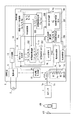
図1は本発明の第1の実施例に係る光検出システムの構成を示すブロック図である。光検出システムは、光センサを駆動し、光センサの駆動結果から放電確率と光源からの受光量とを算出するものである。この光検出システムは、炎やLEDやランプなどの光源100(第1の光源)から生じる光(紫外線)を検出する光センサ1と、外部電源2と、光センサ1および外部電源2が接続された演算装置3と、発生した光が光源100からの光と共に光センサ1に入射するように設置された追加光源101(第2の光源)とを備えている。
[Configuration and operation of optical detection system]
FIG. 1 is a block diagram showing a configuration of a photodetection system according to a first embodiment of the present invention. The photodetector system drives the photosensor and calculates the discharge probability and the amount of light received from the light source from the drive result of the photosensor. In this light detection system, a
光センサ1は、両端部が塞がれた円筒状の外囲器と、この外囲器の両端部を貫通する2本の電極ピンと、外囲器内部において電極ピンにより互いに平行に支持された2枚の電極とを備えた光電管から構成されている。このような光センサ1では、電極支持ピンを介して電極間に所定の電圧を印加した状態において、光源100に対向配置された一方の電極に紫外線が照射されると、光電効果によりその電極から電子が放出され、電極間に放電電流が流れる。
The
外部電源2は、例えば、100[V]または200[V]の電圧値を有する交流の商用電源からなる。
The
演算装置3は、外部電源2に接続された電源回路11と、この電源回路11に接続された印加電圧生成回路12およびトリガ回路13と、光センサ1の下流側の端子1bと接地ラインGNDとの間に直列に接続された抵抗R1とR2とからなる分圧抵抗14と、この分圧抵抗14の抵抗R1とR2との接続点Paに生じる電圧(参照電圧)Vaを光センサ1に流れる電流Iとして検出する電流検出回路15と、印加電圧生成回路12とトリガ回路13と電流検出回路15とが接続された処理回路16と、追加光源101の点灯/消灯を制御する光源制御部21とを備えている。
The
電源回路11は、外部電源2から入力される交流電力を、印加電圧生成回路12およびトリガ回路13に供給する。また、演算装置3の駆動用の電力は、電源回路11より取得される。ただし、交流/直流を問わず別電源から駆動用の電力を取得するように構成することもできる。
The
印加電圧生成回路12(印加電圧生成部)は、電源回路11により印加される交流電圧を所定の値まで昇圧させて光センサ1に印加する。本実施例では、処理回路16からの矩形パルスPSと同期した200[V]のパルス状の電圧(光センサ1の放電開始電圧VST以上の電圧)を駆動パルス電圧PMとして生成し、この生成した駆動パルス電圧PMを光センサ1に印加する。図2に光センサ1に印加される駆動パルス電圧PMを示す。駆動パルス電圧PMは、処理回路16からの矩形パルスPSと同期しており、そのパルス幅Tは矩形パルスPSのパルス幅と等しい。処理回路16からの矩形パルスPSについては後述する。
The applied voltage generation circuit 12 (applied voltage generation unit) boosts the AC voltage applied by the
トリガ回路13は、電源回路11により印加される交流電圧の所定の値点を検出し、この検出結果を処理回路16に入力する。本実施例において、トリガ回路13は、電圧値が最小となる最小値点を所定の値点(トリガ時点)として検出する。このように交流電圧について所定の値点を検出することにより、その交流電圧の1周期を検出することが可能となる。
The
分圧抵抗14は、抵抗R1とR2との分圧電圧として参照電圧Vaを生成し、電流検出回路15に入力する。ここで、光センサ1の上流側の端子1aに印加される駆動パルスPMの電圧値は、上述したように200[V]という高電圧となっているので、光センサ1の電極間に電流が流れた時にその下流側の端子1bに生じる電圧をそのまま電流検出回路15に入力すると電流検出回路15に大きな負荷がかかることとなる。このため、本実施例では、分圧抵抗14によって電圧値が低い参照電圧Vaを生成し、これを電流検出回路15に入力するようにしている。
The
電流検出回路15(電流検出部)は、分圧抵抗14から入力される参照電圧Vaを光センサ1の放電電流Iとして検出し、この検出した参照電圧Vaを検出電圧Vpvとして処理回路16に入力する。
処理回路16は、矩形パルス生成部17と、A/D変換部18と、感度パラメータ記憶部19と、中央処理部20とを備えている。
The current detection circuit 15 (current detection unit) detects the reference voltage Va input from the
The
矩形パルス生成部17は、トリガ回路13がトリガ時点を検出する毎に、すなわち電源回路11からトリガ回路13に印加される交流電圧の1周期毎に、パルス幅Tの矩形パルスPSを生成する。この矩形パルス生成部17が生成する矩形パルスPSが印加電圧生成回路12へ送られる。矩形パルス生成部17と印加電圧生成回路12とは、駆動パルス電圧PMのパルス幅を調整可能である。すなわち、矩形パルス生成部17が矩形パルスPSのパルス幅を所望の値に設定することにより、矩形パルスPSと等しいパルス幅の駆動パルス電圧PMが印加電圧生成回路12から出力される。
A/D変換部18は、電流検出回路15からの検出電圧VpvをA/D変換し、中央処理部20へ送る。
The rectangular
The A / D conversion unit 18 A / D converts the detection voltage Vpv from the
中央処理部20は、プロセッサや記憶装置からなるハードウェアと、これらのハードウェアと協働して各種機能を実現させるプログラムとによって実現され、放電判定部201と、放電確率算出部202,203と、パルス印加数積算部204と、印加数判定部205と、受光量算出部206と、受光量判定部207として機能する。
The
中央処理部20において、放電判定部201は、電流検出回路15によって検出された光センサ1の放電電流に基づいて光センサ1の放電を検出する。具体的には、放電判定部201は、光センサ1に駆動パルス電圧PMが印加される毎(矩形パルスPSが生成される毎)に、A/D変換部18から入力される検出電圧Vpvと予め定められている閾値電圧Vthとを比較し(図2参照)、検出電圧Vpvが閾値電圧Vthを超えた場合に光センサ1が放電したと判定し、放電回数nを1増やす。
In the
放電確率算出部202は、光センサ1に印加された駆動パルス電圧PMの印加回数Nが所定数を超えたとき(矩形パルスPSのパルス数が所定数を超えたとき)に、放電判定部201によって検出された放電回数nと駆動パルス電圧PMの印加回数Nとから光センサ1の放電確率Pを算出する。
The discharge
この放電確率Pをフレーム信号として出力する。ある動作条件、受光量Q0(Q0≠0)、パルス幅T0における放電確率P0が既知であるとする。例えば光検出システムの出荷検査において、定められた受光量とパルス幅における放電確率Pを測定しておく方法がある。このとき、受光量Q、パルス幅T、放電確率Pの関係は、式(7)となる。ただし、P=0はQ=0とする。本発明では、P=0のときとP=1のときは、受光量Qの算出処理から除外する。 This discharge probability P is output as a frame signal. Certain operating conditions, the received light amount Q 0 (Q 0 ≠ 0) , the discharge probability P 0 of the pulse width T 0 is known. For example, in the shipping inspection of a photodetection system, there is a method of measuring the discharge probability P at a predetermined light receiving amount and pulse width. At this time, the relationship between the received light amount Q, the pulse width T, and the discharge probability P is given by the equation (7). However, P = 0 is Q = 0. In the present invention, when P = 0 and P = 1, it is excluded from the calculation process of the received light amount Q.
いま、Q0,T0,P0が既知で、Tは光検出システムが制御しているパルス幅なので既知である。複数回の駆動パルス電圧PMを光センサ1に印加し、放電回数nを測定し、放電確率Pを算出すれば、未知数である受光量Qを式(7)から算出することができる。この受光量Qをフレーム信号として出力してもよい。
Now, Q 0 , T 0 , and P 0 are known, and T is known because the pulse width is controlled by the photodetection system. If the drive pulse voltage PM is applied to the
[ノイズを考慮した光検出システムの動作]
式(7)から、ある動作条件、受光量Q0、パルス幅T0における放電確率PaAが既知であるとし、受光量Q、パルス幅T、放電確率Pの関係は、式(8)で与えられる。
[Operation of photodetection system considering noise]
From the equation (7), it is assumed that the discharge probability P aA at a certain operating condition, the light receiving amount Q 0 , and the pulse width T 0 is known, and the relationship between the received light amount Q, the pulse width T, and the discharge probability P is expressed by the equation (8). Given.
![]()
![]()
光センサ1の放電と時間との関係としては、下記の2とおりが考えられる。
(a)駆動パルス電圧PMの印加中に一律の確率で現れる放電(式(8))。
(b)駆動パルス電圧PMの立ち上がり若しくは立ち下がり時に現れる放電。
The following two can be considered as the relationship between the discharge of the
(A) Discharge that appears with a uniform probability while the drive pulse voltage PM is applied (Equation (8)).
(B) Drive pulse voltage A discharge that appears when the PM rises or falls.
次に、光センサ1の放電と受光量との関係は、下記の2とおりが考えられる。
(A)受光量と式(8)の関係に従って現れる放電。
(B)受光量と無関係に表れる放電。
Next, the relationship between the discharge of the
(A) A discharge that appears according to the relationship between the amount of light received and the formula (8).
(B) Discharge that appears regardless of the amount of light received.
表1のマトリクスのとおり、(a)、(b)と(A)、(B)の組み合わせで光センサ1のノイズ放電を類型できる。本発明では、(a)と(A)の組み合わせ(aA)、(a)と(B)の組み合わせ(aB)、(b)と(A)の組み合わせ(bA)、(b)と(B)の組み合わせ(bB)が確実に観測される可能性が高いと考えられる。
As shown in the matrix of Table 1, the noise discharge of the
aAの組み合わせの放電は、「感度」と呼ばれる正常な放電(式(8)に組み込み済み)である。aBの組み合わせの放電は、熱電子などがトリガとなる紫外線量に無関係な放電である。bAの組み合わせの放電は、突入電流や残存イオンにより駆動パルス電圧の立ち上がり若しくは立ち下がり時に限定的に発生する放電のうち光量に依存する放電である。bBの組み合わせの放電は、突入電流や残存イオンにより駆動パルス電圧の立ち上がり若しくは立ち下がり時に限定的に発生する放電のうち光量に依存しない放電である。 The discharge of the combination of aA is a normal discharge called "sensitivity" (already incorporated in equation (8)). The discharge of the combination of aB is a discharge irrelevant to the amount of ultraviolet rays triggered by thermions and the like. The discharge of the combination of bA is a discharge that depends on the amount of light among the discharges that are limitedly generated when the drive pulse voltage rises or falls due to the inrush current or the residual ions. The discharge of the combination of bB is a discharge that does not depend on the amount of light among the discharges that are limitedly generated when the drive pulse voltage rises or falls due to the inrush current or the residual ions.
なお、表1に類型化したものはUV(ultraviolet)故障モードの全てではない。例えば放電が切れない、感度波長が異なるなど、表1に含まれない故障モードがある。 It should be noted that the ones categorized in Table 1 are not all of the UV (ultraviolet) failure modes. For example, there are failure modes not included in Table 1, such as discharge not being cut off and sensitivity wavelengths being different.
以上のaAの放電と3種のaB,bA,bBのノイズ放電とは、式(9)の形で表すことができる。 The above discharge of aA and the noise discharge of the three types of aB, bA, and bB can be expressed in the form of equation (9).
式(9)において、PaBは受光量Q、パルス幅TにおけるaBの放電確率、PbAは受光量Q、パルス幅TにおけるbAの放電確率、PbBは受光量Q、パルス幅TにおけるbBの放電確率である。 In equation (9), P aB is the light receiving amount Q, the discharge probability of aB at the pulse width T, P bA is the light receiving amount Q, the discharge probability of bA at the pulse width T, P bB is the light receiving amount Q, bB at the pulse width T. Discharge probability of.
[放電確率PaA,PbAの算出方法]
式(9)において、放電確率PaA,PbA、光量Qが未知数で、放電確率PaB,PbBが既知であるとする。例えば光源100に加えて、光量が既知の追加光源101を点灯させたときの受光量をQ1、追加光源101を消灯した状態の光源100のみのときの受光量をQ2(Q1≠Q2)とすると、受光量Q1とQ2との差は追加光源101の光量となるので、受光量Q1,Q2が未知の値であっても、Q1−Q2は既知の値となる。受光量Q1のときの放電確率を1Pとして、受光量Q1と放電確率1Pとを式(9)に代入すると、式(10)となる。
[Calculation method of discharge probabilities P aA and P bA]
In equation (9), it is assumed that the discharge probabilities P aA , P bA , and the amount of light Q are unknown, and the discharge probabilities P aB , P bB are known. For example, in addition to the
また、受光量Q2のときの放電確率を2Pとして、受光量Q2と放電確率2Pとを式(9)に代入すると、式(11)となる。 Further, if the discharge probability when the light receiving amount Q 2 is 2 P and the light receiving amount Q 2 and the discharge probability 2 P are substituted into the equation (9), the equation (11) is obtained.
式(10)を式(11)で除すると、式(12)となる。 Dividing equation (10) by equation (11) yields equation (12).
さらに、駆動パルス電圧PMのパルス幅がT1で、受光量がQ1のときの放電確率を1 1P、駆動パルス電圧PMのパルス幅がT1で、受光量がQ2のときの放電確率を2 1Pとすると、式(12)より式(13)が得られる。 Further, the pulse width of the drive pulse voltage PM is at T 1, 1 1 P a discharge probability when the amount of received light Q 1, the pulse width of the driving pulse voltage PM in the T 1, discharge when the amount of received light Q 2 ' Assuming that the probability is 2 1 P, the equation (13) can be obtained from the equation (12).
また、駆動パルス電圧PMのパルス幅がT2(T1≠T2)で、受光量がQ1のときの放電確率を1 2P、駆動パルス電圧PMのパルス幅がT2で、受光量がQ2のときの放電確率を2 2Pとすると、式(12)より式(14)が得られる。 Also, when the pulse width of the drive pulse voltage PM is T 2 (T 1 ≠ T 2 ) and the received light amount is Q 1 , the discharge probability is 1 2 P, and the pulse width of the drive pulse voltage PM is T 2 and the received light amount. If the discharge probability when is Q 2 is 2 2 P, the equation (14) can be obtained from the equation (12).
受光量Q1,Q2とパルス幅T1,T2を組み合わせて測定したときのそれぞれの放電確率の表記を表2にまとめる。 Table 2 summarizes the notation of each discharge probability when the received light amounts Q 1 and Q 2 and the pulse widths T 1 and T 2 are combined and measured.
式(13)を式(14)で除して変形すると、式(16)のように放電確率PaAを求めることができる。 By dividing the equation (13) by the equation (14) and transforming it, the discharge probability P aA can be obtained as in the equation (16).
さらに、式(16)を式(12)に代入することで、式(17)のように放電確率PbAを求めることができる。 Further, by substituting the equation (16) into the equation (12), the discharge probability P bA can be obtained as in the equation (17).
したがって、放電確率1 1P,2 1P,1 2P,2 2P,1P,2Pをそれぞれ測定すれば、放電確率PaA,PbAを得ることができる。
なお、T=T1としてもよい。この場合の放電確率PbAは式(18)のように求めることができる。
Therefore, the discharge probabilities P aA and P bA can be obtained by measuring the discharge probabilities 1 1 P, 2 1 P, 1 2 P, 2 2 P, 1 P, and 2 P, respectively.
In addition, T = T 1 may be set. The discharge probability P bA in this case can be obtained as in Eq. (18).
また、T=T2としてもよい。この場合の放電確率PbAは式(19)のように求めることができる。 Further, T = T 2 may be set. The discharge probability P bA in this case can be obtained as in Eq. (19).
[受光量Qの算出方法]
式(12)を変形すると、式(20)となる。
[Calculation method of received light amount Q]
When the equation (12) is modified, it becomes the equation (20).
上記のとおり、T=T1としてもよい。この場合の受光量Qは式(21)のように求めることができる。 As described above, T = T 1 may be set. The light receiving amount Q in this case can be obtained as in the equation (21).
また、T=T2としてもよい。この場合の受光量Qは式(22)のように求めることができる。 Further, T = T 2 may be set. The light receiving amount Q in this case can be obtained as in the equation (22).
このように、式(16)〜式(19)から放電確率PaA,PbAが既知であるとき、式(20)〜式(22)により受光量Qを得ることができる。
したがって、放電確率PaB,PbBのうち少なくとも一方が未知数の場合でも、検出対象の光源100に加えて、光量が既知の追加光源101を使用することで、受光量Qを得ることができる。
As described above, when the discharge probabilities P aA and P bA are known from the equations (16) to (19), the received light amount Q can be obtained by the equations (20) to (22).
Therefore, even when at least one of the discharge probabilities P aB and P bB is unknown, the light receiving amount Q can be obtained by using the additional
以下、本実施例の光検出システムの動作について更に詳細に説明する。図3、図4は本実施例の光検出システムの動作を説明するフローチャートである。
まず、放電確率算出部202は、パルス幅制御のための変数iを1に初期化する(図3ステップS100)。そして、放電確率算出部202は、光源制御部21に追加光源101を点灯するよう指示する。
Hereinafter, the operation of the photodetector system of this embodiment will be described in more detail. 3 and 4 are flowcharts for explaining the operation of the photodetection system of this embodiment.
First, the discharge
放電確率算出部202からの指示に応じて、光源制御部21は、追加光源101を点灯させる(図3ステップS101)。このときの光センサ1の受光量は未知の値Q1である。追加光源101としては、例えばLEDがある。
In response to an instruction from the discharge
放電確率算出部202は、変数iが3より小さい場合(図3ステップS102においてYES)、矩形パルス生成部17に指示して駆動パルス電圧PMの印加を開始させる。放電確率算出部202からの指示に応じて、矩形パルス生成部17は、矩形パルスPSのパルス幅を所定の値Ti=T1に設定する。このパルス幅の設定により、印加電圧生成回路12は、パルス幅Ti=T1の駆動パルス電圧PMを光センサ1の1対の端子1a,1b間に印加する(図3ステップS103)。
When the variable i is smaller than 3 (YES in step S102 in FIG. 3), the discharge
放電判定部201は、電流検出回路15からの検出電圧Vpvと予め定められている閾値電圧Vthとを比較し、検出電圧Vpvが閾値電圧Vthを超えた場合に光センサ1が放電したと判定する。放電判定部201は、光センサ1が放電したと判定すると、これを1回として放電回数1 in=1 1nをカウントする(図3ステップS104)。放電回数1 1nと後述する駆動パルス電圧PMの印加回数1 1Nの初期値が共に0であることは言うまでもない。こうして、ステップS103,S104の処理が繰り返し実行される。
The
パルス印加数積算部204は、矩形パルス生成部17から出力される矩形パルスPSを数えることにより、駆動パルス電圧PMの印加回数1 iNを数える。
印加数判定部205は、駆動パルス電圧PMの印加回数1 iNを所定数Nthと比較する。
The pulse application number integrating unit 204 counts the number of application times 1 i N of the drive pulse voltage PM by counting the rectangular pulse PS output from the rectangular
The application number determination unit 205 compares the application frequency 1 i N of the drive pulse voltage PM with the predetermined number N th.
放電確率算出部202は、ステップS103によるパルス幅Ti=T1の駆動パルス電圧PMの印加開始時からの駆動パルス電圧PMの印加回数1 iN=1 1Nが所定数Nthを超えたと印加数判定部205が判定したとき(図3ステップS105においてYES)、このときの駆動パルス電圧PMの印加回数1 iN=1 1Nと放電判定部201によって検出された放電回数1 in=1 1nとに基づいて、式(23)により放電確率1 1Pを算出する(図3ステップS106)。
1 1P=1 1n/1 1N ・・・(23)
The discharge probability calculation unit 202 applies that the number of times 1 i N = 1 1 N of the drive pulse voltage PM applied from the start of application of the drive pulse voltage PM of the pulse width T i = T 1 in step S103 exceeds a predetermined number Nth. the number (YES in Fig. 3 step S105) when the
1 1 P = 1 1 n / 1 1 N ・ ・ ・ (23)
放電確率1 1Pの算出後、放電確率算出部202は、パルス幅制御のための変数iを1増やす(図3ステップS107)。放電確率算出部202は、変数iが3より小さい場合(ステップS102においてYES)、矩形パルス生成部17に指示して駆動パルス電圧PMの再度の印加を開始させる。
After calculating the discharge probability 1 1 P, the discharge
放電確率算出部202からの指示に応じて、矩形パルス生成部17は、矩形パルスPSの出力を一旦停止した後、矩形パルスPSのパルス幅を所定の値Ti=T2(T1≠T2)に設定する。このパルス幅の設定により、印加電圧生成回路12は、パルス幅Ti=T2の駆動パルス電圧PMを光センサ1の1対の端子1a,1b間に印加する(ステップS103)。
In response to the instruction from the discharge
放電判定部201は、上記と同様に電流検出回路15からの検出電圧Vpvと閾値電圧Vthとを比較し、検出電圧Vpvが閾値電圧Vthを超えた場合に光センサ1が放電したと判定し、放電回数1 in=1 2nを1増やす(ステップS104)。放電回数1 2nと後述する駆動パルス電圧PMの印加回数1 2Nの初期値は共に0である。こうして、ステップS103,S104の処理が繰り返し実行される。
The
放電確率算出部202は、ステップS103によるパルス幅Ti=T2の駆動パルス電圧PMの印加開始時からの駆動パルス電圧PMの印加回数1 iN=1 2Nが所定数Nthを超えたと印加数判定部205が判定したとき(ステップS105においてYES)、このときの駆動パルス電圧PMの印加回数1 iN=1 2Nと放電判定部201によって検出された放電回数1 in=1 2nとに基づいて、式(24)により放電確率1 2Pを算出する(ステップS106)。
1 2P=1 2n/1 2N ・・・(24)
The discharge probability calculation unit 202 applies that the number of times 1 i N = 1 2 N of the drive pulse voltage PM applied from the start of application of the drive pulse voltage PM of the pulse width T i = T 2 in step S103 exceeds a predetermined number Nth. When the
1 2 P = 1 2 n / 1 2 N ・ ・ ・ (24)
放電確率1 2Pの算出後、放電確率算出部202は、パルス幅制御のための変数iを1増やす(ステップS107)。放電確率算出部202は、受光量Q1のときの測定が終了したとき、すなわち変数iが3に達したとき(ステップS102においてNO)、変数iを1に初期化する(図3ステップS108)。そして、放電確率算出部202は、光源制御部21に追加光源101を消灯するよう指示する。
After calculating the discharge probability 1 2 P, the discharge
放電確率算出部202からの指示に応じて、光源制御部21は、追加光源101を消灯させる(図3ステップS109)。このときの光センサ1の受光量は未知の値Q2である。上記のとおり、Q1−Q2は既知の値である。
In response to an instruction from the discharge
放電確率算出部202は、変数iが3より小さい場合(図3ステップS110においてYES)、矩形パルス生成部17に指示して駆動パルス電圧PMの印加を開始させる。放電確率算出部202からの指示に応じて、矩形パルス生成部17は、矩形パルスPSのパルス幅を所定の値Ti=T1に設定する。このパルス幅の設定により、印加電圧生成回路12は、パルス幅Ti=T1の駆動パルス電圧PMを光センサ1の1対の端子1a,1b間に印加する(図3ステップS111)。
When the variable i is smaller than 3 (YES in step S110 of FIG. 3), the discharge
放電判定部201は、上記と同様に電流検出回路15からの検出電圧Vpvと閾値電圧Vthとを比較し、検出電圧Vpvが閾値電圧Vthを超えた場合に光センサ1が放電したと判定し、放電回数2 in=2 1nを1増やす(ステップS112)。放電回数2 1nと後述する駆動パルス電圧PMの印加回数2 1Nの初期値は共に0である。こうして、ステップS111,S112の処理が繰り返し実行される。
The
放電確率算出部202は、ステップS111によるパルス幅Ti=T1の駆動パルス電圧PMの印加開始時からの駆動パルス電圧PMの印加回数2 iN=2 1Nが所定数Nthを超えたと印加数判定部205が判定したとき(図3ステップS113においてYES)、このときの駆動パルス電圧PMの印加回数2 iN=2 1Nと放電判定部201によって検出された放電回数2 in=2 1nとに基づいて、式(25)により放電確率2 1Pを算出する(図3ステップS114)。
2 1P=2 1n/2 1N ・・・(25)
The discharge probability calculation unit 202 applies when the number of times 2 i N = 2 1 N of the drive pulse voltage PM applied from the start of application of the drive pulse voltage PM of the pulse width T i = T 1 in step S111 exceeds a predetermined number Nth. the number (YES in Fig. 3 step S113) when the
2 1 P = 2 1 n / 2 1 N ・ ・ ・ (25)
放電確率2 1Pの算出後、放電確率算出部202は、パルス幅制御のための変数iを1増やす(図3ステップS115)。放電確率算出部202は、変数iが3より小さい場合(ステップS110においてYES)、矩形パルス生成部17に指示して駆動パルス電圧PMの再度の印加を開始させる。
After calculating the discharge probability 2 1 P, the discharge
放電確率算出部202からの指示に応じて、矩形パルス生成部17は、矩形パルスPSの出力を一旦停止した後、矩形パルスPSのパルス幅を所定の値Ti=T2(T1≠T2)に設定する。このパルス幅の設定により、印加電圧生成回路12は、パルス幅Ti=T2の駆動パルス電圧PMを光センサ1の1対の端子1a,1b間に印加する(ステップS111)。
In response to the instruction from the discharge
放電判定部201は、上記と同様に電流検出回路15からの検出電圧Vpvと閾値電圧Vthとを比較し、検出電圧Vpvが閾値電圧Vthを超えた場合に光センサ1が放電したと判定し、放電回数2 in=2 2nを1増やす(ステップS112)。放電回数2 2nと後述する駆動パルス電圧PMの印加回数2 2Nの初期値は共に0である。こうして、ステップS111,S112の処理が繰り返し実行される。
The
放電確率算出部202は、ステップS111によるパルス幅Ti=T2の駆動パルス電圧PMの印加開始時からの駆動パルス電圧PMの印加回数2 iN=2 2Nが所定数Nthを超えたと印加数判定部205が判定したとき(ステップS113においてYES)、このときの駆動パルス電圧PMの印加回数2 iN=2 2Nと放電判定部201によって検出された放電回数2 in=2 2nとに基づいて、式(26)により放電確率2 2Pを算出する(ステップS114)。
2 2P=2 2n/2 2N ・・・(26)
The discharge probability calculation unit 202 applies that the number of times 2 i N = 2 2 N of the drive pulse voltage PM applied from the start of application of the drive pulse voltage PM of the pulse width T i = T 2 in step S111 exceeds a predetermined number Nth. When the
2 2 P = 2 2 n / 2 2 N ・ ・ ・ (26)
放電確率2 2Pの算出後、放電確率算出部202は、パルス幅制御のための変数iを1増やす(ステップS115)。放電確率算出部202は、受光量Q2のときの測定が終了したとき、すなわち変数iが3に達したとき(ステップS110においてNO)、光源制御部21に追加光源101を点灯するよう指示した後に、矩形パルス生成部17に指示して駆動パルス電圧PMの印加を開始させる。
放電確率算出部202からの指示に応じて、光源制御部21は、追加光源101を点灯させる(図3ステップS116)。このときの光センサ1の受光量はQ1である。
After calculating the discharge probability 2 2 P, the discharge
In response to an instruction from the discharge
放電確率算出部202からの指示に応じて、矩形パルス生成部17は、矩形パルスPSのパルス幅を所定の値Tに設定する。このパルス幅の設定により、印加電圧生成回路12は、パルス幅Tの駆動パルス電圧PMを光センサ1の1対の端子1a,1b間に印加する(図3ステップS117)。
In response to the instruction from the discharge
放電判定部201は、上記と同様に電流検出回路15からの検出電圧Vpvと閾値電圧Vthとを比較し、検出電圧Vpvが閾値電圧Vthを超えた場合に光センサ1が放電したと判定し、放電回数n1を1増やす(図3ステップS118)。放電回数n1と後述する駆動パルス電圧PMの印加回数N1の初期値は共に0である。こうして、ステップS117,S118の処理が繰り返し実行される。
The
放電確率算出部202は、ステップS117による駆動パルス電圧PMの印加開始時からの駆動パルス電圧PMの印加回数N1が所定数Nthを超えたと印加数判定部205が判定したとき(図3ステップS119においてYES)、このときの駆動パルス電圧PMの印加回数N1と放電判定部201によって検出された放電回数n1とに基づいて、式(27)により放電確率1Pを算出する(図3ステップS120)。
1P=n1/N1 ・・・(27)
When the discharge probability calculation unit 202 determines that the number of times N 1 of the drive pulse voltage PM applied from the start of application of the drive pulse voltage PM in step S117 exceeds a predetermined number Nth, the application
1 P = n 1 / N 1 ... (27)
放電確率1Pの算出後、放電確率算出部202は、光源制御部21に追加光源101を消灯するよう指示した後に、矩形パルス生成部17に指示して駆動パルス電圧PMの印加を開始させる。放電確率算出部202からの指示に応じて、光源制御部21は、追加光源101を消灯させる(図3ステップS121)。このときの光センサ1の受光量はQ2である。
After calculating the discharge probability 1 P, the discharge
放電確率算出部202からの指示に応じて、矩形パルス生成部17は、矩形パルスPSの出力を一旦停止した後、矩形パルスPSのパルス幅を再度、所定の値Tに設定する。このパルス幅の設定により、印加電圧生成回路12は、パルス幅Tの駆動パルス電圧PMを光センサ1の1対の端子1a,1b間に印加する(図3ステップS122)。
In response to the instruction from the discharge
放電判定部201は、上記と同様に電流検出回路15からの検出電圧Vpvと閾値電圧Vthとを比較し、検出電圧Vpvが閾値電圧Vthを超えた場合に光センサ1が放電したと判定し、放電回数n2を1増やす(図3ステップS123)。放電回数n2と後述する駆動パルス電圧PMの印加回数N2の初期値は共に0である。こうして、ステップS122,S123の処理が繰り返し実行される。
The
放電確率算出部202は、ステップS122による駆動パルス電圧PMの印加開始時からの駆動パルス電圧PMの印加回数N2が所定数Nthを超えたと印加数判定部205が判定したとき(図3ステップS124においてYES)、このときの駆動パルス電圧PMの印加回数N2と放電判定部201によって検出された放電回数n2とに基づいて、式(28)により放電確率2Pを算出する(図3ステップS125)。
2P=n2/N2 ・・・(28)
When the discharge probability calculation unit 202 determines that the number of times N 2 of application of the drive pulse voltage PM from the start of application of the drive pulse voltage PM in step S122 exceeds a predetermined number Nth by the application number determination unit 205 (FIG. 3, step S124). In YES), the discharge probability 2 P is calculated by the equation (28) based on the number of times N 2 of the drive pulse voltage PM applied at this time and the number of times of discharge n 2 detected by the discharge determination unit 201 (
2 P = n 2 / N 2 ... (28)
感度パラメータ記憶部19には、光センサ1の既知の感度パラメータとして、光センサ1の基準受光量Q0と、駆動パルス電圧PMの基準パルス幅T0と、追加光源101点灯時と消灯時の受光量の差Q1−Q2とが予め記憶されている。
感度パラメータ記憶部19に記憶される感度パラメータについては、例えば光検出システムの出荷検査において予め測定しておくものとする。
In the sensitivity
The sensitivity parameter stored in the sensitivity
放電確率2Pの算出後、放電確率算出部203は、放電確率算出部202によって算出された放電確率1 1P,2 1P,1 2P,2 2Pと、放電確率1 1P,2 1Pを求めたときの駆動パルス電圧PMのパルス幅T1と、放電確率1 2P,2 2Pを求めたときの駆動パルス電圧PMのパルス幅T2と、感度パラメータ記憶部19に記憶されているパラメータT0,Q0,Q1−Q2とに基づいて、放電確率PaAを式(16)により算出する(図3ステップS126)。放電確率PaAは、上記のとおり駆動パルス電圧PMのパルス幅が基準パルス幅T0で光センサ1の受光量が基準受光量Q0のときの正規の放電の放電確率である。
After calculating the discharge probability 2 P, the discharge probability calculation unit 203 has the discharge probabilities 1 1 P, 2 1 P, 1 2 P, 2 2 P and the discharge probabilities 1 1 P, 2 calculated by the discharge probability calculation unit 202. a pulse width T 1 of the drive pulse voltage PM when seeking 1 P, the pulse width T 2 of the drive pulse voltage PM when seeking discharge probability 1 2 P, 2 2 P, stored on the sensitivity
また、放電確率算出部203は、放電確率算出部202によって算出された放電確率1 1P,2 1P,1 2P,2 2P,1P,2Pと、放電確率1 1P,2 1Pを求めたときの駆動パルス電圧PMのパルス幅T1と、放電確率1 2P,2 2Pを求めたときの駆動パルス電圧PMのパルス幅T2と、放電確率1P,2Pを求めたときの駆動パルス電圧PMのパルス幅Tと、感度パラメータ記憶部19に記憶されているパラメータQ0,Q1−Q2とに基づいて、放電確率PbAを式(17)により算出する(図3ステップS127)。放電確率PbAは、上記のとおり駆動パルス電圧PMのパルス幅に依存せずに発生しかつ光センサ1の受光量に依存して発生する、光センサ1の光電効果による放電以外のノイズ成分による放電の確率である。
Further, the discharge probability calculation unit 203 includes discharge probabilities 1 1 P, 2 1 P, 1 2 P, 2 2 P, 1 P, 2 P and discharge probabilities 1 1 P, 2 calculated by the discharge probability calculation unit 202. a pulse width T 1 of the drive pulse voltage PM when seeking 1 P, the pulse width T 2 of the drive pulse voltage PM when seeking discharge probability 1 2 P, 2 2 P, discharge probability 1 P, 2 P The discharge probability P bA is calculated by Eq. (17) based on the pulse width T of the drive pulse voltage PM and the parameters Q 0 and Q 1 −Q 2 stored in the sensitivity parameter storage unit 19. (FIG. 3, step S127). As described above, the discharge probability P bA is due to noise components other than discharge due to the photoelectric effect of the
受光量算出部206は、放電確率算出部203によって算出された放電確率PaA,PbAが0より大きくかつ1未満の場合(図4ステップS128においてYES)、放電確率算出部202によって算出された放電確率1P,2Pと、放電確率1P,2Pを求めたときの駆動パルス電圧PMのパルス幅Tと、放電確率算出部203によって算出された放電確率PaA,PbAと、感度パラメータ記憶部19に記憶されているパラメータT0,Q1−Q2とに基づいて、式(20)により受光量Qを算出する(図4ステップS129)。
The light receiving
また、受光量算出部206は、放電確率PaA,PbAのうち少なくとも一方が0の場合(ステップS128においてNO)、受光量Qを0とするか、あるいは受光量Qを算出不可とする例外処理を行う(図4ステップS130)。また、受光量算出部206は、放電確率PaA,PbAのうち少なくとも一方が1の場合(ステップS128においてNO)、受光量Qを算出不可とする例外処理を行う(ステップS130)。
Further, when at least one of the discharge probabilities P aA and P bA is 0 (NO in step S128), the light receiving
次に、受光量判定部207は、受光量算出部206によって算出された受光量Qと所定の受光量閾値Qthとを比較し(図4ステップS131)、受光量Qが受光量閾値Qthを超えた場合(ステップS131においてYES)、火炎有りと判定する(図4ステップS132)。また、受光量判定部207は、受光量Qが受光量閾値Qth以下の場合(ステップS131においてNO)、火炎無しと判定する(図4ステップS133)。
Next, the light receiving
以上の説明から分かるように、本実施例では、ノイズ成分を除外した正規の放電の放電確率PaAと、駆動パルス電圧PMのパルス幅に依存せずに発生しかつ光センサ1の受光量に依存して発生する非正規の放電の放電確率PbAとを算出することができる。光センサ1の劣化に伴って放電確率PaA,PbAが変化すると考えられるので、放電確率PaA,PbAに基づく光センサ1の寿命判定を実現することが可能となる。
As can be seen from the above description, in this embodiment, the discharge probability PaA of the normal discharge excluding the noise component and the amount of light received by the
また、本実施例では、放電確率PaB,PbBのうち少なくとも一方が未知数の場合でも、受光量Qを算出することができ、求めた受光量Qから火炎の有無を精度良く検出することが可能となる。また、本実施例では、受光量Qにより光センサ1の誤った寿命判定をしてしまう可能性を低減することができる。
Further, in this embodiment, even when at least one of the discharge probabilities P aB and P bB is unknown, the light receiving amount Q can be calculated, and the presence or absence of a flame can be accurately detected from the obtained light receiving amount Q. It will be possible. Further, in this embodiment, it is possible to reduce the possibility that the life of the
なお、本実施例では、T≠T1≠T2としてもよいし、T=T1またはT=T2としてもよい。T=T1の場合には、図3、図4の処理の代わりに図5、図6に示す処理を行うことが可能である。図5のステップS100〜S115の処理は図3で説明したとおりである。 In this embodiment, T ≠ T 1 ≠ T 2 may be set, or T = T 1 or T = T 2 may be set. When T = T 1 , the processes shown in FIGS. 5 and 6 can be performed instead of the processes shown in FIGS. 3 and 4. The processing of steps S100 to S115 of FIG. 5 is as described with reference to FIG.
放電確率算出部203は、受光量Q2のときの測定が終了したとき、すなわち変数iが3に達したとき(図5ステップS110においてNO)、放電確率PaAを式(16)により算出する(図5ステップS126)。
また、放電確率算出部203は、放電確率算出部202によって算出された放電確率1 1P,2 1P,1 2P,2 2Pと、放電確率1 1P,2 1Pを求めたときの駆動パルス電圧PMのパルス幅T1と、放電確率1 2P,2 2Pを求めたときの駆動パルス電圧PMのパルス幅T2と、感度パラメータ記憶部19に記憶されているパラメータQ0,Q1−Q2とに基づいて、放電確率PbAを式(18)により算出する(図5ステップS127a)。
The discharge probability calculation unit 203 calculates the discharge probability P aA by the equation (16) when the measurement at the received light amount Q 2 is completed, that is, when the variable i reaches 3 (NO in step S110 of FIG. 5). (FIG. 5 step S126).
Further, when the discharge probability calculation unit 203 obtains the discharge probabilities 1 1 P, 2 1 P, 1 2 P, 2 2 P and the discharge probabilities 1 1 P, 2 1 P calculated by the discharge
図6のステップS128,S130〜S133の処理は図4で説明したとおりである。受光量算出部206は、放電確率算出部203によって算出された放電確率PaA,PbAが0より大きくかつ1未満の場合(図6ステップS128においてYES)、放電確率算出部202によって算出された放電確率1 1P,2 1Pと、放電確率1 1P,2 1Pを求めたときの駆動パルス電圧PMのパルス幅T1と、放電確率算出部203によって算出された放電確率PaA,PbAと、感度パラメータ記憶部19に記憶されているパラメータT0,Q1−Q2とに基づいて、式(21)により受光量Qを算出すればよい(図6ステップS129a)。
The processes of steps S128 and S130 to S133 of FIG. 6 are as described in FIG. The light receiving
T=T2の場合についても、T=T1の場合と同様である。T=T2の場合、放電確率算出部203は、図5のステップS127aにおいて放電確率PbAを式(19)により算出すればよい。T=T2の場合、受光量算出部206は、図6のステップS129aにおいて受光量Qを式(22)により算出すればよい。その他の処理は、T=T1の場合と同じである。
The case of T = T 2 is the same as the case of T = T 1 . When T = T 2 , the discharge probability calculation unit 203 may calculate the discharge probability P bA by the equation (19) in step S127a of FIG. When T = T 2 , the light receiving
なお、本実施例では、追加光源101を点灯した状態を第1の状態(パルス幅T1)、第2の状態(パルス幅T2)、第5の状態(パルス幅T)とし、追加光源101を消灯した状態を第3の状態(パルス幅T1)、第4の状態(パルス幅T2)、第6の状態(パルス幅T)として、Q1−Q2を正の値(Q1>Q2)としているが、Q1−Q2を負の値(Q1<Q2)としてもよい。
In this embodiment, the state in which the additional
具体的には、放電確率算出部202は、図3、図5のステップS101,S116において追加光源101を消灯状態とし、図3、図5のステップS109,S121において追加光源101を点灯させるようにすればよい。これにより、追加光源101が消灯し、パルス幅がT1の状態が第1の状態、追加光源101が消灯し、パルス幅がT2の状態が第2の状態、追加光源101が消灯し、パルス幅がTの状態が第5の状態、追加光源101が点灯し、パルス幅がT1の状態が第3の状態、追加光源101が点灯し、パルス幅がT2の状態が第4の状態、追加光源101が点灯し、パルス幅がTの状態が第6の状態となる。
Specifically, the discharge
ただし、図3のステップS121で追加光源101を点灯させた場合、放電確率算出部202は、放電確率2Pの算出後に光源制御部21に指示して追加光源101を消灯させる必要がある。また、図5のステップS109で追加光源101を点灯させた場合、放電確率算出部202は、ステップS110において変数iが3に達した後に光源制御部21に指示して追加光源101を消灯させる必要がある。
However, if allowed to light an additional
[第2の実施例]
次に、本発明の第2の実施例について説明する。図7は本発明の第2の実施例に係る光検出システムの構成を示すブロック図であり、図1と同一の構成には同一の符号を付してある。本実施例の光検出システムは、光センサ1と、外部電源2と、演算装置3aと、追加光源101とを備えている。
[Second Example]
Next, a second embodiment of the present invention will be described. FIG. 7 is a block diagram showing a configuration of a photodetection system according to a second embodiment of the present invention, and the same configuration as that of FIG. 1 is designated by the same reference numerals. The photodetector system of this embodiment includes an
演算装置3aは、電源回路11と、印加電圧生成回路12と、トリガ回路13と、分圧抵抗14と、電流検出回路15と、処理回路16aと、光源制御部21とを備えている。
処理回路16aは、矩形パルス生成部17aと、A/D変換部18と、感度パラメータ記憶部19と、中央処理部20aとを備えている。
The
The processing circuit 16a includes a square
中央処理部20aは、放電判定部201と、放電確率算出部202a,203aと、パルス印加数積算部204と、印加数判定部205と、受光量算出部206と、受光量判定部207として機能する。
The
[放電確率PaA,PbAの算出方法]
駆動パルス電圧PMのパルス幅がT1で、受光量がQ1のときの放電確率を1 1Pとして、パルス幅T1と受光量Q1と放電確率1 1Pとを式(9)に代入すると、式(29)となる。
[Calculation method of discharge probabilities P aA and P bA]
When the pulse width of the drive pulse voltage PM is T 1 and the light receiving amount is Q 1 , the discharge probability is 1 1 P, and the pulse width T 1 , the light receiving amount Q 1 and the discharge probability 1 1 P are given in the equation (9). Substituting, it becomes equation (29).
駆動パルス電圧PMのパルス幅がT2(T1≠T2)で、受光量がQ1のときの放電確率を1 2Pとして、パルス幅T2と受光量Q1と放電確率1 2Pとを式(9)に代入すると、式(30)となる。 When the pulse width of the drive pulse voltage PM is T 2 (T 1 ≠ T 2 ) and the light receiving amount is Q 1 , the discharge probability is 1 2 P, and the pulse width T 2 and the light receiving amount Q 1 and the discharge probability 1 2 P Substituting and into equation (9) yields equation (30).
駆動パルス電圧PMのパルス幅がT3で、受光量がQ2のときの放電確率を2 3Pとして、パルス幅T3と受光量Q2と放電確率2 3Pとを式(9)に代入すると、式(31)となる。 When the pulse width of the drive pulse voltage PM is T 3 and the light receiving amount is Q 2 , the discharge probability is 2 3 P, and the pulse width T 3 and the light receiving amount Q 2 and the discharge probability 2 3 P are given in the equation (9). Substituting, it becomes equation (31).
駆動パルス電圧PMのパルス幅がT4(T3≠T4)で、受光量がQ2のときの放電確率を2 4Pとして、パルス幅がT4と受光量Q2と放電確率2 4Pとを式(9)に代入すると、式(32)となる。 When the pulse width of the drive pulse voltage PM is T 4 (T 3 ≠ T 4 ) and the light receiving amount is Q 2 , the discharge probability is 2 4 P, and the pulse width is T 4 and the light receiving amount Q 2 and the discharge probability 2 4 Substituting P into equation (9) yields equation (32).
受光量Q1,Q2とパルス幅T1,T2,T3,T4を組み合わせて測定したときのそれぞれの放電確率の表記を表3にまとめる。 Table 3 summarizes the notation of each discharge probability when the received light amounts Q 1 , Q 2 and the pulse widths T 1 , T 2 , T 3 , and T 4 are measured in combination.
式(29)を式(30)で除すると、式(33)となる。 Dividing equation (29) by equation (30) yields equation (33).
式(31)を式(32)で除すると、式(34)となる。 Dividing equation (31) by equation (32) yields equation (34).
式(33)を式(34)で除すると、式(35)となる。 Dividing equation (33) by equation (34) yields equation (35).
T1−T2=T3−T4である場合、式(35)を変形すると、式(36)のように放電確率PaAを求めることができる。ここで、T1=T3,T2=T4としてもよいし、T1≠T3,T2≠T4としてもよい。 When T 1 − T 2 = T 3 − T 4 , the discharge probability P aA can be obtained by modifying the equation (35) as in the equation (36). Here, T 1 = T 3 and T 2 = T 4 may be set, or T 1 ≠ T 3 and T 2 ≠ T 4 may be set.
さらに、式(36)を式(12)に代入することで、式(37)のように放電確率PbAを求めることができる。 Further, by substituting the equation (36) into the equation (12), the discharge probability P bA can be obtained as in the equation (37).
以下、本実施例の光検出システムの動作について更に詳細に説明する。図8は本実施例の光検出システムの動作を説明するフローチャートである。図8のステップS100〜S107の処理は第1の実施例と同様である。 Hereinafter, the operation of the photodetector system of this embodiment will be described in more detail. FIG. 8 is a flowchart illustrating the operation of the photodetection system of this embodiment. The processing of steps S100 to S107 of FIG. 8 is the same as that of the first embodiment.
放電確率算出部202aは、受光量Q1のときの測定が終了したとき、すなわち変数iが3に達したとき(ステップS102においてNO)、光源制御部21に追加光源101を消灯するよう指示する。
放電確率算出部202aからの指示に応じて、光源制御部21は、追加光源101を消灯させる(図8ステップS109)。このときの光センサ1の受光量は未知の値Q2である。第1の実施例で説明したとおり、Q1−Q2は既知の値である。
Discharge
In response to an instruction from the discharge
放電確率算出部202aは、変数iが5より小さい場合(図8ステップS110bにおいてYES)、矩形パルス生成部17aに指示して駆動パルス電圧PMの印加を開始させる。放電確率算出部202aからの指示に応じて、矩形パルス生成部17aは、矩形パルスPSのパルス幅を所定の値Ti=T3に設定する。このパルス幅の設定により、印加電圧生成回路12は、パルス幅Ti=T3の駆動パルス電圧PMを光センサ1の1対の端子1a,1b間に印加する(図8ステップS111b)。
When the variable i is smaller than 5 (YES in step S110b in FIG. 8), the discharge
放電判定部201は、上記と同様に電流検出回路15からの検出電圧Vpvが閾値電圧Vthを超えた場合に光センサ1が放電したと判定し、放電回数2 in=2 3nを1増やす(図8ステップS112b)。放電回数2 3nと後述する駆動パルス電圧PMの印加回数2 3Nの初期値は共に0である。こうして、ステップS111b,S112bの処理が繰り返し実行される。
放電確率算出部202aは、ステップS111bによるパルス幅Ti=T3の駆動パルス電圧PMの印加開始時からの駆動パルス電圧PMの印加回数2 iN=2 3Nが所定数Nthを超えたと印加数判定部205が判定したとき(図8ステップS113bにおいてYES)、このときの駆動パルス電圧PMの印加回数2 iN=2 3Nと放電判定部201によって検出された放電回数2 in=2 3nとに基づいて、式(38)により放電確率2 3Pを算出する(図8ステップS114b)。
2 3P=2 3n/2 3N ・・・(38)
The discharge
2 3 P = 2 3 n / 2 3 N ・ ・ ・ (38)
放電確率2 3Pの算出後、放電確率算出部202aは、パルス幅制御のための変数iを1増やす(図8ステップS115)。放電確率算出部202aは、変数iが5より小さい場合(ステップS110bにおいてYES)、矩形パルス生成部17aに指示して駆動パルス電圧PMの再度の印加を開始させる。
After calculating the discharge probability 2 3 P, the discharge
放電確率算出部202aからの指示に応じて、矩形パルス生成部17aは、矩形パルスPSの出力を一旦停止した後、矩形パルスPSのパルス幅を所定の値Ti=T4(T3≠T4)に設定する。このパルス幅の設定により、印加電圧生成回路12は、パルス幅Ti=T4の駆動パルス電圧PMを光センサ1の1対の端子1a,1b間に印加する(ステップS111b)。
In response to the instruction from the discharge
放電判定部201は、電流検出回路15からの検出電圧Vpvが閾値電圧Vthを超えた場合に光センサ1が放電したと判定し、放電回数2 in=2 4nを1増やす(ステップS112b)。放電回数2 4nと後述する駆動パルス電圧PMの印加回数2 4Nの初期値は共に0である。こうして、ステップS111b,S112bの処理が繰り返し実行される。
放電確率算出部202aは、ステップS111bによるパルス幅Ti=T4の駆動パルス電圧PMの印加開始時からの駆動パルス電圧PMの印加回数2 iN=2 4Nが所定数Nthを超えたと印加数判定部205が判定したとき(ステップS113bにおいてYES)、このときの駆動パルス電圧PMの印加回数2 iN=2 4Nと放電判定部201によって検出された放電回数2 in=2 4nとに基づいて、式(39)により放電確率2 4Pを算出する(ステップS114)。
2 4P=2 4n/2 4N ・・・(39)
The discharge
2 4 P = 2 4 n / 2 4 N ・ ・ ・ (39)
放電確率2 4Pの算出後、放電確率算出部202aは、パルス幅制御のための変数iを1増やす(ステップS115)。放電確率算出部202aは、受光量Q2のときの測定が終了したとき、すなわち変数iが5に達したとき(ステップS110bにおいてNO)、光源制御部21に追加光源101を点灯するよう指示した後に、矩形パルス生成部17aに指示して駆動パルス電圧PMの印加を開始させる。
After calculating the discharge probability 2 4 P, the discharge
放電確率算出部202aからの指示に応じて、光源制御部21は、追加光源101を点灯させる(図8ステップS116)。このときの光センサ1の受光量はQ1である。図8のステップS117〜S125の処理は第1の実施例と同様である。
In response to an instruction from the discharge
放電確率2Pの算出後、放電確率算出部203aは、放電確率算出部202aによって算出された放電確率1 1P,1 2P,2 3P,2 4Pと、放電確率1 1Pを求めたときの駆動パルス電圧PMのパルス幅T1と、放電確率1 2Pを求めたときの駆動パルス電圧PMのパルス幅T2と、感度パラメータ記憶部19に記憶されているパラメータQ0,Q1−Q2とに基づいて、放電確率PaAを式(36)により算出する(図8ステップS126b)。
After calculating the discharge probability 2 P, the discharge probability calculation unit 203a obtains the discharge probabilities 1 1 P, 1 2 P, 2 3 P, 2 4 P and the discharge probabilities 1 1 P calculated by the discharge
また、放電確率算出部203aは、放電確率算出部202aによって算出された放電確率1 1P,1 2P,2 3P,2 4P,1P,2Pと、放電確率1 1Pを求めたときの駆動パルス電圧PMのパルス幅T1と、放電確率1 2Pを求めたときの駆動パルス電圧PMのパルス幅T2と、放電確率1P,2Pを求めたときの駆動パルス電圧PMのパルス幅Tと、感度パラメータ記憶部19に記憶されているパラメータQ0,T0,Q1−Q2とに基づいて、放電確率PbAを式(37)により算出する(図8ステップS127b)。
ステップS128以降の処理は図4で説明したとおりなので、図示は省略する。
Further, the discharge probability calculation unit 203a obtains the discharge probabilities 1 1 P, 1 2 P, 2 3 P, 2 4 P, 1 P, 2 P and the discharge probabilities 1 1 P calculated by the discharge
Since the processing after step S128 is as described with reference to FIG. 4, the illustration is omitted.
こうして、本実施例では、第1の実施例と同様の効果を得ることができる。なお、本実施例では、放電確率PaA,PbAと受光量Qとを算出しているが、放電確率PaA,PbAのみを算出する場合には、受光量算出部206と受光量判定部207とステップS128以降の処理は不要である。
Thus, in this embodiment, the same effect as that of the first embodiment can be obtained. In this embodiment, the discharge probabilities P aA and P bA and the light receiving amount Q are calculated, but when only the discharge probabilities P aA and P bA are calculated, the light receiving
また、本実施例では、追加光源101を点灯した状態を第1の状態(パルス幅T1)、第2の状態(パルス幅T2)、第5の状態(パルス幅T)とし、追加光源101を消灯した状態を第3の状態(パルス幅T3)、第4の状態(パルス幅T4)、第6の状態(パルス幅T)として、Q1−Q2を正の値(Q1>Q2)としているが、Q1−Q2を負の値(Q1<Q2)としてもよい。
Further, in this embodiment, the state in which the additional
具体的には、放電確率算出部202aは、図8のステップS101,S116において追加光源101を消灯状態とし、図8のステップS109,S121において追加光源101を点灯させるようにすればよい。これにより、追加光源101が消灯し、パルス幅がT1の状態が第1の状態、追加光源101が消灯し、パルス幅がT2の状態が第2の状態、追加光源101が消灯し、パルス幅がTの状態が第5の状態、追加光源101が点灯し、パルス幅がT3の状態が第3の状態、追加光源101が点灯し、パルス幅がT4の状態が第4の状態、追加光源101が点灯し、パルス幅がTの状態が第6の状態となる。
Specifically, the discharge
ただし、図8のステップS121で追加光源101を点灯させた場合、放電確率算出部202aは、放電確率2Pの算出後に光源制御部21に指示して追加光源101を消灯させる必要がある。
However, if allowed to light an additional
第1、第2の実施例では、光源100が火炎の場合を例に挙げて説明しているが、本発明の光検出システムは火炎以外の光源100にも適用可能である。
In the first and second embodiments, the case where the
第1、第2の実施例で説明した感度パラメータ記憶部19と中央処理部20,20aとは、CPU(Central Processing Unit)と記憶装置とインタフェースを備えたコンピュータと、これらのハードウェア資源を制御するプログラムによって実現することができる。
The sensitivity
このコンピュータの構成例を図9に示す。コンピュータは、CPU300と、記憶装置301と、インタフェース装置(I/F)302とを備えている。I/F302には、印加電圧生成回路12と矩形パルス生成部17,17aとA/D変換部18と光源制御部21などが接続される。このようなコンピュータにおいて、本発明の放電確率算出方法および受光量測定方法を実現させるためのプログラムは記憶装置301に格納される。CPU300は、記憶装置301に格納されたプログラムに従って第1、第2の実施例で説明した処理を実行する。
A configuration example of this computer is shown in FIG. The computer includes a
本発明は、光検出システムに適用することができる。また、本発明は、火炎以外の光の検出に対しても適用できる。 The present invention can be applied to photodetection systems. The present invention can also be applied to the detection of light other than flame.
1…光センサ、2…外部電源、3,3a…演算装置、11…電源回路、12…印加電圧生成回路、13…トリガ回路、14…分圧抵抗、15…電流検出回路、16,16a…処理回路、17,17a…矩形パルス生成部、18…A/D変換部、19…感度パラメータ記憶部、20,20a…中央処理部、21…光源制御部、100…光源、101…追加光源、201…放電判定部、202,202a,203,203a…放電確率算出部、204…パルス印加数積算部、205…印加数判定部、206…受光量算出部、207…受光量判定部。 1 ... Optical sensor, 2 ... External power supply, 3,3a ... Computational device, 11 ... Power supply circuit, 12 ... Applied voltage generation circuit, 13 ... Trigger circuit, 14 ... Voltage division resistance, 15 ... Current detection circuit, 16, 16a ... Processing circuit, 17, 17a ... Rectangular pulse generator, 18 ... A / D conversion unit, 19 ... Sensitivity parameter storage unit, 20, 20a ... Central processing unit, 21 ... Light source control unit, 100 ... Light source, 101 ... Additional light source, 201 ... Discharge determination unit, 202, 202a, 203, 203a ... Discharge probability calculation unit, 204 ... Pulse application number integration unit, 205 ... Application number determination unit, 206 ... Light reception amount calculation unit, 207 ... Light reception amount determination unit.
Claims (12)
発生した光が前記第1の光源からの光と共に前記光センサに入射するように設置された、光量が既知の第2の光源と、
前記第2の光源の点灯/消灯を制御するように構成された光源制御部と、
前記光センサの電極に駆動パルス電圧を周期的に印加するように構成された印加電圧生成部と、
前記光センサの放電電流を検出するように構成された電流検出部と、
この電流検出部によって検出された放電電流に基づいて前記光センサの放電を検出するように構成された放電判定部と、
前記第2の光源が点灯または消灯した第1の状態と、前記第2の光源の点灯/消灯の状態が前記第1の状態と同じで、かつ前記駆動パルス電圧のパルス幅が前記第1の状態と異なる第2の状態と、前記第2の光源の点灯/消灯の状態が前記第1、第2の状態と異なり、かつ前記駆動パルス電圧のパルス幅が前記第1の状態と同じ第3の状態と、前記第2の光源の点灯/消灯の状態が前記第3の状態と同じで、かつ前記駆動パルス電圧のパルス幅が前記第2の状態と同じ第4の状態のそれぞれについて、前記印加電圧生成部による前記駆動パルス電圧の印加回数と、この駆動パルス電圧の印加中に前記放電判定部によって検出された放電の回数とに基づいて放電確率を算出するように構成された第1の放電確率算出部と、
前記光センサの既知の感度パラメータとして、前記駆動パルス電圧の基準パルス幅と、前記光センサの基準受光量と、前記第1、第2の状態と前記第3、第4の状態とにおける前記光センサの受光量の差とを予め記憶するように構成された記憶部と、
前記記憶部に記憶されている感度パラメータと、前記第1、第2、第3、第4の状態のときに前記第1の放電確率算出部によって算出された放電確率と、前記第1、第2、第3、第4の状態のときの前記駆動パルス電圧のパルス幅とに基づいて、前記駆動パルス電圧のパルス幅が前記基準パルス幅で前記光センサの受光量が前記基準受光量のときの正規の放電の放電確率と、前記駆動パルス電圧のパルス幅に依存せずに発生しかつ前記光センサの受光量に依存して発生する、前記光センサの光電効果による放電以外のノイズ成分による非正規の放電の放電確率とを算出するように構成された第2の放電確率算出部と、
前記記憶部に記憶されている感度パラメータと、前記第1、第2、第3、第4の状態のときに前記第1の放電確率算出部によって算出された放電確率と、前記第1、第2、第3、第4の状態のときの前記駆動パルス電圧のパルス幅と、前記第2の放電確率算出部によって算出された放電確率とに基づいて、前記第1、第2の状態または前記第3、第4の状態のときの前記光センサの受光量を算出するように構成された受光量算出部とを備えることを特徴とする光検出システム。 An optical sensor configured to detect the light emitted from the first light source,
A second light source having a known amount of light, which is installed so that the generated light is incident on the optical sensor together with the light from the first light source,
A light source control unit configured to control the lighting / extinguishing of the second light source, and
An applied voltage generator configured to periodically apply a drive pulse voltage to the electrodes of the optical sensor,
A current detection unit configured to detect the discharge current of the optical sensor, and
A discharge determination unit configured to detect the discharge of the optical sensor based on the discharge current detected by the current detection unit, and a discharge determination unit.
The first state in which the second light source is turned on or off and the state in which the second light source is turned on / off are the same as in the first state, and the pulse width of the drive pulse voltage is the first state. A third state in which the second state different from the state and the lighting / extinguishing state of the second light source are different from the first and second states, and the pulse width of the driving pulse voltage is the same as the first state. And the fourth state in which the lighting / extinguishing state of the second light source is the same as that of the third state and the pulse width of the driving pulse voltage is the same as that of the second state. A first configuration configured to calculate the discharge probability based on the number of times the drive pulse voltage is applied by the applied voltage generator and the number of discharges detected by the discharge determination unit during the application of the drive pulse voltage. Discharge probability calculation unit and
As known sensitivity parameters of the optical sensor, the reference pulse width of the drive pulse voltage, the reference light receiving amount of the optical sensor, and the light in the first and second states and the third and fourth states. A storage unit configured to store the difference in the amount of light received by the sensor in advance,
The sensitivity parameters stored in the storage unit, the discharge probability calculated by the first discharge probability calculation unit in the first, second, third, and fourth states, and the first and first discharge probabilities. When the pulse width of the drive pulse voltage is the reference pulse width and the light receiving amount of the optical sensor is the reference light receiving amount based on the pulse width of the drive pulse voltage in the second, third, and fourth states. Due to the discharge probability of the normal discharge and the noise component other than the discharge due to the photoelectric effect of the optical sensor, which is generated independently of the pulse width of the drive pulse voltage and depending on the amount of light received by the optical sensor. A second discharge probability calculation unit configured to calculate the discharge probability of non-regular discharge,
The sensitivity parameters stored in the storage unit, the discharge probability calculated by the first discharge probability calculation unit in the first, second, third, and fourth states, and the first and first discharge probabilities. Based on the pulse width of the drive pulse voltage in the second, third, and fourth states and the discharge probability calculated by the second discharge probability calculation unit, the first, second state, or the above. A photodetection system including a light receiving amount calculation unit configured to calculate the light receiving amount of the optical sensor in the third and fourth states.
前記第2の放電確率算出部は、前記駆動パルス電圧の基準パルス幅をT0、前記光センサの基準受光量をQ0、前記第1、第2の状態と前記第3、第4の状態とにおける前記光センサの受光量の差をQ1−Q2、前記第1の状態のときに前記第1の放電確率算出部によって算出された放電確率を1 1P、前記第2の状態のときに前記第1の放電確率算出部によって算出された放電確率を1 2P、前記第3の状態のときに前記第1の放電確率算出部によって算出された放電確率を2 1P、前記第4の状態のときに前記第1の放電確率算出部によって算出された放電確率を2 2P、前記第1、第3の状態のときの前記駆動パルス電圧のパルス幅をT1、前記第2、第4の状態のときの前記駆動パルス電圧のパルス幅をT2、前記正規の放電の放電確率をPaA、前記非正規の放電の放電確率をPbA、前記第1、第2の状態または前記第3、第4の状態のときの前記光センサの受光量をQとしたとき、
前記受光量算出部は、
The second discharge probability calculation unit sets the reference pulse width of the drive pulse voltage to T 0 , sets the reference light receiving amount of the optical sensor to Q 0 , and sets the first and second states and the third and fourth states. The difference in the amount of light received by the optical sensor is Q 1 −Q 2 , the discharge probability calculated by the first discharge probability calculation unit in the first state is 1 1 P, and the difference in the second state is Sometimes, the discharge probability calculated by the first discharge probability calculation unit is 1 2 P, and the discharge probability calculated by the first discharge probability calculation unit in the third state is 2 1 P, the first. The discharge probability calculated by the first discharge probability calculation unit in the state of 4 is 2 2 P, the pulse width of the drive pulse voltage in the first and third states is T 1 , and the second. , The pulse width of the drive pulse voltage in the fourth state is T 2 , the discharge probability of the normal discharge is P aA , the discharge probability of the non-regular discharge is P bA , and the first and second states. Or, when the amount of light received by the optical sensor in the third and fourth states is Q,
The light receiving amount calculation unit
発生した光が前記第1の光源からの光と共に前記光センサに入射するように設置された、光量が既知の第2の光源と、
前記第2の光源の点灯/消灯を制御するように構成された光源制御部と、
前記光センサの電極に駆動パルス電圧を周期的に印加するように構成された印加電圧生成部と、
前記光センサの放電電流を検出するように構成された電流検出部と、
この電流検出部によって検出された放電電流に基づいて前記光センサの放電を検出するように構成された放電判定部と、
前記第2の光源が点灯または消灯した第1の状態と、前記第2の光源の点灯/消灯の状態が前記第1の状態と同じで、かつ前記駆動パルス電圧のパルス幅が前記第1の状態と異なる第2の状態と、前記第2の光源の点灯/消灯の状態が前記第1、第2の状態と異なり、かつ前記駆動パルス電圧のパルス幅が前記第1の状態と同じ第3の状態と、前記第2の光源の点灯/消灯の状態が前記第3の状態と同じで、かつ前記駆動パルス電圧のパルス幅が前記第2の状態と同じ第4の状態と、前記第2の光源の点灯/消灯の状態が前記第1、第2の状態と同じで、かつ前記駆動パルス電圧のパルス幅が前記第1、第3の状態または前記第2、第4の状態のどちらかと同じか、前記第1、第2、第3、第4の状態のいずれとも異なる第5の状態と、前記第2の光源の点灯/消灯の状態が前記第3、第4の状態と同じで、かつ前記駆動パルス電圧のパルス幅が前記第5の状態と同じ第6の状態のそれぞれについて、前記印加電圧生成部による前記駆動パルス電圧の印加回数と、この駆動パルス電圧の印加中に前記放電判定部によって検出された放電の回数とに基づいて放電確率を算出するように構成された第1の放電確率算出部と、
前記光センサの既知の感度パラメータとして、前記駆動パルス電圧の基準パルス幅と、前記光センサの基準受光量と、前記第1、第2、第5の状態と前記第3、第4、第6の状態とにおける前記光センサの受光量の差とを予め記憶するように構成された記憶部と、
前記記憶部に記憶されている感度パラメータと、前記第1、第2、第3、第4、第5、第6の状態のときに前記第1の放電確率算出部によって算出された放電確率と、前記第1、第2、第3、第4、第5、第6の状態のときの前記駆動パルス電圧のパルス幅とに基づいて、前記駆動パルス電圧のパルス幅が前記基準パルス幅で前記光センサの受光量が前記基準受光量のときの正規の放電の放電確率と、前記駆動パルス電圧のパルス幅に依存せずに発生しかつ前記光センサの受光量に依存して発生する、前記光センサの光電効果による放電以外のノイズ成分による非正規の放電の放電確率とを算出するように構成された第2の放電確率算出部と、
前記記憶部に記憶されている感度パラメータと、前記第5、第6の状態のときに前記第1の放電確率算出部によって算出された放電確率と、前記第5、第6の状態のときの前記駆動パルス電圧のパルス幅と、前記第2の放電確率算出部によって算出された放電確率とに基づいて、前記第5、第6の状態のときの前記光センサの受光量を算出するように構成された受光量算出部とを備えることを特徴とする光検出システム。 An optical sensor configured to detect the light emitted from the first light source,
A second light source having a known amount of light, which is installed so that the generated light is incident on the optical sensor together with the light from the first light source,
A light source control unit configured to control the lighting / extinguishing of the second light source, and
An applied voltage generator configured to periodically apply a drive pulse voltage to the electrodes of the optical sensor,
A current detection unit configured to detect the discharge current of the optical sensor, and
A discharge determination unit configured to detect the discharge of the optical sensor based on the discharge current detected by the current detection unit, and a discharge determination unit.
The first state in which the second light source is turned on or off and the state in which the second light source is turned on / off are the same as in the first state, and the pulse width of the drive pulse voltage is the first state. A third state in which the second state different from the state and the lighting / extinguishing state of the second light source are different from the first and second states, and the pulse width of the driving pulse voltage is the same as the first state. And the fourth state in which the lighting / extinguishing state of the second light source is the same as in the third state and the pulse width of the driving pulse voltage is the same as in the second state, and the second state. The lighting / extinguishing state of the light source is the same as that of the first and second states, and the pulse width of the driving pulse voltage is either the first or third state or the second or fourth state. The fifth state, which is the same or different from any of the first, second, third, and fourth states, and the lighting / extinguishing state of the second light source are the same as the third and fourth states. In addition, for each of the sixth states in which the pulse width of the drive pulse voltage is the same as the fifth state, the number of times the drive pulse voltage is applied by the applied voltage generator and the discharge during the application of the drive pulse voltage. A first discharge probability calculation unit configured to calculate the discharge probability based on the number of discharges detected by the determination unit, and a first discharge probability calculation unit.
As known sensitivity parameters of the optical sensor, the reference pulse width of the drive pulse voltage, the reference light receiving amount of the optical sensor, the first, second, and fifth states and the third, fourth, and sixth states. A storage unit configured to store in advance the difference in the amount of light received by the optical sensor from the state of
Sensitivity parameters stored in the storage unit and discharge probabilities calculated by the first discharge probability calculation unit in the first, second, third, fourth, fifth, and sixth states. Based on the pulse width of the drive pulse voltage in the first, second, third, fourth, fifth, and sixth states, the pulse width of the drive pulse voltage is the reference pulse width. The said, which is generated independently of the discharge probability of a normal discharge when the received amount of light received by the optical sensor is the reference received amount and the pulse width of the drive pulse voltage and is generated depending on the received amount of light received by the optical sensor. A second discharge probability calculation unit configured to calculate the discharge probability of non-regular discharge due to noise components other than the discharge due to the photoelectric effect of the optical sensor, and
Sensitivity parameters stored in the storage unit, discharge probabilities calculated by the first discharge probability calculation unit in the fifth and sixth states, and discharge probabilities in the fifth and sixth states. Based on the pulse width of the drive pulse voltage and the discharge probability calculated by the second discharge probability calculation unit, the amount of light received by the optical sensor in the fifth and sixth states is calculated. An optical detection system including a configured light receiving amount calculation unit.
前記第2の放電確率算出部は、前記駆動パルス電圧の基準パルス幅をT0、前記光センサの基準受光量をQ0、前記第1、第2、第5の状態と前記第3、第4、第6の状態とにおける前記光センサの受光量の差をQ1−Q2、前記第1の状態のときに前記第1の放電確率算出部によって算出された放電確率を1 1P、前記第2の状態のときに前記第1の放電確率算出部によって算出された放電確率を1 2P、前記第3の状態のときに前記第1の放電確率算出部によって算出された放電確率を2 1P、前記第4の状態のときに前記第1の放電確率算出部によって算出された放電確率を2 2P、前記第5の状態のときに前記第1の放電確率算出部によって算出された放電確率を1P、前記第6の状態のときに前記第1の放電確率算出部によって算出された放電確率を2P、前記第1、第3の状態のときの前記駆動パルス電圧のパルス幅をT1、前記第2、第4の状態のときの前記駆動パルス電圧のパルス幅をT2、前記第5、第6の状態のときの前記駆動パルス電圧のパルス幅をT、前記正規の放電の放電確率をPaA、前記非正規の放電の放電確率をPbA、前記第5、第6の状態のときの前記光センサの受光量をQとしたとき、
前記受光量算出部は、
The second discharge probability calculation unit sets the reference pulse width of the drive pulse voltage to T 0 , sets the reference light receiving amount of the optical sensor to Q 0 , and sets the first, second, and fifth states and the third and third states. The difference in the amount of light received by the optical sensor between the fourth and sixth states is Q 1 −Q 2 , and the discharge probability calculated by the first discharge probability calculation unit in the first state is 1 1 P. The discharge probability calculated by the first discharge probability calculation unit in the second state is 1 2 P, and the discharge probability calculated by the first discharge probability calculation unit in the third state is 2 1 P, the discharge probability calculated by the first discharge probability calculation unit in the fourth state is 2 2 P, calculated by the first discharge probability calculation unit in the fifth state. The discharge probability is 1 P, the discharge probability calculated by the first discharge probability calculation unit in the sixth state is 2 P, and the pulse of the drive pulse voltage in the first and third states. The width is T 1 , the pulse width of the drive pulse voltage in the second and fourth states is T 2 , the pulse width of the drive pulse voltage in the fifth and sixth states is T, and the normal When the discharge probability of the discharge of is P aA , the discharge probability of the non-regular discharge is P bA , and the light receiving amount of the optical sensor in the fifth and sixth states is Q,
The light receiving amount calculation unit
発生した光が前記第1の光源からの光と共に前記光センサに入射するように設置された、光量が既知の第2の光源と、
前記第2の光源の点灯/消灯を制御するように構成された光源制御部と、
前記光センサの電極に駆動パルス電圧を周期的に印加するように構成された印加電圧生成部と、
前記光センサの放電電流を検出するように構成された電流検出部と、
この電流検出部によって検出された放電電流に基づいて前記光センサの放電を検出するように構成された放電判定部と、
前記第2の光源が点灯または消灯した第1の状態と、前記第2の光源の点灯/消灯の状態が前記第1の状態と同じで、かつ前記駆動パルス電圧のパルス幅が前記第1の状態と異なる第2の状態と、前記第2の光源の点灯/消灯の状態が前記第1、第2の状態と異なり、かつ前記駆動パルス電圧のパルス幅が前記第1の状態と同じかまたは異なる第3の状態と、前記第2の光源の点灯/消灯の状態が前記第3の状態と同じで、かつ前記駆動パルス電圧のパルス幅が前記第3の状態と異なる第4の状態と、前記第2の光源の点灯/消灯の状態が前記第1、第2の状態と同じで、かつ前記駆動パルス電圧のパルス幅が前記第1、第2、第3、第4の状態のうち少なくとも1つと同じか、前記第1、第2、第3、第4の状態のいずれとも異なる第5の状態と、前記第2の光源の点灯/消灯の状態が前記第3、第4の状態と同じで、かつ前記駆動パルス電圧のパルス幅が前記第5の状態と同じ第6の状態のそれぞれについて、前記印加電圧生成部による前記駆動パルス電圧の印加回数と、この駆動パルス電圧の印加中に前記放電判定部によって検出された放電の回数とに基づいて放電確率を算出するように構成された第1の放電確率算出部と、
前記光センサの既知の感度パラメータとして、前記駆動パルス電圧の基準パルス幅と、前記光センサの基準受光量と、前記第1、第2、第5の状態と前記第3、第4、第6の状態とにおける前記光センサの受光量の差とを予め記憶するように構成された記憶部と、
前記第1の状態と前記第2の状態とにおける前記パルス幅の差と、前記第3の状態と前記第4の状態とにおける前記パルス幅の差とが等しいという条件の下で、前記記憶部に記憶されている感度パラメータと、前記第1、第2、第3、第4、第5、第6の状態のときに前記第1の放電確率算出部によって算出された放電確率と、前記第1、第2、第5、第6の状態のときの前記駆動パルス電圧のパルス幅とに基づいて、前記駆動パルス電圧のパルス幅が前記基準パルス幅で前記光センサの受光量が前記基準受光量のときの正規の放電の放電確率と、前記駆動パルス電圧のパルス幅に依存せずに発生しかつ前記光センサの受光量に依存して発生する、前記光センサの光電効果による放電以外のノイズ成分による非正規の放電の放電確率とを算出するように構成された第2の放電確率算出部とを備えることを特徴とする光検出システム。 An optical sensor configured to detect the light emitted from the first light source,
A second light source having a known amount of light, which is installed so that the generated light is incident on the optical sensor together with the light from the first light source,
A light source control unit configured to control the lighting / extinguishing of the second light source, and
An applied voltage generator configured to periodically apply a drive pulse voltage to the electrodes of the optical sensor,
A current detection unit configured to detect the discharge current of the optical sensor, and
A discharge determination unit configured to detect the discharge of the optical sensor based on the discharge current detected by the current detection unit, and a discharge determination unit.
The first state in which the second light source is turned on or off and the state in which the second light source is turned on / off are the same as in the first state, and the pulse width of the drive pulse voltage is the first state. The second state different from the state and the lighting / extinguishing state of the second light source are different from the first and second states, and the pulse width of the driving pulse voltage is the same as or the first state. A different third state and a fourth state in which the lighting / extinguishing state of the second light source is the same as the third state and the pulse width of the driving pulse voltage is different from the third state. The lighting / extinguishing state of the second light source is the same as that of the first and second states, and the pulse width of the driving pulse voltage is at least one of the first, second, third, and fourth states. A fifth state that is the same as one or different from any of the first, second, third, and fourth states, and a state in which the second light source is turned on / off is the third and fourth states. For each of the sixth states, which are the same and the pulse width of the drive pulse voltage is the same as the fifth state, the number of times the drive pulse voltage is applied by the applied voltage generator and during the application of the drive pulse voltage. A first discharge probability calculation unit configured to calculate the discharge probability based on the number of discharges detected by the discharge determination unit, and a first discharge probability calculation unit.
As known sensitivity parameters of the optical sensor, the reference pulse width of the drive pulse voltage, the reference light receiving amount of the optical sensor, the first, second, and fifth states and the third, fourth, and sixth states. A storage unit configured to store in advance the difference in the amount of light received by the optical sensor from the state of
Under the condition that the difference in the pulse width between the first state and the second state is equal to the difference in the pulse width between the third state and the fourth state, the storage unit. The sensitivity parameters stored in, the discharge probability calculated by the first discharge probability calculation unit in the first, second, third, fourth, fifth, and sixth states, and the first discharge probability. Based on the pulse width of the drive pulse voltage in the first, second, fifth, and sixth states, the pulse width of the drive pulse voltage is the reference pulse width and the light reception amount of the optical sensor is the reference light reception. Other than the discharge due to the photoelectric effect of the optical sensor, which is generated independently of the pulse width of the drive pulse voltage and the amount of light received by the optical sensor, and the discharge probability of the normal discharge when the amount is used. An optical detection system including a second discharge probability calculation unit configured to calculate a discharge probability of a non-regular discharge due to a noise component.
前記記憶部に記憶されている感度パラメータと、前記第5、第6の状態のときに前記第1の放電確率算出部によって算出された放電確率と、前記第5、第6の状態のときの前記駆動パルス電圧のパルス幅と、前記第2の放電確率算出部によって算出された放電確率とに基づいて、前記第5、第6の状態のときの前記光センサの受光量を算出するように構成された受光量算出部をさらに備えることを特徴とする光検出システム。 In the light detection system according to claim 5,
Sensitivity parameters stored in the storage unit, discharge probabilities calculated by the first discharge probability calculation unit in the fifth and sixth states, and discharge probabilities in the fifth and sixth states. Based on the pulse width of the drive pulse voltage and the discharge probability calculated by the second discharge probability calculation unit, the amount of light received by the optical sensor in the fifth and sixth states is calculated. An optical detection system characterized by further including a configured light receiving amount calculation unit.
前記第2の放電確率算出部は、前記駆動パルス電圧の基準パルス幅をT0、前記光センサの基準受光量をQ0、前記第1、第2、第5の状態と前記第3、第4、第6の状態とにおける前記光センサの受光量の差をQ1−Q2、前記第1の状態のときに前記第1の放電確率算出部によって算出された放電確率を1 1P、前記第2の状態のときに前記第1の放電確率算出部によって算出された放電確率を1 2P、前記第3の状態のときに前記第1の放電確率算出部によって算出された放電確率を2 3P、前記第4の状態のときに前記第1の放電確率算出部によって算出された放電確率を2 4P、前記第5の状態のときに前記第1の放電確率算出部によって算出された放電確率を1P、前記第6の状態のときに前記第1の放電確率算出部によって算出された放電確率を2P、前記第1、第3の状態のときの前記駆動パルス電圧のパルス幅をT1、前記第2、第4の状態のときの前記駆動パルス電圧のパルス幅をT2、前記第5、第6の状態のときの前記駆動パルス電圧のパルス幅をT、前記正規の放電の放電確率をPaA、前記非正規の放電の放電確率をPbAとしたとき、
The second discharge probability calculation unit sets the reference pulse width of the drive pulse voltage to T 0 , sets the reference light receiving amount of the optical sensor to Q 0 , and sets the first, second, and fifth states and the third and third states. The difference in the amount of light received by the optical sensor between the fourth and sixth states is Q 1 −Q 2 , and the discharge probability calculated by the first discharge probability calculation unit in the first state is 1 1 P. The discharge probability calculated by the first discharge probability calculation unit in the second state is 1 2 P, and the discharge probability calculated by the first discharge probability calculation unit in the third state is 2 3 P, the fourth state 2 4 P the calculated discharge probability by the first discharge probability calculation unit at the time of, calculated by the first discharge probability calculation portion when the fifth state The discharge probability is 1 P, the discharge probability calculated by the first discharge probability calculation unit in the sixth state is 2 P, and the pulse of the drive pulse voltage in the first and third states. The width is T 1 , the pulse width of the drive pulse voltage in the second and fourth states is T 2 , the pulse width of the drive pulse voltage in the fifth and sixth states is T, and the normal When the discharge probability of the discharge of is P aA and the discharge probability of the non-regular discharge is P bA ,
前記受光量算出部は、前記駆動パルス電圧の基準パルス幅をT0、前記光センサの基準受光量をQ0、前記第1、第2、第5の状態と前記第3、第4、第6の状態とにおける前記光センサの受光量の差をQ1−Q2、前記第5の状態のときに前記第1の放電確率算出部によって算出された放電確率を1P、前記第6の状態のときに前記第1の放電確率算出部によって算出された放電確率を2P、前記第5、第6の状態のときの前記駆動パルス電圧のパルス幅をT、前記第2の放電確率算出部によって算出された前記正規の放電の放電確率をPaA、前記第2の放電確率算出部によって算出された前記非正規の放電の放電確率をPbA、前記第5、第6の状態のときの前記光センサの受光量をQとしたとき、
The light receiving amount calculation unit sets the reference pulse width of the drive pulse voltage to T 0 , sets the reference light receiving amount of the optical sensor to Q 0 , and sets the first, second, and fifth states and the third, fourth, and third states. The difference in the amount of light received by the optical sensor from the state of 6 is Q 1 −Q 2 , the discharge probability calculated by the first discharge probability calculation unit in the fifth state is 1 P, and the sixth is The discharge probability calculated by the first discharge probability calculation unit in the state is 2 P, the pulse width of the drive pulse voltage in the fifth and sixth states is T, and the second discharge probability calculation is performed. When the discharge probability of the normal discharge calculated by the unit is P aA , the discharge probability of the non-normal discharge calculated by the second discharge probability calculation unit is P bA , and in the fifth and sixth states. When the amount of light received by the optical sensor is Q,
前記第1の状態のときの前記光センサの放電電流を検出する第2のステップと、
前記第1の状態のときの前記放電電流に基づいて前記光センサの放電を検出する第3のステップと、
前記第1のステップによる前記駆動パルス電圧の印加回数と、この駆動パルス電圧の印加中に前記第3のステップで検出した放電の回数とに基づいて前記第1の状態のときの放電確率を算出する第4のステップと、
前記第2の光源の点灯/消灯の状態が前記第1の状態と同じで、かつ前記駆動パルス電圧のパルス幅が前記第1の状態と異なる第2の状態のときに前記光センサの電極に駆動パルス電圧を周期的に印加する第5のステップと、
前記第2の状態のときの前記光センサの放電電流を検出する第6のステップと、
前記第2の状態のときの前記放電電流に基づいて前記光センサの放電を検出する第7のステップと、
前記第5のステップによる前記駆動パルス電圧の印加回数と、この駆動パルス電圧の印加中に前記第7のステップで検出した放電の回数とに基づいて前記第2の状態のときの放電確率を算出する第8のステップと、
前記第2の光源の点灯/消灯の状態が前記第1、第2の状態と異なり、かつ前記駆動パルス電圧のパルス幅が前記第1の状態と同じ第3の状態のときに前記光センサの電極に駆動パルス電圧を周期的に印加する第9のステップと、
前記第3の状態のときの前記光センサの放電電流を検出する第10のステップと、
前記第3の状態のときの前記放電電流に基づいて前記光センサの放電を検出する第11のステップと、
前記第9のステップによる前記駆動パルス電圧の印加回数と、この駆動パルス電圧の印加中に前記第11のステップで検出した放電の回数とに基づいて前記第3の状態のときの放電確率を算出する第12のステップと、
前記第2の光源の点灯/消灯の状態が前記第3の状態と同じで、かつ前記駆動パルス電圧のパルス幅が前記第2の状態と同じ第4の状態のときに前記光センサの電極に駆動パルス電圧を周期的に印加する第13のステップと、
前記第4の状態のときの前記光センサの放電電流を検出する第14のステップと、
前記第4の状態のときの前記放電電流に基づいて前記光センサの放電を検出する第15のステップと、
前記第13のステップによる前記駆動パルス電圧の印加回数と、この駆動パルス電圧の印加中に前記第15のステップで検出した放電の回数とに基づいて前記第4の状態のときの放電確率を算出する第16のステップと、
前記光センサの既知の感度パラメータとして、前記駆動パルス電圧の基準パルス幅と、前記光センサの基準受光量と、前記第1、第2の状態と前記第3、第4の状態とにおける前記光センサの受光量の差とを予め記憶する記憶部を参照し、この記憶部に記憶されている感度パラメータと、前記第4、第8、第12、第16のステップで算出した放電確率と、前記第1、第2、第3、第4の状態のときの前記駆動パルス電圧のパルス幅とに基づいて、前記駆動パルス電圧のパルス幅が前記基準パルス幅で前記光センサの受光量が前記基準受光量のときの正規の放電の放電確率と、前記駆動パルス電圧のパルス幅に依存せずに発生しかつ前記光センサの受光量に依存して発生する、前記光センサの光電効果による放電以外のノイズ成分による非正規の放電の放電確率とを算出する第17のステップと、
前記記憶部に記憶されている感度パラメータと、前記第4、第8、第12、第16のステップで算出した放電確率と、前記第1、第2、第3、第4の状態のときの前記駆動パルス電圧のパルス幅と、前記第17のステップで算出した放電確率とに基づいて、前記第1、第2の状態または前記第3、第4の状態のときの前記光センサの受光量を算出する第18のステップとを含むことを特徴とする光検出システムの受光量測定方法。 The light is emitted when the light from a second light source having a known amount of light is incident on an optical sensor that detects the light emitted from the first light source, or when the second light source is turned off in the first state. The first step of periodically applying a drive pulse voltage to the sensor electrodes,
The second step of detecting the discharge current of the optical sensor in the first state, and
A third step of detecting the discharge of the optical sensor based on the discharge current in the first state, and
The discharge probability in the first state is calculated based on the number of times the drive pulse voltage is applied by the first step and the number of discharges detected in the third step while the drive pulse voltage is applied. The fourth step to do and
When the lighting / extinguishing state of the second light source is the same as the first state and the pulse width of the driving pulse voltage is different from the first state, the electrode of the optical sensor is used. The fifth step of periodically applying the drive pulse voltage and
The sixth step of detecting the discharge current of the optical sensor in the second state, and
A seventh step of detecting the discharge of the optical sensor based on the discharge current in the second state, and
The discharge probability in the second state is calculated based on the number of times the drive pulse voltage is applied by the fifth step and the number of discharges detected in the seventh step while the drive pulse voltage is applied. Eighth step to do and
When the lighting / extinguishing state of the second light source is different from the first and second states, and the pulse width of the driving pulse voltage is the same as the first state, the optical sensor has a third state. The ninth step of periodically applying the drive pulse voltage to the electrodes,
The tenth step of detecting the discharge current of the optical sensor in the third state, and
The eleventh step of detecting the discharge of the optical sensor based on the discharge current in the third state, and
The discharge probability in the third state is calculated based on the number of times the drive pulse voltage is applied in the ninth step and the number of discharges detected in the eleventh step while the drive pulse voltage is applied. The twelfth step to do and
When the lighting / extinguishing state of the second light source is the same as the third state and the pulse width of the driving pulse voltage is the same as the second state, the electrode of the optical sensor is in the fourth state. The thirteenth step of periodically applying the drive pulse voltage and
The 14th step of detecting the discharge current of the optical sensor in the fourth state, and
A fifteenth step of detecting the discharge of the optical sensor based on the discharge current in the fourth state, and
The discharge probability in the fourth state is calculated based on the number of times the drive pulse voltage is applied in the thirteenth step and the number of discharges detected in the fifteenth step while the drive pulse voltage is applied. 16th step to do and
As known sensitivity parameters of the optical sensor, the reference pulse width of the drive pulse voltage, the reference light receiving amount of the optical sensor, and the light in the first and second states and the third and fourth states. With reference to a storage unit that stores the difference in the amount of light received by the sensor in advance, the sensitivity parameters stored in this storage unit, the discharge probabilities calculated in the fourth, eighth, twelfth, and sixteenth steps, and Based on the pulse width of the drive pulse voltage in the first, second, third, and fourth states, the pulse width of the drive pulse voltage is the reference pulse width, and the light receiving amount of the optical sensor is the said. Discharge due to the photoelectric effect of the optical sensor, which is generated independently of the discharge probability of normal discharge at the reference light receiving amount and the pulse width of the driving pulse voltage and is generated depending on the received light amount of the optical sensor. The 17th step of calculating the discharge probability of non-regular discharge due to noise components other than, and
The sensitivity parameters stored in the storage unit, the discharge probabilities calculated in the fourth, eighth, twelfth, and sixteenth steps, and the first, second, third, and fourth states. The amount of light received by the optical sensor in the first and second states or the third and fourth states based on the pulse width of the drive pulse voltage and the discharge probability calculated in the seventeenth step. A method for measuring the amount of light received by a photodetection system, which comprises an eighteenth step of calculating.
前記第1の状態のときの前記光センサの放電電流を検出する第2のステップと、
前記第1の状態のときの前記放電電流に基づいて前記光センサの放電を検出する第3のステップと、
前記第1のステップによる前記駆動パルス電圧の印加回数と、この駆動パルス電圧の印加中に前記第3のステップで検出した放電の回数とに基づいて前記第1の状態のときの放電確率を算出する第4のステップと、
前記第2の光源の点灯/消灯の状態が前記第1の状態と同じで、かつ前記駆動パルス電圧のパルス幅が前記第1の状態と異なる第2の状態のときに前記光センサの電極に駆動パルス電圧を周期的に印加する第5のステップと、
前記第2の状態のときの前記光センサの放電電流を検出する第6のステップと、
前記第2の状態のときの前記放電電流に基づいて前記光センサの放電を検出する第7のステップと、
前記第5のステップによる前記駆動パルス電圧の印加回数と、この駆動パルス電圧の印加中に前記第7のステップで検出した放電の回数とに基づいて前記第2の状態のときの放電確率を算出する第8のステップと、
前記第2の光源の点灯/消灯の状態が前記第1、第2の状態と異なり、かつ前記駆動パルス電圧のパルス幅が前記第1の状態と同じ第3の状態のときに前記光センサの電極に駆動パルス電圧を周期的に印加する第9のステップと、
前記第3の状態のときの前記光センサの放電電流を検出する第10のステップと、
前記第3の状態のときの前記放電電流に基づいて前記光センサの放電を検出する第11のステップと、
前記第9のステップによる前記駆動パルス電圧の印加回数と、この駆動パルス電圧の印加中に前記第11のステップで検出した放電の回数とに基づいて前記第3の状態のときの放電確率を算出する第12のステップと、
前記第2の光源の点灯/消灯の状態が前記第3の状態と同じで、かつ前記駆動パルス電圧のパルス幅が前記第2の状態と同じ第4の状態のときに前記光センサの電極に駆動パルス電圧を周期的に印加する第13のステップと、
前記第4の状態のときの前記光センサの放電電流を検出する第14のステップと、
前記第4の状態のときの前記放電電流に基づいて前記光センサの放電を検出する第15のステップと、
前記第13のステップによる前記駆動パルス電圧の印加回数と、この駆動パルス電圧の印加中に前記第15のステップで検出した放電の回数とに基づいて前記第4の状態のときの放電確率を算出する第16のステップと、
前記第2の光源の点灯/消灯の状態が前記第1、第2の状態と同じで、かつ前記駆動パルス電圧のパルス幅が前記第1、第3の状態または前記第2、第4の状態のどちらかと同じか、前記第1、第2、第3、第4の状態のいずれとも異なる第5の状態のときに前記光センサの電極に駆動パルス電圧を周期的に印加する第17のステップと、
前記第5の状態のときの前記光センサの放電電流を検出する第18のステップと、
前記第5の状態のときの前記放電電流に基づいて前記光センサの放電を検出する第19のステップと、
前記第17のステップによる前記駆動パルス電圧の印加回数と、この駆動パルス電圧の印加中に前記第19のステップで検出した放電の回数とに基づいて前記第5の状態のときの放電確率を算出する第20のステップと、
前記第2の光源の点灯/消灯の状態が前記第3、第4の状態と同じで、かつ前記駆動パルス電圧のパルス幅が前記第5の状態と同じ第6の状態のときに前記光センサの電極に駆動パルス電圧を周期的に印加する第21のステップと、
前記第6の状態のときの前記光センサの放電電流を検出する第22のステップと、
前記第6の状態のときの前記放電電流に基づいて前記光センサの放電を検出する第23のステップと、
前記第21のステップによる前記駆動パルス電圧の印加回数と、この駆動パルス電圧の印加中に前記第23のステップで検出した放電の回数とに基づいて前記第6の状態のときの放電確率を算出する第24のステップと、
前記光センサの既知の感度パラメータとして、前記駆動パルス電圧の基準パルス幅と、前記光センサの基準受光量と、前記第1、第2、第5の状態と前記第3、第4、第6の状態とにおける前記光センサの受光量の差とを予め記憶する記憶部を参照し、この記憶部に記憶されている感度パラメータと、前記第4、第8、第12、第16、第20、第24のステップで算出した放電確率と、前記第1、第2、第3、第4、第5、第6の状態のときの前記駆動パルス電圧のパルス幅とに基づいて、前記駆動パルス電圧のパルス幅が前記基準パルス幅で前記光センサの受光量が前記基準受光量のときの正規の放電の放電確率と、前記駆動パルス電圧のパルス幅に依存せずに発生しかつ前記光センサの受光量に依存して発生する、前記光センサの光電効果による放電以外のノイズ成分による非正規の放電の放電確率とを算出する第25のステップと、
前記記憶部に記憶されている感度パラメータと、前記第20、第24のステップで算出した放電確率と、前記第5、第6の状態のときの前記駆動パルス電圧のパルス幅と、前記第25のステップで算出した放電確率とに基づいて、前記第5、第6の状態のときの前記光センサの受光量を算出する第26のステップとを含むことを特徴とする光検出システムの受光量測定方法。 The light is emitted when the light from a second light source having a known amount of light is incident on an optical sensor that detects the light emitted from the first light source, or when the second light source is turned off in the first state. The first step of periodically applying a drive pulse voltage to the sensor electrodes,
The second step of detecting the discharge current of the optical sensor in the first state, and
A third step of detecting the discharge of the optical sensor based on the discharge current in the first state, and
The discharge probability in the first state is calculated based on the number of times the drive pulse voltage is applied by the first step and the number of discharges detected in the third step while the drive pulse voltage is applied. The fourth step to do and
When the lighting / extinguishing state of the second light source is the same as the first state and the pulse width of the driving pulse voltage is different from the first state, the electrode of the optical sensor is used. The fifth step of periodically applying the drive pulse voltage and
The sixth step of detecting the discharge current of the optical sensor in the second state, and
A seventh step of detecting the discharge of the optical sensor based on the discharge current in the second state, and
The discharge probability in the second state is calculated based on the number of times the drive pulse voltage is applied by the fifth step and the number of discharges detected in the seventh step while the drive pulse voltage is applied. Eighth step to do and
When the lighting / extinguishing state of the second light source is different from the first and second states, and the pulse width of the driving pulse voltage is the same as the first state, the optical sensor has a third state. The ninth step of periodically applying the drive pulse voltage to the electrodes,
The tenth step of detecting the discharge current of the optical sensor in the third state, and
The eleventh step of detecting the discharge of the optical sensor based on the discharge current in the third state, and
The discharge probability in the third state is calculated based on the number of times the drive pulse voltage is applied in the ninth step and the number of discharges detected in the eleventh step while the drive pulse voltage is applied. The twelfth step to do and
When the lighting / extinguishing state of the second light source is the same as the third state and the pulse width of the driving pulse voltage is the same as the second state, the electrode of the optical sensor is in the fourth state. The thirteenth step of periodically applying the drive pulse voltage and
The 14th step of detecting the discharge current of the optical sensor in the fourth state, and
A fifteenth step of detecting the discharge of the optical sensor based on the discharge current in the fourth state, and
The discharge probability in the fourth state is calculated based on the number of times the drive pulse voltage is applied in the thirteenth step and the number of discharges detected in the fifteenth step while the drive pulse voltage is applied. 16th step to do and
The lighting / extinguishing state of the second light source is the same as that of the first and second states, and the pulse width of the driving pulse voltage is the first and third states or the second and fourth states. The 17th step of periodically applying the drive pulse voltage to the electrodes of the optical sensor in the fifth state, which is the same as either of the above, or different from any of the first, second, third, and fourth states. When,
The eighteenth step of detecting the discharge current of the optical sensor in the fifth state, and
A nineteenth step of detecting the discharge of the optical sensor based on the discharge current in the fifth state, and
The discharge probability in the fifth state is calculated based on the number of times the drive pulse voltage is applied in the 17th step and the number of discharges detected in the 19th step while the drive pulse voltage is applied. 20th step to do and
When the lighting / extinguishing state of the second light source is the same as the third and fourth states and the pulse width of the driving pulse voltage is the same as the fifth state, the optical sensor The 21st step of periodically applying the drive pulse voltage to the electrodes of
The 22nd step of detecting the discharge current of the optical sensor in the sixth state, and
The 23rd step of detecting the discharge of the optical sensor based on the discharge current in the sixth state, and
The discharge probability in the sixth state is calculated based on the number of times the drive pulse voltage is applied in the 21st step and the number of discharges detected in the 23rd step while the drive pulse voltage is applied. The 24th step to do and
As known sensitivity parameters of the optical sensor, the reference pulse width of the drive pulse voltage, the reference light receiving amount of the optical sensor, the first, second, and fifth states and the third, fourth, and sixth states. Refer to a storage unit that stores in advance the difference in the amount of light received by the optical sensor from the state of , The drive pulse is based on the discharge probability calculated in the 24th step and the pulse width of the drive pulse voltage in the first, second, third, fourth, fifth, and sixth states. When the pulse width of the voltage is the reference pulse width and the light reception amount of the optical sensor is the reference light reception amount, the discharge probability of the normal discharge and the light sensor that is generated independently of the pulse width of the drive pulse voltage. The 25th step of calculating the discharge probability of non-regular discharge due to noise components other than the discharge due to the photoelectric effect of the optical sensor, which is generated depending on the amount of light received by the light sensor.
The sensitivity parameter stored in the storage unit, the discharge probability calculated in the 20th and 24th steps, the pulse width of the drive pulse voltage in the 5th and 6th states, and the 25th The light receiving amount of the photodetector system including the 26th step of calculating the light receiving amount of the optical sensor in the fifth and sixth states based on the discharge probability calculated in the step of Measuring method.
前記第1の状態のときの前記光センサの放電電流を検出する第2のステップと、
前記第1の状態のときの前記放電電流に基づいて前記光センサの放電を検出する第3のステップと、
前記第1のステップによる前記駆動パルス電圧の印加回数と、この駆動パルス電圧の印加中に前記第3のステップで検出した放電の回数とに基づいて前記第1の状態のときの放電確率を算出する第4のステップと、
前記第2の光源の点灯/消灯の状態が前記第1の状態と同じで、かつ前記駆動パルス電圧のパルス幅が前記第1の状態と異なる第2の状態のときに前記光センサの電極に駆動パルス電圧を周期的に印加する第5のステップと、
前記第2の状態のときの前記光センサの放電電流を検出する第6のステップと、
前記第2の状態のときの前記放電電流に基づいて前記光センサの放電を検出する第7のステップと、
前記第5のステップによる前記駆動パルス電圧の印加回数と、この駆動パルス電圧の印加中に前記第7のステップで検出した放電の回数とに基づいて前記第2の状態のときの放電確率を算出する第8のステップと、
前記第2の光源の点灯/消灯の状態が前記第1、第2の状態と異なり、かつ前記駆動パルス電圧のパルス幅が前記第1の状態と同じかまたは異なる第3の状態のときに前記光センサの電極に駆動パルス電圧を周期的に印加する第9のステップと、
前記第3の状態のときの前記光センサの放電電流を検出する第10のステップと、
前記第3の状態のときの前記放電電流に基づいて前記光センサの放電を検出する第11のステップと、
前記第9のステップによる前記駆動パルス電圧の印加回数と、この駆動パルス電圧の印加中に前記第11のステップで検出した放電の回数とに基づいて前記第3の状態のときの放電確率を算出する第12のステップと、
前記第2の光源の点灯/消灯の状態が前記第3の状態と同じで、かつ前記駆動パルス電圧のパルス幅が前記第3の状態と異なる第4の状態のときに前記光センサの電極に駆動パルス電圧を周期的に印加する第13のステップと、
前記第4の状態のときの前記光センサの放電電流を検出する第14のステップと、
前記第4の状態のときの前記放電電流に基づいて前記光センサの放電を検出する第15のステップと、
前記第13のステップによる前記駆動パルス電圧の印加回数と、この駆動パルス電圧の印加中に前記第15のステップで検出した放電の回数とに基づいて前記第4の状態のときの放電確率を算出する第16のステップと、
前記第2の光源の点灯/消灯の状態が前記第1、第2の状態と同じで、かつ前記駆動パルス電圧のパルス幅が前記第1、第2、第3、第4の状態のうち少なくとも1つと同じか、前記第1、第2、第3、第4の状態のいずれとも異なる第5の状態のときに前記光センサの電極に駆動パルス電圧を周期的に印加する第17のステップと、
前記第5の状態のときの前記光センサの放電電流を検出する第18のステップと、
前記第5の状態のときの前記放電電流に基づいて前記光センサの放電を検出する第19のステップと、
前記第17のステップによる前記駆動パルス電圧の印加回数と、この駆動パルス電圧の印加中に前記第19のステップで検出した放電の回数とに基づいて前記第5の状態のときの放電確率を算出する第20のステップと、
前記第2の光源の点灯/消灯の状態が前記第3、第4の状態と同じで、かつ前記駆動パルス電圧のパルス幅が前記第5の状態と同じ第6の状態のときに前記光センサの電極に駆動パルス電圧を周期的に印加する第21のステップと、
前記第6の状態のときの前記光センサの放電電流を検出する第22のステップと、
前記第6の状態のときの前記放電電流に基づいて前記光センサの放電を検出する第23のステップと、
前記第21のステップによる前記駆動パルス電圧の印加回数と、この駆動パルス電圧の印加中に前記第23のステップで検出した放電の回数とに基づいて前記第6の状態のときの放電確率を算出する第24のステップと、
前記光センサの既知の感度パラメータとして、前記駆動パルス電圧の基準パルス幅と、前記光センサの基準受光量と、前記第1、第2、第5の状態と前記第3、第4、第6の状態とにおける前記光センサの受光量の差とを予め記憶する記憶部を参照し、前記第1の状態と前記第2の状態とにおける前記パルス幅の差と、前記第3の状態と前記第4の状態とにおける前記パルス幅の差とが等しいという条件の下で、前記記憶部に記憶されている感度パラメータと、前記第4、第8、第12、第16、第20、第24のステップで算出した放電確率と、前記第1、第2、第5、第6の状態のときの前記駆動パルス電圧のパルス幅とに基づいて、前記駆動パルス電圧のパルス幅が前記基準パルス幅で前記光センサの受光量が前記基準受光量のときの正規の放電の放電確率と、前記駆動パルス電圧のパルス幅に依存せずに発生しかつ前記光センサの受光量に依存して発生する、前記光センサの光電効果による放電以外のノイズ成分による非正規の放電の放電確率とを算出する第25のステップとを含むことを特徴とする光検出システムの放電確率算出方法。 The light is emitted when the light from a second light source having a known amount of light is incident on an optical sensor that detects the light emitted from the first light source, or when the second light source is turned off in the first state. The first step of periodically applying a drive pulse voltage to the sensor electrodes,
The second step of detecting the discharge current of the optical sensor in the first state, and
A third step of detecting the discharge of the optical sensor based on the discharge current in the first state, and
The discharge probability in the first state is calculated based on the number of times the drive pulse voltage is applied by the first step and the number of discharges detected in the third step while the drive pulse voltage is applied. The fourth step to do and
When the lighting / extinguishing state of the second light source is the same as the first state and the pulse width of the driving pulse voltage is different from the first state, the electrode of the optical sensor is used. The fifth step of periodically applying the drive pulse voltage and
The sixth step of detecting the discharge current of the optical sensor in the second state, and
A seventh step of detecting the discharge of the optical sensor based on the discharge current in the second state, and
The discharge probability in the second state is calculated based on the number of times the drive pulse voltage is applied by the fifth step and the number of discharges detected in the seventh step while the drive pulse voltage is applied. Eighth step to do and
When the lighting / extinguishing state of the second light source is different from the first and second states and the pulse width of the driving pulse voltage is the same as or different from the first state, the third state is described. The ninth step of periodically applying the drive pulse voltage to the electrodes of the optical sensor,
The tenth step of detecting the discharge current of the optical sensor in the third state, and
The eleventh step of detecting the discharge of the optical sensor based on the discharge current in the third state, and
The discharge probability in the third state is calculated based on the number of times the drive pulse voltage is applied in the ninth step and the number of discharges detected in the eleventh step while the drive pulse voltage is applied. The twelfth step to do and
When the lighting / extinguishing state of the second light source is the same as that of the third state and the pulse width of the driving pulse voltage is different from the third state, the electrode of the optical sensor is used. The thirteenth step of periodically applying the drive pulse voltage and
The 14th step of detecting the discharge current of the optical sensor in the fourth state, and
A fifteenth step of detecting the discharge of the optical sensor based on the discharge current in the fourth state, and
The discharge probability in the fourth state is calculated based on the number of times the drive pulse voltage is applied in the thirteenth step and the number of discharges detected in the fifteenth step while the drive pulse voltage is applied. 16th step to do and
The lighting / extinguishing state of the second light source is the same as that of the first and second states, and the pulse width of the driving pulse voltage is at least one of the first, second, third, and fourth states. With the seventeenth step of periodically applying a drive pulse voltage to the electrodes of the optical sensor in the fifth state, which is the same as one or different from any of the first, second, third, and fourth states. ,
The eighteenth step of detecting the discharge current of the optical sensor in the fifth state, and
A nineteenth step of detecting the discharge of the optical sensor based on the discharge current in the fifth state, and
The discharge probability in the fifth state is calculated based on the number of times the drive pulse voltage is applied in the 17th step and the number of discharges detected in the 19th step while the drive pulse voltage is applied. 20th step to do and
When the lighting / extinguishing state of the second light source is the same as the third and fourth states and the pulse width of the driving pulse voltage is the same as the fifth state, the optical sensor The 21st step of periodically applying the drive pulse voltage to the electrodes of
The 22nd step of detecting the discharge current of the optical sensor in the sixth state, and
The 23rd step of detecting the discharge of the optical sensor based on the discharge current in the sixth state, and
The discharge probability in the sixth state is calculated based on the number of times the drive pulse voltage is applied in the 21st step and the number of discharges detected in the 23rd step while the drive pulse voltage is applied. The 24th step to do and
As known sensitivity parameters of the optical sensor, the reference pulse width of the drive pulse voltage, the reference light receiving amount of the optical sensor, the first, second, and fifth states and the third, fourth, and sixth states. With reference to a storage unit that previously stores the difference in the amount of light received by the optical sensor from the state of, the difference in pulse width between the first state and the second state, and the third state and the above. Under the condition that the difference in the pulse width in the fourth state is equal, the sensitivity parameter stored in the storage unit and the fourth, eighth, twelfth, sixteenth, twentieth, and twenty-fourth states. Based on the discharge probability calculated in step 1 and the pulse width of the drive pulse voltage in the first, second, fifth, and sixth states, the pulse width of the drive pulse voltage is the reference pulse width. When the light receiving amount of the optical sensor is the reference light receiving amount, it is generated independently of the discharge probability of the normal discharge and the pulse width of the driving pulse voltage, and is generated depending on the light receiving amount of the optical sensor. A method for calculating a discharge probability of an optical detection system, which comprises a 25th step of calculating a discharge probability of a non-regular discharge due to a noise component other than the discharge due to the photoelectric effect of the optical sensor.
前記第1の状態のときの前記光センサの放電電流を検出する第2のステップと、
前記第1の状態のときの前記放電電流に基づいて前記光センサの放電を検出する第3のステップと、
前記第1のステップによる前記駆動パルス電圧の印加回数と、この駆動パルス電圧の印加中に前記第3のステップで検出した放電の回数とに基づいて前記第1の状態のときの放電確率を算出する第4のステップと、
前記第2の光源の点灯/消灯の状態が前記第1の状態と同じで、かつ前記駆動パルス電圧のパルス幅が前記第1の状態と異なる第2の状態のときに前記光センサの電極に駆動パルス電圧を周期的に印加する第5のステップと、
前記第2の状態のときの前記光センサの放電電流を検出する第6のステップと、
前記第2の状態のときの前記放電電流に基づいて前記光センサの放電を検出する第7のステップと、
前記第5のステップによる前記駆動パルス電圧の印加回数と、この駆動パルス電圧の印加中に前記第7のステップで検出した放電の回数とに基づいて前記第2の状態のときの放電確率を算出する第8のステップと、
前記第2の光源の点灯/消灯の状態が前記第1、第2の状態と異なり、かつ前記駆動パルス電圧のパルス幅が前記第1の状態と同じかまたは異なる第3の状態のときに前記光センサの電極に駆動パルス電圧を周期的に印加する第9のステップと、
前記第3の状態のときの前記光センサの放電電流を検出する第10のステップと、
前記第3の状態のときの前記放電電流に基づいて前記光センサの放電を検出する第11のステップと、
前記第9のステップによる前記駆動パルス電圧の印加回数と、この駆動パルス電圧の印加中に前記第11のステップで検出した放電の回数とに基づいて前記第3の状態のときの放電確率を算出する第12のステップと、
前記第2の光源の点灯/消灯の状態が前記第3の状態と同じで、かつ前記駆動パルス電圧のパルス幅が前記第3の状態と異なる第4の状態のときに前記光センサの電極に駆動パルス電圧を周期的に印加する第13のステップと、
前記第4の状態のときの前記光センサの放電電流を検出する第14のステップと、
前記第4の状態のときの前記放電電流に基づいて前記光センサの放電を検出する第15のステップと、
前記第13のステップによる前記駆動パルス電圧の印加回数と、この駆動パルス電圧の印加中に前記第15のステップで検出した放電の回数とに基づいて前記第4の状態のときの放電確率を算出する第16のステップと、
前記第2の光源の点灯/消灯の状態が前記第1、第2の状態と同じで、かつ前記駆動パルス電圧のパルス幅が前記第1、第2、第3、第4の状態のうち少なくとも1つと同じか、前記第1、第2、第3、第4の状態のいずれとも異なる第5の状態のときに前記光センサの電極に駆動パルス電圧を周期的に印加する第17のステップと、
前記第5の状態のときの前記光センサの放電電流を検出する第18のステップと、
前記第5の状態のときの前記放電電流に基づいて前記光センサの放電を検出する第19のステップと、
前記第17のステップによる前記駆動パルス電圧の印加回数と、この駆動パルス電圧の印加中に前記第19のステップで検出した放電の回数とに基づいて前記第5の状態のときの放電確率を算出する第20のステップと、
前記第2の光源の点灯/消灯の状態が前記第3、第4の状態と同じで、かつ前記駆動パルス電圧のパルス幅が前記第5の状態と同じ第6の状態のときに前記光センサの電極に駆動パルス電圧を周期的に印加する第21のステップと、
前記第6の状態のときの前記光センサの放電電流を検出する第22のステップと、
前記第6の状態のときの前記放電電流に基づいて前記光センサの放電を検出する第23のステップと、
前記第21のステップによる前記駆動パルス電圧の印加回数と、この駆動パルス電圧の印加中に前記第23のステップで検出した放電の回数とに基づいて前記第6の状態のときの放電確率を算出する第24のステップと、
前記光センサの既知の感度パラメータとして、前記駆動パルス電圧の基準パルス幅と、前記光センサの基準受光量と、前記第1、第2、第5の状態と前記第3、第4、第6の状態とにおける前記光センサの受光量の差とを予め記憶する記憶部を参照し、前記第1の状態と前記第2の状態とにおける前記パルス幅の差と、前記第3の状態と前記第4の状態とにおける前記パルス幅の差とが等しいという条件の下で、前記記憶部に記憶されている感度パラメータと、前記第4、第8、第12、第16、第20、第24のステップで算出した放電確率と、前記第1、第2、第5、第6の状態のときの前記駆動パルス電圧のパルス幅とに基づいて、前記駆動パルス電圧のパルス幅が前記基準パルス幅で前記光センサの受光量が前記基準受光量のときの正規の放電の放電確率と、前記駆動パルス電圧のパルス幅に依存せずに発生しかつ前記光センサの受光量に依存して発生する、前記光センサの光電効果による放電以外のノイズ成分による非正規の放電の放電確率とを算出する第25のステップと、
前記記憶部に記憶されている感度パラメータと、前記第20、第24のステップで算出した放電確率と、前記第5、第6の状態のときの前記駆動パルス電圧のパルス幅と、前記第25のステップで算出した放電確率とに基づいて、前記第5、第6の状態のときの前記光センサの受光量を算出する第26のステップとを含むことを特徴とする光検出システムの受光量測定方法。 The light is emitted when the light from a second light source having a known amount of light is incident on an optical sensor that detects the light emitted from the first light source, or when the second light source is turned off in the first state. The first step of periodically applying a drive pulse voltage to the sensor electrodes,
The second step of detecting the discharge current of the optical sensor in the first state, and
A third step of detecting the discharge of the optical sensor based on the discharge current in the first state, and
The discharge probability in the first state is calculated based on the number of times the drive pulse voltage is applied by the first step and the number of discharges detected in the third step while the drive pulse voltage is applied. The fourth step to do and
When the lighting / extinguishing state of the second light source is the same as the first state and the pulse width of the driving pulse voltage is different from the first state, the electrode of the optical sensor is used. The fifth step of periodically applying the drive pulse voltage and
The sixth step of detecting the discharge current of the optical sensor in the second state, and
A seventh step of detecting the discharge of the optical sensor based on the discharge current in the second state, and
The discharge probability in the second state is calculated based on the number of times the drive pulse voltage is applied by the fifth step and the number of discharges detected in the seventh step while the drive pulse voltage is applied. Eighth step to do and
When the lighting / extinguishing state of the second light source is different from the first and second states and the pulse width of the driving pulse voltage is the same as or different from the first state, the third state is described. The ninth step of periodically applying the drive pulse voltage to the electrodes of the optical sensor,
The tenth step of detecting the discharge current of the optical sensor in the third state, and
The eleventh step of detecting the discharge of the optical sensor based on the discharge current in the third state, and
The discharge probability in the third state is calculated based on the number of times the drive pulse voltage is applied in the ninth step and the number of discharges detected in the eleventh step while the drive pulse voltage is applied. The twelfth step to do and
When the lighting / extinguishing state of the second light source is the same as that of the third state and the pulse width of the driving pulse voltage is different from the third state, the electrode of the optical sensor is used. The thirteenth step of periodically applying the drive pulse voltage and
The 14th step of detecting the discharge current of the optical sensor in the fourth state, and
A fifteenth step of detecting the discharge of the optical sensor based on the discharge current in the fourth state, and
The discharge probability in the fourth state is calculated based on the number of times the drive pulse voltage is applied in the thirteenth step and the number of discharges detected in the fifteenth step while the drive pulse voltage is applied. 16th step to do and
The lighting / extinguishing state of the second light source is the same as that of the first and second states, and the pulse width of the driving pulse voltage is at least one of the first, second, third, and fourth states. With the seventeenth step of periodically applying a drive pulse voltage to the electrodes of the optical sensor in the fifth state, which is the same as one or different from any of the first, second, third, and fourth states. ,
The eighteenth step of detecting the discharge current of the optical sensor in the fifth state, and
A nineteenth step of detecting the discharge of the optical sensor based on the discharge current in the fifth state, and
The discharge probability in the fifth state is calculated based on the number of times the drive pulse voltage is applied in the 17th step and the number of discharges detected in the 19th step while the drive pulse voltage is applied. 20th step to do and
When the lighting / extinguishing state of the second light source is the same as the third and fourth states and the pulse width of the driving pulse voltage is the same as the fifth state, the optical sensor The 21st step of periodically applying the drive pulse voltage to the electrodes of
The 22nd step of detecting the discharge current of the optical sensor in the sixth state, and
The 23rd step of detecting the discharge of the optical sensor based on the discharge current in the sixth state, and
The discharge probability in the sixth state is calculated based on the number of times the drive pulse voltage is applied in the 21st step and the number of discharges detected in the 23rd step while the drive pulse voltage is applied. The 24th step to do and
As known sensitivity parameters of the optical sensor, the reference pulse width of the drive pulse voltage, the reference light receiving amount of the optical sensor, the first, second, and fifth states and the third, fourth, and sixth states. With reference to a storage unit that previously stores the difference in the amount of light received by the optical sensor from the state of the above, the difference in the pulse width between the first state and the second state, and the third state and the above. Under the condition that the difference in the pulse width in the fourth state is equal, the sensitivity parameter stored in the storage unit and the fourth, eighth, twelfth, sixteenth, twentieth, and twenty-fourth states. Based on the discharge probability calculated in step 1 and the pulse width of the drive pulse voltage in the first, second, fifth, and sixth states, the pulse width of the drive pulse voltage is the reference pulse width. When the light receiving amount of the optical sensor is the reference light receiving amount, it is generated independently of the discharge probability of the normal discharge and the pulse width of the driving pulse voltage, and is generated depending on the light receiving amount of the optical sensor. The 25th step of calculating the discharge probability of non-regular discharge due to noise components other than the discharge due to the photoelectric effect of the optical sensor, and
The sensitivity parameter stored in the storage unit, the discharge probability calculated in the 20th and 24th steps, the pulse width of the drive pulse voltage in the 5th and 6th states, and the 25th The light receiving amount of the photodetector system including the 26th step of calculating the light receiving amount of the optical sensor in the fifth and sixth states based on the discharge probability calculated in the step of Measuring method.
Priority Applications (4)
| Application Number | Priority Date | Filing Date | Title |
|---|---|---|---|
| JP2020025479A JP2021131253A (en) | 2020-02-18 | 2020-02-18 | Light detection system, discharge probability calculating method, and received light quantity measuring method |
| US17/169,716 US11359962B2 (en) | 2020-02-18 | 2021-02-08 | Light detection system, discharge probability calculating method, and received light quantity measuring method |
| KR1020210018429A KR102574676B1 (en) | 2020-02-18 | 2021-02-09 | Light detection system, discharge probability calculation method and light receiving amount measurement method |
| CN202110190077.XA CN113340413B (en) | 2020-02-18 | 2021-02-18 | Light detection system, discharge probability calculation method, and light receiving amount measurement method |
Applications Claiming Priority (1)
| Application Number | Priority Date | Filing Date | Title |
|---|---|---|---|
| JP2020025479A JP2021131253A (en) | 2020-02-18 | 2020-02-18 | Light detection system, discharge probability calculating method, and received light quantity measuring method |
Publications (1)
| Publication Number | Publication Date |
|---|---|
| JP2021131253A true JP2021131253A (en) | 2021-09-09 |
Family
ID=77365978
Family Applications (1)
| Application Number | Title | Priority Date | Filing Date |
|---|---|---|---|
| JP2020025479A Pending JP2021131253A (en) | 2020-02-18 | 2020-02-18 | Light detection system, discharge probability calculating method, and received light quantity measuring method |
Country Status (4)
| Country | Link |
|---|---|
| US (1) | US11359962B2 (en) |
| JP (1) | JP2021131253A (en) |
| KR (1) | KR102574676B1 (en) |
| CN (1) | CN113340413B (en) |
Families Citing this family (2)
| Publication number | Priority date | Publication date | Assignee | Title |
|---|---|---|---|---|
| JP2021131248A (en) * | 2020-02-18 | 2021-09-09 | アズビル株式会社 | Light detection system, discharge probability calculating method, and received light quantity measuring method |
| JP2021131249A (en) * | 2020-02-18 | 2021-09-09 | アズビル株式会社 | Light detection system and discharge probability calculating method |
Family Cites Families (19)
| Publication number | Priority date | Publication date | Assignee | Title |
|---|---|---|---|---|
| JP2561981B2 (en) | 1991-07-02 | 1996-12-11 | 山武ハネウエル株式会社 | UV discharge tube failure detection device |
| JP2002351396A (en) * | 2001-05-30 | 2002-12-06 | Matsushita Electric Ind Co Ltd | Driving device of plasma display device |
| KR100848224B1 (en) * | 2001-06-12 | 2008-07-24 | 마츠시타 덴끼 산교 가부시키가이샤 | Plasma display |
| JP2003015596A (en) * | 2001-06-29 | 2003-01-17 | Nec Corp | Drive method for plasma display panel |
| TWI400004B (en) * | 2009-07-22 | 2013-06-21 | Koyo Electronics Ind Co | Method and device for driving light source |
| JP5882802B2 (en) * | 2012-03-19 | 2016-03-09 | ホーチキ株式会社 | Flame monitoring device |
| JP6691348B2 (en) * | 2014-11-27 | 2020-04-28 | 株式会社小糸製作所 | Lighting circuit and lighting system |
| JP6418450B2 (en) * | 2015-02-10 | 2018-11-07 | パナソニックIpマネジメント株式会社 | Lighting device and lighting device |
| JP6508772B2 (en) * | 2015-05-26 | 2019-05-08 | アズビル株式会社 | Flame detection system |
| JP6508773B2 (en) | 2015-05-26 | 2019-05-08 | アズビル株式会社 | Flame detection system |
| JP6508771B2 (en) * | 2015-05-26 | 2019-05-08 | アズビル株式会社 | Flame detection system |
| JP6536232B2 (en) | 2015-07-07 | 2019-07-03 | 三浦工業株式会社 | Flame detection device and boiler |
| JP6457988B2 (en) * | 2016-09-16 | 2019-01-23 | 東芝インフラシステムズ株式会社 | Partial discharge measurement system and partial discharge measurement method using repetitive impulse voltage |
| JP6782613B2 (en) * | 2016-11-21 | 2020-11-11 | アズビル株式会社 | Flame detection system |
| JP6782612B2 (en) * | 2016-11-21 | 2020-11-11 | アズビル株式会社 | Flame detection system |
| JP7067875B2 (en) | 2017-06-06 | 2022-05-16 | アズビル株式会社 | Flame detection system and deterioration index calculation device |
| CN108723531B (en) * | 2018-07-06 | 2024-03-22 | 南京航空航天大学 | Constant current probability pulse power supply controlled by spark wire cutting pulse-to-pulse or pulse width PID |
| JP2020153753A (en) * | 2019-03-19 | 2020-09-24 | アズビル株式会社 | Fire detection system, discharge probability calculation method, and received light quantity measuring method |
| JP6713076B2 (en) * | 2019-05-10 | 2020-06-24 | 株式会社小糸製作所 | Lighting circuit, lighting system, and semiconductor light source control method |
-
2020
- 2020-02-18 JP JP2020025479A patent/JP2021131253A/en active Pending
-
2021
- 2021-02-08 US US17/169,716 patent/US11359962B2/en active Active
- 2021-02-09 KR KR1020210018429A patent/KR102574676B1/en active IP Right Grant
- 2021-02-18 CN CN202110190077.XA patent/CN113340413B/en active Active
Also Published As
| Publication number | Publication date |
|---|---|
| KR20210105293A (en) | 2021-08-26 |
| CN113340413B (en) | 2024-08-23 |
| US20210262856A1 (en) | 2021-08-26 |
| CN113340413A (en) | 2021-09-03 |
| US11359962B2 (en) | 2022-06-14 |
| KR102574676B1 (en) | 2023-09-04 |
Similar Documents
| Publication | Publication Date | Title |
|---|---|---|
| JP2018084422A (en) | Flame detection system | |
| CN111721405B (en) | Flame detection system, discharge probability calculation method, and light receiving amount measurement method | |
| JP2021131253A (en) | Light detection system, discharge probability calculating method, and received light quantity measuring method | |
| CN113340437B (en) | Light detection system, discharge probability calculation method, and light receiving amount measurement method | |
| JP2021131258A (en) | Light detection system and discharge probability calculating method | |
| CN111721404B (en) | Flame detection system and light receiving amount measurement method | |
| JP2021131249A (en) | Light detection system and discharge probability calculating method | |
| JP2021131248A (en) | Light detection system, discharge probability calculating method, and received light quantity measuring method | |
| JP2021131250A (en) | Light detection system and discharge probability calculating method | |
| JP2021131256A (en) | Light detection system and received light quantity measuring method | |
| JP2021131255A (en) | Light detection system and received light quantity measuring method | |
| JP2021131247A (en) | Light detection system, discharge probability calculating method, and received light quantity measuring method | |
| JP2021131252A (en) | Photodetection system and received light quantity measuring method | |
| JP2021131251A (en) | Photodetection system and received light quantity measuring method | |
| JP2023006136A (en) | Optical detection system and photon number calculation method | |
| JP2023006156A (en) | Optical detection system and photon number calculation method | |
| US11215362B2 (en) | Flame detection system and flame level detection method | |
| JP7232104B2 (en) | Flame detection system and fault diagnosis method |