JP2020503112A - Drug delivery device - Google Patents
Drug delivery device Download PDFInfo
- Publication number
- JP2020503112A JP2020503112A JP2019534299A JP2019534299A JP2020503112A JP 2020503112 A JP2020503112 A JP 2020503112A JP 2019534299 A JP2019534299 A JP 2019534299A JP 2019534299 A JP2019534299 A JP 2019534299A JP 2020503112 A JP2020503112 A JP 2020503112A
- Authority
- JP
- Japan
- Prior art keywords
- drug
- delivery device
- drug delivery
- skin
- patient
- Prior art date
- Legal status (The legal status is an assumption and is not a legal conclusion. Google has not performed a legal analysis and makes no representation as to the accuracy of the status listed.)
- Granted
Links
- 238000012377 drug delivery Methods 0.000 title claims abstract description 66
- 239000003814 drug Substances 0.000 claims abstract description 166
- 229940079593 drug Drugs 0.000 claims abstract description 147
- 230000035515 penetration Effects 0.000 claims abstract description 15
- 238000010438 heat treatment Methods 0.000 claims description 33
- NOESYZHRGYRDHS-UHFFFAOYSA-N insulin Chemical compound N1C(=O)C(NC(=O)C(CCC(N)=O)NC(=O)C(CCC(O)=O)NC(=O)C(C(C)C)NC(=O)C(NC(=O)CN)C(C)CC)CSSCC(C(NC(CO)C(=O)NC(CC(C)C)C(=O)NC(CC=2C=CC(O)=CC=2)C(=O)NC(CCC(N)=O)C(=O)NC(CC(C)C)C(=O)NC(CCC(O)=O)C(=O)NC(CC(N)=O)C(=O)NC(CC=2C=CC(O)=CC=2)C(=O)NC(CSSCC(NC(=O)C(C(C)C)NC(=O)C(CC(C)C)NC(=O)C(CC=2C=CC(O)=CC=2)NC(=O)C(CC(C)C)NC(=O)C(C)NC(=O)C(CCC(O)=O)NC(=O)C(C(C)C)NC(=O)C(CC(C)C)NC(=O)C(CC=2NC=NC=2)NC(=O)C(CO)NC(=O)CNC2=O)C(=O)NCC(=O)NC(CCC(O)=O)C(=O)NC(CCCNC(N)=N)C(=O)NCC(=O)NC(CC=3C=CC=CC=3)C(=O)NC(CC=3C=CC=CC=3)C(=O)NC(CC=3C=CC(O)=CC=3)C(=O)NC(C(C)O)C(=O)N3C(CCC3)C(=O)NC(CCCCN)C(=O)NC(C)C(O)=O)C(=O)NC(CC(N)=O)C(O)=O)=O)NC(=O)C(C(C)CC)NC(=O)C(CO)NC(=O)C(C(C)O)NC(=O)C1CSSCC2NC(=O)C(CC(C)C)NC(=O)C(NC(=O)C(CCC(N)=O)NC(=O)C(CC(N)=O)NC(=O)C(NC(=O)C(N)CC=1C=CC=CC=1)C(C)C)CC1=CN=CN1 NOESYZHRGYRDHS-UHFFFAOYSA-N 0.000 claims description 31
- 230000007246 mechanism Effects 0.000 claims description 24
- 239000000126 substance Substances 0.000 claims description 23
- 230000005684 electric field Effects 0.000 claims description 17
- 239000003961 penetration enhancing agent Substances 0.000 claims description 15
- 108090001061 Insulin Proteins 0.000 claims description 14
- 102000004877 Insulin Human genes 0.000 claims description 14
- 229940125396 insulin Drugs 0.000 claims description 14
- 239000012528 membrane Substances 0.000 claims description 6
- 238000005086 pumping Methods 0.000 claims description 3
- 210000003491 skin Anatomy 0.000 description 78
- 230000002745 absorbent Effects 0.000 description 26
- 239000002250 absorbent Substances 0.000 description 26
- 101000976075 Homo sapiens Insulin Proteins 0.000 description 25
- PBGKTOXHQIOBKM-FHFVDXKLSA-N insulin (human) Chemical compound C([C@@H](C(=O)N[C@@H](CC(C)C)C(=O)N[C@H]1CSSC[C@H]2C(=O)N[C@H](C(=O)N[C@@H](CO)C(=O)N[C@H](C(=O)N[C@H](C(N[C@@H](CO)C(=O)N[C@@H](CC(C)C)C(=O)N[C@@H](CC=3C=CC(O)=CC=3)C(=O)N[C@@H](CCC(N)=O)C(=O)N[C@@H](CC(C)C)C(=O)N[C@@H](CCC(O)=O)C(=O)N[C@@H](CC(N)=O)C(=O)N[C@@H](CC=3C=CC(O)=CC=3)C(=O)N[C@@H](CSSC[C@H](NC(=O)[C@H](C(C)C)NC(=O)[C@H](CC(C)C)NC(=O)[C@H](CC=3C=CC(O)=CC=3)NC(=O)[C@H](CC(C)C)NC(=O)[C@H](C)NC(=O)[C@H](CCC(O)=O)NC(=O)[C@H](C(C)C)NC(=O)[C@H](CC(C)C)NC(=O)[C@H](CC=3NC=NC=3)NC(=O)[C@H](CO)NC(=O)CNC1=O)C(=O)NCC(=O)N[C@@H](CCC(O)=O)C(=O)N[C@@H](CCCNC(N)=N)C(=O)NCC(=O)N[C@@H](CC=1C=CC=CC=1)C(=O)N[C@@H](CC=1C=CC=CC=1)C(=O)N[C@@H](CC=1C=CC(O)=CC=1)C(=O)N[C@@H]([C@@H](C)O)C(=O)N1[C@@H](CCC1)C(=O)N[C@@H](CCCCN)C(=O)N[C@@H]([C@@H](C)O)C(O)=O)C(=O)N[C@@H](CC(N)=O)C(O)=O)=O)CSSC[C@@H](C(N2)=O)NC(=O)[C@H](CCC(N)=O)NC(=O)[C@H](CCC(O)=O)NC(=O)[C@H](C(C)C)NC(=O)[C@@H](NC(=O)CN)[C@@H](C)CC)[C@@H](C)CC)[C@@H](C)O)NC(=O)[C@H](CCC(N)=O)NC(=O)[C@H](CC(N)=O)NC(=O)[C@@H](NC(=O)[C@@H](N)CC=1C=CC=CC=1)C(C)C)C1=CN=CN1 PBGKTOXHQIOBKM-FHFVDXKLSA-N 0.000 description 24
- 238000002347 injection Methods 0.000 description 22
- 239000007924 injection Substances 0.000 description 22
- 108090000765 processed proteins & peptides Proteins 0.000 description 18
- 238000004891 communication Methods 0.000 description 14
- 238000000034 method Methods 0.000 description 14
- 102000004196 processed proteins & peptides Human genes 0.000 description 12
- 239000008186 active pharmaceutical agent Substances 0.000 description 11
- 150000003839 salts Chemical class 0.000 description 11
- 108010021625 Immunoglobulin Fragments Proteins 0.000 description 10
- 102000008394 Immunoglobulin Fragments Human genes 0.000 description 10
- 239000000427 antigen Substances 0.000 description 10
- 102000036639 antigens Human genes 0.000 description 10
- 108091007433 antigens Proteins 0.000 description 10
- 229920001184 polypeptide Polymers 0.000 description 10
- -1 ethanol Chemical compound 0.000 description 9
- 150000001413 amino acids Chemical class 0.000 description 8
- 239000008280 blood Substances 0.000 description 7
- 210000004369 blood Anatomy 0.000 description 7
- 239000003795 chemical substances by application Substances 0.000 description 7
- 230000001276 controlling effect Effects 0.000 description 7
- IAZDPXIOMUYVGZ-UHFFFAOYSA-N Dimethylsulphoxide Chemical compound CS(C)=O IAZDPXIOMUYVGZ-UHFFFAOYSA-N 0.000 description 6
- 108010088406 Glucagon-Like Peptides Proteins 0.000 description 6
- WQZGKKKJIJFFOK-GASJEMHNSA-N Glucose Natural products OC[C@H]1OC(O)[C@H](O)[C@@H](O)[C@@H]1O WQZGKKKJIJFFOK-GASJEMHNSA-N 0.000 description 6
- 208000037265 diseases, disorders, signs and symptoms Diseases 0.000 description 6
- 239000012530 fluid Substances 0.000 description 6
- 230000006870 function Effects 0.000 description 6
- 239000008103 glucose Substances 0.000 description 6
- 230000004913 activation Effects 0.000 description 5
- 125000000539 amino acid group Chemical group 0.000 description 5
- 230000008878 coupling Effects 0.000 description 5
- 238000010168 coupling process Methods 0.000 description 5
- 238000005859 coupling reaction Methods 0.000 description 5
- 239000012634 fragment Substances 0.000 description 5
- 230000008569 process Effects 0.000 description 5
- 238000011144 upstream manufacturing Methods 0.000 description 5
- 102100035360 Cerebellar degeneration-related antigen 1 Human genes 0.000 description 4
- 108060003951 Immunoglobulin Proteins 0.000 description 4
- 241001465754 Metazoa Species 0.000 description 4
- 102000018358 immunoglobulin Human genes 0.000 description 4
- 239000000203 mixture Substances 0.000 description 4
- LFQSCWFLJHTTHZ-UHFFFAOYSA-N Ethanol Chemical compound CCO LFQSCWFLJHTTHZ-UHFFFAOYSA-N 0.000 description 3
- 208000010201 Exanthema Diseases 0.000 description 3
- HTQBXNHDCUEHJF-XWLPCZSASA-N Exenatide Chemical compound C([C@@H](C(=O)N[C@@H]([C@@H](C)CC)C(=O)N[C@@H](CCC(O)=O)C(=O)N[C@@H](CC=1C2=CC=CC=C2NC=1)C(=O)N[C@@H](CC(C)C)C(=O)N[C@@H](CCCCN)C(=O)N[C@@H](CC(N)=O)C(=O)NCC(=O)NCC(=O)N1[C@@H](CCC1)C(=O)N[C@@H](CO)C(=O)N[C@@H](CO)C(=O)NCC(=O)N[C@@H](C)C(=O)N1[C@@H](CCC1)C(=O)N1[C@@H](CCC1)C(=O)N1[C@@H](CCC1)C(=O)N[C@@H](CO)C(N)=O)NC(=O)[C@H](CC(C)C)NC(=O)[C@H](CCCNC(N)=N)NC(=O)[C@@H](NC(=O)[C@H](C)NC(=O)[C@H](CCC(O)=O)NC(=O)[C@H](CCC(O)=O)NC(=O)[C@H](CCC(O)=O)NC(=O)[C@H](CCSC)NC(=O)[C@H](CCC(N)=O)NC(=O)[C@H](CCCCN)NC(=O)[C@H](CO)NC(=O)[C@H](CC(C)C)NC(=O)[C@H](CC(O)=O)NC(=O)[C@H](CO)NC(=O)[C@@H](NC(=O)[C@H](CC=1C=CC=CC=1)NC(=O)[C@@H](NC(=O)CNC(=O)[C@H](CCC(O)=O)NC(=O)CNC(=O)[C@@H](N)CC=1NC=NC=1)[C@@H](C)O)[C@@H](C)O)C(C)C)C1=CC=CC=C1 HTQBXNHDCUEHJF-XWLPCZSASA-N 0.000 description 3
- 108010011459 Exenatide Proteins 0.000 description 3
- 102000009109 Fc receptors Human genes 0.000 description 3
- 108010087819 Fc receptors Proteins 0.000 description 3
- YSDQQAXHVYUZIW-QCIJIYAXSA-N Liraglutide Chemical compound C([C@@H](C(=O)N[C@@H](CC(C)C)C(=O)N[C@@H](CCC(O)=O)C(=O)NCC(=O)N[C@@H](CCC(N)=O)C(=O)N[C@@H](C)C(=O)N[C@@H](C)C(=O)N[C@@H](CCCCNC(=O)CC[C@H](NC(=O)CCCCCCCCCCCCCCC)C(O)=O)C(=O)N[C@@H](CCC(O)=O)C(=O)N[C@@H](CC=1C=CC=CC=1)C(=O)N[C@@H]([C@@H](C)CC)C(=O)N[C@@H](C)C(=O)N[C@@H](CC=1C2=CC=CC=C2NC=1)C(=O)N[C@@H](CC(C)C)C(=O)N[C@@H](C(C)C)C(=O)N[C@@H](CCCNC(N)=N)C(=O)NCC(=O)N[C@@H](CCCNC(N)=N)C(=O)NCC(O)=O)NC(=O)[C@H](CO)NC(=O)[C@H](CO)NC(=O)[C@@H](NC(=O)[C@H](CC(O)=O)NC(=O)[C@H](CO)NC(=O)[C@@H](NC(=O)[C@H](CC=1C=CC=CC=1)NC(=O)[C@@H](NC(=O)CNC(=O)[C@H](CCC(O)=O)NC(=O)[C@H](C)NC(=O)[C@@H](N)CC=1NC=NC=1)[C@@H](C)O)[C@@H](C)O)C(C)C)C1=CC=C(O)C=C1 YSDQQAXHVYUZIW-QCIJIYAXSA-N 0.000 description 3
- 206010067584 Type 1 diabetes mellitus Diseases 0.000 description 3
- 238000010586 diagram Methods 0.000 description 3
- 238000009792 diffusion process Methods 0.000 description 3
- 201000010099 disease Diseases 0.000 description 3
- 208000035475 disorder Diseases 0.000 description 3
- 230000002708 enhancing effect Effects 0.000 description 3
- 201000005884 exanthem Diseases 0.000 description 3
- 150000004676 glycans Chemical class 0.000 description 3
- 229940088597 hormone Drugs 0.000 description 3
- 239000005556 hormone Substances 0.000 description 3
- 239000003055 low molecular weight heparin Substances 0.000 description 3
- 229940127215 low-molecular weight heparin Drugs 0.000 description 3
- 239000000463 material Substances 0.000 description 3
- 108020004707 nucleic acids Proteins 0.000 description 3
- 102000039446 nucleic acids Human genes 0.000 description 3
- 150000007523 nucleic acids Chemical class 0.000 description 3
- 239000008194 pharmaceutical composition Substances 0.000 description 3
- 239000004033 plastic Substances 0.000 description 3
- 229920001282 polysaccharide Polymers 0.000 description 3
- 239000005017 polysaccharide Substances 0.000 description 3
- 239000011148 porous material Substances 0.000 description 3
- 230000001681 protective effect Effects 0.000 description 3
- 206010037844 rash Diseases 0.000 description 3
- 230000008591 skin barrier function Effects 0.000 description 3
- 210000000434 stratum corneum Anatomy 0.000 description 3
- 210000003813 thumb Anatomy 0.000 description 3
- 238000013271 transdermal drug delivery Methods 0.000 description 3
- 208000001072 type 2 diabetes mellitus Diseases 0.000 description 3
- KIUKXJAPPMFGSW-DNGZLQJQSA-N (2S,3S,4S,5R,6R)-6-[(2S,3R,4R,5S,6R)-3-Acetamido-2-[(2S,3S,4R,5R,6R)-6-[(2R,3R,4R,5S,6R)-3-acetamido-2,5-dihydroxy-6-(hydroxymethyl)oxan-4-yl]oxy-2-carboxy-4,5-dihydroxyoxan-3-yl]oxy-5-hydroxy-6-(hydroxymethyl)oxan-4-yl]oxy-3,4,5-trihydroxyoxane-2-carboxylic acid Chemical compound CC(=O)N[C@H]1[C@H](O)O[C@H](CO)[C@@H](O)[C@@H]1O[C@H]1[C@H](O)[C@@H](O)[C@H](O[C@H]2[C@@H]([C@@H](O[C@H]3[C@@H]([C@@H](O)[C@H](O)[C@H](O3)C(O)=O)O)[C@H](O)[C@@H](CO)O2)NC(C)=O)[C@@H](C(O)=O)O1 KIUKXJAPPMFGSW-DNGZLQJQSA-N 0.000 description 2
- 208000004476 Acute Coronary Syndrome Diseases 0.000 description 2
- 108020004414 DNA Proteins 0.000 description 2
- 102000053602 DNA Human genes 0.000 description 2
- 208000002249 Diabetes Complications Diseases 0.000 description 2
- 208000005189 Embolism Diseases 0.000 description 2
- 229940089838 Glucagon-like peptide 1 receptor agonist Drugs 0.000 description 2
- 102000006771 Gonadotropins Human genes 0.000 description 2
- 108010086677 Gonadotropins Proteins 0.000 description 2
- 102000002265 Human Growth Hormone Human genes 0.000 description 2
- 108010000521 Human Growth Hormone Proteins 0.000 description 2
- 239000000854 Human Growth Hormone Substances 0.000 description 2
- FYZPCMFQCNBYCY-WIWKJPBBSA-N Insulin degludec Chemical compound CC[C@H](C)[C@H](NC(=O)CN)C(=O)N[C@@H](C(C)C)C(=O)N[C@@H](CCC(O)=O)C(=O)N[C@@H](CCC(N)=O)C(=O)N[C@H]1CSSC[C@@H]2NC(=O)[C@@H](NC(=O)[C@H](CO)NC(=O)[C@@H](NC(=O)[C@H](CSSC[C@H](NC(=O)[C@H](CC(C)C)NC(=O)[C@H](Cc3c[nH]cn3)NC(=O)[C@H](CCC(N)=O)NC(=O)[C@H](CC(N)=O)NC(=O)[C@@H](NC(=O)[C@@H](N)Cc3ccccc3)C(C)C)C(=O)NCC(=O)N[C@@H](CO)C(=O)N[C@@H](Cc3c[nH]cn3)C(=O)N[C@@H](CC(C)C)C(=O)N[C@@H](C(C)C)C(=O)N[C@@H](CCC(O)=O)C(=O)N[C@@H](C)C(=O)N[C@@H](CC(C)C)C(=O)N[C@@H](Cc3ccc(O)cc3)C(=O)N[C@@H](CC(C)C)C(=O)N[C@@H](C(C)C)C(=O)N[C@@H](CSSC[C@H](NC(=O)[C@H](Cc3ccc(O)cc3)NC(=O)[C@H](CC(N)=O)NC(=O)[C@H](CCC(O)=O)NC(=O)[C@H](CC(C)C)NC(=O)[C@H](CCC(N)=O)NC(=O)[C@H](Cc3ccc(O)cc3)NC(=O)[C@H](CC(C)C)NC(=O)[C@H](CO)NC2=O)C(=O)N[C@@H](CC(N)=O)C(O)=O)C(=O)NCC(=O)N[C@@H](CCC(O)=O)C(=O)N[C@@H](CCCNC(N)=N)C(=O)NCC(=O)N[C@@H](Cc2ccccc2)C(=O)N[C@@H](Cc2ccccc2)C(=O)N[C@@H](Cc2ccc(O)cc2)C(=O)N[C@@H]([C@@H](C)O)C(=O)N2CCC[C@H]2C(=O)N[C@@H](CCCCNC(=O)CC[C@H](NC(=O)CCCCCCCCCCCCCCC(O)=O)C(O)=O)C(O)=O)NC1=O)[C@@H](C)O)[C@@H](C)CC FYZPCMFQCNBYCY-WIWKJPBBSA-N 0.000 description 2
- QOOWRKBDDXQRHC-BQBZGAKWSA-N L-lysyl-L-alanine Chemical compound OC(=O)[C@H](C)NC(=O)[C@@H](N)CCCCN QOOWRKBDDXQRHC-BQBZGAKWSA-N 0.000 description 2
- 108010019598 Liraglutide Proteins 0.000 description 2
- XVVOERDUTLJJHN-UHFFFAOYSA-N Lixisenatide Chemical compound C=1NC2=CC=CC=C2C=1CC(C(=O)NC(CC(C)C)C(=O)NC(CCCCN)C(=O)NC(CC(N)=O)C(=O)NCC(=O)NCC(=O)N1C(CCC1)C(=O)NC(CO)C(=O)NC(CO)C(=O)NCC(=O)NC(C)C(=O)N1C(CCC1)C(=O)N1C(CCC1)C(=O)NC(CO)C(=O)NC(CCCCN)C(=O)NC(CCCCN)C(=O)NC(CCCCN)C(=O)NC(CCCCN)C(=O)NC(CCCCN)C(=O)NC(CCCCN)C(N)=O)NC(=O)C(CCC(O)=O)NC(=O)C(C(C)CC)NC(=O)C(NC(=O)C(CC(C)C)NC(=O)C(CCCNC(N)=N)NC(=O)C(NC(=O)C(C)NC(=O)C(CCC(O)=O)NC(=O)C(CCC(O)=O)NC(=O)C(CCC(O)=O)NC(=O)C(CCSC)NC(=O)C(CCC(N)=O)NC(=O)C(CCCCN)NC(=O)C(CO)NC(=O)C(CC(C)C)NC(=O)C(CC(O)=O)NC(=O)C(CO)NC(=O)C(NC(=O)C(CC=1C=CC=CC=1)NC(=O)C(NC(=O)CNC(=O)C(CCC(O)=O)NC(=O)CNC(=O)C(N)CC=1NC=NC=1)C(C)O)C(C)O)C(C)C)CC1=CC=CC=C1 XVVOERDUTLJJHN-UHFFFAOYSA-N 0.000 description 2
- 206010028980 Neoplasm Diseases 0.000 description 2
- 108091034117 Oligonucleotide Proteins 0.000 description 2
- 108020004459 Small interfering RNA Proteins 0.000 description 2
- 208000001435 Thromboembolism Diseases 0.000 description 2
- JLCPHMBAVCMARE-UHFFFAOYSA-N [3-[[3-[[3-[[3-[[3-[[3-[[3-[[3-[[3-[[3-[[3-[[5-(2-amino-6-oxo-1H-purin-9-yl)-3-[[3-[[3-[[3-[[3-[[3-[[5-(2-amino-6-oxo-1H-purin-9-yl)-3-[[5-(2-amino-6-oxo-1H-purin-9-yl)-3-hydroxyoxolan-2-yl]methoxy-hydroxyphosphoryl]oxyoxolan-2-yl]methoxy-hydroxyphosphoryl]oxy-5-(5-methyl-2,4-dioxopyrimidin-1-yl)oxolan-2-yl]methoxy-hydroxyphosphoryl]oxy-5-(6-aminopurin-9-yl)oxolan-2-yl]methoxy-hydroxyphosphoryl]oxy-5-(6-aminopurin-9-yl)oxolan-2-yl]methoxy-hydroxyphosphoryl]oxy-5-(6-aminopurin-9-yl)oxolan-2-yl]methoxy-hydroxyphosphoryl]oxy-5-(6-aminopurin-9-yl)oxolan-2-yl]methoxy-hydroxyphosphoryl]oxyoxolan-2-yl]methoxy-hydroxyphosphoryl]oxy-5-(5-methyl-2,4-dioxopyrimidin-1-yl)oxolan-2-yl]methoxy-hydroxyphosphoryl]oxy-5-(4-amino-2-oxopyrimidin-1-yl)oxolan-2-yl]methoxy-hydroxyphosphoryl]oxy-5-(5-methyl-2,4-dioxopyrimidin-1-yl)oxolan-2-yl]methoxy-hydroxyphosphoryl]oxy-5-(5-methyl-2,4-dioxopyrimidin-1-yl)oxolan-2-yl]methoxy-hydroxyphosphoryl]oxy-5-(6-aminopurin-9-yl)oxolan-2-yl]methoxy-hydroxyphosphoryl]oxy-5-(6-aminopurin-9-yl)oxolan-2-yl]methoxy-hydroxyphosphoryl]oxy-5-(4-amino-2-oxopyrimidin-1-yl)oxolan-2-yl]methoxy-hydroxyphosphoryl]oxy-5-(4-amino-2-oxopyrimidin-1-yl)oxolan-2-yl]methoxy-hydroxyphosphoryl]oxy-5-(4-amino-2-oxopyrimidin-1-yl)oxolan-2-yl]methoxy-hydroxyphosphoryl]oxy-5-(6-aminopurin-9-yl)oxolan-2-yl]methoxy-hydroxyphosphoryl]oxy-5-(4-amino-2-oxopyrimidin-1-yl)oxolan-2-yl]methyl [5-(6-aminopurin-9-yl)-2-(hydroxymethyl)oxolan-3-yl] hydrogen phosphate Polymers Cc1cn(C2CC(OP(O)(=O)OCC3OC(CC3OP(O)(=O)OCC3OC(CC3O)n3cnc4c3nc(N)[nH]c4=O)n3cnc4c3nc(N)[nH]c4=O)C(COP(O)(=O)OC3CC(OC3COP(O)(=O)OC3CC(OC3COP(O)(=O)OC3CC(OC3COP(O)(=O)OC3CC(OC3COP(O)(=O)OC3CC(OC3COP(O)(=O)OC3CC(OC3COP(O)(=O)OC3CC(OC3COP(O)(=O)OC3CC(OC3COP(O)(=O)OC3CC(OC3COP(O)(=O)OC3CC(OC3COP(O)(=O)OC3CC(OC3COP(O)(=O)OC3CC(OC3COP(O)(=O)OC3CC(OC3COP(O)(=O)OC3CC(OC3COP(O)(=O)OC3CC(OC3COP(O)(=O)OC3CC(OC3COP(O)(=O)OC3CC(OC3CO)n3cnc4c(N)ncnc34)n3ccc(N)nc3=O)n3cnc4c(N)ncnc34)n3ccc(N)nc3=O)n3ccc(N)nc3=O)n3ccc(N)nc3=O)n3cnc4c(N)ncnc34)n3cnc4c(N)ncnc34)n3cc(C)c(=O)[nH]c3=O)n3cc(C)c(=O)[nH]c3=O)n3ccc(N)nc3=O)n3cc(C)c(=O)[nH]c3=O)n3cnc4c3nc(N)[nH]c4=O)n3cnc4c(N)ncnc34)n3cnc4c(N)ncnc34)n3cnc4c(N)ncnc34)n3cnc4c(N)ncnc34)O2)c(=O)[nH]c1=O JLCPHMBAVCMARE-UHFFFAOYSA-N 0.000 description 2
- 238000010521 absorption reaction Methods 0.000 description 2
- 238000007792 addition Methods 0.000 description 2
- 239000000853 adhesive Substances 0.000 description 2
- 230000001070 adhesive effect Effects 0.000 description 2
- 230000000692 anti-sense effect Effects 0.000 description 2
- 230000004888 barrier function Effects 0.000 description 2
- 230000008901 benefit Effects 0.000 description 2
- 230000005540 biological transmission Effects 0.000 description 2
- 150000001875 compounds Chemical class 0.000 description 2
- 239000007933 dermal patch Substances 0.000 description 2
- 229940090124 dipeptidyl peptidase 4 (dpp-4) inhibitors for blood glucose lowering Drugs 0.000 description 2
- 230000009977 dual effect Effects 0.000 description 2
- 238000004520 electroporation Methods 0.000 description 2
- 210000002615 epidermis Anatomy 0.000 description 2
- 229960001519 exenatide Drugs 0.000 description 2
- 239000011888 foil Substances 0.000 description 2
- 238000009472 formulation Methods 0.000 description 2
- 239000002622 gonadotropin Substances 0.000 description 2
- 229920002674 hyaluronan Polymers 0.000 description 2
- 230000001965 increasing effect Effects 0.000 description 2
- 150000002500 ions Chemical class 0.000 description 2
- 150000002632 lipids Chemical class 0.000 description 2
- 239000007788 liquid Substances 0.000 description 2
- 108010004367 lixisenatide Proteins 0.000 description 2
- 229960001093 lixisenatide Drugs 0.000 description 2
- 229910052751 metal Inorganic materials 0.000 description 2
- 239000002184 metal Substances 0.000 description 2
- OSGPYAHSKOGBFY-KMHHXCEHSA-A mipomersen sodium Chemical compound [Na+].[Na+].[Na+].[Na+].[Na+].[Na+].[Na+].[Na+].[Na+].[Na+].[Na+].[Na+].[Na+].[Na+].[Na+].[Na+].[Na+].[Na+].[Na+].N1([C@H]2C[C@@H]([C@H](O2)COP([O-])(=O)S[C@@H]2[C@H](O[C@H](C2)N2C3=C(C(NC(N)=N3)=O)N=C2)COP([O-])(=O)S[C@@H]2[C@H](O[C@H](C2)N2C(NC(=O)C(C)=C2)=O)COP([O-])(=O)S[C@@H]2[C@H](O[C@H](C2)N2C(N=C(N)C(C)=C2)=O)COP([O-])(=O)S[C@@H]2[C@H](O[C@H](C2)N2C(NC(=O)C(C)=C2)=O)COP([O-])(=O)S[C@@H]2[C@H](O[C@H](C2)N2C3=C(C(NC(N)=N3)=O)N=C2)COP([O-])(=O)S[C@@H]2[C@H](O[C@H](C2)N2C3=NC=NC(N)=C3N=C2)COP([O-])(=O)S[C@H]2[C@H]([C@@H](O[C@@H]2COP([O-])(=O)S[C@H]2[C@H]([C@@H](O[C@@H]2COP([O-])(=O)S[C@H]2[C@H]([C@@H](O[C@@H]2COP([O-])(=O)S[C@H]2[C@H]([C@@H](O[C@@H]2COP([O-])(=O)S[C@H]2[C@H]([C@@H](O[C@@H]2CO)N2C3=C(C(NC(N)=N3)=O)N=C2)OCCOC)N2C(N=C(N)C(C)=C2)=O)OCCOC)N2C(N=C(N)C(C)=C2)=O)OCCOC)N2C(NC(=O)C(C)=C2)=O)OCCOC)N2C(N=C(N)C(C)=C2)=O)OCCOC)SP([O-])(=O)OC[C@H]2O[C@H](C[C@@H]2SP([O-])(=O)OC[C@H]2O[C@H](C[C@@H]2SP([O-])(=O)OC[C@H]2O[C@H](C[C@@H]2SP([O-])(=O)OC[C@@H]2[C@H]([C@H]([C@@H](O2)N2C3=C(C(NC(N)=N3)=O)N=C2)OCCOC)SP([O-])(=O)OC[C@H]2[C@@H]([C@@H]([C@H](O2)N2C(N=C(N)C(C)=C2)=O)OCCOC)SP([O-])(=O)OC[C@H]2[C@@H]([C@@H]([C@H](O2)N2C3=NC=NC(N)=C3N=C2)OCCOC)SP([O-])(=O)OC[C@H]2[C@@H]([C@@H]([C@H](O2)N2C(N=C(N)C(C)=C2)=O)OCCOC)SP([O-])(=O)OC[C@H]2[C@H](O)[C@@H]([C@H](O2)N2C(N=C(N)C(C)=C2)=O)OCCOC)N2C(N=C(N)C(C)=C2)=O)N2C(NC(=O)C(C)=C2)=O)N2C(NC(=O)C(C)=C2)=O)C=C(C)C(N)=NC1=O OSGPYAHSKOGBFY-KMHHXCEHSA-A 0.000 description 2
- 238000012986 modification Methods 0.000 description 2
- 230000004048 modification Effects 0.000 description 2
- 238000012544 monitoring process Methods 0.000 description 2
- 230000003204 osmotic effect Effects 0.000 description 2
- 230000035699 permeability Effects 0.000 description 2
- 230000002265 prevention Effects 0.000 description 2
- 108090000623 proteins and genes Proteins 0.000 description 2
- 239000004055 small Interfering RNA Substances 0.000 description 2
- 229960004532 somatropin Drugs 0.000 description 2
- 238000010254 subcutaneous injection Methods 0.000 description 2
- 239000007929 subcutaneous injection Substances 0.000 description 2
- 238000012360 testing method Methods 0.000 description 2
- 230000001225 therapeutic effect Effects 0.000 description 2
- 230000037317 transdermal delivery Effects 0.000 description 2
- 238000009827 uniform distribution Methods 0.000 description 2
- XLYOFNOQVPJJNP-UHFFFAOYSA-N water Substances O XLYOFNOQVPJJNP-UHFFFAOYSA-N 0.000 description 2
- MSFZPBXAGPYVFD-NFBCFJMWSA-N (2r)-2-amino-3-[1-[3-[2-[2-[2-[4-[[(5s)-5,6-diamino-6-oxohexyl]amino]butylamino]-2-oxoethoxy]ethoxy]ethylamino]-3-oxopropyl]-2,5-dioxopyrrolidin-3-yl]sulfanylpropanoic acid Chemical compound NC(=O)[C@@H](N)CCCCNCCCCNC(=O)COCCOCCNC(=O)CCN1C(=O)CC(SC[C@H](N)C(O)=O)C1=O MSFZPBXAGPYVFD-NFBCFJMWSA-N 0.000 description 1
- 108091032973 (ribonucleotides)n+m Proteins 0.000 description 1
- 208000035285 Allergic Seasonal Rhinitis Diseases 0.000 description 1
- 206010002383 Angina Pectoris Diseases 0.000 description 1
- 108020004491 Antisense DNA Proteins 0.000 description 1
- 108020005544 Antisense RNA Proteins 0.000 description 1
- 201000001320 Atherosclerosis Diseases 0.000 description 1
- 108010037003 Buserelin Proteins 0.000 description 1
- 108090000994 Catalytic RNA Proteins 0.000 description 1
- 102000053642 Catalytic RNA Human genes 0.000 description 1
- 208000017667 Chronic Disease Diseases 0.000 description 1
- 108010047041 Complementarity Determining Regions Proteins 0.000 description 1
- 108010000437 Deamino Arginine Vasopressin Proteins 0.000 description 1
- URRAHSMDPCMOTH-LNLFQRSKSA-N Denagliptin Chemical compound C=1C=C(F)C=CC=1C([C@H](N)C(=O)N1[C@@H](C[C@H](F)C1)C#N)C1=CC=C(F)C=C1 URRAHSMDPCMOTH-LNLFQRSKSA-N 0.000 description 1
- 206010012655 Diabetic complications Diseases 0.000 description 1
- 206010012689 Diabetic retinopathy Diseases 0.000 description 1
- 102000004190 Enzymes Human genes 0.000 description 1
- 108090000790 Enzymes Proteins 0.000 description 1
- 102400000932 Gonadoliberin-1 Human genes 0.000 description 1
- 108010069236 Goserelin Proteins 0.000 description 1
- BLCLNMBMMGCOAS-URPVMXJPSA-N Goserelin Chemical compound C([C@@H](C(=O)N[C@H](COC(C)(C)C)C(=O)N[C@@H](CC(C)C)C(=O)N[C@@H](CCCN=C(N)N)C(=O)N1[C@@H](CCC1)C(=O)NNC(N)=O)NC(=O)[C@H](CO)NC(=O)[C@H](CC=1C2=CC=CC=C2NC=1)NC(=O)[C@H](CC=1NC=NC=1)NC(=O)[C@H]1NC(=O)CC1)C1=CC=C(O)C=C1 BLCLNMBMMGCOAS-URPVMXJPSA-N 0.000 description 1
- HTTJABKRGRZYRN-UHFFFAOYSA-N Heparin Chemical compound OC1C(NC(=O)C)C(O)OC(COS(O)(=O)=O)C1OC1C(OS(O)(=O)=O)C(O)C(OC2C(C(OS(O)(=O)=O)C(OC3C(C(O)C(O)C(O3)C(O)=O)OS(O)(=O)=O)C(CO)O2)NS(O)(=O)=O)C(C(O)=O)O1 HTTJABKRGRZYRN-UHFFFAOYSA-N 0.000 description 1
- 101500026183 Homo sapiens Gonadoliberin-1 Proteins 0.000 description 1
- 208000000563 Hyperlipoproteinemia Type II Diseases 0.000 description 1
- 108010054477 Immunoglobulin Fab Fragments Proteins 0.000 description 1
- 102000001706 Immunoglobulin Fab Fragments Human genes 0.000 description 1
- 206010061218 Inflammation Diseases 0.000 description 1
- 108010073961 Insulin Aspart Proteins 0.000 description 1
- 108010089308 Insulin Detemir Proteins 0.000 description 1
- 108010057186 Insulin Glargine Proteins 0.000 description 1
- 108010065920 Insulin Lispro Proteins 0.000 description 1
- 102000003746 Insulin Receptor Human genes 0.000 description 1
- 108010001127 Insulin Receptor Proteins 0.000 description 1
- COCFEDIXXNGUNL-RFKWWTKHSA-N Insulin glargine Chemical compound C([C@@H](C(=O)N[C@@H](CC(C)C)C(=O)N[C@H]1CSSC[C@H]2C(=O)N[C@H](C(=O)N[C@@H](CO)C(=O)N[C@H](C(=O)N[C@H](C(N[C@@H](CO)C(=O)N[C@@H](CC(C)C)C(=O)N[C@@H](CC=3C=CC(O)=CC=3)C(=O)N[C@@H](CCC(N)=O)C(=O)N[C@@H](CC(C)C)C(=O)N[C@@H](CCC(O)=O)C(=O)N[C@@H](CC(N)=O)C(=O)N[C@@H](CC=3C=CC(O)=CC=3)C(=O)N[C@@H](CSSC[C@H](NC(=O)[C@H](C(C)C)NC(=O)[C@H](CC(C)C)NC(=O)[C@H](CC=3C=CC(O)=CC=3)NC(=O)[C@H](CC(C)C)NC(=O)[C@H](C)NC(=O)[C@H](CCC(O)=O)NC(=O)[C@H](C(C)C)NC(=O)[C@H](CC(C)C)NC(=O)[C@H](CC=3NC=NC=3)NC(=O)[C@H](CO)NC(=O)CNC1=O)C(=O)NCC(=O)N[C@@H](CCC(O)=O)C(=O)N[C@@H](CCCNC(N)=N)C(=O)NCC(=O)N[C@@H](CC=1C=CC=CC=1)C(=O)N[C@@H](CC=1C=CC=CC=1)C(=O)N[C@@H](CC=1C=CC(O)=CC=1)C(=O)N[C@@H]([C@@H](C)O)C(=O)N1[C@@H](CCC1)C(=O)N[C@@H](CCCCN)C(=O)N[C@@H]([C@@H](C)O)C(=O)N[C@@H](CCCNC(N)=N)C(=O)N[C@@H](CCCNC(N)=N)C(O)=O)C(=O)NCC(O)=O)=O)CSSC[C@@H](C(N2)=O)NC(=O)[C@H](CCC(N)=O)NC(=O)[C@H](CCC(O)=O)NC(=O)[C@H](C(C)C)NC(=O)[C@@H](NC(=O)CN)[C@@H](C)CC)[C@@H](C)CC)[C@@H](C)O)NC(=O)[C@H](CCC(N)=O)NC(=O)[C@H](CC(N)=O)NC(=O)[C@@H](NC(=O)[C@@H](N)CC=1C=CC=CC=1)C(C)C)C1=CN=CN1 COCFEDIXXNGUNL-RFKWWTKHSA-N 0.000 description 1
- 241000446313 Lamella Species 0.000 description 1
- 241000270322 Lepidosauria Species 0.000 description 1
- 108010000817 Leuprolide Proteins 0.000 description 1
- 239000000232 Lipid Bilayer Substances 0.000 description 1
- 102100024640 Low-density lipoprotein receptor Human genes 0.000 description 1
- 102000009151 Luteinizing Hormone Human genes 0.000 description 1
- 108010073521 Luteinizing Hormone Proteins 0.000 description 1
- 241001529936 Murinae Species 0.000 description 1
- 108010021717 Nafarelin Proteins 0.000 description 1
- 206010033372 Pain and discomfort Diseases 0.000 description 1
- 108010047386 Pituitary Hormones Proteins 0.000 description 1
- 102000006877 Pituitary Hormones Human genes 0.000 description 1
- ONIBWKKTOPOVIA-UHFFFAOYSA-N Proline Natural products OC(=O)C1CCCN1 ONIBWKKTOPOVIA-UHFFFAOYSA-N 0.000 description 1
- 208000010378 Pulmonary Embolism Diseases 0.000 description 1
- 230000005678 Seebeck effect Effects 0.000 description 1
- DLSWIYLPEUIQAV-UHFFFAOYSA-N Semaglutide Chemical compound CCC(C)C(NC(=O)C(Cc1ccccc1)NC(=O)C(CCC(O)=O)NC(=O)C(CCCCNC(=O)COCCOCCNC(=O)COCCOCCNC(=O)CCC(NC(=O)CCCCCCCCCCCCCCCCC(O)=O)C(O)=O)NC(=O)C(C)NC(=O)C(C)NC(=O)C(CCC(N)=O)NC(=O)CNC(=O)C(CCC(O)=O)NC(=O)C(CC(C)C)NC(=O)C(Cc1ccc(O)cc1)NC(=O)C(CO)NC(=O)C(CO)NC(=O)C(NC(=O)C(CC(O)=O)NC(=O)C(CO)NC(=O)C(NC(=O)C(Cc1ccccc1)NC(=O)C(NC(=O)CNC(=O)C(CCC(O)=O)NC(=O)C(C)(C)NC(=O)C(N)Cc1cnc[nH]1)C(C)O)C(C)O)C(C)C)C(=O)NC(C)C(=O)NC(Cc1c[nH]c2ccccc12)C(=O)NC(CC(C)C)C(=O)NC(C(C)C)C(=O)NC(CCCNC(N)=N)C(=O)NCC(=O)NC(CCCNC(N)=N)C(=O)NCC(O)=O DLSWIYLPEUIQAV-UHFFFAOYSA-N 0.000 description 1
- 108010003723 Single-Domain Antibodies Proteins 0.000 description 1
- 108020004682 Single-Stranded DNA Proteins 0.000 description 1
- 229920002385 Sodium hyaluronate Polymers 0.000 description 1
- 108010010056 Terlipressin Proteins 0.000 description 1
- 108010050144 Triptorelin Pamoate Proteins 0.000 description 1
- 206010045261 Type IIa hyperlipidaemia Diseases 0.000 description 1
- XSQUKJJJFZCRTK-UHFFFAOYSA-N Urea Chemical compound NC(N)=O XSQUKJJJFZCRTK-UHFFFAOYSA-N 0.000 description 1
- 210000001015 abdomen Anatomy 0.000 description 1
- 239000002253 acid Substances 0.000 description 1
- 239000002390 adhesive tape Substances 0.000 description 1
- 229960004733 albiglutide Drugs 0.000 description 1
- OGWAVGNOAMXIIM-UHFFFAOYSA-N albiglutide Chemical compound O=C(O)C(NC(=O)CNC(=O)C(NC(=O)C(NC(=O)C(NC(=O)C(NC(=O)C(NC(=O)C(NC(=O)C(NC(=O)C(NC(=O)C(NC(=O)C(NC(=O)C(NC(=O)C(NC(=O)CNC(=O)C(NC(=O)C(NC(=O)C(NC(=O)C(NC(=O)C(NC(=O)C(NC(=O)C(NC(=O)C(NC(=O)C(NC(=O)C(NC(=O)C(NC(=O)CNC(=O)C(NC(=O)CNC(=O)C(N)CC=1(N=CNC=1))CCC(=O)O)C(O)C)CC2(=CC=CC=C2))C(O)C)CO)CC(=O)O)C(C)C)CO)CO)CC3(=CC=C(O)C=C3))CC(C)C)CCC(=O)O)CCC(=O)N)C)C)CCCCN)CCC(=O)O)CC4(=CC=CC=C4))C(CC)C)C)CC=6(C5(=C(C=CC=C5)NC=6)))CC(C)C)C(C)C)CCCCN)CCCNC(=N)N OGWAVGNOAMXIIM-UHFFFAOYSA-N 0.000 description 1
- 150000001447 alkali salts Chemical class 0.000 description 1
- 239000005557 antagonist Substances 0.000 description 1
- 229940127003 anti-diabetic drug Drugs 0.000 description 1
- 239000003472 antidiabetic agent Substances 0.000 description 1
- 239000003816 antisense DNA Substances 0.000 description 1
- RCHHVVGSTHAVPF-ZPHPLDECSA-N apidra Chemical compound C([C@@H](C(=O)N[C@@H](CC(C)C)C(=O)N[C@H]1CSSC[C@H]2C(=O)N[C@H](C(=O)N[C@@H](CO)C(=O)N[C@H](C(=O)N[C@H](C(N[C@@H](CO)C(=O)N[C@@H](CC(C)C)C(=O)N[C@@H](CC=3C=CC(O)=CC=3)C(=O)N[C@@H](CCC(N)=O)C(=O)N[C@@H](CC(C)C)C(=O)N[C@@H](CCC(O)=O)C(=O)N[C@@H](CC(N)=O)C(=O)N[C@@H](CC=3C=CC(O)=CC=3)C(=O)N[C@@H](CSSC[C@H](NC(=O)[C@H](C(C)C)NC(=O)[C@H](CC(C)C)NC(=O)[C@H](CC=3C=CC(O)=CC=3)NC(=O)[C@H](CC(C)C)NC(=O)[C@H](C)NC(=O)[C@H](CCC(O)=O)NC(=O)[C@H](C(C)C)NC(=O)[C@H](CC(C)C)NC(=O)[C@H](CC=3N=CNC=3)NC(=O)[C@H](CO)NC(=O)CNC1=O)C(=O)NCC(=O)N[C@@H](CCC(O)=O)C(=O)N[C@@H](CCCNC(N)=N)C(=O)NCC(=O)N[C@@H](CC=1C=CC=CC=1)C(=O)N[C@@H](CC=1C=CC=CC=1)C(=O)N[C@@H](CC=1C=CC(O)=CC=1)C(=O)N[C@@H]([C@@H](C)O)C(=O)N1[C@@H](CCC1)C(=O)N[C@@H](CCC(O)=O)C(=O)N[C@@H]([C@@H](C)O)C(O)=O)C(=O)N[C@@H](CC(N)=O)C(O)=O)=O)CSSC[C@@H](C(N2)=O)NC(=O)[C@H](CCC(N)=O)NC(=O)[C@H](CCC(O)=O)NC(=O)[C@H](C(C)C)NC(=O)[C@@H](NC(=O)CN)[C@@H](C)CC)[C@@H](C)CC)[C@@H](C)O)NC(=O)[C@H](CCC(N)=O)NC(=O)[C@H](CCCCN)NC(=O)[C@@H](NC(=O)[C@@H](N)CC=1C=CC=CC=1)C(C)C)C1=CNC=N1 RCHHVVGSTHAVPF-ZPHPLDECSA-N 0.000 description 1
- 229940093265 berberine Drugs 0.000 description 1
- YBHILYKTIRIUTE-UHFFFAOYSA-N berberine Chemical compound C1=C2CC[N+]3=CC4=C(OC)C(OC)=CC=C4C=C3C2=CC2=C1OCO2 YBHILYKTIRIUTE-UHFFFAOYSA-N 0.000 description 1
- QISXPYZVZJBNDM-UHFFFAOYSA-N berberine Natural products COc1ccc2C=C3N(Cc2c1OC)C=Cc4cc5OCOc5cc34 QISXPYZVZJBNDM-UHFFFAOYSA-N 0.000 description 1
- 102000023732 binding proteins Human genes 0.000 description 1
- 108091008324 binding proteins Proteins 0.000 description 1
- 230000004071 biological effect Effects 0.000 description 1
- 230000017531 blood circulation Effects 0.000 description 1
- 229960002719 buserelin Drugs 0.000 description 1
- CUWODFFVMXJOKD-UVLQAERKSA-N buserelin Chemical compound CCNC(=O)[C@@H]1CCCN1C(=O)[C@H](CCCN=C(N)N)NC(=O)[C@H](CC(C)C)NC(=O)[C@@H](COC(C)(C)C)NC(=O)[C@@H](NC(=O)[C@H](CO)NC(=O)[C@H](CC=1C2=CC=CC=C2NC=1)NC(=O)[C@H](CC=1NC=NC=1)NC(=O)[C@H]1NC(=O)CC1)CC1=CC=C(O)C=C1 CUWODFFVMXJOKD-UVLQAERKSA-N 0.000 description 1
- 229940014641 bydureon Drugs 0.000 description 1
- 201000011510 cancer Diseases 0.000 description 1
- 239000003990 capacitor Substances 0.000 description 1
- 239000002775 capsule Substances 0.000 description 1
- 239000004202 carbamide Substances 0.000 description 1
- 150000001720 carbohydrates Chemical class 0.000 description 1
- 235000014633 carbohydrates Nutrition 0.000 description 1
- 230000008859 change Effects 0.000 description 1
- JUFFVKRROAPVBI-PVOYSMBESA-N chembl1210015 Chemical compound C([C@@H](C(=O)N[C@@H]([C@@H](C)CC)C(=O)N[C@@H](CCC(O)=O)C(=O)N[C@@H](CC=1C2=CC=CC=C2NC=1)C(=O)N[C@@H](CC(C)C)C(=O)N[C@@H](CCCCN)C(=O)N[C@@H](CC(=O)N[C@H]1[C@@H]([C@@H](O)[C@H](O[C@H]2[C@@H]([C@@H](O)[C@@H](O)[C@@H](CO[C@]3(O[C@@H](C[C@H](O)[C@H](O)CO)[C@H](NC(C)=O)[C@@H](O)C3)C(O)=O)O2)O)[C@@H](CO)O1)NC(C)=O)C(=O)NCC(=O)NCC(=O)N1[C@@H](CCC1)C(=O)N[C@@H](CO)C(=O)N[C@@H](CO)C(=O)NCC(=O)N[C@@H](C)C(=O)N1[C@@H](CCC1)C(=O)N1[C@@H](CCC1)C(=O)N1[C@@H](CCC1)C(=O)N[C@@H](CO)C(N)=O)NC(=O)[C@H](CC(C)C)NC(=O)[C@H](CCCNC(N)=N)NC(=O)[C@@H](NC(=O)[C@H](C)NC(=O)[C@H](CCC(O)=O)NC(=O)[C@H](CCC(O)=O)NC(=O)[C@H](CCC(O)=O)NC(=O)[C@H](CCSC)NC(=O)[C@H](CCC(N)=O)NC(=O)[C@H](CCCCN)NC(=O)[C@H](CO)NC(=O)[C@H](CC(C)C)NC(=O)[C@H](CC(O)=O)NC(=O)[C@H](CO)NC(=O)[C@@H](NC(=O)[C@H](CC=1C=CC=CC=1)NC(=O)[C@@H](NC(=O)CNC(=O)[C@H](CCC(O)=O)NC(=O)CNC(=O)[C@@H](N)CC=1NC=NC=1)[C@@H](C)O)[C@@H](C)O)C(C)C)C1=CC=CC=C1 JUFFVKRROAPVBI-PVOYSMBESA-N 0.000 description 1
- 230000000295 complement effect Effects 0.000 description 1
- 239000002299 complementary DNA Substances 0.000 description 1
- 239000003184 complementary RNA Substances 0.000 description 1
- 238000004132 cross linking Methods 0.000 description 1
- 238000012217 deletion Methods 0.000 description 1
- 230000037430 deletion Effects 0.000 description 1
- 229950010300 denagliptin Drugs 0.000 description 1
- 229960004281 desmopressin Drugs 0.000 description 1
- NFLWUMRGJYTJIN-NXBWRCJVSA-N desmopressin Chemical compound C([C@H]1C(=O)N[C@H](C(N[C@@H](CC(N)=O)C(=O)N[C@@H](CSSCCC(=O)N[C@@H](CC=2C=CC(O)=CC=2)C(=O)N1)C(=O)N1[C@@H](CCC1)C(=O)N[C@@H](CCCNC(N)=N)C(=O)NCC(N)=O)=O)CCC(=O)N)C1=CC=CC=C1 NFLWUMRGJYTJIN-NXBWRCJVSA-N 0.000 description 1
- 235000014113 dietary fatty acids Nutrition 0.000 description 1
- 239000003085 diluting agent Substances 0.000 description 1
- 238000001647 drug administration Methods 0.000 description 1
- 229950003468 dupilumab Drugs 0.000 description 1
- 239000012636 effector Substances 0.000 description 1
- 230000000694 effects Effects 0.000 description 1
- 239000000806 elastomer Substances 0.000 description 1
- 229920001971 elastomer Polymers 0.000 description 1
- 238000010292 electrical insulation Methods 0.000 description 1
- 239000012777 electrically insulating material Substances 0.000 description 1
- 238000005868 electrolysis reaction Methods 0.000 description 1
- 229960005153 enoxaparin sodium Drugs 0.000 description 1
- 230000007613 environmental effect Effects 0.000 description 1
- 201000001386 familial hypercholesterolemia Diseases 0.000 description 1
- 229930195729 fatty acid Natural products 0.000 description 1
- 239000000194 fatty acid Substances 0.000 description 1
- 150000004665 fatty acids Chemical class 0.000 description 1
- 239000000835 fiber Substances 0.000 description 1
- 102000037865 fusion proteins Human genes 0.000 description 1
- 108020001507 fusion proteins Proteins 0.000 description 1
- 230000002496 gastric effect Effects 0.000 description 1
- 210000001035 gastrointestinal tract Anatomy 0.000 description 1
- 239000003877 glucagon like peptide 1 receptor agonist Substances 0.000 description 1
- 229960001442 gonadorelin Drugs 0.000 description 1
- XLXSAKCOAKORKW-AQJXLSMYSA-N gonadorelin Chemical compound C([C@@H](C(=O)NCC(=O)N[C@@H](CC(C)C)C(=O)N[C@@H](CCCNC(N)=N)C(=O)N1[C@@H](CCC1)C(=O)NCC(N)=O)NC(=O)[C@H](CO)NC(=O)[C@H](CC=1C2=CC=CC=C2NC=1)NC(=O)[C@H](CC=1N=CNC=1)NC(=O)[C@H]1NC(=O)CC1)C1=CC=C(O)C=C1 XLXSAKCOAKORKW-AQJXLSMYSA-N 0.000 description 1
- 229960002913 goserelin Drugs 0.000 description 1
- 239000003102 growth factor Substances 0.000 description 1
- 230000036541 health Effects 0.000 description 1
- 229960002897 heparin Drugs 0.000 description 1
- 229920000669 heparin Polymers 0.000 description 1
- WNRQPCUGRUFHED-DETKDSODSA-N humalog Chemical compound C([C@H](NC(=O)[C@H](CC(C)C)NC(=O)[C@H](CO)NC(=O)[C@H](CS)NC(=O)[C@H]([C@@H](C)CC)NC(=O)[C@H](CO)NC(=O)[C@H]([C@@H](C)O)NC(=O)[C@H](CS)NC(=O)[C@H](CS)NC(=O)[C@H](CCC(N)=O)NC(=O)[C@H](CCC(O)=O)NC(=O)[C@H](C(C)C)NC(=O)[C@@H](NC(=O)CN)[C@@H](C)CC)C(=O)N[C@@H](CCC(N)=O)C(=O)N[C@@H](CC(C)C)C(=O)N[C@@H](CCC(O)=O)C(=O)N[C@@H](CC(N)=O)C(=O)N[C@@H](CC=1C=CC(O)=CC=1)C(=O)N[C@@H](CS)C(=O)N[C@@H](CC(N)=O)C(O)=O)C1=CC=C(O)C=C1.C([C@@H](C(=O)N[C@@H](CC(C)C)C(=O)N[C@H](C(=O)N[C@@H](CCC(O)=O)C(=O)N[C@@H](C)C(=O)N[C@@H](CC(C)C)C(=O)N[C@@H](CC=1C=CC(O)=CC=1)C(=O)N[C@@H](CC(C)C)C(=O)N[C@@H](C(C)C)C(=O)N[C@@H](CS)C(=O)NCC(=O)N[C@@H](CCC(O)=O)C(=O)N[C@@H](CCCNC(N)=N)C(=O)NCC(=O)N[C@@H](CC=1C=CC=CC=1)C(=O)N[C@@H](CC=1C=CC=CC=1)C(=O)N[C@@H](CC=1C=CC(O)=CC=1)C(=O)N[C@@H]([C@@H](C)O)C(=O)N[C@@H](CCCCN)C(=O)N1[C@@H](CCC1)C(=O)N[C@@H]([C@@H](C)O)C(O)=O)C(C)C)NC(=O)[C@H](CO)NC(=O)CNC(=O)[C@H](CS)NC(=O)[C@H](CC(C)C)NC(=O)[C@H](CC=1NC=NC=1)NC(=O)[C@H](CCC(N)=O)NC(=O)[C@H](CC(N)=O)NC(=O)[C@@H](NC(=O)[C@@H](N)CC=1C=CC=CC=1)C(C)C)C1=CN=CN1 WNRQPCUGRUFHED-DETKDSODSA-N 0.000 description 1
- 229960003160 hyaluronic acid Drugs 0.000 description 1
- 239000000960 hypophysis hormone Substances 0.000 description 1
- 230000006872 improvement Effects 0.000 description 1
- 230000004054 inflammatory process Effects 0.000 description 1
- 239000011810 insulating material Substances 0.000 description 1
- 229960004717 insulin aspart Drugs 0.000 description 1
- 108010050259 insulin degludec Proteins 0.000 description 1
- 229960004225 insulin degludec Drugs 0.000 description 1
- 239000004026 insulin derivative Substances 0.000 description 1
- 229960002869 insulin glargine Drugs 0.000 description 1
- 108700039926 insulin glulisine Proteins 0.000 description 1
- 229960000696 insulin glulisine Drugs 0.000 description 1
- 229960002068 insulin lispro Drugs 0.000 description 1
- 238000007918 intramuscular administration Methods 0.000 description 1
- 210000002510 keratinocyte Anatomy 0.000 description 1
- 229940098262 kynamro Drugs 0.000 description 1
- GFIJNRVAKGFPGQ-LIJARHBVSA-N leuprolide Chemical compound CCNC(=O)[C@@H]1CCCN1C(=O)[C@H](CCCNC(N)=N)NC(=O)[C@H](CC(C)C)NC(=O)[C@@H](CC(C)C)NC(=O)[C@@H](NC(=O)[C@H](CO)NC(=O)[C@H](CC=1C2=CC=CC=C2NC=1)NC(=O)[C@H](CC=1N=CNC=1)NC(=O)[C@H]1NC(=O)CC1)CC1=CC=C(O)C=C1 GFIJNRVAKGFPGQ-LIJARHBVSA-N 0.000 description 1
- 229960004338 leuprorelin Drugs 0.000 description 1
- 229940102988 levemir Drugs 0.000 description 1
- UGOZVNFCFYTPAZ-IOXYNQHNSA-N levemir Chemical compound CCCCCCCCCCCCCC(=O)NCCCC[C@@H](C(O)=O)NC(=O)[C@@H]1CCCN1C(=O)[C@H]([C@@H](C)O)NC(=O)[C@@H](NC(=O)[C@H](CC=1C=CC=CC=1)NC(=O)[C@H](CC=1C=CC=CC=1)NC(=O)CNC(=O)[C@H](CCCNC(N)=N)NC(=O)[C@H](CCC(O)=O)NC(=O)CNC(=O)[C@H]1NC(=O)[C@H](C(C)C)NC(=O)[C@H](CC(C)C)NC(=O)[C@H](CC=2C=CC(O)=CC=2)NC(=O)[C@H](CC(C)C)NC(=O)[C@H](C)NC(=O)[C@H](CCC(O)=O)NC(=O)[C@H](C(C)C)NC(=O)[C@H](CC(C)C)NC(=O)[C@H](CC=2N=CNC=2)NC(=O)[C@H](CO)NC(=O)CNC(=O)[C@@H](NC(=O)[C@H](CC(C)C)NC(=O)[C@H](CC=2N=CNC=2)NC(=O)[C@H](CCC(N)=O)NC(=O)[C@H](CC(N)=O)NC(=O)[C@@H](NC(=O)[C@@H](N)CC=2C=CC=CC=2)C(C)C)CSSC[C@@H]2NC(=O)[C@@H](NC(=O)[C@H](CCC(N)=O)NC(=O)[C@H](CCC(O)=O)NC(=O)[C@@H](NC(=O)[C@@H](NC(=O)CN)[C@@H](C)CC)C(C)C)CSSC[C@H](NC(=O)[C@H]([C@@H](C)CC)NC(=O)[C@H](CO)NC(=O)[C@H]([C@@H](C)O)NC2=O)C(=O)N[C@@H](CO)C(=O)N[C@@H](CC(C)C)C(=O)N[C@@H](CC=2C=CC(O)=CC=2)C(=O)N[C@@H](CCC(N)=O)C(=O)N[C@@H](CC(C)C)C(=O)N[C@@H](CCC(O)=O)C(=O)N[C@@H](CC(N)=O)C(=O)N[C@@H](CC=2C=CC(O)=CC=2)C(=O)N[C@@H](CSSC1)C(=O)N[C@@H](CC(N)=O)C(O)=O)CC1=CC=C(O)C=C1 UGOZVNFCFYTPAZ-IOXYNQHNSA-N 0.000 description 1
- 239000003446 ligand Substances 0.000 description 1
- 239000002502 liposome Substances 0.000 description 1
- 229960002701 liraglutide Drugs 0.000 description 1
- 230000007774 longterm Effects 0.000 description 1
- 210000002751 lymph Anatomy 0.000 description 1
- 208000002780 macular degeneration Diseases 0.000 description 1
- 230000004630 mental health Effects 0.000 description 1
- 230000004089 microcirculation Effects 0.000 description 1
- 108091060283 mipomersen Proteins 0.000 description 1
- 229960000602 mipomersen sodium Drugs 0.000 description 1
- 230000000116 mitigating effect Effects 0.000 description 1
- 208000010125 myocardial infarction Diseases 0.000 description 1
- RWHUEXWOYVBUCI-ITQXDASVSA-N nafarelin Chemical compound C([C@@H](C(=O)N[C@H](CC=1C=C2C=CC=CC2=CC=1)C(=O)N[C@@H](CC(C)C)C(=O)N[C@@H](CCCN=C(N)N)C(=O)N1[C@@H](CCC1)C(=O)NCC(N)=O)NC(=O)[C@H](CO)NC(=O)[C@H](CC=1C2=CC=CC=C2NC=1)NC(=O)[C@H](CC=1NC=NC=1)NC(=O)[C@H]1NC(=O)CC1)C1=CC=C(O)C=C1 RWHUEXWOYVBUCI-ITQXDASVSA-N 0.000 description 1
- 229960002333 nafarelin Drugs 0.000 description 1
- VOMXSOIBEJBQNF-UTTRGDHVSA-N novorapid Chemical compound C([C@H](NC(=O)[C@H](CC(C)C)NC(=O)[C@H](CO)NC(=O)[C@H](CS)NC(=O)[C@H]([C@@H](C)CC)NC(=O)[C@H](CO)NC(=O)[C@H]([C@@H](C)O)NC(=O)[C@H](CS)NC(=O)[C@H](CS)NC(=O)[C@H](CCC(N)=O)NC(=O)[C@H](CCC(O)=O)NC(=O)[C@H](C(C)C)NC(=O)[C@@H](NC(=O)CN)[C@@H](C)CC)C(=O)N[C@@H](CCC(N)=O)C(=O)N[C@@H](CC(C)C)C(=O)N[C@@H](CCC(O)=O)C(=O)N[C@@H](CC(N)=O)C(=O)N[C@@H](CC=1C=CC(O)=CC=1)C(=O)N[C@@H](CS)C(=O)N[C@@H](CC(N)=O)C(O)=O)C1=CC=C(O)C=C1.C([C@@H](C(=O)N[C@@H](CC(C)C)C(=O)N[C@H](C(=O)N[C@@H](CCC(O)=O)C(=O)N[C@@H](C)C(=O)N[C@@H](CC(C)C)C(=O)N[C@@H](CC=1C=CC(O)=CC=1)C(=O)N[C@@H](CC(C)C)C(=O)N[C@@H](C(C)C)C(=O)N[C@@H](CS)C(=O)NCC(=O)N[C@@H](CCC(O)=O)C(=O)N[C@@H](CCCNC(N)=N)C(=O)NCC(=O)N[C@@H](CC=1C=CC=CC=1)C(=O)N[C@@H](CC=1C=CC=CC=1)C(=O)N[C@@H](CC=1C=CC(O)=CC=1)C(=O)N[C@@H]([C@@H](C)O)C(=O)N[C@@H](CC(O)=O)C(=O)N[C@@H](CCCCN)C(=O)N[C@@H]([C@@H](C)O)C(O)=O)C(C)C)NC(=O)[C@H](CO)NC(=O)CNC(=O)[C@H](CS)NC(=O)[C@H](CC(C)C)NC(=O)[C@H](CC=1NC=NC=1)NC(=O)[C@H](CCC(N)=O)NC(=O)[C@H](CC(N)=O)NC(=O)[C@@H](NC(=O)[C@@H](N)CC=1C=CC=CC=1)C(C)C)C1=CN=CN1 VOMXSOIBEJBQNF-UTTRGDHVSA-N 0.000 description 1
- 230000003287 optical effect Effects 0.000 description 1
- 230000037361 pathway Effects 0.000 description 1
- 230000010412 perfusion Effects 0.000 description 1
- 230000002572 peristaltic effect Effects 0.000 description 1
- 239000002504 physiological saline solution Substances 0.000 description 1
- 239000013612 plasmid Substances 0.000 description 1
- 239000002985 plastic film Substances 0.000 description 1
- 125000001500 prolyl group Chemical group [H]N1C([H])(C(=O)[*])C([H])([H])C([H])([H])C1([H])[H] 0.000 description 1
- 230000001737 promoting effect Effects 0.000 description 1
- 102000004169 proteins and genes Human genes 0.000 description 1
- 230000002685 pulmonary effect Effects 0.000 description 1
- 108700027806 rGLP-1 Proteins 0.000 description 1
- 230000001105 regulatory effect Effects 0.000 description 1
- 230000004044 response Effects 0.000 description 1
- 206010039073 rheumatoid arthritis Diseases 0.000 description 1
- 108091092562 ribozyme Proteins 0.000 description 1
- 210000003079 salivary gland Anatomy 0.000 description 1
- 229960004937 saxagliptin Drugs 0.000 description 1
- QGJUIPDUBHWZPV-SGTAVMJGSA-N saxagliptin Chemical compound C1C(C2)CC(C3)CC2(O)CC13[C@H](N)C(=O)N1[C@H](C#N)C[C@@H]2C[C@@H]21 QGJUIPDUBHWZPV-SGTAVMJGSA-N 0.000 description 1
- 108010033693 saxagliptin Proteins 0.000 description 1
- 108010060325 semaglutide Proteins 0.000 description 1
- 229950011186 semaglutide Drugs 0.000 description 1
- 239000004065 semiconductor Substances 0.000 description 1
- 229960004034 sitagliptin Drugs 0.000 description 1
- MFFMDFFZMYYVKS-SECBINFHSA-N sitagliptin Chemical compound C([C@H](CC(=O)N1CC=2N(C(=NN=2)C(F)(F)F)CC1)N)C1=CC(F)=C(F)C=C1F MFFMDFFZMYYVKS-SECBINFHSA-N 0.000 description 1
- 231100000245 skin permeability Toxicity 0.000 description 1
- 150000003384 small molecules Chemical class 0.000 description 1
- 229940010747 sodium hyaluronate Drugs 0.000 description 1
- YWIVKILSMZOHHF-QJZPQSOGSA-N sodium;(2s,3s,4s,5r,6r)-6-[(2s,3r,4r,5s,6r)-3-acetamido-2-[(2s,3s,4r,5r,6r)-6-[(2r,3r,4r,5s,6r)-3-acetamido-2,5-dihydroxy-6-(hydroxymethyl)oxan-4-yl]oxy-2-carboxy-4,5-dihydroxyoxan-3-yl]oxy-5-hydroxy-6-(hydroxymethyl)oxan-4-yl]oxy-3,4,5-trihydroxyoxane-2- Chemical compound [Na+].CC(=O)N[C@H]1[C@H](O)O[C@H](CO)[C@@H](O)[C@@H]1O[C@H]1[C@H](O)[C@@H](O)[C@H](O[C@H]2[C@@H]([C@@H](O[C@H]3[C@@H]([C@@H](O)[C@H](O)[C@H](O3)C(O)=O)O)[C@H](O)[C@@H](CO)O2)NC(C)=O)[C@@H](C(O)=O)O1 YWIVKILSMZOHHF-QJZPQSOGSA-N 0.000 description 1
- 239000007787 solid Substances 0.000 description 1
- 239000000243 solution Substances 0.000 description 1
- 239000012453 solvate Substances 0.000 description 1
- 239000002904 solvent Substances 0.000 description 1
- 238000007920 subcutaneous administration Methods 0.000 description 1
- 125000001424 substituent group Chemical group 0.000 description 1
- 229940036220 synvisc Drugs 0.000 description 1
- 108010048573 taspoglutide Proteins 0.000 description 1
- WRGVLTAWMNZWGT-VQSPYGJZSA-N taspoglutide Chemical compound C([C@@H](C(=O)N[C@@H]([C@@H](C)CC)C(=O)N[C@@H](C)C(=O)N[C@@H](CC=1C2=CC=CC=C2NC=1)C(=O)N[C@@H](CC(C)C)C(=O)N[C@@H](C(C)C)C(=O)N[C@@H](CCCCN)C(=O)NC(C)(C)C(=O)N[C@@H](CCCNC(N)=N)C(N)=O)NC(=O)[C@H](CCC(O)=O)NC(=O)[C@H](CCCCN)NC(=O)[C@H](C)NC(=O)[C@H](C)NC(=O)[C@H](CCC(N)=O)NC(=O)CNC(=O)[C@H](CCC(O)=O)NC(=O)[C@H](CC(C)C)NC(=O)[C@H](CC=1C=CC(O)=CC=1)NC(=O)[C@H](CO)NC(=O)[C@H](CO)NC(=O)[C@@H](NC(=O)[C@H](CC(O)=O)NC(=O)[C@H](CO)NC(=O)[C@@H](NC(=O)[C@H](CC=1C=CC=CC=1)NC(=O)[C@@H](NC(=O)CNC(=O)[C@H](CCC(O)=O)NC(=O)C(C)(C)NC(=O)[C@@H](N)CC=1NC=NC=1)[C@@H](C)O)[C@@H](C)O)C(C)C)C1=CC=CC=C1 WRGVLTAWMNZWGT-VQSPYGJZSA-N 0.000 description 1
- 229950007151 taspoglutide Drugs 0.000 description 1
- 229960003813 terlipressin Drugs 0.000 description 1
- BENFXAYNYRLAIU-QSVFAHTRSA-N terlipressin Chemical compound NCCCC[C@@H](C(=O)NCC(N)=O)NC(=O)[C@@H]1CCCN1C(=O)[C@H]1NC(=O)[C@H](CC(N)=O)NC(=O)[C@H](CCC(N)=O)NC(=O)[C@H](CC=2C=CC=CC=2)NC(=O)[C@H](CC=2C=CC(O)=CC=2)NC(=O)[C@@H](NC(=O)CNC(=O)CNC(=O)CN)CSSC1 BENFXAYNYRLAIU-QSVFAHTRSA-N 0.000 description 1
- CIJQTPFWFXOSEO-NDMITSJXSA-J tetrasodium;(2r,3r,4s)-2-[(2r,3s,4r,5r,6s)-5-acetamido-6-[(1r,2r,3r,4r)-4-[(2r,3s,4r,5r,6r)-5-acetamido-6-[(4r,5r,6r)-2-carboxylato-4,5-dihydroxy-6-[[(1r,3r,4r,5r)-3-hydroxy-4-(sulfonatoamino)-6,8-dioxabicyclo[3.2.1]octan-2-yl]oxy]oxan-3-yl]oxy-2-(hydroxy Chemical compound [Na+].[Na+].[Na+].[Na+].O([C@@H]1[C@@H](COS(O)(=O)=O)O[C@@H]([C@@H]([C@H]1O)NC(C)=O)O[C@@H]1C(C[C@H]([C@@H]([C@H]1O)O)O[C@@H]1[C@@H](CO)O[C@H](OC2C(O[C@@H](OC3[C@@H]([C@@H](NS([O-])(=O)=O)[C@@H]4OC[C@H]3O4)O)[C@H](O)[C@H]2O)C([O-])=O)[C@H](NC(C)=O)[C@H]1C)C([O-])=O)[C@@H]1OC(C([O-])=O)=C[C@H](O)[C@H]1O CIJQTPFWFXOSEO-NDMITSJXSA-J 0.000 description 1
- 210000001103 thalamus Anatomy 0.000 description 1
- 210000001519 tissue Anatomy 0.000 description 1
- 230000000451 tissue damage Effects 0.000 description 1
- 231100000827 tissue damage Toxicity 0.000 description 1
- 238000012546 transfer Methods 0.000 description 1
- 229940026454 tresiba Drugs 0.000 description 1
- 229960004824 triptorelin Drugs 0.000 description 1
- VXKHXGOKWPXYNA-PGBVPBMZSA-N triptorelin Chemical compound C([C@@H](C(=O)N[C@H](CC=1C2=CC=CC=C2NC=1)C(=O)N[C@@H](CC(C)C)C(=O)N[C@@H](CCCNC(N)=N)C(=O)N1[C@@H](CCC1)C(=O)NCC(N)=O)NC(=O)[C@H](CO)NC(=O)[C@H](CC=1C2=CC=CC=C2NC=1)NC(=O)[C@H](CC=1N=CNC=1)NC(=O)[C@H]1NC(=O)CC1)C1=CC=C(O)C=C1 VXKHXGOKWPXYNA-PGBVPBMZSA-N 0.000 description 1
- 239000013598 vector Substances 0.000 description 1
- 210000003462 vein Anatomy 0.000 description 1
- 238000009423 ventilation Methods 0.000 description 1
- 229940007428 victoza Drugs 0.000 description 1
- 229960001254 vildagliptin Drugs 0.000 description 1
- SYOKIDBDQMKNDQ-XWTIBIIYSA-N vildagliptin Chemical compound C1C(O)(C2)CC(C3)CC1CC32NCC(=O)N1CCC[C@H]1C#N SYOKIDBDQMKNDQ-XWTIBIIYSA-N 0.000 description 1
Images


Classifications
-
- A—HUMAN NECESSITIES
- A61—MEDICAL OR VETERINARY SCIENCE; HYGIENE
- A61M—DEVICES FOR INTRODUCING MEDIA INTO, OR ONTO, THE BODY; DEVICES FOR TRANSDUCING BODY MEDIA OR FOR TAKING MEDIA FROM THE BODY; DEVICES FOR PRODUCING OR ENDING SLEEP OR STUPOR
- A61M37/00—Other apparatus for introducing media into the body; Percutany, i.e. introducing medicines into the body by diffusion through the skin
- A61M37/0015—Other apparatus for introducing media into the body; Percutany, i.e. introducing medicines into the body by diffusion through the skin by using microneedles
-
- A—HUMAN NECESSITIES
- A61—MEDICAL OR VETERINARY SCIENCE; HYGIENE
- A61N—ELECTROTHERAPY; MAGNETOTHERAPY; RADIATION THERAPY; ULTRASOUND THERAPY
- A61N1/00—Electrotherapy; Circuits therefor
- A61N1/18—Applying electric currents by contact electrodes
- A61N1/20—Applying electric currents by contact electrodes continuous direct currents
- A61N1/30—Apparatus for iontophoresis, i.e. transfer of media in ionic state by an electromotoric force into the body, or cataphoresis
- A61N1/303—Constructional details
- A61N1/306—Arrangements where at least part of the apparatus is introduced into the body
-
- A—HUMAN NECESSITIES
- A61—MEDICAL OR VETERINARY SCIENCE; HYGIENE
- A61M—DEVICES FOR INTRODUCING MEDIA INTO, OR ONTO, THE BODY; DEVICES FOR TRANSDUCING BODY MEDIA OR FOR TAKING MEDIA FROM THE BODY; DEVICES FOR PRODUCING OR ENDING SLEEP OR STUPOR
- A61M37/00—Other apparatus for introducing media into the body; Percutany, i.e. introducing medicines into the body by diffusion through the skin
- A61M2037/0007—Other apparatus for introducing media into the body; Percutany, i.e. introducing medicines into the body by diffusion through the skin having means for enhancing the permeation of substances through the epidermis, e.g. using suction or depression, electric or magnetic fields, sound waves or chemical agents
-
- A—HUMAN NECESSITIES
- A61—MEDICAL OR VETERINARY SCIENCE; HYGIENE
- A61M—DEVICES FOR INTRODUCING MEDIA INTO, OR ONTO, THE BODY; DEVICES FOR TRANSDUCING BODY MEDIA OR FOR TAKING MEDIA FROM THE BODY; DEVICES FOR PRODUCING OR ENDING SLEEP OR STUPOR
- A61M37/00—Other apparatus for introducing media into the body; Percutany, i.e. introducing medicines into the body by diffusion through the skin
- A61M37/0015—Other apparatus for introducing media into the body; Percutany, i.e. introducing medicines into the body by diffusion through the skin by using microneedles
- A61M2037/0023—Drug applicators using microneedles
-
- A—HUMAN NECESSITIES
- A61—MEDICAL OR VETERINARY SCIENCE; HYGIENE
- A61M—DEVICES FOR INTRODUCING MEDIA INTO, OR ONTO, THE BODY; DEVICES FOR TRANSDUCING BODY MEDIA OR FOR TAKING MEDIA FROM THE BODY; DEVICES FOR PRODUCING OR ENDING SLEEP OR STUPOR
- A61M37/00—Other apparatus for introducing media into the body; Percutany, i.e. introducing medicines into the body by diffusion through the skin
- A61M37/0015—Other apparatus for introducing media into the body; Percutany, i.e. introducing medicines into the body by diffusion through the skin by using microneedles
- A61M2037/003—Other apparatus for introducing media into the body; Percutany, i.e. introducing medicines into the body by diffusion through the skin by using microneedles having a lumen
-
- A—HUMAN NECESSITIES
- A61—MEDICAL OR VETERINARY SCIENCE; HYGIENE
- A61M—DEVICES FOR INTRODUCING MEDIA INTO, OR ONTO, THE BODY; DEVICES FOR TRANSDUCING BODY MEDIA OR FOR TAKING MEDIA FROM THE BODY; DEVICES FOR PRODUCING OR ENDING SLEEP OR STUPOR
- A61M2205/00—General characteristics of the apparatus
- A61M2205/36—General characteristics of the apparatus related to heating or cooling
Landscapes
- Health & Medical Sciences (AREA)
- Engineering & Computer Science (AREA)
- Veterinary Medicine (AREA)
- Life Sciences & Earth Sciences (AREA)
- Public Health (AREA)
- Biomedical Technology (AREA)
- General Health & Medical Sciences (AREA)
- Animal Behavior & Ethology (AREA)
- Heart & Thoracic Surgery (AREA)
- Hematology (AREA)
- Medical Informatics (AREA)
- Anesthesiology (AREA)
- Dermatology (AREA)
- Nuclear Medicine, Radiotherapy & Molecular Imaging (AREA)
- Radiology & Medical Imaging (AREA)
- Infusion, Injection, And Reservoir Apparatuses (AREA)
- Media Introduction/Drainage Providing Device (AREA)
Abstract
本発明は、患者に薬剤を送達するための少なくとも1つのマイクロニードル(16)と、患者の皮膚内への薬剤の浸透を向上させるように構成されたシステム(30、130、230)と、を含む、薬剤送達デバイス(10、110、210)に関する。The present invention includes at least one microneedle (16) for delivering a drug to a patient and a system (30, 130, 230) configured to enhance penetration of the drug into the skin of the patient. Including a drug delivery device (10, 110, 210).
Description
本発明は、患者に薬剤を送達するためのデバイスに関する。 The present invention relates to a device for delivering a drug to a patient.
薬剤の注射による定期的な処置を必要とする様々な疾病が存在する。かかる注射は皮下注射デバイスを使用して行うことができ、皮下注射デバイスは医療関係者によってまたは患者自身によってのいずれかで施用される。例として、1型糖尿病および2型糖尿病は、インスリン注射デバイスを使用して、例えば1日に1回または数回のインスリン用量の注射によって処置できる。この種のデバイスは通常、インスリンが患者の皮膚に向かって流れる通路となるカニューレまたは皮下注射針に連結された、インスリンポンプを含む。
There are various diseases that require regular treatment by injection of drugs. Such injections can be made using a hypodermic injection device, which is applied either by medical personnel or by the patient himself. By way of example,
この種のデバイスには大きな利点があるものの、依然として欠点がある。1つのそうした欠点は、皮下注射針を使用して患者の皮膚に薬剤を注射することが、注射部位に穴を開け、このことにより組織を損傷させることを、不可避的に含むことである。更に、皮膚内への注射針の貫入が患者にとって、特に子供にとって、痛みを伴う可能性があることが知られている。更に、針は、患者の体内に永続的に挿入しなければならない場合がある。このことは患者にとって不快で違和感のある場合があり、かぶれおよび合併症をもたらす場合がある。 While this type of device has significant advantages, it still has disadvantages. One such disadvantage is that injecting the drug into the patient's skin using a hypodermic needle unavoidably involves piercing the injection site and thereby damaging the tissue. Furthermore, it is known that penetration of a needle into the skin can be painful for a patient, especially for a child. Further, the needle may have to be permanently inserted into the patient. This can be uncomfortable and uncomfortable for the patient, and can lead to rashes and complications.
経皮送達デバイスは皮下注射デバイスに対する魅力的な代替を示しているが、その理由は、経皮薬剤送達は痛みがより少なくかつ非侵襲性であり、患者自身がより容易に適用できるからである。この種のデバイスはまた、かぶれを生じさせることなく長時間薬剤を放出することもできる。 Transdermal delivery devices represent an attractive alternative to subcutaneous injection devices because transdermal drug delivery is less painful and non-invasive and can be applied more easily by the patient himself . This type of device can also release the drug for an extended period of time without causing rash.
経皮送達デバイスに関する困難な一面は、皮膚のバリア特性に関連するものである。皮膚のバリア特性は、主として角質層、すなわち周囲環境と接触している外側の表皮層に起因するものである。角質層は、複数のラメラ二重層として組織化された、脂質に覆われた角質細胞から成る。これらの構造化された脂質は、身体からの水の過剰な喪失を防止するだけなく、脂溶性で低分子量の薬物以外の、局所適用されるほとんどの薬物の浸透も阻止する。この結果、皮膚を介しての薬剤投与にとって大きな困難が生じる。 One of the difficult aspects of transdermal delivery devices relates to the barrier properties of the skin. The barrier properties of the skin are mainly due to the stratum corneum, the outer epidermal layer in contact with the surrounding environment. The stratum corneum is composed of lipid-coated keratinocytes, organized as multiple lamella bilayers. These structured lipids not only prevent excessive loss of water from the body, but also block the penetration of most topically applied drugs, except for fat-soluble, low molecular weight drugs. This results in significant difficulties for drug administration through the skin.
少なくとも特定の実施形態において、本発明は、少なくとも上述した問題のうちのいくつかを克服または緩和することを企図している。特に、本発明は、患者の皮膚を通した薬剤の輸送を改善すると同時に、患者の皮膚内への針の導入および/または存在により誘起される不快感を低減する、薬剤の送達用のデバイスを提供することを企図している。 In at least certain embodiments, the present invention contemplates overcoming or mitigating at least some of the problems described above. In particular, the present invention provides a device for the delivery of a drug that improves the transport of the drug through the patient's skin while reducing discomfort induced by the introduction and / or presence of a needle into the patient's skin. It is intended to provide.
本発明の態様は、薬剤送達デバイスに関する。 Aspects of the invention relate to a drug delivery device.
本発明の更なる態様によれば、患者に薬剤を送達するための少なくとも1つのマイクロニードルを含む薬剤送達デバイスと;患者の皮膚内への薬剤の浸透を向上させるように構成されたシステムと、が提供される。 According to a further aspect of the invention, a drug delivery device including at least one microneedle for delivering a drug to a patient; a system configured to enhance penetration of the drug into the skin of the patient; Is provided.
システムは、第1の電極と、第2の電極と、第1および第2の電極に連結された電源と、を含んでもよく、システムは第1および第2の電極の間に電界を生成するように構成されており、第1および第2の電極は、使用時に第1および第2の電極の間に生成される電界により薬剤が患者の皮膚に向かって駆動されるように配置されている。 The system may include a first electrode, a second electrode, and a power supply coupled to the first and second electrodes, wherein the system generates an electric field between the first and second electrodes. And the first and second electrodes are arranged such that in use, an electric field created between the first and second electrodes drives the medicament toward the patient's skin. .
第2の電極は、使用時に電界によって駆動された薬剤が第2の電極を通り患者の皮膚に向かって流れるように、透過性であってもよい。第2の電極は、穿孔されたプレートを含んでもよい。 The second electrode may be permeable such that in use, the drug driven by the electric field flows through the second electrode toward the patient's skin. The second electrode may include a perforated plate.
システムは、第1および第2の電極の間にパルス電界を生成するように構成することができる。 The system can be configured to generate a pulsed electric field between the first and second electrodes.
システムは、患者の皮膚を加熱するように構成された加熱要素を含んでもよい。 The system may include a heating element configured to heat the patient's skin.
加熱要素は、使用時に薬剤が加熱要素を通り患者の皮膚に向かって流れるように、透過性であってもよい。加熱要素は、穿孔された加熱フォイルを含んでもよい。 The heating element may be permeable so that in use the medicament flows through the heating element and toward the patient's skin. The heating element may include a perforated heating foil.
システムは、加熱要素を制御するための熱制御装置を含んでもよい。 The system may include a thermal control for controlling the heating element.
システムは、化学物質浸透促進剤を患者の皮膚内に送達するように構成することができる。 The system can be configured to deliver the chemical penetration enhancer into the patient's skin.
システムは、患者の皮膚内への薬剤送達の前に化学物質浸透促進剤を薬剤に混合するための機構を含んでもよい。 The system may include a mechanism for mixing the chemical penetration enhancer with the drug prior to delivery of the drug into the patient's skin.
薬剤送達デバイスは、少なくとも1つのマイクロニードルに隣接して配置された多孔質の膜を含んでもよく、多孔質の膜は、薬剤を保持するように構成することができる。 The drug delivery device may include a porous membrane disposed adjacent to at least one microneedle, and the porous membrane may be configured to hold a drug.
薬剤送達デバイスは、薬剤を少なくとも1つのマイクロニードルに向けて圧送するための薬剤ポンプ機構を含んでもよい。 The drug delivery device may include a drug pump mechanism for pumping the drug toward the at least one microneedle.
薬剤送達デバイスは再利用可能な部材および使い捨ての部材を含んでもよく、薬剤ポンプ機構は再利用可能な部材内に位置することができる。代替の実施形態では、薬剤ポンプ機構は再利用可能な部材内に位置してもよい。 The drug delivery device may include a reusable member and a disposable member, and the drug pump mechanism may be located within the reusable member. In an alternative embodiment, the drug pump mechanism may be located in a reusable member.
薬剤送達デバイスは、複数のマイクロニードルを含んでもよい。 The drug delivery device may include a plurality of microneedles.
薬剤送達デバイスは、薬剤のカートリッジを含んでもよい。 The drug delivery device may include a drug cartridge.
薬剤送達デバイスはインスリン送達デバイスであってもよい。 The drug delivery device may be an insulin delivery device.
薬剤送達デバイスは着用可能なデバイスであってもよい。薬剤送達デバイスは、患者の皮膚に取り外し可能に取り付けられるように構成された底面を含んでもよい。 The drug delivery device may be a wearable device. The drug delivery device may include a bottom surface configured to be removably attached to a patient's skin.
薬剤送達デバイスは、患者への薬剤送達を制御するための制御装置を含んでもよい。 The drug delivery device may include a controller for controlling drug delivery to the patient.
薬剤送達デバイスは、制御装置が患者へのインスリン送達を制御するように、患者の血糖に関連するデータを制御装置に送るように構成された血糖センサを含んでもよい。 The drug delivery device may include a blood glucose sensor configured to send data related to the patient's blood glucose to the controller such that the controller controls insulin delivery to the patient.
薬剤送達デバイスは、別のデバイスへ/から情報をワイヤレス式で送信および/または受信するように構成された無線通信ユニットを含んでもよい。 The drug delivery device may include a wireless communication unit configured to wirelessly transmit and / or receive information to / from another device.
本発明の更なる態様によれば、患者に薬剤を送達するための少なくとも1つのマイクロニードルと、患者の皮膚内への薬剤の浸透を向上させるように構成されたシステムと、を含む、薬剤送達デバイスを使用することを含む、患者の皮膚内への薬剤の浸透を向上させる方法が提供される。 According to a further aspect of the present invention, a drug delivery comprising at least one microneedle for delivering a drug to a patient, and a system configured to enhance penetration of the drug into the skin of the patient. A method is provided for enhancing penetration of a drug into a patient's skin, including using a device.
システムは、第1の電極と、第2の電極と、第1および第2の電極に連結された電源と、を含んでもよく、方法は、第1および第2の電極の間に、薬剤を患者の皮膚に向かって駆動するための電界を生成することを含んでもよい。 The system may include a first electrode, a second electrode, and a power supply coupled to the first and second electrodes, wherein the method includes dispensing an agent between the first and second electrodes. It may include generating an electric field to drive toward the patient's skin.
システムは加熱要素を含んでもよく、方法は、加熱要素を使用して患者の皮膚を加熱することを含んでもよい。 The system may include a heating element, and the method may include heating the patient's skin using the heating element.
方法は、化学物質浸透促進剤を患者の皮膚内に送達することを含んでもよい。方法は、患者の皮膚内への薬剤送達の前に化学物質浸透促進剤を薬剤に混合することを含んでもよい。 The method may include delivering a chemical penetration enhancer into the skin of the patient. The method may include mixing the chemical penetration enhancer with the drug prior to delivery of the drug into the skin of the patient.
方法は、制御装置によって患者の皮膚への薬剤の送達を制御することを含んでもよい。 The method may include controlling the delivery of the drug to the patient's skin by the controller.
方法は、デバイス内に設けられた、薬剤および/または投与されるべき用量を表す情報を送信および/または受信する、無線通信ユニットの使用を含んでもよい。 The method may include the use of a wireless communication unit provided within the device to transmit and / or receive information representative of the medication and / or dose to be administered.
方法は、無線通信ユニットが受信した情報に応じて制御装置が薬剤送達デバイスの動作を制御することを含んでもよい。 The method may include the controller controlling operation of the drug delivery device in response to information received by the wireless communication unit.
用語「薬物」または「薬剤」は、本明細書では入れ替え可能に使用され、少なくとも1種の薬学的に活性な化合物を含む医薬製剤を意味する。 The terms "drug" or "drug" are used interchangeably herein and refer to a pharmaceutical formulation that includes at least one pharmaceutically active compound.
用語「薬剤送達デバイス」は、ヒトまたはヒト以外(本開示では獣医学的用途が明らかに企図されている)の体内に薬物を直接投薬するように設計された、あらゆるタイプのデバイス、システムまたは装置を包含するように理解されるものとする。「直接投薬する」とは、薬物送達デバイスからの薬物の放出とヒトまたはヒト以外の体への投与との間に、使用者によるいかなる必要な薬物の中間操作も存在しないことを意味する。それだけには限らないが、薬物送達デバイスの典型的な例は、注射デバイス、吸入器、および胃管送給システムにおいて見出すことができる。やはりそれだけには限らないが、例示的な注射デバイスとしては、例えば、パッチデバイス、自動注射器、注射ペンデバイス、および脊髄注射システムを挙げることができる。 The term “drug delivery device” refers to any type of device, system or apparatus designed to dispense a drug directly into the human or non-human (veterinary applications are clearly contemplated in this disclosure) body. Shall be understood to encompass. By "dosing directly" it is meant that there is no intermediate manipulation of the drug by the user between the release of the drug from the drug delivery device and the administration to a human or non-human body. Typical examples of, but not limited to, drug delivery devices can be found in injection devices, inhalers, and gastric tube delivery systems. Again, but not limited to, exemplary injection devices can include, for example, patch devices, automatic injectors, injection pen devices, and spinal injection systems.
本発明の例示的な実施形態について、添付の図面を参照して以下の通り記載する。 Exemplary embodiments of the present invention are described below with reference to the accompanying drawings.
本発明の実施形態は、患者に薬剤を送達するための少なくとも1つのマイクロニードルと、患者の皮膚内への薬剤の浸透を向上させるように構成されたシステムと、を含む、薬剤送達デバイスを提供する。かかる薬剤送達デバイスを提供することは、患者に薬剤を送達するための注射針の使用を回避するのに役立ち得る。注射針を必要としないので、かかる薬剤送達デバイスでは注射部位に針の穴ができることは必然ではなく、したがって、組織の損傷を回避するのに役立ち得るとともに、薬剤送達過程において痛みおよび不快感を低減するのに役立ち得る。更に、従来の針注射デバイスにおける、皮膚内への針の導入および/または存在によって生じ得るかぶれおよび合併症を回避することができる。更に、患者の皮膚内への薬剤の浸透を向上させるように構成されたシステムにより、薬剤が皮膚バリアをより容易に克服すること、およびしたがってより効率的に投与されることが、可能になり得る。 Embodiments of the present invention provide a drug delivery device that includes at least one microneedle for delivering a drug to a patient and a system configured to enhance penetration of the drug into the patient's skin. I do. Providing such a drug delivery device may help to avoid using a needle to deliver a drug to a patient. Since no injection needle is required, such a drug delivery device does not necessarily require a needle hole at the injection site, thus may help avoid tissue damage and reduce pain and discomfort during the drug delivery process Can help you. Furthermore, rashes and complications that can be caused by the introduction and / or presence of a needle into the skin in conventional needle injection devices can be avoided. Further, a system configured to enhance penetration of the drug into the patient's skin may allow the drug to more easily overcome the skin barrier and thus be administered more efficiently. .
本開示のいくつかの実施形態に従い、ここでは単に「デバイス10」と呼ぶ例示的な薬物送達デバイス10が、図1に示されている。 According to some embodiments of the present disclosure, an exemplary drug delivery device 10, referred to herein simply as "device 10," is shown in FIG.
本出願の文脈では、用語「上流」および「下流」は、本明細書において、通常の使用中にデバイスを通る薬剤の流れの方向に関連して使用される。更に、用語「上側」、「下側」などは、本明細書において、添付の図面に示されるデバイスの配向に関連して使用される。 In the context of the present application, the terms "upstream" and "downstream" are used herein in relation to the direction of flow of the drug through the device during normal use. Further, the terms "upper," "lower," and the like, are used herein in connection with the orientation of the device shown in the accompanying drawings.
本明細書において記載するような薬物送達デバイスは、患者に薬剤を注射するように構成することができる。かかるデバイスは、患者、または看護師もしくは医師などの介護者が操作できる。本発明に係るデバイスは、「大きな」体積の薬剤(典型的には約2mlから約10ml、またはそれ以上)を送達するためにある時間(例えば、約5、15、30、60、120分、またはそれ以上)の間患者の皮膚に粘着されるように構成された大容積デバイス(「LVD(large volume device)」)またはパッチポンプを含む。 A drug delivery device as described herein can be configured to inject a drug into a patient. Such devices can be operated by patients or caregivers such as nurses or doctors. Devices according to the present invention may be used to deliver a "large" volume of drug (typically about 2 ml to about 10 ml or more) for a period of time (e.g., about 5, 15, 30, 60, 120 minutes, (Or more) for large volume devices (“LVDs”) or patch pumps configured to adhere to the patient's skin.
特定の薬剤と組み合わせて、ここで記載しているデバイスを、要求される仕様内で動作するようにカスタマイズしてもよい。例えば、デバイスを、ある時間(例えば、約10分から約60分、またはそれ以上)内で薬剤を注射するようにカスタマイズしてもよい。他の仕様としては、不快感が低いかもしくは最小限であること、または、人間要素、保管期限、使用期限、生体適合性、環境的配慮、等に関連する特定の条件を挙げることができる。このような多様性は、例えば、薬物の粘度が約3cPから約50cPまでの範囲にわたることなど、様々な要因に起因して生じる可能性がある。 In combination with certain agents, the devices described herein may be customized to operate within required specifications. For example, the device may be customized to inject the medicament within a certain time period (eg, about 10 minutes to about 60 minutes or more). Other specifications may include low or minimal discomfort, or specific conditions related to human factors, shelf life, expiration date, biocompatibility, environmental considerations, etc. Such diversity can result from a variety of factors, such as, for example, drug viscosities ranging from about 3 cP to about 50 cP.
本明細書に記載する送達デバイスはまた、1つまたはそれ以上の自動化された機能も含み得る。例えば、薬剤注射を自動化することができる。1つまたはそれ以上の自動化ステップのためのエネルギーを、1つまたはそれ以上のエネルギー源によって供給できる。エネルギー源としては、例えば、機械的な、空圧式の、化学的な、または電気的なエネルギーを挙げることができる。例えば、機械的なエネルギー源としては、ばね、てこ、エラストマー、またはエネルギーを貯蔵もしくは解放するための他の機械的機構を挙げることができる。1つまたはそれ以上のエネルギー源を、単一のデバイス内に組み合わせることができる。デバイスは更に、ギア、弁、またはエネルギーをデバイスの1つもしくはそれ以上の構成要素の動きに変換するための他の機構を含み得る。 The delivery devices described herein may also include one or more automated features. For example, drug injection can be automated. Energy for one or more automation steps can be provided by one or more energy sources. Energy sources can include, for example, mechanical, pneumatic, chemical, or electrical energy. For example, the mechanical energy source can include a spring, lever, elastomer, or other mechanical mechanism for storing or releasing energy. One or more energy sources can be combined in a single device. The device may further include gears, valves, or other mechanisms for converting energy into movement of one or more components of the device.
本発明の薬物送達デバイスの1つまたはそれ以上の自動化された機能は、起動機構を介してそれぞれ起動させることができる。かかる起動機構は、ボタン、レバー、または他の起動構成要素のうちの、1つまたはそれ以上を含み得る。自動化された機能の起動は、1ステップのまたは複数ステップの工程であってもよい。すなわち、使用者は、自動化された機能を実行させるために、1つまたはそれ以上の起動構成要素を起動させる必要があり得る。例えば、1ステップの工程では、薬剤の注射を実行するために、使用者はボタンを押し下げても、またはユーザインタフェースとやり取りしてもよい。他のデバイスでは、自動化された機能を複数ステップで起動する必要があり得る。 One or more automated functions of the drug delivery device of the present invention can each be activated via an activation mechanism. Such an activation mechanism may include one or more of a button, lever, or other activation component. Activation of the automated function may be a one-step or multi-step process. That is, a user may need to activate one or more activation components to perform an automated function. For example, in a one-step process, a user may depress a button or interact with a user interface to perform a drug injection. For other devices, it may be necessary to activate the automated function in multiple steps.
図1を参照すると、デバイス10は本体またはハウジング11を含み、これは通常、注射予定の液体薬剤充填済みの薬剤リザーバまたはカートリッジ12と、送達工程の1つまたはそれ以上のステップを容易にするために必要となる構成要素と、を含む。デバイス10は、薬剤カートリッジ12の交換または再充填が必要なときに取り外すことのできる、カバーまたは蓋11aを含むことができる。デバイス10はまた、デバイス10の底面に取り外し可能に粘着できる、保護カバー13も含むことができる。通常は、最初にデバイス10を使用するとき、使用者は、デバイス10が操作可能になる前に、ハウジング11から保護カバー13を取り外さなければならない。
Referring to FIG. 1, a device 10 includes a body or
デバイス10は患者の皮膚上に、例えば患者の腹部上に置かれることが意図されている。デバイス10は好ましくは、着用可能なデバイスである。かかるデバイスは、患者の皮膚上に着用または固着されるというその性質に起因して、一般に「パッチポンプ」または「皮膚パッチ」と呼ばれる。デバイス10は、例えば患者の皮膚に粘着されるように構成された粘着テープまたはパッド14の形態の、デバイス保持要素14を含む。粘着パッド14はデバイス10の底面または皮膚取り付け面に取り付けられ、デバイス10を最初に使用するまでは保護カバー13によって覆われている。粘着パッド14により、使用時にデバイス10が皮膚から外れないように、デバイス10が皮膚上へ確実に粘着される。別法として、デバイス10は、デバイス10を皮膚に粘着するための、真空により機能するデバイス保持要素を含む。
The device 10 is intended to be placed on the patient's skin, for example on the patient's abdomen. Device 10 is preferably a wearable device. Such devices are commonly referred to as "patch pumps" or "skin patches" due to their nature of being worn or adhered to the skin of a patient. The device 10 includes a
デバイス10は、薬剤リザーバ12から流れる薬剤を受けるように構成された薬剤受け要素15を含む。本明細書に記載する実施形態では、薬剤受け要素15は、多孔質の膜、例えばフリースまたは吸収性パッド15の形態である。吸収性パッド15により、患者への薬剤の送達を実質的に継続的に制御することが可能になる。
Device 10 includes a
デバイス10は、アレイ17として配置された複数のマイクロニードル16を含む、マイクロニードルアセンブリを更に含む。マイクロニードルアセンブリは、患者に薬剤を経皮的に送達するように構成されている。アレイ17は吸収性パッド15の下流に配設されており、患者に吸収性パッド15から流れる薬剤を送達するように構成されている。マイクロニードル16は、構造または支持体18から実質的に下向きに延びている。支持体18は、剛性のまたは可撓性の金属製またはプラスチック製のシートから作ることができる。支持体18は、薬剤が支持体18を通りマイクロニードル16に向かって流れることができるように穿孔される。図に示すマイクロニードル16の数は単に例示を目的としたものであることが理解されるべきである。デバイス10において使用されるマイクロニードル16の実際の数は、デバイス10の底面の面積に応じて、例えば、約70から約7000本の間のマイクロニードルの範囲である。マイクロニードル16のサイズおよび形状はまた、所望に応じて変更してもよい。例えば、マイクロニードル16は、略円錐形状を、略角錐形状を、または、上に円錐形の先端部が位置する円筒形状の部分を有してもよい。マイクロニードル16は通常、角質層を貫通し表皮内へ通るのに十分な長さのものである。特定の実施形態では、マイクロニードル16は、約0.2から約3ミリメートルの間の範囲の長さを有する。マイクロニードル16は皮膚に孔を作り出すことにより皮膚のバリアを克服し、このことにより皮膚を通した薬剤の浸透が向上する。マイクロニードル16は外皮層に穿孔し、この結果作り出された孔内に薬剤が確実に拡散するようにする。皮膚を通した薬剤の取り込みは拡散によるものである、すなわち、薬剤は吸収性パッド15から患者の皮膚へ、濃度の勾配を下って流れる。吸収されると、薬剤は例えばリンパ液とともに、血液内へ輸送される。患者の身体による薬剤の取り込みは、特にインスリンの場合、例えば皮下注射針を介して皮下的に行うよりも、マイクロニードルを介した方が優れていることが示されている。
Device 10 further includes a microneedle assembly that includes a plurality of
デバイス10は、薬剤リザーバ12と流体連通している、チューブもしくはホース送出部(tube or hose dispatcher)、またはマニホールド19を含む。マニホールド19は、薬剤リザーバ12に連結された入口19aと、吸収性パッド15に連結された投薬出口19bと、を含む。マニホールド19は、使用時、薬剤が薬剤リザーバ12から入口19aを介してマニホールド19を通り、投薬出口19bを介して吸収性パッド15に向かって流れるように配置されている。投薬出口19bは吸収性パッド15の上流に配置されており、マニホールド19から流れる薬剤が吸収性パッド15内で実質的に均一に分散されるように構成されている。例えば、図1に見ることができるように、吸収性パッド15は投薬出口19bに面しており、吸収性パッド15の面積は、投薬出口19bの断面の面積と実質的に同様である。
Device 10 includes a tube or hose dispatcher, or
薬剤リザーバ12からマニホールド19を通して薬剤を流れさせるために、ポンプ機構20が提供される。ポンプ機構20は、モータ21と、サムスクリュー(thumb screw)22と、プラグまたはピストン23と、を含む。使用時、モータ21はサムスクリュー22を回転させ、これにより薬剤リザーバ12内のピストン23が、マニホールド19に向けて駆動される。モータ21によって駆動されると、ピストン23は、リザーバ12から入口19aを介してマニホールド19を通るように、そして投薬出口19bを介して吸収性パッド15に向けて、薬剤を押す。吸収性パッド15により薬剤の均一な分散が可能になり、この結果、アレイ17上での薬剤の均質な分散が保証される。薬剤は、吸収性パッド15からマイクロニードル16のアレイ17を通って皮膚内に拡散する。
A
デバイス10は、デバイス10の動作をモニタおよび/または制御するための、制御装置24を更に含む。制御装置24は、ランダムアクセスメモリおよび/または読み出し専用メモリなどのメモリと、送達される薬剤の流れまたは量を変更できるように、例えば、皮膚が薬剤を吸収することが可能となるような速さで薬剤が圧送されるように、モータ21を制御するように構成されたファームウェアと、を含む。デバイス10は更に、電源25と、ユーザインタフェース26と、無線通信ユニット27と、を含む。
Device 10 further includes a
図2は、図1のデバイス10の電子コンポーネントを概略的に示すブロック図である。電源25は、使い捨てのまたは再充電可能なバッテリ25aと、電力制御装置25bと、供給接点25cと、を含む。供給接点25cは、デバイス10に電力供給するためにまたはバッテリ25aを再充電するために、デバイス10を外部の電源に連結可能にするように構成されている。電源25は、制御装置24におよび無線通信ユニット27に連結されて、各々に電力を供給する。
FIG. 2 is a block diagram schematically illustrating the electronic components of the device 10 of
電源25は、モータ21に電力供給するためにパルス幅変調器35を介してモータ21に連結される。制御装置24は、モータ21の駆動を制御するためにパルス幅変調器35に連結される。制御装置24は更に、無線通信ユニット27におよびユーザインタフェース26と連結されて、各々を制御し、各々から信号入力を受信する。ポンプ機構20および/またはリザーバ12は、線形変換器などのエンコーダ36を含む。エンコーダ36は制御装置24に連結され、ピストン23の位置を示す信号を制御装置24に送るように構成される。別法として、または加えて、エンコーダ36は回転変換器であり、サムスクリュー22の回転数を示す信号を制御装置24に送るように構成される。制御装置24およびパルス幅変調器35は、電源25によって電力供給される。
無線通信ユニット27は、別のデバイスへ/から情報をワイヤレス式で送信および/または受信するように構成されている。かかる送信は例えば、無線伝送または光伝送ベースであってもよい。いくつかの実施形態では、無線通信ユニット27は、Bluetooth送受信機またはNFC送受信機である。別法として、無線通信ユニット27を、有線式で、例えばケーブルまたはファイバ接続を介して、別のデバイスへ/から情報を送信および/または受信するように構成された有線ユニットによって、置換または補完してもよい。データが送信されるときに、転送されるデータ(値)の単位は、明示的にまたは暗黙に定義されていてもよい。例えば、インスリン用量の場合、常に国際単位(IU)を使用してもよく、または別法として、使用される単位を明示的に、例えばコード化された形態で転送してもよい。
The
制御装置24は、別個の遠隔のデバイスからの命令に基づいて、マニホールド19を通り患者の皮膚に向かう薬剤の流れを引き起こすようにプログラムしてもよい。図3に示すように、無線通信ユニット27は、遠隔のデバイスD、例えば、特定のアプリケーションを実行するスマートフォンまたはタブレットから、命令を受信するように構成することができる。無線通信ユニット27は、受信した命令を制御装置24に送達するように構成されている。1つの実施形態では、遠隔のデバイスDは、持続的血糖モニタリング(「BGM(blood glucose monitoring)」)デバイスGと、および/または試験ストリップベースのBGMデバイスSと、ワイヤレス接続されていてもよい。試験ストリップ−ベースのBGMデバイスS、および/またはBGMデバイスGは、患者の血糖に関連するデータを遠隔のデバイスDに送ってもよい。遠隔のデバイスDは次いで、無線通信ユニット27を介して制御装置24と通信して、例えば患者の血糖レベルに応じて、ポンプ機構20を、およびしたがって患者へのインスリン送達を、制御することができる。例えば、US20040162470A1に記載されているような血糖センサを使用してもよい。別法として、患者Xまたは医療専門家(「HCP(health care professional)」)がユーザインタフェース26を使用して、デバイス10を直接プログラムすることができる。更に、医療専門家HCP、患者P、または調剤薬局Pは、患者の薬剤要件に関連するデータをクラウドベースのサーバにアップロード可能であってもよく、遠隔のデバイスDは、クラウドベースのサーバと通信して、かかる情報を検索しそれに従ってデバイス10の動作を制御することが可能であってもよい。例えば、医療専門家は、患者X用に、その直近の健康診断または最近のBGMの結果に応じて薬剤レジメンを調整し、かかるデータをクラウドベースのサーバにアップロードしてもよい。薬局Pは、投薬される薬剤の詳細、例えば薬剤濃度、推奨送達速さおよび/または体積を、クラウドベースのサーバにアップロードすることが可能であってもよい。
The
図1に示すように、デバイス10は、上側のまたは再利用可能な部材28と下側のまたは使い捨ての部材29と、を含む。使用時、再利用可能な部材28および使い捨ての部材29は一体に組み付けられる。再利用可能な部材28は、例えば再利用可能な部材28がデバイス10の効果な構成要素を含むように設計されている場合、使い捨ての部材29に取り外し可能に取り付け可能であってもよい。再利用可能な部材28は、使い捨ての部材29に機械的に連結される、例えば、再利用可能な部材28は使い捨ての部材29にクリップ留めされる(clipped)。再利用可能な部材28は、マニホールド19において使い捨ての部材29に更に連結され、マニホールド19は、再利用可能な部材28内の薬剤リザーバ12を使い捨ての部材29内の吸収性パッド15に連結する。かかる実施形態では、デバイス10の再利用可能な部材28および使い捨ての部材29内にそれぞれ配設されたマニホールドの第1および第2のセクションを流体連結するために、マニホールド19内に流体カップリング37(fluid coupling)を設けてもよい。したがって、上記したようにデバイス10の再利用可能な部材28および使い捨ての部材29が機械的に一体に連結されるとき、流体カップリングは、リザーバ12から吸収性パッド15まで信頼性のある薬剤の送達を保証するために、マニホールドの第1および第2のセクションの間で液密な連結を行う。
As shown in FIG. 1, device 10 includes an upper or
デバイス10のこの構成は、ポンプ機構20およびアレイ17を一緒に着用することができ、このことによりポンプ機構20用の別個の支持デバイスの使用を回避できる、という利点を有する。この構成によりまた、ポンプ機構20のより良好な制御も可能になる。図1に示す実施形態では、再利用可能な部材28は、デバイス10の電子コンポーネントと、ポンプ機構20と、薬剤リザーバ12と、を含む。使い捨ての部材29は、吸収性パッド15とアレイ17とを含む。本発明をこの特定のタイプのデバイスに限定することは意図しておらず、他のタイプのデバイスが本発明の範囲内に属することが意図されていることに留意すべきである。例えば、図4に示すように、代替の実施形態では、ポンプ機構20および薬剤リザーバ12は、いずれも使い捨ての部材29内に位置することができ、駆動モータ21は、再利用可能な部材28内に位置してもよい。図4に示す実施形態では、ポンプ機構20は、ぜん動ポンプまたはラジアルポンプの形態であってもよい。かかる実施形態では、モータからの駆動出力部とポンプ機構20への駆動入力部との間に、機械的カップリング38を設けてもよい。更なる変形形態では、デバイス10は、全体が使い捨て式であるかまたは全体が再利用可能であるかのいずれかであり得る、単一の部分を含むことができる。
This configuration of the device 10 has the advantage that the
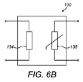
図5Aに示すように、デバイス10は、患者の皮膚内への薬剤の浸透を電気的に向上させるための、システム30を更に含む。図5Aに示す実施形態では、システム30は、第1の電極または上側の電極またはアノード31と、第2の電極または下側の電極またはカソード32と、上側および下側の電極31、32に連結されたDC電圧発生器33と、を含む。上側および下側の電極31、32は、短絡を回避するために、電気絶縁性材料によって分離されている。吸収性パッド15は、かかる絶縁材料の役割を果たし得る。別法として、例えば、吸収性パッド15が省略される実施形態では、例えばプラスチック製の、電気的に絶縁された穿孔されたシートを、上側および下側の電極31、32の間に配設してもよい。更なる代替形態では、上側および下側の電極31、32の間の電気絶縁は、例えばプラスチック製または電気絶縁特性を有するプラスチック材料で覆われた複数の絶縁ボール(insulating ball)によって生み出される。システム30は、上側および下側の電極31、32の間に、薬剤を患者の皮膚に向かって駆動または加速するための電界を生成するように構成されている。具体的には、システム30は、上側および下側の電極31、32の間に、薬剤を患者の皮膚に向かって駆動または加速するための、上側および下側の電極31、32の間における電流のパルスを生成するように構成されている。
As shown in FIG. 5A, the device 10 further includes a
上側および下側の電極31、32は、キャパシタを形成するように実質的に互いに平行に配設された、平行な金属製プレートの形態である。上側および下側の電極31、32は、吸収性パッド15の上流および下流にそれぞれ配設されている。別法として、図5Bに示すように、上側および下側の電極31、32は、吸収性パッド15の上流に配設されている。例えば、上側および下側の電極31、32は、投薬出口19b内に配設されている。上側および下側の電極31、32は透過性であり、これにより使用時に薬剤が上側および/または下側の電極31、32を通って吸収性パッド15に向かって流れるようになっている。例えば、上側および/または下側の電極31、32は、穿孔されたプレートまたは穴マスクの形態である。
The upper and
DC電圧発生器33は、上側および下側の電極31、32の間に電位差を生成するように構成される。図5Aに示す実施形態では、DC電圧発生器33は、デバイス10の使い捨ての部材29内に位置する。ただし、DC電圧発生器33は、デバイス10内の異なる場所に、例えば再利用可能な部材28内に位置することもできる。
The
上側の電極31および下側の電極32は、互いに対して、上側および下側の電極31、32の間の電界の強度が最適化されるように配置されている。生成される電解と、上側および下側の電極31、32の間の距離との間の関係は、以下のように定義される:

システム30は、上側の電極31と下側の電極32との間で高電圧および持続の短いパルスを生成するように構成されている。上側および下側の電極31、32の間の電位差は、好ましくは約50ボルトの範囲である。パルスの持続時間は、好ましくは約1秒以上である。
使用時、薬剤は、リザーバ12からマニホールド19内に入って投薬出口19bに向かい、上側および下側の電極31、32の間を流れる。薬剤は、例えば毛管力によって、上側および下側の電極31、32の間を流れる。上側および下側の電極31、32の間に生成されたパルス電界により、薬剤中の分子が、例えばデバイス10がインスリン送達デバイスである場合にはインスリン分子が、またはより一般的には薬剤中に存在する極性分子が、下側の電極32に向けておよび患者の皮膚に向けて加速される。この過程は電気穿孔法としても知られており、薬剤が患者の皮膚を通して最適に輸送されることを保証する。図5Bに示すように、上側および下側の電極31、32の間に生成された電界により、上側および下側の電極31、32の間に存在する空気の分子がイオン化される。生成されたイオンは、電界により下側の電極32に向けて加速される。これらのイオンにより皮膚に更に孔を開けることが可能になり、このことにより、皮膚を通した薬剤の浸透が更に向上する。薬剤を患者の皮膚に向けて更に加速するために、デバイス10内に、ファンなどの通風手段を設けることもできる。
In use, the medicament enters the manifold 19 from the
高電圧で持続の短いパルスを患者の皮膚に印加することにより、皮膚内への薬剤の分子および水性化合物の皮膚浸透を、効果的に向上させることが可能になる。例えば、電気穿孔法を介して利用可能な経皮経路の数は、イオン導入法を介して利用可能な経皮経路の数の500倍を超える。生成されたパルス電界により、皮膚の脂質二重層膜内に通路が作り出され、これにより、皮膚を通した薬剤の浸透がより容易になる。したがって、デバイス10により、患者の皮膚の透過性を高めることが可能になる。具体的には、デバイス10により、従来の経皮薬剤送達デバイスよりも大きな体積の薬剤を、皮膚を通して輸送することが可能になる。システム30によりまた、従来の経皮薬剤送達デバイスを用いた場合よりも大きな分子量の分子を、皮膚を通して輸送することも可能になる。特に、システム30とマイクロニードル16のアレイ17を組み合わせることにより、皮膚バリアをより容易に克服すること、およびしたがって、従来の薬剤送達デバイスを用いた場合よりも薬剤をより効率的に投与することが、可能になる。
By applying short pulses of high voltage and duration to the patient's skin, skin penetration of drug molecules and aqueous compounds into the skin can be effectively enhanced. For example, the number of percutaneous routes available via electroporation exceeds 500 times the number of percutaneous routes available via iontophoresis. The generated pulsed electric field creates a passage in the lipid bilayer membrane of the skin, which makes it easier for the drug to penetrate through the skin. Thus, the device 10 allows for increased permeability of the patient's skin. In particular, device 10 allows for a larger volume of drug to be transported through the skin than conventional transdermal drug delivery devices.
本発明の更なる実施形態に係る薬剤注射デバイス110が、図6Aに示されている。更なる実施形態は第1の実施形態に密接に対応しており、同様の構成要素には同様の参照符号が使用されている。第1の実施形態に対する違いを以下に記載する。
A
デバイス110は、患者の皮膚を通した薬剤の浸透を向上させるための、加熱システム130を含む。図6Aに示す実施形態では、加熱システム130は、患者の皮膚を加熱するように構成された加熱要素134を含む。加熱要素134は透過性であり、使用時に薬剤が加熱要素134を通り患者の皮膚に向かって流れるようになっている。例えば、加熱要素134は、穿孔されたフォイルの形態である。変形形態では、加熱要素134はコイル状の抵抗の形態である。加熱要素134は、好ましくは電気的に絶縁されている。加熱要素134は、吸収性パッド15の上流の、投薬出口19bのところに配設される。加熱要素134は、吸収性パッド15と平行に配設されている。好ましくは、加熱要素134は、吸収性パッド15が効率的にかつ均一に加熱されるように、吸収性パッド15の長さの半分を超える距離に沿って延在する。
システム130は、加熱要素134の温度を制御するための熱制御装置135を含む。熱制御装置135は温度センサを含む。温度センサは例えば、NTCサーミスタ、PTCサーミスタ、半導体、またはゼーベック効果で機能する熱電対である。
使用時、加熱システム130は、薬剤および注射部位を加熱する。この加熱により、注射部位の近くで患者の体内の血流を増加させることができ、このことにより薬剤拡散作用が向上する。この加熱により注射部位の領域内の微小循環が向上し、この結果、患者の体内への薬剤移送が促進される。
In use,
使用時、加熱要素134の温度は、薬剤拡散作用を効率的に向上させるのに十分な程度に高くあるべきである。しかしながらこの温度は高過ぎるべきではなく、その理由は、薬剤吸収の効率を低下させ皮膚からのデバイス110の脱離を引き起こし得る、皮膚の発汗を回避するためである。使用時、加熱要素134の温度は好ましくは、患者の皮膚の温度よりも約5度高い。加熱要素134をそのような温度に維持するために、デバイス110内に温度センサを設けてもよい。別法として、加熱要素134の温度が部屋の温度よりも高い、例えば部屋の温度よりも約5度高い値に維持されるように、デバイス110内に、薬剤送達が行われる部屋の温度を測定するためのセンサを設けてもよい。
In use, the temperature of the
本発明の更なる実施形態に係る薬剤注射デバイス210が、図7に示されている。更なる実施形態は第1の実施形態に密接に対応しており、同様の構成要素には同様の参照符号が使用されている。第1の実施形態に対する違いを以下に記載する。
A
デバイス210は、患者の皮膚内への薬剤の浸透を化学的に向上させるための、システム230を含む。図7に示す実施形態では、システム230は、患者に補助剤(support agent)または開孔剤(pore opener)または化学物質浸透促進剤を送達するように構成されている。図7に示すように、システム230は、患者の皮膚内への薬剤送達の前に化学物質浸透促進剤を薬剤に混合するための機構を含む。機構は、化学物質浸透促進剤を収納するためのリザーバ236と、化学物質浸透促進剤が薬剤に接触する場所であるマニホールド19内に化学物質浸透促進剤を圧送するための、ポンプ237と、を含む。
化学物質浸透促進剤は、例えばジメチルスルホキシド(DMSO)である。薬剤をDMSOと混合することにより、皮膚を通した薬剤吸収を効率的に改善することが可能になる。変形形態では、薬剤送達の前に、エタノールなどのアルコールを薬剤に加えることができる。更なる変形形態では、薬剤が患者の皮膚のpHよりも低いpHを有するように薬剤のpH値を下げるために、薬剤に溶液を加えてもよい。例えば、生理食塩水を使用してもよい。もたらされる薬剤と皮膚との間のpH勾配により、結果的に、皮膚を通るように薬剤を駆動して薬剤が効率的に吸収されることを保証する、化学的な力が生じる。更なる代替形態では、皮膚の透過性を化学的に高めるために、脂肪物質などの他の物質または尿素を、薬剤に加えることもできる。化学物質浸透促進剤は、送達される薬剤に応じて選択される。 The chemical penetration enhancer is, for example, dimethyl sulfoxide (DMSO). Mixing the drug with DMSO allows for efficient improvement of drug absorption through the skin. In a variation, an alcohol, such as ethanol, can be added to the drug prior to drug delivery. In a further variation, a solution may be added to the drug to reduce the pH value of the drug so that the drug has a pH lower than the pH of the patient's skin. For example, physiological saline may be used. The resulting pH gradient between the drug and the skin results in a chemical force that drives the drug through the skin and ensures that the drug is efficiently absorbed. In a further alternative, other substances such as fatty substances or urea can be added to the medicament to chemically increase the permeability of the skin. The chemical penetration enhancer is selected depending on the drug to be delivered.
1つの実施形態では、薬剤は、患者の皮膚および身体における塩濃度が液体薬剤における塩濃度よりも大きいことを保証するための作用剤と混合され、この結果、患者の皮膚と薬剤との間の塩濃度の勾配によって生み出される浸透圧により、薬剤は患者の皮膚に向かって引っ張られるようになる。 In one embodiment, the medicament is mixed with an agent to ensure that the salt concentration in the patient's skin and body is greater than the salt concentration in the liquid medicament, such that the salt between the patient's skin and the medicament is The osmotic pressure created by the salt concentration gradient causes the drug to be pulled toward the patient's skin.
別法として、または加えて、化学物質浸透促進剤を、デバイス210の底面または皮膚取り付け面に提供してもよい。底面は例えば、化学物質浸透促進剤の層を含む。1つの実施形態では、底面は水性物質の層を含む。皮膚表面にある水の量を増やすことにより、皮膚表面を湿らせること、およびこの結果注射部位にある皮膚の孔を開くことが可能になり、このことにより皮膚の透過性が向上する。別法として、デバイス210の底面に油性物質の層を設けてもよい。
Alternatively, or in addition, a chemical penetration enhancer may be provided on the bottom surface or skin attachment surface of
用語「薬物」または「薬剤」は、本明細書において同意語として使用され、1つまたはそれ以上の医薬品有効成分または薬学的に許容されるその塩もしくは溶媒和物と、場合により、薬学的に許容される担体とを含む医薬製剤を示す。医薬品有効成分(「API」)とは、最も広範な言い方で、ヒトまたは動物に生物学的影響を及ぼす化学構造のことである。薬理学では、薬物または薬剤が、疾患の処置、治療、予防、または診断に使用され、またはそれとは別に、身体的または精神的健康を向上させるために使用される。薬物または薬剤は、限られた継続期間、または慢性疾患では定期的に、使用される。 The terms “drug” or “drug” are used synonymously herein and may include one or more active pharmaceutical ingredients or pharmaceutically acceptable salts or solvates thereof, optionally 1 shows a pharmaceutical formulation comprising an acceptable carrier. An active pharmaceutical ingredient ("API"), in its broadest terms, refers to a chemical structure that has a biological effect on a human or animal. In pharmacology, drugs or drugs are used to treat, treat, prevent, or diagnose a disease, or, alternatively, to improve physical or mental health. Drugs or drugs are used for a limited duration or regularly in chronic diseases.
以下に説明されるように、薬物または薬剤は、1つまたはそれ以上の疾患を処置するための、様々なタイプの製剤の少なくとも1つのAPI、またはその組み合わせを含むことができる。APIの例としては、分子量が500Da以下である低分子;ポリペプチド、ペプチド、およびタンパク質(例えばホルモン、成長因子、抗体、抗体フラグメント、および酵素);炭水化物および多糖類;ならびに核酸、二本鎖または一本鎖DNA(裸およびcDNAを含む)、RNA、アンチセンスDNAおよびRNAなどのアンチセンス核酸、低分子干渉RNA(siRNA)、リボザイム、遺伝子、およびオリゴヌクレオチドが含まれ得る。核酸は、ベクター、プラスミド、またはリポソームなどの分子送達システムに組み込まれる。1つまたはそれ以上の薬物の混合物もまた企図される。 As described below, the drug or agent can include at least one API of various types of formulations, or combinations thereof, for treating one or more diseases. Examples of APIs are small molecules having a molecular weight of 500 Da or less; polypeptides, peptides, and proteins (eg, hormones, growth factors, antibodies, antibody fragments, and enzymes); carbohydrates and polysaccharides; and nucleic acids, double-stranded or Single-stranded DNA (including naked and cDNA), RNA, antisense nucleic acids such as antisense DNA and RNA, small interfering RNA (siRNA), ribozymes, genes, and oligonucleotides can be included. Nucleic acids are incorporated into molecular delivery systems such as vectors, plasmids, or liposomes. Mixtures of one or more drugs are also contemplated.
用語「薬物送達デバイス」は、薬物または薬剤をヒトまたは動物の体内に投薬するように構成されたあらゆるタイプのデバイスまたはシステムを包含するものである。それだけには限らないが、薬物送達デバイスは、注射デバイス(例えばペン型注射器、自動注射器、大容量デバイス、ポンプ、潅流システム、または眼内、皮下、筋肉内、もしくは血管内送達にあわせて構成された他のデバイス)、皮膚パッチ(例えば、浸透圧性、化学的)、吸入器(例えば鼻用または肺用)、埋め込み型デバイス(例えば、薬物またはAPIコーティングされたステント、カプセル)、または胃腸管用の供給システムとすることができる。 The term "drug delivery device" is intended to encompass any type of device or system configured to dispense a drug or drug into a human or animal body. Without limitation, the drug delivery device may be configured for injection devices (e.g., pen injectors, auto-injectors, large volume devices, pumps, perfusion systems, or intraocular, subcutaneous, intramuscular, or intravascular delivery). Supplies for other devices), skin patches (eg, osmotic, chemical), inhalers (eg, nasal or pulmonary), implantable devices (eg, drug or API coated stents, capsules), or gastrointestinal tract System.
薬物または薬剤は、薬物送達デバイスで使用するように適用された主要パッケージまたは「薬物容器」内に含まれる。薬物容器は、例えば、カートリッジ、リザーバ、または1つもしくはそれ以上の薬物の保存(例えば短期または長期保存)に適したチャンバを提供するように構成された他の固体もしくは可撓性の容器とすることができる。例えば、場合によって、チャンバは、少なくとも1日(例えば1日から少なくとも30日まで)の間薬物を収納するように設計される。場合によって、チャンバは、約1ヶ月から約2年の間薬物を保存するように設計される。保存は、室温(例えば約20℃)または冷蔵温度(例えば約−4℃から約4℃まで)で行うことができる。場合によって、薬物容器は、投与予定の医薬製剤の2つまたはそれ以上の成分(例えばAPIおよび希釈剤、または2つの異なるタイプの薬物)を別々に、各チャンバに1つずつ保存するように構成された二重チャンバカートリッジとすることができ、またはこれを含むことができる。そのような場合、二重チャンバカートリッジの2つのチャンバは、ヒトまたは動物の体内に投薬する前、および/または投薬中に2つまたはそれ以上の成分間で混合することを可能にするように構成される。例えば、2つのチャンバは、これらが(例えば2つのチャンバ間の導管によって)互いに流体連通し、所望の場合、投薬の前にユーザによって2つの成分を混合することを可能にするように構成される。代替的に、またはこれに加えて、2つのチャンバは、成分がヒトまたは動物の体内に投薬されているときに混合することを可能にするように構成される。 The drug or drug is contained within a main package or "drug container" adapted for use in a drug delivery device. The drug container may be, for example, a cartridge, a reservoir, or other solid or flexible container configured to provide a chamber suitable for storing one or more drugs (eg, short or long term storage). be able to. For example, in some cases, the chamber is designed to contain the drug for at least one day (eg, from one day to at least 30 days). In some cases, the chamber is designed to store the drug for about one month to about two years. Storage can be performed at room temperature (eg, about 20 ° C.) or at refrigerated temperatures (eg, about −4 ° C. to about 4 ° C.). In some cases, the drug container is configured to store two or more components of the pharmaceutical formulation to be administered (eg, API and diluent, or two different types of drugs) separately, one in each chamber. And may include or include a dual chamber cartridge. In such cases, the two chambers of the dual-chamber cartridge are configured to allow mixing between the two or more components prior to and / or during dosing into the human or animal body. Is done. For example, the two chambers are configured such that they are in fluid communication with each other (eg, by a conduit between the two chambers) and, if desired, allow the user to mix the two components prior to dosing. . Alternatively or additionally, the two chambers are configured to allow the components to mix when being dispensed into a human or animal body.
本明細書において説明される薬物送達デバイス内に含まれる薬物または薬剤は、数多くの異なるタイプの医学的障害の処置および/または予防に使用される。障害の例としては、例えば、糖尿病、または糖尿病性網膜症などの糖尿病に伴う合併症、深部静脈血栓塞栓症または肺血栓塞栓症などの血栓塞栓症が含まれる。障害の別の例としては、急性冠症候群(ACS)、狭心症、心筋梗塞、がん、黄斑変性症、炎症、枯草熱、アテローム性動脈硬化症および/または関節リウマチがある。APIおよび薬物の例としては、例えば、それだけには限らないが、ハンドブックのRote Liste 2014、主グループ12(抗糖尿病薬物)または主グループ86(腫瘍薬物)、およびMerck Index、第15版などに記載されているものがある。 The drugs or agents contained within the drug delivery devices described herein are used for the treatment and / or prevention of many different types of medical disorders. Examples of disorders include, for example, diabetes or diabetic complications such as diabetic retinopathy, thromboembolism such as deep vein thromboembolism or pulmonary thromboembolism. Another example of a disorder is acute coronary syndrome (ACS), angina, myocardial infarction, cancer, macular degeneration, inflammation, hay fever, atherosclerosis and / or rheumatoid arthritis. Examples of APIs and drugs include, but are not limited to, those described in the Handbook for Rot List 2014, Main Group 12 (anti-diabetic drugs) or Main Group 86 (tumor drugs), and Merck Index, 15th Edition. There are things that are.
1型もしくは2型の糖尿病、または1型もしくは2型の糖尿病に伴う合併症の処置および/または予防のためのAPIの例としては、インスリン、例えばヒトインスリン、またはヒトインスリン類似体もしくは誘導体、グルカゴン様ペプチド(GLP−1)、GLP−1類似体もしくはGLP−1受容体アゴニスト、またはその類似体もしくは誘導体、ジペプチジルペプチダーゼ−4(DPP4)阻害剤、または薬学的に許容されるその塩もしくは溶媒和物、またはそれらの任意の混合物が含まれる。本明細書において使用される用語「類似体」および「誘導体」は、元の物質と構造的に十分に類似しており、それによって同様の機能または活性(例えば治療効果性)を有することができる任意の物質を指す。特に、用語「類似体」は、天然のペプチドの構造、例えばヒトのインスリンの構造から、天然のペプチド中に見出される少なくとも1つのアミノ酸残基を欠失させるおよび/もしくは交換することによって、ならびに/または少なくとも1つのアミノ酸残基を付加することによって式上で得られる分子構造を有するポリペプチドを指す。付加および/または交換されるアミノ酸残基は、コード可能なアミノ酸残基、または他の天然の残基もしくは完全に合成によるアミノ酸残基とすることができる。インスリン類似体は「インスリン受容体リガンド」とも呼ばれる。特に、用語「誘導体」は、1つまたはそれ以上の有機置換基(例えば、脂肪酸)が1つまたはそれ以上のアミノ酸に結合している、天然のペプチドの構造、例えばヒトのインスリンの構造から式上で得られる分子構造を有するポリペプチドを指す。場合により、天然のペプチド中に見出される1つまたはそれ以上のアミノ酸が、欠失され、かつ/もしくはコード不可能なアミノ酸を含む他のアミノ酸によって置換されていてもよく、または、コード不可能なアミノ酸を含むアミノ酸が、天然のペプチドに付加されていてもよい。
Examples of APIs for the treatment and / or prevention of
インスリン類似体の例としては、Gly(A21),Arg(B31),Arg(B32)ヒトインスリン(インスリングラルギン);Lys(B3),Glu(B29)ヒトインスリン(インスリングルリジン);Lys(B28),Pro(B29)ヒトインスリン(インスリンリスプロ);Asp(B28)ヒトインスリン(インスリンアスパルト);B28位におけるプロリンがAsp、Lys、Leu、Val、またはAlaで置き換えられており、B29位において、LysがProで置換されているヒトインスリン;Ala(B26)ヒトインスリン;Des(B28−B30)ヒトインスリン;Des(B27)ヒトインスリンおよびDes(B30)ヒトインスリンがある。 Examples of insulin analogues include Gly (A21), Arg (B31), Arg (B32) human insulin (insulin glargine); Lys (B3), Glu (B29) human insulin (insulin glulisine); Lys (B28) , Pro (B29) human insulin (insulin lispro); Asp (B28) human insulin (insulin aspart); the proline at position B28 has been replaced with Asp, Lys, Leu, Val, or Ala, and at position B29 Lys Ala (B26) human insulin; Des (B28-B30) human insulin; Des (B27) human insulin and Des (B30) human insulin.
インスリン誘導体の例としては、例えば、B29−N−ミリストイル−des(B30)ヒトインスリン;Lys(B29)(N−テトラデカノイル)−des(B30)ヒトインスリン(インスリンデテミル、Levemir(登録商標))、B29−N−パルミトイル−des(B30)ヒトインスリン;B29−N−ミリストイルヒトインスリン;B29−N−パルミトイルヒトインスリン;B28−N−ミリストイルLysB28ProB29ヒトインスリン;B28−N−パルミトイル−LysB28ProB29ヒトインスリン;B30−N−ミリストイル−ThrB29LysB30ヒトインスリン;B30−N−パルミトイル−ThrB29LysB30ヒトインスリン;B29−N−(N−パルミトイル−γ−グルタミル)−des(B30)ヒトインスリン;B29−N−ω−カルボキシヘプタデカノイル−γ−L−グルタミル−des(B30)ヒトインスリン(インスリンデグルデク、Tresiba(登録商標))、B29−N−(N−リトコリル−γ−グルタミル)−des(B30)ヒトインスリン;B29−N−(ω−カルボキシヘプタデカノイル)−des(B30)ヒトインスリン、およびB29−N−(ω−カルボキシヘプタデカノイル)ヒトインスリンがある。 Examples of insulin derivatives include, for example, B29-N-myristoyl-des (B30) human insulin; Lys (B29) (N-tetradecanoyl) -des (B30) human insulin (insulin detemil, Levemir®) , B29-N-palmitoyl-des (B30) human insulin; B29-N-myristoyl human insulin; B29-N-palmitoyl human insulin; B28-N-myristoyl LysB28ProB29 human insulin; B28-N-palmitoyl-LysB28ProB29 human insulin; -N-myristoyl-ThrB29LysB30 human insulin; B30-N-palmitoyl-ThrB29LysB30 human insulin; B29-N- (N-palmitoyl-γ-glutamyl -Des (B30) human insulin; B29-N-ω-carboxyheptadecanoyl-γ-L-glutamyl-des (B30) human insulin (insulin degludec, Tresiba®), B29-N- (N -Litcholyl-γ-glutamyl) -des (B30) human insulin; B29-N- (ω-carboxyheptadecanoyl) -des (B30) human insulin, and B29-N- (ω-carboxyheptadecanoyl) human insulin. There is.
GLP−1、GLP−1類似体およびGLP−1受容体アゴニストの例としては、例えば、リキシセナチド(Lyxumia(登録商標)、エキセナチド(エキセンディン−4、Dyetta(登録商標)、Bydureon(登録商標)、アメリカドクトカゲの唾液腺によって産生される39アミノ酸ペプチド)、リラグルチド(Victoza(登録商標))、セマグルチド、タスポグルチド、アルビグルチド(Syncria(登録商標))、デュラグルチド(Trulicity(登録商標))、rエキセンディン−4、CJC−1134−PC、PB−1023、TTP−054、ラングレナチド/HM−11260C、CM−3、GLP−1エリゲン(Eligen)、ORMD−0901、NN−9924、NN−9926、NN−9927、ノデキセン(Nodexen)、ビアドール(Viador)−GLP−1、CVX−096、ZYOG−1、ZYD−1、GSK−2374697、DA−3091、MAR−701、MAR709、ZP−2929、ZP−3022、TT−401、BHM−034、MOD−6030、CAM−2036、DA−15864、ARI−2651、ARI−2255、エキセナチド−XTENおよびグルカゴン−Xtenがある。 Examples of GLP-1, GLP-1 analogs and GLP-1 receptor agonists include, for example, lixisenatide (Lyxumia®, exenatide (Exendin-4, Dyetta®, Bydureon®, A 39-amino acid peptide produced by the salivary glands of the American lizard), liraglutide (Victoza®), semaglutide, taspoglutide, albiglutide (Syncria®), duraglutide (Trlicity®), rExendin-4, CJC-1134-PC, PB-1023, TTP-054, Langrenatide / HM-11260C, CM-3, GLP-1 Eligen, ORMD-0901, NN-9924, NN-9926, N-9927, Nodexen, Viador-GLP-1, CVX-096, ZYOG-1, ZYD-1, GSK-2374697, DA-3091, MAR-701, MAR709, ZP-2929, ZP- 3022, TT-401, BHM-034, MOD-6030, CAM-2036, DA-15864, ARI-2651, ARI-2255, exenatide-XTEN and glucagon-Xten.
オリゴヌクレオチドの例としては、例えば:家族性高コレステロール血症の処置のためのコレステロール低下アンチセンス治療薬である、ミポメルセンナトリウム(Kynamro(登録商標))がある。 Examples of oligonucleotides include, for example: mipomersen sodium (Kynamro®), a cholesterol-lowering antisense therapeutic for the treatment of familial hypercholesterolemia.
DPP4阻害剤の例としては、ビルダグリプチン、シタグリプチン、デナグリプチン、サキサグリプチン、ベルベリンがある。 Examples of DPP4 inhibitors include vildagliptin, sitagliptin, denagliptin, saxagliptin, berberine.
ホルモンの例としては、ゴナドトロピン(フォリトロピン、ルトロピン、コリオンゴナドトロピン、メノトロピン)、ソマトロピン(ソマトロピン)、デスモプレシン、テルリプレシン、ゴナドレリン、トリプトレリン、ロイプロレリン、ブセレリン、ナファレリン、およびゴセレリンなどの、脳下垂体ホルモンまたは視床下部ホルモンまたは調節性活性ペプチドおよびそれらのアンタゴニストが含まれる。 Examples of hormones include pituitary hormones or thalamus, such as gonadotropin (folitropin, lutropin, corion gonadotropin, menotropin), somatropin (somatropin), desmopressin, terlipressin, gonadorelin, triptorelin, leuprorelin, buserelin, nafarelin, and goserelin. Includes lower hormone or regulatory active peptides and their antagonists.
多糖類の例としては、グルコサミノグリカン、ヒアルロン酸、ヘパリン、低分子量ヘパリン、もしくは超低分子量ヘパリン、またはそれらの誘導体、または上述の多糖類の硫酸化形態、例えば、ポリ硫酸化形態、および/または、薬学的に許容されるそれらの塩が含まれる。ポリ硫酸化低分子量ヘパリンの薬学的に許容される塩の例としては、エノキサパリンナトリウムがある。ヒアルロン酸誘導体の例としては、ハイランG−F20(Synvisc(登録商標))、ヒアルロン酸ナトリウムがある。 Examples of polysaccharides include glucosaminoglycan, hyaluronic acid, heparin, low molecular weight heparin, or ultra low molecular weight heparin, or derivatives thereof, or sulfated forms of the above-described polysaccharides, such as polysulfated forms, and And / or pharmaceutically acceptable salts thereof. An example of a pharmaceutically acceptable salt of a polysulfated low molecular weight heparin is enoxaparin sodium. Examples of hyaluronic acid derivatives include Hylan G-F20 (Synvisc®), sodium hyaluronate.
本明細書において使用する用語「抗体」は、免疫グロブリン分子またはその抗原結合部分を指す。免疫グロブリン分子の抗原結合部分の例には、抗原を結合する能力を保持するF(ab)およびF(ab’)2フラグメントが含まれる。抗体は、ポリクローナル、モノクローナル、組換え型、キメラ型、非免疫型またはヒト化、完全ヒト型、非ヒト型(例えばネズミ)、または一本鎖抗体とすることができる。いくつかの実施形態では、抗体はエフェクター機能を有し、補体を固定することができる。いくつかの実施形態では、抗体は、Fc受容体と結合する能力が低く、または結合することはできない。例えば、抗体は、アイソタイプもしくはサブタイプ、抗体フラグメントまたは変異体とすることができ、これはFc受容体との結合を支持せず、例えば、突然変異した、または欠失したFc受容体結合領域を有する。用語の抗体はまた、四価二重特異性タンデム免疫グロブリン(TBTI)および/または交差結合領域の配向性を有する二重可変領域抗体様結合タンパク質(CODV)に基づく抗体結合分子を含む。 As used herein, the term "antibody" refers to an immunoglobulin molecule or an antigen-binding portion thereof. Examples of antigen-binding portions of an immunoglobulin molecule include F (ab) and F (ab ') 2 fragments that retain the ability to bind antigen. Antibodies can be polyclonal, monoclonal, recombinant, chimeric, non-immunized or humanized, fully human, non-human (eg, murine), or single-chain. In some embodiments, the antibodies have effector functions and can fix complement. In some embodiments, the antibody has reduced or no ability to bind to the Fc receptor. For example, an antibody can be an isotype or subtype, an antibody fragment or a variant that does not support binding to an Fc receptor, eg, has a mutated or deleted Fc receptor binding region. Have. The term antibody also includes antibody binding molecules based on a tetravalent bispecific tandem immunoglobulin (TBTI) and / or a dual variable region antibody-like binding protein (CODV) with cross-linking region orientation.
用語「フラグメント」または「抗体フラグメント」は、全長抗体ポリペプチドを含まないが、抗原と結合することができる全長抗体ポリペプチドの少なくとも一部分を依然として含む、抗体ポリペプチド分子(例えば、抗体重鎖および/または軽鎖ポリペプチド)由来のポリペプチドを指す。抗体フラグメントは、全長抗体ポリペプチドの切断された部分を含むことができるが、この用語はそのような切断されたフラグメントに限定されない。本発明に有用である抗体フラグメントは、例えば、Fabフラグメント、F(ab’)2フラグメント、scFv(一本鎖Fv)フラグメント、直鎖抗体、単一特異性抗体フラグメント、または二重特異性、三重特異性、四重特異性および多重特異性抗体(例えば、ダイアボディ、トリアボディ、テトラボディ)などの多重特異性抗体フラグメント、一価抗体フラグメント、または二価、三価、四価および多価抗体などの多価抗体フラグメント、ミニボディ、キレート組換え抗体、トリボディまたはバイボディ、イントラボディ、ナノボディ、小モジュラー免疫薬(SMIP)、結合ドメイン免疫グロブリン融合タンパク質、ラクダ化抗体、およびVHH含有抗体を含む。抗原結合抗体フラグメントの更なる例が当技術分野で知られている。 The term “fragment” or “antibody fragment” does not include a full-length antibody polypeptide, but still comprises at least a portion of a full-length antibody polypeptide capable of binding antigen (eg, an antibody heavy chain and / or antibody heavy chain). Or light chain polypeptide). An antibody fragment can include a truncated portion of a full-length antibody polypeptide, but the term is not limited to such truncated fragments. Antibody fragments useful in the present invention include, for example, Fab fragments, F (ab ') 2 fragments, scFv (single-chain Fv) fragments, linear antibodies, monospecific antibody fragments, or bispecific, trispecific, Multispecific antibody fragments, such as specificity, tetraspecific and multispecific antibodies (eg, diabodies, triabodies, tetrabodies), monovalent antibody fragments, or bivalent, trivalent, tetravalent and multivalent antibodies Multivalent antibody fragments, minibodies, chelating recombinant antibodies, tribodies or bibodies, intrabodies, nanobodies, small modular immunopharmaceuticals (SMIP), binding domain immunoglobulin fusion proteins, camelized antibodies, and VHH-containing antibodies. Further examples of antigen binding antibody fragments are known in the art.
用語「相補性決定領域」または「CDR」は、特異的抗原認識を仲介する役割を主に担う重鎖および軽鎖両方のポリペプチドの可変領域内の短いポリペプチド配列を指す。用語「フレームワーク領域」は、CDR配列ではなく、CDR配列の正しい位置決めを維持して抗原結合を可能にする役割を主に担う重鎖および軽鎖両方のポリペプチドの可変領域内のアミノ酸配列を指す。フレームワーク領域自体は、通常、当技術分野で知られているように、抗原結合に直接的に関与しないが、特定の抗体のフレームワーク領域内の特定の残基が、抗原結合に直接的に関与することができ、またはCDR内の1つまたはそれ以上のアミノ酸が抗原と相互作用する能力に影響を与えることができる。 The term "complementarity determining region" or "CDR" refers to a short polypeptide sequence within the variable regions of both heavy and light chain polypeptides that is primarily responsible for mediating specific antigen recognition. The term "framework region" refers to the amino acid sequence within the variable region of both the heavy and light chain polypeptides, not the CDR sequences, but which is primarily responsible for maintaining the correct positioning of the CDR sequences and allowing antigen binding. Point. The framework regions themselves are not normally involved in antigen binding, as is known in the art, but certain residues within the framework regions of a particular antibody may be directly involved in antigen binding. Can be involved, or can affect the ability of one or more amino acids in the CDR to interact with the antigen.
抗体の例としては、アンチPCSK−9mAb(例えばアリロクマブ)、アンチIL−6mAb(例えばサリルマブ)、およびアンチIL−4mAb(例えばデュピルマブ)がある。 Examples of antibodies include anti-PCSK-9 mAb (eg, arilocumab), anti-IL-6 mAb (eg, salilumab), and anti-IL-4 mAb (eg, dupilumab).
本明細書において説明される任意のAPIの薬学的に許容される塩もまた、薬物送達デバイスにおける薬物または薬剤の使用に企図される。薬学的に許容される塩は、例えば酸付加塩および塩基性塩である。 Pharmaceutically acceptable salts of any of the APIs described herein are also contemplated for use with a drug or agent in a drug delivery device. Pharmaceutically acceptable salts are, for example, acid addition salts and basic salts.
本明細書に記載するAPI、配合、装置、方法、システム、および実施形態の様々な構成要素の修正(追加および/または削除)を、本発明の最大限の範囲および精神から逸脱することなく行うことができ、そこにはかかる修正形態およびそのありとあらゆる均等物が包含されていることを、当業者は理解するであろう。 Modifications (additions and / or deletions) of various components of the APIs, formulations, devices, methods, systems, and embodiments described herein may be made without departing from the full scope and spirit of the invention. Those skilled in the art will appreciate that such modifications and all their equivalents may be included therein.
Claims (15)
患者に薬剤を送達するための少なくとも1つのマイクロニードル(16)と;
患者の皮膚内への薬剤の浸透を向上させるように構成されたシステム(30、130、230)と、を含む、前記薬剤送達デバイス。 A drug delivery device (10, 110, 210) comprising:
At least one microneedle (16) for delivering a drug to the patient;
A system (30, 130, 230) configured to enhance penetration of the drug into the skin of the patient.
Applications Claiming Priority (3)
| Application Number | Priority Date | Filing Date | Title |
|---|---|---|---|
| EP16206617.9A EP3338853A1 (en) | 2016-12-23 | 2016-12-23 | Medicament delivery device |
| EP16206617.9 | 2016-12-23 | ||
| PCT/EP2017/084146 WO2018115312A1 (en) | 2016-12-23 | 2017-12-21 | Medicament delivery device |
Publications (2)
| Publication Number | Publication Date |
|---|---|
| JP2020503112A true JP2020503112A (en) | 2020-01-30 |
| JP7018061B2 JP7018061B2 (en) | 2022-02-09 |
Family
ID=57609754
Family Applications (1)
| Application Number | Title | Priority Date | Filing Date |
|---|---|---|---|
| JP2019534299A Active JP7018061B2 (en) | 2016-12-23 | 2017-12-21 | Drug delivery device |
Country Status (5)
| Country | Link |
|---|---|
| US (2) | US11666739B2 (en) |
| EP (2) | EP3338853A1 (en) |
| JP (1) | JP7018061B2 (en) |
| CN (1) | CN110087723A (en) |
| WO (1) | WO2018115312A1 (en) |
Cited By (1)
| Publication number | Priority date | Publication date | Assignee | Title |
|---|---|---|---|---|
| WO2023224198A1 (en) * | 2022-05-19 | 2023-11-23 | 주식회사 밀알 | Dispenser for electroporation comprising disposable cartridge |
Families Citing this family (5)
| Publication number | Priority date | Publication date | Assignee | Title |
|---|---|---|---|---|
| JP7385237B2 (en) * | 2019-04-09 | 2023-11-22 | 株式会社オイコス | skin management device |
| CN112402733B (en) * | 2020-02-26 | 2022-07-15 | 苏州喜全软件科技有限公司 | Insulin pump based on current pulse osmosis |
| DE102020129916A1 (en) * | 2020-11-12 | 2022-05-12 | Lts Lohmann Therapie-Systeme Ag. | Interdermal drug delivery system |
| CN113813505B (en) * | 2021-09-15 | 2022-03-15 | 久心医疗科技(苏州)有限公司 | Dry-type defibrillation electrode |
| CN118217522A (en) * | 2022-12-20 | 2024-06-21 | 苏州悦肤达医疗科技有限公司 | Medical device and preparation method thereof |
Citations (5)
| Publication number | Priority date | Publication date | Assignee | Title |
|---|---|---|---|---|
| JP2002523195A (en) * | 1998-08-31 | 2002-07-30 | ジョンソン・アンド・ジョンソン・コンシューマー・カンパニーズ・インコーポレイテッド | Electronic transport device with blade |
| JP2004505652A (en) * | 1999-06-08 | 2004-02-26 | アルテア テクノロジーズ,インコーポレイティド | Apparatus for microporation of biological membranes using thin-film tissue interface devices and methods therefor |
| JP2008543872A (en) * | 2005-06-17 | 2008-12-04 | アルテア セラピューティクス コーポレイション | Permeate delivery system and method of use |
| JP2009508595A (en) * | 2005-09-19 | 2009-03-05 | トランスポート・ファーマシューティカルズ・インコーポレーテッド | Electrokinetic delivery system and method |
| JP2010253199A (en) * | 2009-04-28 | 2010-11-11 | Toppan Forms Co Ltd | Device for electroporation |
Family Cites Families (16)
| Publication number | Priority date | Publication date | Assignee | Title |
|---|---|---|---|---|
| US20020114827A1 (en) | 1995-07-28 | 2002-08-22 | Jie Zhang | Methods and apparatus for improved administration of analgesics |
| US6835184B1 (en) * | 1999-09-24 | 2004-12-28 | Becton, Dickinson And Company | Method and device for abrading skin |
| US7127284B2 (en) * | 2001-06-11 | 2006-10-24 | Mercator Medsystems, Inc. | Electroporation microneedle and methods for its use |
| US6836678B2 (en) | 2003-02-13 | 2004-12-28 | Xiang Zheng Tu | Non-invasive blood glucose monitor |
| CN1287872C (en) | 2003-10-21 | 2006-12-06 | 中国科学院电子学研究所 | Air bag controlled micro medicine conveying executor |
| TWI259091B (en) * | 2004-07-09 | 2006-08-01 | Nat Univ Chung Cheng | Electrical energy assisting device for transdermal patch |
| US20070276318A1 (en) * | 2006-05-26 | 2007-11-29 | Mit, Llp | Iontosonic-microneedle applicator apparatus and methods |
| CN101715354B (en) | 2007-03-19 | 2013-12-04 | 茵苏莱恩医药有限公司 | Method and device for drug delivery |
| CA2760467A1 (en) | 2009-05-08 | 2010-11-11 | Isis Biopolymer, Inc. | Iontophoretic device with improved counterelectrode |
| CN102844072A (en) | 2010-01-29 | 2012-12-26 | 优比欧迈德有限公司 | Micro needle and micro needle device |
| JP2011224153A (en) * | 2010-04-20 | 2011-11-10 | Wataru Watanabe | Medicine sheet |
| CN103418081B (en) | 2012-05-24 | 2014-10-22 | 纳米新能源(唐山)有限责任公司 | System for drug iontophoresis driven by triboelectric field |
| CN104096311B (en) * | 2014-07-01 | 2016-03-23 | 中山大学 | Based on the manufacture method of the microneedle array of high voltage electric field |
| CN204246683U (en) * | 2014-10-31 | 2015-04-08 | 厦门微科格瑞生物科技有限公司 | Intellectual drug import system can be worn |
| CN105816952A (en) | 2016-01-05 | 2016-08-03 | 中国人民解放军第二军医大学 | Novel electret microneedle transdermal drug delivery system |
| CN106063971A (en) * | 2016-05-24 | 2016-11-02 | 中山大学 | Percutaneous electric osmose doser based on metal porous microneedle array and medication |
-
2016
- 2016-12-23 EP EP16206617.9A patent/EP3338853A1/en not_active Withdrawn
-
2017
- 2017-12-21 EP EP17828907.0A patent/EP3558438B1/en active Active
- 2017-12-21 JP JP2019534299A patent/JP7018061B2/en active Active
- 2017-12-21 WO PCT/EP2017/084146 patent/WO2018115312A1/en unknown
- 2017-12-21 CN CN201780079261.9A patent/CN110087723A/en active Pending
- 2017-12-21 US US16/472,263 patent/US11666739B2/en active Active
-
2023
- 2023-04-24 US US18/305,751 patent/US20230248954A1/en active Pending
Patent Citations (5)
| Publication number | Priority date | Publication date | Assignee | Title |
|---|---|---|---|---|
| JP2002523195A (en) * | 1998-08-31 | 2002-07-30 | ジョンソン・アンド・ジョンソン・コンシューマー・カンパニーズ・インコーポレイテッド | Electronic transport device with blade |
| JP2004505652A (en) * | 1999-06-08 | 2004-02-26 | アルテア テクノロジーズ,インコーポレイティド | Apparatus for microporation of biological membranes using thin-film tissue interface devices and methods therefor |
| JP2008543872A (en) * | 2005-06-17 | 2008-12-04 | アルテア セラピューティクス コーポレイション | Permeate delivery system and method of use |
| JP2009508595A (en) * | 2005-09-19 | 2009-03-05 | トランスポート・ファーマシューティカルズ・インコーポレーテッド | Electrokinetic delivery system and method |
| JP2010253199A (en) * | 2009-04-28 | 2010-11-11 | Toppan Forms Co Ltd | Device for electroporation |
Cited By (2)
| Publication number | Priority date | Publication date | Assignee | Title |
|---|---|---|---|---|
| WO2023224198A1 (en) * | 2022-05-19 | 2023-11-23 | 주식회사 밀알 | Dispenser for electroporation comprising disposable cartridge |
| KR102691282B1 (en) * | 2022-05-19 | 2024-08-05 | 주식회사 밀알 | Electroporation dispenser with disposable cartridge |
Also Published As
| Publication number | Publication date |
|---|---|
| CN110087723A (en) | 2019-08-02 |
| JP7018061B2 (en) | 2022-02-09 |
| EP3338853A1 (en) | 2018-06-27 |
| EP3558438A1 (en) | 2019-10-30 |
| US11666739B2 (en) | 2023-06-06 |
| WO2018115312A1 (en) | 2018-06-28 |
| US20230248954A1 (en) | 2023-08-10 |
| EP3558438B1 (en) | 2024-11-06 |
| US20200188648A1 (en) | 2020-06-18 |
Similar Documents
| Publication | Publication Date | Title |
|---|---|---|
| US20230248954A1 (en) | Medicament Delivery Device | |
| JP7254700B2 (en) | drug delivery device | |
| JP6898324B2 (en) | Injection device with protective cap that allows electromagnetic field induction | |
| US11986634B2 (en) | Medicament delivery device | |
| JP6987056B2 (en) | Drug injection device | |
| JP7305540B2 (en) | drug delivery device | |
| JP7030821B2 (en) | Drug delivery device | |
| JP6901551B2 (en) | Drug delivery device | |
| JP6997086B2 (en) | Automatic injection device | |
| JP6941608B2 (en) | Automatic injection device | |
| US11298469B2 (en) | Medicament delivery device |
Legal Events
| Date | Code | Title | Description |
|---|---|---|---|
| A621 | Written request for application examination |
Free format text: JAPANESE INTERMEDIATE CODE: A621 Effective date: 20201211 |
|
| A977 | Report on retrieval |
Free format text: JAPANESE INTERMEDIATE CODE: A971007 Effective date: 20210813 |
|
| A131 | Notification of reasons for refusal |
Free format text: JAPANESE INTERMEDIATE CODE: A131 Effective date: 20210817 |
|
| A521 | Request for written amendment filed |
Free format text: JAPANESE INTERMEDIATE CODE: A523 Effective date: 20211116 |
|
| TRDD | Decision of grant or rejection written | ||
| A01 | Written decision to grant a patent or to grant a registration (utility model) |
Free format text: JAPANESE INTERMEDIATE CODE: A01 Effective date: 20220118 |
|
| A61 | First payment of annual fees (during grant procedure) |
Free format text: JAPANESE INTERMEDIATE CODE: A61 Effective date: 20220128 |
|
| R150 | Certificate of patent or registration of utility model |
Ref document number: 7018061 Country of ref document: JP Free format text: JAPANESE INTERMEDIATE CODE: R150 |