JP2009509591A - Anterior composite implant - Google Patents
Anterior composite implant Download PDFInfo
- Publication number
- JP2009509591A JP2009509591A JP2008532500A JP2008532500A JP2009509591A JP 2009509591 A JP2009509591 A JP 2009509591A JP 2008532500 A JP2008532500 A JP 2008532500A JP 2008532500 A JP2008532500 A JP 2008532500A JP 2009509591 A JP2009509591 A JP 2009509591A
- Authority
- JP
- Japan
- Prior art keywords
- implant
- frame
- intervertebral
- supports
- segment
- Prior art date
- Legal status (The legal status is an assumption and is not a legal conclusion. Google has not performed a legal analysis and makes no representation as to the accuracy of the status listed.)
- Pending
Links
- 239000007943 implant Substances 0.000 title claims abstract description 261
- 239000002131 composite material Substances 0.000 title abstract description 3
- 238000012800 visualization Methods 0.000 claims description 14
- 238000003384 imaging method Methods 0.000 claims description 12
- 229910052751 metal Inorganic materials 0.000 claims description 11
- 239000002184 metal Substances 0.000 claims description 11
- RTAQQCXQSZGOHL-UHFFFAOYSA-N Titanium Chemical compound [Ti] RTAQQCXQSZGOHL-UHFFFAOYSA-N 0.000 claims description 6
- 239000010936 titanium Substances 0.000 claims description 6
- 229910052719 titanium Inorganic materials 0.000 claims description 5
- 230000004927 fusion Effects 0.000 claims description 4
- 238000002601 radiography Methods 0.000 claims description 4
- 244000046052 Phaseolus vulgaris Species 0.000 claims description 3
- 208000007623 Lordosis Diseases 0.000 claims description 2
- 235000010627 Phaseolus vulgaris Nutrition 0.000 claims description 2
- 239000000463 material Substances 0.000 abstract description 49
- 238000013459 approach Methods 0.000 abstract description 15
- 208000037873 arthrodesis Diseases 0.000 abstract 1
- 210000000988 bone and bone Anatomy 0.000 description 31
- 238000002513 implantation Methods 0.000 description 21
- 238000000034 method Methods 0.000 description 18
- 230000008468 bone growth Effects 0.000 description 12
- 239000004696 Poly ether ether ketone Substances 0.000 description 6
- 238000001746 injection moulding Methods 0.000 description 6
- 229920002530 polyetherether ketone Polymers 0.000 description 6
- 239000000126 substance Substances 0.000 description 6
- 238000003780 insertion Methods 0.000 description 5
- 230000037431 insertion Effects 0.000 description 5
- 230000008901 benefit Effects 0.000 description 4
- 238000012986 modification Methods 0.000 description 4
- 230000004048 modification Effects 0.000 description 4
- 238000002360 preparation method Methods 0.000 description 4
- 108090000623 proteins and genes Proteins 0.000 description 4
- 102000004169 proteins and genes Human genes 0.000 description 4
- 238000000465 moulding Methods 0.000 description 3
- 230000011164 ossification Effects 0.000 description 3
- 210000004872 soft tissue Anatomy 0.000 description 3
- 108010007726 Bone Morphogenetic Proteins Proteins 0.000 description 2
- 102000007350 Bone Morphogenetic Proteins Human genes 0.000 description 2
- 239000012237 artificial material Substances 0.000 description 2
- 210000002805 bone matrix Anatomy 0.000 description 2
- 229940112869 bone morphogenetic protein Drugs 0.000 description 2
- 230000001054 cortical effect Effects 0.000 description 2
- 238000010586 diagram Methods 0.000 description 2
- 201000010099 disease Diseases 0.000 description 2
- 208000037265 diseases, disorders, signs and symptoms Diseases 0.000 description 2
- 230000035876 healing Effects 0.000 description 2
- 229910052588 hydroxylapatite Inorganic materials 0.000 description 2
- 238000002347 injection Methods 0.000 description 2
- 239000007924 injection Substances 0.000 description 2
- 229910052500 inorganic mineral Inorganic materials 0.000 description 2
- 230000003993 interaction Effects 0.000 description 2
- 230000013011 mating Effects 0.000 description 2
- 239000007769 metal material Substances 0.000 description 2
- 150000002739 metals Chemical class 0.000 description 2
- VNWKTOKETHGBQD-UHFFFAOYSA-N methane Chemical compound C VNWKTOKETHGBQD-UHFFFAOYSA-N 0.000 description 2
- 239000011707 mineral Substances 0.000 description 2
- XYJRXVWERLGGKC-UHFFFAOYSA-D pentacalcium;hydroxide;triphosphate Chemical compound [OH-].[Ca+2].[Ca+2].[Ca+2].[Ca+2].[Ca+2].[O-]P([O-])([O-])=O.[O-]P([O-])([O-])=O.[O-]P([O-])([O-])=O XYJRXVWERLGGKC-UHFFFAOYSA-D 0.000 description 2
- 239000004033 plastic Substances 0.000 description 2
- 229920003023 plastic Polymers 0.000 description 2
- 230000001737 promoting effect Effects 0.000 description 2
- 238000001356 surgical procedure Methods 0.000 description 2
- 210000000115 thoracic cavity Anatomy 0.000 description 2
- 229920000049 Carbon (fiber) Polymers 0.000 description 1
- 229910000684 Cobalt-chrome Inorganic materials 0.000 description 1
- 208000035473 Communicable disease Diseases 0.000 description 1
- 229910001200 Ferrotitanium Inorganic materials 0.000 description 1
- 206010023509 Kyphosis Diseases 0.000 description 1
- 206010028980 Neoplasm Diseases 0.000 description 1
- 208000037273 Pathologic Processes Diseases 0.000 description 1
- 230000006978 adaptation Effects 0.000 description 1
- 238000004026 adhesive bonding Methods 0.000 description 1
- 229910045601 alloy Inorganic materials 0.000 description 1
- 239000000956 alloy Substances 0.000 description 1
- 239000003242 anti bacterial agent Substances 0.000 description 1
- 229940124350 antibacterial drug Drugs 0.000 description 1
- 229940088710 antibiotic agent Drugs 0.000 description 1
- 239000002246 antineoplastic agent Substances 0.000 description 1
- 239000011324 bead Substances 0.000 description 1
- 239000000560 biocompatible material Substances 0.000 description 1
- 239000012830 cancer therapeutic Substances 0.000 description 1
- 150000001721 carbon Chemical class 0.000 description 1
- 239000004917 carbon fiber Substances 0.000 description 1
- 239000000919 ceramic Substances 0.000 description 1
- 229940044683 chemotherapy drug Drugs 0.000 description 1
- 239000010952 cobalt-chrome Substances 0.000 description 1
- 238000004891 communication Methods 0.000 description 1
- 238000012937 correction Methods 0.000 description 1
- 238000005520 cutting process Methods 0.000 description 1
- 230000007850 degeneration Effects 0.000 description 1
- 238000013461 design Methods 0.000 description 1
- 239000003814 drug Substances 0.000 description 1
- 229940079593 drug Drugs 0.000 description 1
- 230000004064 dysfunction Effects 0.000 description 1
- 238000001415 gene therapy Methods 0.000 description 1
- 230000002068 genetic effect Effects 0.000 description 1
- 230000012010 growth Effects 0.000 description 1
- 239000011796 hollow space material Substances 0.000 description 1
- 230000006872 improvement Effects 0.000 description 1
- 238000007373 indentation Methods 0.000 description 1
- 208000015181 infectious disease Diseases 0.000 description 1
- 210000003734 kidney Anatomy 0.000 description 1
- 230000001089 mineralizing effect Effects 0.000 description 1
- 239000012778 molding material Substances 0.000 description 1
- 238000009740 moulding (composite fabrication) Methods 0.000 description 1
- 210000005009 osteogenic cell Anatomy 0.000 description 1
- 230000009054 pathological process Effects 0.000 description 1
- 239000011148 porous material Substances 0.000 description 1
- 230000002980 postoperative effect Effects 0.000 description 1
- 238000011084 recovery Methods 0.000 description 1
- 125000006850 spacer group Chemical group 0.000 description 1
- 239000010935 stainless steel Substances 0.000 description 1
- 229910001220 stainless steel Inorganic materials 0.000 description 1
- 239000010421 standard material Substances 0.000 description 1
- 230000003319 supportive effect Effects 0.000 description 1
- 229910052715 tantalum Inorganic materials 0.000 description 1
- GUVRBAGPIYLISA-UHFFFAOYSA-N tantalum atom Chemical compound [Ta] GUVRBAGPIYLISA-UHFFFAOYSA-N 0.000 description 1
- 230000001225 therapeutic effect Effects 0.000 description 1
- 210000001519 tissue Anatomy 0.000 description 1
- 239000011800 void material Substances 0.000 description 1
Images


Classifications
-
- A—HUMAN NECESSITIES
- A61—MEDICAL OR VETERINARY SCIENCE; HYGIENE
- A61F—FILTERS IMPLANTABLE INTO BLOOD VESSELS; PROSTHESES; DEVICES PROVIDING PATENCY TO, OR PREVENTING COLLAPSING OF, TUBULAR STRUCTURES OF THE BODY, e.g. STENTS; ORTHOPAEDIC, NURSING OR CONTRACEPTIVE DEVICES; FOMENTATION; TREATMENT OR PROTECTION OF EYES OR EARS; BANDAGES, DRESSINGS OR ABSORBENT PADS; FIRST-AID KITS
- A61F2/00—Filters implantable into blood vessels; Prostheses, i.e. artificial substitutes or replacements for parts of the body; Appliances for connecting them with the body; Devices providing patency to, or preventing collapsing of, tubular structures of the body, e.g. stents
- A61F2/02—Prostheses implantable into the body
- A61F2/30—Joints
- A61F2/44—Joints for the spine, e.g. vertebrae, spinal discs
- A61F2/4455—Joints for the spine, e.g. vertebrae, spinal discs for the fusion of spinal bodies, e.g. intervertebral fusion of adjacent spinal bodies, e.g. fusion cages
- A61F2/4465—Joints for the spine, e.g. vertebrae, spinal discs for the fusion of spinal bodies, e.g. intervertebral fusion of adjacent spinal bodies, e.g. fusion cages having a circular or kidney shaped cross-section substantially perpendicular to the axis of the spine
-
- A—HUMAN NECESSITIES
- A61—MEDICAL OR VETERINARY SCIENCE; HYGIENE
- A61F—FILTERS IMPLANTABLE INTO BLOOD VESSELS; PROSTHESES; DEVICES PROVIDING PATENCY TO, OR PREVENTING COLLAPSING OF, TUBULAR STRUCTURES OF THE BODY, e.g. STENTS; ORTHOPAEDIC, NURSING OR CONTRACEPTIVE DEVICES; FOMENTATION; TREATMENT OR PROTECTION OF EYES OR EARS; BANDAGES, DRESSINGS OR ABSORBENT PADS; FIRST-AID KITS
- A61F2/00—Filters implantable into blood vessels; Prostheses, i.e. artificial substitutes or replacements for parts of the body; Appliances for connecting them with the body; Devices providing patency to, or preventing collapsing of, tubular structures of the body, e.g. stents
- A61F2/02—Prostheses implantable into the body
- A61F2/30—Joints
- A61F2/30721—Accessories
- A61F2/30728—Collars; Bone edge protectors
-
- A—HUMAN NECESSITIES
- A61—MEDICAL OR VETERINARY SCIENCE; HYGIENE
- A61F—FILTERS IMPLANTABLE INTO BLOOD VESSELS; PROSTHESES; DEVICES PROVIDING PATENCY TO, OR PREVENTING COLLAPSING OF, TUBULAR STRUCTURES OF THE BODY, e.g. STENTS; ORTHOPAEDIC, NURSING OR CONTRACEPTIVE DEVICES; FOMENTATION; TREATMENT OR PROTECTION OF EYES OR EARS; BANDAGES, DRESSINGS OR ABSORBENT PADS; FIRST-AID KITS
- A61F2/00—Filters implantable into blood vessels; Prostheses, i.e. artificial substitutes or replacements for parts of the body; Appliances for connecting them with the body; Devices providing patency to, or preventing collapsing of, tubular structures of the body, e.g. stents
- A61F2/02—Prostheses implantable into the body
- A61F2/30—Joints
- A61F2/46—Special tools for implanting artificial joints
- A61F2/4603—Special tools for implanting artificial joints for insertion or extraction of endoprosthetic joints or of accessories thereof
- A61F2/4611—Special tools for implanting artificial joints for insertion or extraction of endoprosthetic joints or of accessories thereof of spinal prostheses
-
- A—HUMAN NECESSITIES
- A61—MEDICAL OR VETERINARY SCIENCE; HYGIENE
- A61F—FILTERS IMPLANTABLE INTO BLOOD VESSELS; PROSTHESES; DEVICES PROVIDING PATENCY TO, OR PREVENTING COLLAPSING OF, TUBULAR STRUCTURES OF THE BODY, e.g. STENTS; ORTHOPAEDIC, NURSING OR CONTRACEPTIVE DEVICES; FOMENTATION; TREATMENT OR PROTECTION OF EYES OR EARS; BANDAGES, DRESSINGS OR ABSORBENT PADS; FIRST-AID KITS
- A61F2/00—Filters implantable into blood vessels; Prostheses, i.e. artificial substitutes or replacements for parts of the body; Appliances for connecting them with the body; Devices providing patency to, or preventing collapsing of, tubular structures of the body, e.g. stents
- A61F2/02—Prostheses implantable into the body
- A61F2/28—Bones
- A61F2002/2817—Bone stimulation by chemical reactions or by osteogenic or biological products for enhancing ossification, e.g. by bone morphogenetic or morphogenic proteins [BMP] or by transforming growth factors [TGF]
-
- A—HUMAN NECESSITIES
- A61—MEDICAL OR VETERINARY SCIENCE; HYGIENE
- A61F—FILTERS IMPLANTABLE INTO BLOOD VESSELS; PROSTHESES; DEVICES PROVIDING PATENCY TO, OR PREVENTING COLLAPSING OF, TUBULAR STRUCTURES OF THE BODY, e.g. STENTS; ORTHOPAEDIC, NURSING OR CONTRACEPTIVE DEVICES; FOMENTATION; TREATMENT OR PROTECTION OF EYES OR EARS; BANDAGES, DRESSINGS OR ABSORBENT PADS; FIRST-AID KITS
- A61F2/00—Filters implantable into blood vessels; Prostheses, i.e. artificial substitutes or replacements for parts of the body; Appliances for connecting them with the body; Devices providing patency to, or preventing collapsing of, tubular structures of the body, e.g. stents
- A61F2/02—Prostheses implantable into the body
- A61F2/28—Bones
- A61F2002/2835—Bone graft implants for filling a bony defect or an endoprosthesis cavity, e.g. by synthetic material or biological material
-
- A—HUMAN NECESSITIES
- A61—MEDICAL OR VETERINARY SCIENCE; HYGIENE
- A61F—FILTERS IMPLANTABLE INTO BLOOD VESSELS; PROSTHESES; DEVICES PROVIDING PATENCY TO, OR PREVENTING COLLAPSING OF, TUBULAR STRUCTURES OF THE BODY, e.g. STENTS; ORTHOPAEDIC, NURSING OR CONTRACEPTIVE DEVICES; FOMENTATION; TREATMENT OR PROTECTION OF EYES OR EARS; BANDAGES, DRESSINGS OR ABSORBENT PADS; FIRST-AID KITS
- A61F2/00—Filters implantable into blood vessels; Prostheses, i.e. artificial substitutes or replacements for parts of the body; Appliances for connecting them with the body; Devices providing patency to, or preventing collapsing of, tubular structures of the body, e.g. stents
- A61F2/02—Prostheses implantable into the body
- A61F2/30—Joints
- A61F2002/30001—Additional features of subject-matter classified in A61F2/28, A61F2/30 and subgroups thereof
- A61F2002/30003—Material related properties of the prosthesis or of a coating on the prosthesis
- A61F2002/30004—Material related properties of the prosthesis or of a coating on the prosthesis the prosthesis being made from materials having different values of a given property at different locations within the same prosthesis
- A61F2002/30014—Material related properties of the prosthesis or of a coating on the prosthesis the prosthesis being made from materials having different values of a given property at different locations within the same prosthesis differing in elasticity, stiffness or compressibility
-
- A—HUMAN NECESSITIES
- A61—MEDICAL OR VETERINARY SCIENCE; HYGIENE
- A61F—FILTERS IMPLANTABLE INTO BLOOD VESSELS; PROSTHESES; DEVICES PROVIDING PATENCY TO, OR PREVENTING COLLAPSING OF, TUBULAR STRUCTURES OF THE BODY, e.g. STENTS; ORTHOPAEDIC, NURSING OR CONTRACEPTIVE DEVICES; FOMENTATION; TREATMENT OR PROTECTION OF EYES OR EARS; BANDAGES, DRESSINGS OR ABSORBENT PADS; FIRST-AID KITS
- A61F2/00—Filters implantable into blood vessels; Prostheses, i.e. artificial substitutes or replacements for parts of the body; Appliances for connecting them with the body; Devices providing patency to, or preventing collapsing of, tubular structures of the body, e.g. stents
- A61F2/02—Prostheses implantable into the body
- A61F2/30—Joints
- A61F2002/30001—Additional features of subject-matter classified in A61F2/28, A61F2/30 and subgroups thereof
- A61F2002/30003—Material related properties of the prosthesis or of a coating on the prosthesis
- A61F2002/30004—Material related properties of the prosthesis or of a coating on the prosthesis the prosthesis being made from materials having different values of a given property at different locations within the same prosthesis
- A61F2002/30056—Material related properties of the prosthesis or of a coating on the prosthesis the prosthesis being made from materials having different values of a given property at different locations within the same prosthesis differing in radiographic density
-
- A—HUMAN NECESSITIES
- A61—MEDICAL OR VETERINARY SCIENCE; HYGIENE
- A61F—FILTERS IMPLANTABLE INTO BLOOD VESSELS; PROSTHESES; DEVICES PROVIDING PATENCY TO, OR PREVENTING COLLAPSING OF, TUBULAR STRUCTURES OF THE BODY, e.g. STENTS; ORTHOPAEDIC, NURSING OR CONTRACEPTIVE DEVICES; FOMENTATION; TREATMENT OR PROTECTION OF EYES OR EARS; BANDAGES, DRESSINGS OR ABSORBENT PADS; FIRST-AID KITS
- A61F2/00—Filters implantable into blood vessels; Prostheses, i.e. artificial substitutes or replacements for parts of the body; Appliances for connecting them with the body; Devices providing patency to, or preventing collapsing of, tubular structures of the body, e.g. stents
- A61F2/02—Prostheses implantable into the body
- A61F2/30—Joints
- A61F2002/30001—Additional features of subject-matter classified in A61F2/28, A61F2/30 and subgroups thereof
- A61F2002/30003—Material related properties of the prosthesis or of a coating on the prosthesis
- A61F2002/3006—Properties of materials and coating materials
- A61F2002/30062—(bio)absorbable, biodegradable, bioerodable, (bio)resorbable, resorptive
-
- A—HUMAN NECESSITIES
- A61—MEDICAL OR VETERINARY SCIENCE; HYGIENE
- A61F—FILTERS IMPLANTABLE INTO BLOOD VESSELS; PROSTHESES; DEVICES PROVIDING PATENCY TO, OR PREVENTING COLLAPSING OF, TUBULAR STRUCTURES OF THE BODY, e.g. STENTS; ORTHOPAEDIC, NURSING OR CONTRACEPTIVE DEVICES; FOMENTATION; TREATMENT OR PROTECTION OF EYES OR EARS; BANDAGES, DRESSINGS OR ABSORBENT PADS; FIRST-AID KITS
- A61F2/00—Filters implantable into blood vessels; Prostheses, i.e. artificial substitutes or replacements for parts of the body; Appliances for connecting them with the body; Devices providing patency to, or preventing collapsing of, tubular structures of the body, e.g. stents
- A61F2/02—Prostheses implantable into the body
- A61F2/30—Joints
- A61F2002/30001—Additional features of subject-matter classified in A61F2/28, A61F2/30 and subgroups thereof
- A61F2002/30003—Material related properties of the prosthesis or of a coating on the prosthesis
- A61F2002/3006—Properties of materials and coating materials
- A61F2002/3008—Properties of materials and coating materials radio-opaque, e.g. radio-opaque markers
-
- A—HUMAN NECESSITIES
- A61—MEDICAL OR VETERINARY SCIENCE; HYGIENE
- A61F—FILTERS IMPLANTABLE INTO BLOOD VESSELS; PROSTHESES; DEVICES PROVIDING PATENCY TO, OR PREVENTING COLLAPSING OF, TUBULAR STRUCTURES OF THE BODY, e.g. STENTS; ORTHOPAEDIC, NURSING OR CONTRACEPTIVE DEVICES; FOMENTATION; TREATMENT OR PROTECTION OF EYES OR EARS; BANDAGES, DRESSINGS OR ABSORBENT PADS; FIRST-AID KITS
- A61F2/00—Filters implantable into blood vessels; Prostheses, i.e. artificial substitutes or replacements for parts of the body; Appliances for connecting them with the body; Devices providing patency to, or preventing collapsing of, tubular structures of the body, e.g. stents
- A61F2/02—Prostheses implantable into the body
- A61F2/30—Joints
- A61F2002/30001—Additional features of subject-matter classified in A61F2/28, A61F2/30 and subgroups thereof
- A61F2002/30108—Shapes
- A61F2002/3011—Cross-sections or two-dimensional shapes
- A61F2002/30112—Rounded shapes, e.g. with rounded corners
- A61F2002/30125—Rounded shapes, e.g. with rounded corners elliptical or oval
-
- A—HUMAN NECESSITIES
- A61—MEDICAL OR VETERINARY SCIENCE; HYGIENE
- A61F—FILTERS IMPLANTABLE INTO BLOOD VESSELS; PROSTHESES; DEVICES PROVIDING PATENCY TO, OR PREVENTING COLLAPSING OF, TUBULAR STRUCTURES OF THE BODY, e.g. STENTS; ORTHOPAEDIC, NURSING OR CONTRACEPTIVE DEVICES; FOMENTATION; TREATMENT OR PROTECTION OF EYES OR EARS; BANDAGES, DRESSINGS OR ABSORBENT PADS; FIRST-AID KITS
- A61F2/00—Filters implantable into blood vessels; Prostheses, i.e. artificial substitutes or replacements for parts of the body; Appliances for connecting them with the body; Devices providing patency to, or preventing collapsing of, tubular structures of the body, e.g. stents
- A61F2/02—Prostheses implantable into the body
- A61F2/30—Joints
- A61F2002/30001—Additional features of subject-matter classified in A61F2/28, A61F2/30 and subgroups thereof
- A61F2002/30108—Shapes
- A61F2002/3011—Cross-sections or two-dimensional shapes
- A61F2002/30112—Rounded shapes, e.g. with rounded corners
- A61F2002/30133—Rounded shapes, e.g. with rounded corners kidney-shaped or bean-shaped
-
- A—HUMAN NECESSITIES
- A61—MEDICAL OR VETERINARY SCIENCE; HYGIENE
- A61F—FILTERS IMPLANTABLE INTO BLOOD VESSELS; PROSTHESES; DEVICES PROVIDING PATENCY TO, OR PREVENTING COLLAPSING OF, TUBULAR STRUCTURES OF THE BODY, e.g. STENTS; ORTHOPAEDIC, NURSING OR CONTRACEPTIVE DEVICES; FOMENTATION; TREATMENT OR PROTECTION OF EYES OR EARS; BANDAGES, DRESSINGS OR ABSORBENT PADS; FIRST-AID KITS
- A61F2/00—Filters implantable into blood vessels; Prostheses, i.e. artificial substitutes or replacements for parts of the body; Appliances for connecting them with the body; Devices providing patency to, or preventing collapsing of, tubular structures of the body, e.g. stents
- A61F2/02—Prostheses implantable into the body
- A61F2/30—Joints
- A61F2002/30001—Additional features of subject-matter classified in A61F2/28, A61F2/30 and subgroups thereof
- A61F2002/30108—Shapes
- A61F2002/3011—Cross-sections or two-dimensional shapes
- A61F2002/30138—Convex polygonal shapes
- A61F2002/30153—Convex polygonal shapes rectangular
-
- A—HUMAN NECESSITIES
- A61—MEDICAL OR VETERINARY SCIENCE; HYGIENE
- A61F—FILTERS IMPLANTABLE INTO BLOOD VESSELS; PROSTHESES; DEVICES PROVIDING PATENCY TO, OR PREVENTING COLLAPSING OF, TUBULAR STRUCTURES OF THE BODY, e.g. STENTS; ORTHOPAEDIC, NURSING OR CONTRACEPTIVE DEVICES; FOMENTATION; TREATMENT OR PROTECTION OF EYES OR EARS; BANDAGES, DRESSINGS OR ABSORBENT PADS; FIRST-AID KITS
- A61F2/00—Filters implantable into blood vessels; Prostheses, i.e. artificial substitutes or replacements for parts of the body; Appliances for connecting them with the body; Devices providing patency to, or preventing collapsing of, tubular structures of the body, e.g. stents
- A61F2/02—Prostheses implantable into the body
- A61F2/30—Joints
- A61F2002/30001—Additional features of subject-matter classified in A61F2/28, A61F2/30 and subgroups thereof
- A61F2002/30108—Shapes
- A61F2002/3011—Cross-sections or two-dimensional shapes
- A61F2002/30138—Convex polygonal shapes
- A61F2002/30158—Convex polygonal shapes trapezoidal
-
- A—HUMAN NECESSITIES
- A61—MEDICAL OR VETERINARY SCIENCE; HYGIENE
- A61F—FILTERS IMPLANTABLE INTO BLOOD VESSELS; PROSTHESES; DEVICES PROVIDING PATENCY TO, OR PREVENTING COLLAPSING OF, TUBULAR STRUCTURES OF THE BODY, e.g. STENTS; ORTHOPAEDIC, NURSING OR CONTRACEPTIVE DEVICES; FOMENTATION; TREATMENT OR PROTECTION OF EYES OR EARS; BANDAGES, DRESSINGS OR ABSORBENT PADS; FIRST-AID KITS
- A61F2/00—Filters implantable into blood vessels; Prostheses, i.e. artificial substitutes or replacements for parts of the body; Appliances for connecting them with the body; Devices providing patency to, or preventing collapsing of, tubular structures of the body, e.g. stents
- A61F2/02—Prostheses implantable into the body
- A61F2/30—Joints
- A61F2002/30001—Additional features of subject-matter classified in A61F2/28, A61F2/30 and subgroups thereof
- A61F2002/30108—Shapes
- A61F2002/30199—Three-dimensional shapes
- A61F2002/302—Three-dimensional shapes toroidal, e.g. rings
-
- A—HUMAN NECESSITIES
- A61—MEDICAL OR VETERINARY SCIENCE; HYGIENE
- A61F—FILTERS IMPLANTABLE INTO BLOOD VESSELS; PROSTHESES; DEVICES PROVIDING PATENCY TO, OR PREVENTING COLLAPSING OF, TUBULAR STRUCTURES OF THE BODY, e.g. STENTS; ORTHOPAEDIC, NURSING OR CONTRACEPTIVE DEVICES; FOMENTATION; TREATMENT OR PROTECTION OF EYES OR EARS; BANDAGES, DRESSINGS OR ABSORBENT PADS; FIRST-AID KITS
- A61F2/00—Filters implantable into blood vessels; Prostheses, i.e. artificial substitutes or replacements for parts of the body; Appliances for connecting them with the body; Devices providing patency to, or preventing collapsing of, tubular structures of the body, e.g. stents
- A61F2/02—Prostheses implantable into the body
- A61F2/30—Joints
- A61F2002/30001—Additional features of subject-matter classified in A61F2/28, A61F2/30 and subgroups thereof
- A61F2002/30108—Shapes
- A61F2002/30199—Three-dimensional shapes
- A61F2002/30224—Three-dimensional shapes cylindrical
- A61F2002/3023—Three-dimensional shapes cylindrical wedge-shaped cylinders
-
- A—HUMAN NECESSITIES
- A61—MEDICAL OR VETERINARY SCIENCE; HYGIENE
- A61F—FILTERS IMPLANTABLE INTO BLOOD VESSELS; PROSTHESES; DEVICES PROVIDING PATENCY TO, OR PREVENTING COLLAPSING OF, TUBULAR STRUCTURES OF THE BODY, e.g. STENTS; ORTHOPAEDIC, NURSING OR CONTRACEPTIVE DEVICES; FOMENTATION; TREATMENT OR PROTECTION OF EYES OR EARS; BANDAGES, DRESSINGS OR ABSORBENT PADS; FIRST-AID KITS
- A61F2/00—Filters implantable into blood vessels; Prostheses, i.e. artificial substitutes or replacements for parts of the body; Appliances for connecting them with the body; Devices providing patency to, or preventing collapsing of, tubular structures of the body, e.g. stents
- A61F2/02—Prostheses implantable into the body
- A61F2/30—Joints
- A61F2002/30001—Additional features of subject-matter classified in A61F2/28, A61F2/30 and subgroups thereof
- A61F2002/30316—The prosthesis having different structural features at different locations within the same prosthesis; Connections between prosthetic parts; Special structural features of bone or joint prostheses not otherwise provided for
- A61F2002/30329—Connections or couplings between prosthetic parts, e.g. between modular parts; Connecting elements
- A61F2002/30331—Connections or couplings between prosthetic parts, e.g. between modular parts; Connecting elements made by longitudinally pushing a protrusion into a complementarily-shaped recess, e.g. held by friction fit
-
- A—HUMAN NECESSITIES
- A61—MEDICAL OR VETERINARY SCIENCE; HYGIENE
- A61F—FILTERS IMPLANTABLE INTO BLOOD VESSELS; PROSTHESES; DEVICES PROVIDING PATENCY TO, OR PREVENTING COLLAPSING OF, TUBULAR STRUCTURES OF THE BODY, e.g. STENTS; ORTHOPAEDIC, NURSING OR CONTRACEPTIVE DEVICES; FOMENTATION; TREATMENT OR PROTECTION OF EYES OR EARS; BANDAGES, DRESSINGS OR ABSORBENT PADS; FIRST-AID KITS
- A61F2/00—Filters implantable into blood vessels; Prostheses, i.e. artificial substitutes or replacements for parts of the body; Appliances for connecting them with the body; Devices providing patency to, or preventing collapsing of, tubular structures of the body, e.g. stents
- A61F2/02—Prostheses implantable into the body
- A61F2/30—Joints
- A61F2002/30001—Additional features of subject-matter classified in A61F2/28, A61F2/30 and subgroups thereof
- A61F2002/30316—The prosthesis having different structural features at different locations within the same prosthesis; Connections between prosthetic parts; Special structural features of bone or joint prostheses not otherwise provided for
- A61F2002/30329—Connections or couplings between prosthetic parts, e.g. between modular parts; Connecting elements
- A61F2002/30476—Connections or couplings between prosthetic parts, e.g. between modular parts; Connecting elements locked by an additional locking mechanism
- A61F2002/305—Snap connection
-
- A—HUMAN NECESSITIES
- A61—MEDICAL OR VETERINARY SCIENCE; HYGIENE
- A61F—FILTERS IMPLANTABLE INTO BLOOD VESSELS; PROSTHESES; DEVICES PROVIDING PATENCY TO, OR PREVENTING COLLAPSING OF, TUBULAR STRUCTURES OF THE BODY, e.g. STENTS; ORTHOPAEDIC, NURSING OR CONTRACEPTIVE DEVICES; FOMENTATION; TREATMENT OR PROTECTION OF EYES OR EARS; BANDAGES, DRESSINGS OR ABSORBENT PADS; FIRST-AID KITS
- A61F2/00—Filters implantable into blood vessels; Prostheses, i.e. artificial substitutes or replacements for parts of the body; Appliances for connecting them with the body; Devices providing patency to, or preventing collapsing of, tubular structures of the body, e.g. stents
- A61F2/02—Prostheses implantable into the body
- A61F2/30—Joints
- A61F2002/30001—Additional features of subject-matter classified in A61F2/28, A61F2/30 and subgroups thereof
- A61F2002/30316—The prosthesis having different structural features at different locations within the same prosthesis; Connections between prosthetic parts; Special structural features of bone or joint prostheses not otherwise provided for
- A61F2002/30535—Special structural features of bone or joint prostheses not otherwise provided for
- A61F2002/30593—Special structural features of bone or joint prostheses not otherwise provided for hollow
-
- A—HUMAN NECESSITIES
- A61—MEDICAL OR VETERINARY SCIENCE; HYGIENE
- A61F—FILTERS IMPLANTABLE INTO BLOOD VESSELS; PROSTHESES; DEVICES PROVIDING PATENCY TO, OR PREVENTING COLLAPSING OF, TUBULAR STRUCTURES OF THE BODY, e.g. STENTS; ORTHOPAEDIC, NURSING OR CONTRACEPTIVE DEVICES; FOMENTATION; TREATMENT OR PROTECTION OF EYES OR EARS; BANDAGES, DRESSINGS OR ABSORBENT PADS; FIRST-AID KITS
- A61F2/00—Filters implantable into blood vessels; Prostheses, i.e. artificial substitutes or replacements for parts of the body; Appliances for connecting them with the body; Devices providing patency to, or preventing collapsing of, tubular structures of the body, e.g. stents
- A61F2/02—Prostheses implantable into the body
- A61F2/30—Joints
- A61F2002/30001—Additional features of subject-matter classified in A61F2/28, A61F2/30 and subgroups thereof
- A61F2002/30316—The prosthesis having different structural features at different locations within the same prosthesis; Connections between prosthetic parts; Special structural features of bone or joint prostheses not otherwise provided for
- A61F2002/30535—Special structural features of bone or joint prostheses not otherwise provided for
- A61F2002/30604—Special structural features of bone or joint prostheses not otherwise provided for modular
- A61F2002/30616—Sets comprising a plurality of prosthetic parts of different sizes or orientations
-
- A—HUMAN NECESSITIES
- A61—MEDICAL OR VETERINARY SCIENCE; HYGIENE
- A61F—FILTERS IMPLANTABLE INTO BLOOD VESSELS; PROSTHESES; DEVICES PROVIDING PATENCY TO, OR PREVENTING COLLAPSING OF, TUBULAR STRUCTURES OF THE BODY, e.g. STENTS; ORTHOPAEDIC, NURSING OR CONTRACEPTIVE DEVICES; FOMENTATION; TREATMENT OR PROTECTION OF EYES OR EARS; BANDAGES, DRESSINGS OR ABSORBENT PADS; FIRST-AID KITS
- A61F2/00—Filters implantable into blood vessels; Prostheses, i.e. artificial substitutes or replacements for parts of the body; Appliances for connecting them with the body; Devices providing patency to, or preventing collapsing of, tubular structures of the body, e.g. stents
- A61F2/02—Prostheses implantable into the body
- A61F2/30—Joints
- A61F2002/30001—Additional features of subject-matter classified in A61F2/28, A61F2/30 and subgroups thereof
- A61F2002/30667—Features concerning an interaction with the environment or a particular use of the prosthesis
- A61F2002/30677—Means for introducing or releasing pharmaceutical products, e.g. antibiotics, into the body
-
- A—HUMAN NECESSITIES
- A61—MEDICAL OR VETERINARY SCIENCE; HYGIENE
- A61F—FILTERS IMPLANTABLE INTO BLOOD VESSELS; PROSTHESES; DEVICES PROVIDING PATENCY TO, OR PREVENTING COLLAPSING OF, TUBULAR STRUCTURES OF THE BODY, e.g. STENTS; ORTHOPAEDIC, NURSING OR CONTRACEPTIVE DEVICES; FOMENTATION; TREATMENT OR PROTECTION OF EYES OR EARS; BANDAGES, DRESSINGS OR ABSORBENT PADS; FIRST-AID KITS
- A61F2/00—Filters implantable into blood vessels; Prostheses, i.e. artificial substitutes or replacements for parts of the body; Appliances for connecting them with the body; Devices providing patency to, or preventing collapsing of, tubular structures of the body, e.g. stents
- A61F2/02—Prostheses implantable into the body
- A61F2/30—Joints
- A61F2/30767—Special external or bone-contacting surface, e.g. coating for improving bone ingrowth
- A61F2/30771—Special external or bone-contacting surface, e.g. coating for improving bone ingrowth applied in original prostheses, e.g. holes or grooves
- A61F2002/30772—Apertures or holes, e.g. of circular cross section
- A61F2002/30784—Plurality of holes
-
- A—HUMAN NECESSITIES
- A61—MEDICAL OR VETERINARY SCIENCE; HYGIENE
- A61F—FILTERS IMPLANTABLE INTO BLOOD VESSELS; PROSTHESES; DEVICES PROVIDING PATENCY TO, OR PREVENTING COLLAPSING OF, TUBULAR STRUCTURES OF THE BODY, e.g. STENTS; ORTHOPAEDIC, NURSING OR CONTRACEPTIVE DEVICES; FOMENTATION; TREATMENT OR PROTECTION OF EYES OR EARS; BANDAGES, DRESSINGS OR ABSORBENT PADS; FIRST-AID KITS
- A61F2/00—Filters implantable into blood vessels; Prostheses, i.e. artificial substitutes or replacements for parts of the body; Appliances for connecting them with the body; Devices providing patency to, or preventing collapsing of, tubular structures of the body, e.g. stents
- A61F2/02—Prostheses implantable into the body
- A61F2/30—Joints
- A61F2/30767—Special external or bone-contacting surface, e.g. coating for improving bone ingrowth
- A61F2/30771—Special external or bone-contacting surface, e.g. coating for improving bone ingrowth applied in original prostheses, e.g. holes or grooves
- A61F2002/30841—Sharp anchoring protrusions for impaction into the bone, e.g. sharp pins, spikes
-
- A—HUMAN NECESSITIES
- A61—MEDICAL OR VETERINARY SCIENCE; HYGIENE
- A61F—FILTERS IMPLANTABLE INTO BLOOD VESSELS; PROSTHESES; DEVICES PROVIDING PATENCY TO, OR PREVENTING COLLAPSING OF, TUBULAR STRUCTURES OF THE BODY, e.g. STENTS; ORTHOPAEDIC, NURSING OR CONTRACEPTIVE DEVICES; FOMENTATION; TREATMENT OR PROTECTION OF EYES OR EARS; BANDAGES, DRESSINGS OR ABSORBENT PADS; FIRST-AID KITS
- A61F2/00—Filters implantable into blood vessels; Prostheses, i.e. artificial substitutes or replacements for parts of the body; Appliances for connecting them with the body; Devices providing patency to, or preventing collapsing of, tubular structures of the body, e.g. stents
- A61F2/02—Prostheses implantable into the body
- A61F2/30—Joints
- A61F2/30767—Special external or bone-contacting surface, e.g. coating for improving bone ingrowth
- A61F2/30771—Special external or bone-contacting surface, e.g. coating for improving bone ingrowth applied in original prostheses, e.g. holes or grooves
- A61F2002/30878—Special external or bone-contacting surface, e.g. coating for improving bone ingrowth applied in original prostheses, e.g. holes or grooves with non-sharp protrusions, for instance contacting the bone for anchoring, e.g. keels, pegs, pins, posts, shanks, stems, struts
-
- A—HUMAN NECESSITIES
- A61—MEDICAL OR VETERINARY SCIENCE; HYGIENE
- A61F—FILTERS IMPLANTABLE INTO BLOOD VESSELS; PROSTHESES; DEVICES PROVIDING PATENCY TO, OR PREVENTING COLLAPSING OF, TUBULAR STRUCTURES OF THE BODY, e.g. STENTS; ORTHOPAEDIC, NURSING OR CONTRACEPTIVE DEVICES; FOMENTATION; TREATMENT OR PROTECTION OF EYES OR EARS; BANDAGES, DRESSINGS OR ABSORBENT PADS; FIRST-AID KITS
- A61F2/00—Filters implantable into blood vessels; Prostheses, i.e. artificial substitutes or replacements for parts of the body; Appliances for connecting them with the body; Devices providing patency to, or preventing collapsing of, tubular structures of the body, e.g. stents
- A61F2/02—Prostheses implantable into the body
- A61F2/30—Joints
- A61F2/44—Joints for the spine, e.g. vertebrae, spinal discs
- A61F2002/448—Joints for the spine, e.g. vertebrae, spinal discs comprising multiple adjacent spinal implants within the same intervertebral space or within the same vertebra, e.g. comprising two adjacent spinal implants
-
- A—HUMAN NECESSITIES
- A61—MEDICAL OR VETERINARY SCIENCE; HYGIENE
- A61F—FILTERS IMPLANTABLE INTO BLOOD VESSELS; PROSTHESES; DEVICES PROVIDING PATENCY TO, OR PREVENTING COLLAPSING OF, TUBULAR STRUCTURES OF THE BODY, e.g. STENTS; ORTHOPAEDIC, NURSING OR CONTRACEPTIVE DEVICES; FOMENTATION; TREATMENT OR PROTECTION OF EYES OR EARS; BANDAGES, DRESSINGS OR ABSORBENT PADS; FIRST-AID KITS
- A61F2210/00—Particular material properties of prostheses classified in groups A61F2/00 - A61F2/26 or A61F2/82 or A61F9/00 or A61F11/00 or subgroups thereof
- A61F2210/0004—Particular material properties of prostheses classified in groups A61F2/00 - A61F2/26 or A61F2/82 or A61F9/00 or A61F11/00 or subgroups thereof bioabsorbable
-
- A—HUMAN NECESSITIES
- A61—MEDICAL OR VETERINARY SCIENCE; HYGIENE
- A61F—FILTERS IMPLANTABLE INTO BLOOD VESSELS; PROSTHESES; DEVICES PROVIDING PATENCY TO, OR PREVENTING COLLAPSING OF, TUBULAR STRUCTURES OF THE BODY, e.g. STENTS; ORTHOPAEDIC, NURSING OR CONTRACEPTIVE DEVICES; FOMENTATION; TREATMENT OR PROTECTION OF EYES OR EARS; BANDAGES, DRESSINGS OR ABSORBENT PADS; FIRST-AID KITS
- A61F2220/00—Fixations or connections for prostheses classified in groups A61F2/00 - A61F2/26 or A61F2/82 or A61F9/00 or A61F11/00 or subgroups thereof
- A61F2220/0025—Connections or couplings between prosthetic parts, e.g. between modular parts; Connecting elements
- A61F2220/0033—Connections or couplings between prosthetic parts, e.g. between modular parts; Connecting elements made by longitudinally pushing a protrusion into a complementary-shaped recess, e.g. held by friction fit
-
- A—HUMAN NECESSITIES
- A61—MEDICAL OR VETERINARY SCIENCE; HYGIENE
- A61F—FILTERS IMPLANTABLE INTO BLOOD VESSELS; PROSTHESES; DEVICES PROVIDING PATENCY TO, OR PREVENTING COLLAPSING OF, TUBULAR STRUCTURES OF THE BODY, e.g. STENTS; ORTHOPAEDIC, NURSING OR CONTRACEPTIVE DEVICES; FOMENTATION; TREATMENT OR PROTECTION OF EYES OR EARS; BANDAGES, DRESSINGS OR ABSORBENT PADS; FIRST-AID KITS
- A61F2230/00—Geometry of prostheses classified in groups A61F2/00 - A61F2/26 or A61F2/82 or A61F9/00 or A61F11/00 or subgroups thereof
- A61F2230/0002—Two-dimensional shapes, e.g. cross-sections
- A61F2230/0004—Rounded shapes, e.g. with rounded corners
- A61F2230/0008—Rounded shapes, e.g. with rounded corners elliptical or oval
-
- A—HUMAN NECESSITIES
- A61—MEDICAL OR VETERINARY SCIENCE; HYGIENE
- A61F—FILTERS IMPLANTABLE INTO BLOOD VESSELS; PROSTHESES; DEVICES PROVIDING PATENCY TO, OR PREVENTING COLLAPSING OF, TUBULAR STRUCTURES OF THE BODY, e.g. STENTS; ORTHOPAEDIC, NURSING OR CONTRACEPTIVE DEVICES; FOMENTATION; TREATMENT OR PROTECTION OF EYES OR EARS; BANDAGES, DRESSINGS OR ABSORBENT PADS; FIRST-AID KITS
- A61F2230/00—Geometry of prostheses classified in groups A61F2/00 - A61F2/26 or A61F2/82 or A61F9/00 or A61F11/00 or subgroups thereof
- A61F2230/0002—Two-dimensional shapes, e.g. cross-sections
- A61F2230/0004—Rounded shapes, e.g. with rounded corners
- A61F2230/0015—Kidney-shaped, e.g. bean-shaped
-
- A—HUMAN NECESSITIES
- A61—MEDICAL OR VETERINARY SCIENCE; HYGIENE
- A61F—FILTERS IMPLANTABLE INTO BLOOD VESSELS; PROSTHESES; DEVICES PROVIDING PATENCY TO, OR PREVENTING COLLAPSING OF, TUBULAR STRUCTURES OF THE BODY, e.g. STENTS; ORTHOPAEDIC, NURSING OR CONTRACEPTIVE DEVICES; FOMENTATION; TREATMENT OR PROTECTION OF EYES OR EARS; BANDAGES, DRESSINGS OR ABSORBENT PADS; FIRST-AID KITS
- A61F2230/00—Geometry of prostheses classified in groups A61F2/00 - A61F2/26 or A61F2/82 or A61F9/00 or A61F11/00 or subgroups thereof
- A61F2230/0002—Two-dimensional shapes, e.g. cross-sections
- A61F2230/0017—Angular shapes
- A61F2230/0019—Angular shapes rectangular
-
- A—HUMAN NECESSITIES
- A61—MEDICAL OR VETERINARY SCIENCE; HYGIENE
- A61F—FILTERS IMPLANTABLE INTO BLOOD VESSELS; PROSTHESES; DEVICES PROVIDING PATENCY TO, OR PREVENTING COLLAPSING OF, TUBULAR STRUCTURES OF THE BODY, e.g. STENTS; ORTHOPAEDIC, NURSING OR CONTRACEPTIVE DEVICES; FOMENTATION; TREATMENT OR PROTECTION OF EYES OR EARS; BANDAGES, DRESSINGS OR ABSORBENT PADS; FIRST-AID KITS
- A61F2230/00—Geometry of prostheses classified in groups A61F2/00 - A61F2/26 or A61F2/82 or A61F9/00 or A61F11/00 or subgroups thereof
- A61F2230/0002—Two-dimensional shapes, e.g. cross-sections
- A61F2230/0017—Angular shapes
- A61F2230/0026—Angular shapes trapezoidal
-
- A—HUMAN NECESSITIES
- A61—MEDICAL OR VETERINARY SCIENCE; HYGIENE
- A61F—FILTERS IMPLANTABLE INTO BLOOD VESSELS; PROSTHESES; DEVICES PROVIDING PATENCY TO, OR PREVENTING COLLAPSING OF, TUBULAR STRUCTURES OF THE BODY, e.g. STENTS; ORTHOPAEDIC, NURSING OR CONTRACEPTIVE DEVICES; FOMENTATION; TREATMENT OR PROTECTION OF EYES OR EARS; BANDAGES, DRESSINGS OR ABSORBENT PADS; FIRST-AID KITS
- A61F2230/00—Geometry of prostheses classified in groups A61F2/00 - A61F2/26 or A61F2/82 or A61F9/00 or A61F11/00 or subgroups thereof
- A61F2230/0063—Three-dimensional shapes
- A61F2230/0065—Three-dimensional shapes toroidal, e.g. ring-shaped, doughnut-shaped
-
- A—HUMAN NECESSITIES
- A61—MEDICAL OR VETERINARY SCIENCE; HYGIENE
- A61F—FILTERS IMPLANTABLE INTO BLOOD VESSELS; PROSTHESES; DEVICES PROVIDING PATENCY TO, OR PREVENTING COLLAPSING OF, TUBULAR STRUCTURES OF THE BODY, e.g. STENTS; ORTHOPAEDIC, NURSING OR CONTRACEPTIVE DEVICES; FOMENTATION; TREATMENT OR PROTECTION OF EYES OR EARS; BANDAGES, DRESSINGS OR ABSORBENT PADS; FIRST-AID KITS
- A61F2230/00—Geometry of prostheses classified in groups A61F2/00 - A61F2/26 or A61F2/82 or A61F9/00 or A61F11/00 or subgroups thereof
- A61F2230/0063—Three-dimensional shapes
- A61F2230/0069—Three-dimensional shapes cylindrical
-
- A—HUMAN NECESSITIES
- A61—MEDICAL OR VETERINARY SCIENCE; HYGIENE
- A61F—FILTERS IMPLANTABLE INTO BLOOD VESSELS; PROSTHESES; DEVICES PROVIDING PATENCY TO, OR PREVENTING COLLAPSING OF, TUBULAR STRUCTURES OF THE BODY, e.g. STENTS; ORTHOPAEDIC, NURSING OR CONTRACEPTIVE DEVICES; FOMENTATION; TREATMENT OR PROTECTION OF EYES OR EARS; BANDAGES, DRESSINGS OR ABSORBENT PADS; FIRST-AID KITS
- A61F2250/00—Special features of prostheses classified in groups A61F2/00 - A61F2/26 or A61F2/82 or A61F9/00 or A61F11/00 or subgroups thereof
- A61F2250/0014—Special features of prostheses classified in groups A61F2/00 - A61F2/26 or A61F2/82 or A61F9/00 or A61F11/00 or subgroups thereof having different values of a given property or geometrical feature, e.g. mechanical property or material property, at different locations within the same prosthesis
- A61F2250/0018—Special features of prostheses classified in groups A61F2/00 - A61F2/26 or A61F2/82 or A61F9/00 or A61F11/00 or subgroups thereof having different values of a given property or geometrical feature, e.g. mechanical property or material property, at different locations within the same prosthesis differing in elasticity, stiffness or compressibility
-
- A—HUMAN NECESSITIES
- A61—MEDICAL OR VETERINARY SCIENCE; HYGIENE
- A61F—FILTERS IMPLANTABLE INTO BLOOD VESSELS; PROSTHESES; DEVICES PROVIDING PATENCY TO, OR PREVENTING COLLAPSING OF, TUBULAR STRUCTURES OF THE BODY, e.g. STENTS; ORTHOPAEDIC, NURSING OR CONTRACEPTIVE DEVICES; FOMENTATION; TREATMENT OR PROTECTION OF EYES OR EARS; BANDAGES, DRESSINGS OR ABSORBENT PADS; FIRST-AID KITS
- A61F2250/00—Special features of prostheses classified in groups A61F2/00 - A61F2/26 or A61F2/82 or A61F9/00 or A61F11/00 or subgroups thereof
- A61F2250/0014—Special features of prostheses classified in groups A61F2/00 - A61F2/26 or A61F2/82 or A61F9/00 or A61F11/00 or subgroups thereof having different values of a given property or geometrical feature, e.g. mechanical property or material property, at different locations within the same prosthesis
- A61F2250/0032—Special features of prostheses classified in groups A61F2/00 - A61F2/26 or A61F2/82 or A61F9/00 or A61F11/00 or subgroups thereof having different values of a given property or geometrical feature, e.g. mechanical property or material property, at different locations within the same prosthesis differing in radiographic density
-
- A—HUMAN NECESSITIES
- A61—MEDICAL OR VETERINARY SCIENCE; HYGIENE
- A61F—FILTERS IMPLANTABLE INTO BLOOD VESSELS; PROSTHESES; DEVICES PROVIDING PATENCY TO, OR PREVENTING COLLAPSING OF, TUBULAR STRUCTURES OF THE BODY, e.g. STENTS; ORTHOPAEDIC, NURSING OR CONTRACEPTIVE DEVICES; FOMENTATION; TREATMENT OR PROTECTION OF EYES OR EARS; BANDAGES, DRESSINGS OR ABSORBENT PADS; FIRST-AID KITS
- A61F2250/00—Special features of prostheses classified in groups A61F2/00 - A61F2/26 or A61F2/82 or A61F9/00 or A61F11/00 or subgroups thereof
- A61F2250/0058—Additional features; Implant or prostheses properties not otherwise provided for
- A61F2250/0096—Markers and sensors for detecting a position or changes of a position of an implant, e.g. RF sensors, ultrasound markers
- A61F2250/0098—Markers and sensors for detecting a position or changes of a position of an implant, e.g. RF sensors, ultrasound markers radio-opaque, e.g. radio-opaque markers
-
- A—HUMAN NECESSITIES
- A61—MEDICAL OR VETERINARY SCIENCE; HYGIENE
- A61F—FILTERS IMPLANTABLE INTO BLOOD VESSELS; PROSTHESES; DEVICES PROVIDING PATENCY TO, OR PREVENTING COLLAPSING OF, TUBULAR STRUCTURES OF THE BODY, e.g. STENTS; ORTHOPAEDIC, NURSING OR CONTRACEPTIVE DEVICES; FOMENTATION; TREATMENT OR PROTECTION OF EYES OR EARS; BANDAGES, DRESSINGS OR ABSORBENT PADS; FIRST-AID KITS
- A61F2310/00—Prostheses classified in A61F2/28 or A61F2/30 - A61F2/44 being constructed from or coated with a particular material
- A61F2310/00005—The prosthesis being constructed from a particular material
- A61F2310/00011—Metals or alloys
- A61F2310/00017—Iron- or Fe-based alloys, e.g. stainless steel
-
- A—HUMAN NECESSITIES
- A61—MEDICAL OR VETERINARY SCIENCE; HYGIENE
- A61F—FILTERS IMPLANTABLE INTO BLOOD VESSELS; PROSTHESES; DEVICES PROVIDING PATENCY TO, OR PREVENTING COLLAPSING OF, TUBULAR STRUCTURES OF THE BODY, e.g. STENTS; ORTHOPAEDIC, NURSING OR CONTRACEPTIVE DEVICES; FOMENTATION; TREATMENT OR PROTECTION OF EYES OR EARS; BANDAGES, DRESSINGS OR ABSORBENT PADS; FIRST-AID KITS
- A61F2310/00—Prostheses classified in A61F2/28 or A61F2/30 - A61F2/44 being constructed from or coated with a particular material
- A61F2310/00005—The prosthesis being constructed from a particular material
- A61F2310/00011—Metals or alloys
- A61F2310/00023—Titanium or titanium-based alloys, e.g. Ti-Ni alloys
-
- A—HUMAN NECESSITIES
- A61—MEDICAL OR VETERINARY SCIENCE; HYGIENE
- A61F—FILTERS IMPLANTABLE INTO BLOOD VESSELS; PROSTHESES; DEVICES PROVIDING PATENCY TO, OR PREVENTING COLLAPSING OF, TUBULAR STRUCTURES OF THE BODY, e.g. STENTS; ORTHOPAEDIC, NURSING OR CONTRACEPTIVE DEVICES; FOMENTATION; TREATMENT OR PROTECTION OF EYES OR EARS; BANDAGES, DRESSINGS OR ABSORBENT PADS; FIRST-AID KITS
- A61F2310/00—Prostheses classified in A61F2/28 or A61F2/30 - A61F2/44 being constructed from or coated with a particular material
- A61F2310/00005—The prosthesis being constructed from a particular material
- A61F2310/00011—Metals or alloys
- A61F2310/00029—Cobalt-based alloys, e.g. Co-Cr alloys or Vitallium
-
- A—HUMAN NECESSITIES
- A61—MEDICAL OR VETERINARY SCIENCE; HYGIENE
- A61F—FILTERS IMPLANTABLE INTO BLOOD VESSELS; PROSTHESES; DEVICES PROVIDING PATENCY TO, OR PREVENTING COLLAPSING OF, TUBULAR STRUCTURES OF THE BODY, e.g. STENTS; ORTHOPAEDIC, NURSING OR CONTRACEPTIVE DEVICES; FOMENTATION; TREATMENT OR PROTECTION OF EYES OR EARS; BANDAGES, DRESSINGS OR ABSORBENT PADS; FIRST-AID KITS
- A61F2310/00—Prostheses classified in A61F2/28 or A61F2/30 - A61F2/44 being constructed from or coated with a particular material
- A61F2310/00005—The prosthesis being constructed from a particular material
- A61F2310/00011—Metals or alloys
- A61F2310/00035—Other metals or alloys
- A61F2310/00131—Tantalum or Ta-based alloys
-
- A—HUMAN NECESSITIES
- A61—MEDICAL OR VETERINARY SCIENCE; HYGIENE
- A61F—FILTERS IMPLANTABLE INTO BLOOD VESSELS; PROSTHESES; DEVICES PROVIDING PATENCY TO, OR PREVENTING COLLAPSING OF, TUBULAR STRUCTURES OF THE BODY, e.g. STENTS; ORTHOPAEDIC, NURSING OR CONTRACEPTIVE DEVICES; FOMENTATION; TREATMENT OR PROTECTION OF EYES OR EARS; BANDAGES, DRESSINGS OR ABSORBENT PADS; FIRST-AID KITS
- A61F2310/00—Prostheses classified in A61F2/28 or A61F2/30 - A61F2/44 being constructed from or coated with a particular material
- A61F2310/00005—The prosthesis being constructed from a particular material
- A61F2310/00161—Carbon; Graphite
-
- A—HUMAN NECESSITIES
- A61—MEDICAL OR VETERINARY SCIENCE; HYGIENE
- A61F—FILTERS IMPLANTABLE INTO BLOOD VESSELS; PROSTHESES; DEVICES PROVIDING PATENCY TO, OR PREVENTING COLLAPSING OF, TUBULAR STRUCTURES OF THE BODY, e.g. STENTS; ORTHOPAEDIC, NURSING OR CONTRACEPTIVE DEVICES; FOMENTATION; TREATMENT OR PROTECTION OF EYES OR EARS; BANDAGES, DRESSINGS OR ABSORBENT PADS; FIRST-AID KITS
- A61F2310/00—Prostheses classified in A61F2/28 or A61F2/30 - A61F2/44 being constructed from or coated with a particular material
- A61F2310/00005—The prosthesis being constructed from a particular material
- A61F2310/00179—Ceramics or ceramic-like structures
-
- A—HUMAN NECESSITIES
- A61—MEDICAL OR VETERINARY SCIENCE; HYGIENE
- A61F—FILTERS IMPLANTABLE INTO BLOOD VESSELS; PROSTHESES; DEVICES PROVIDING PATENCY TO, OR PREVENTING COLLAPSING OF, TUBULAR STRUCTURES OF THE BODY, e.g. STENTS; ORTHOPAEDIC, NURSING OR CONTRACEPTIVE DEVICES; FOMENTATION; TREATMENT OR PROTECTION OF EYES OR EARS; BANDAGES, DRESSINGS OR ABSORBENT PADS; FIRST-AID KITS
- A61F2310/00—Prostheses classified in A61F2/28 or A61F2/30 - A61F2/44 being constructed from or coated with a particular material
- A61F2310/00005—The prosthesis being constructed from a particular material
- A61F2310/00341—Coral, e.g. aragonite, porite
Landscapes
- Health & Medical Sciences (AREA)
- Engineering & Computer Science (AREA)
- Biomedical Technology (AREA)
- Neurology (AREA)
- Orthopedic Medicine & Surgery (AREA)
- Cardiology (AREA)
- Oral & Maxillofacial Surgery (AREA)
- Transplantation (AREA)
- Heart & Thoracic Surgery (AREA)
- Vascular Medicine (AREA)
- Life Sciences & Earth Sciences (AREA)
- Animal Behavior & Ethology (AREA)
- General Health & Medical Sciences (AREA)
- Public Health (AREA)
- Veterinary Medicine (AREA)
- Prostheses (AREA)
Abstract
少なくとも2つの異なる材料から作られた、前方手術アプローチを介して配置するように構成されたインプラント(600)である。そのインプラントは、様々なX線透過性および機械的特性を有する材料を含むことができる。こうした複合インプラントは、制御されたX線写真による可視性と、脊椎関節固定術で使用するための配置を含む、インプラント配置のための最適化された構造上の特性とを提供することができる。 An implant (600) configured for placement via an anterior surgical approach, made from at least two different materials. The implant can include materials having various X-ray transparency and mechanical properties. Such composite implants can provide controlled radiographic visibility and optimized structural characteristics for implant placement, including placement for use in spinal arthrodesis.
Description
本発明は、概して、医用インプラントおよび方法の分野に関し、より詳細には、椎体間の脊椎インプラントおよび関連する方法に関し、脊椎インプラントは、隣接する2つの椎体間の椎間腔の高さ全体にわたって作り出された植込み空間内に配置するように適合することができ、その空間において病気、機能不全、または変性を正すために用いられる。脊椎のインプラントは、様々な程度のX線透過性を有する複数のインプラント材料から作ることができる。これらの材料は、骨を含むことができ、再吸収可能でもよく、そうでなくてもよい。いくつかの実施形態のインプラントは、手術における配置および結果として起こる骨の回復をX線により可視化したものを観察することができるように適合される。 The present invention relates generally to the field of medical implants and methods, and more particularly to spinal implants between vertebral bodies and related methods, where the spinal implant is the entire height of the intervertebral space between two adjacent vertebral bodies. Can be adapted to be placed in an implantation space created over and used to correct disease, dysfunction, or degeneration in that space. Spine implants can be made from multiple implant materials with varying degrees of X-ray transparency. These materials can include bone and may or may not be resorbable. The implants of some embodiments are adapted to allow an X-ray visualization of surgical placement and resulting bone recovery.
脊椎中の隣接する椎体間の椎間の空間に配置するためのインプラントは、幅広い範囲の形状および寸法になる。それらのインプラントは、通常、全体が1つの材料でできているが、材料のタイプを、特定のインプラントの間で大幅に変更することができる。ヒトの脊椎手術で使用するためのこうしたインプラントは、チタンまたはステンレス鋼などの金属から全体を作るか、あるいは炭素繊維強化炭素複合材またはポリエーテルエーテルケトン(PEEK)など、合成のX線透過性材料から作ったインプラントを含む。インプラントは、インプラント中を通りかつその周りに骨が成長することを可能にすることによって、隣接する椎体にわたって癒合を促進するように設計された構造を有することができる。椎間インプラントの手術における配置は、X線不透過度によって最適化される。しかし、比較的X線透過性のあるインプラント材料は、骨成長および椎間腔全体にわたる固定の術後評価を最適にする。それらのインプラントが、マーキングビーズまたはX線不透過性のマーカを含むことができるが、X線不透過性の材料から構造上の利益を得ない。状況によっては、金属は、そのうちいくつかはX線写真上不透過性であり、植込み中の強度および埋伏に対する抵抗性を高める。金属製のインプラントは、構造上の構成要素の壁面の厚さを減少させることができ、骨移植片のための体積およびインプラント内の他の薬剤を増加させる。 Implants for placement in the intervertebral space between adjacent vertebral bodies in the spine come in a wide range of shapes and sizes. These implants are usually made entirely of one material, but the type of material can vary greatly between specific implants. These implants for use in human spine surgery are made entirely from metals such as titanium or stainless steel, or synthetic radiolucent materials such as carbon fiber reinforced carbon composites or polyetheretherketone (PEEK). Includes implants made from An implant can have a structure designed to promote healing across adjacent vertebral bodies by allowing bone to grow through and around the implant. The placement of the intervertebral implant in surgery is optimized by radiopacity. However, relatively radiolucent implant materials optimize post-operative assessment of bone growth and fixation across the intervertebral space. These implants can include marking beads or radiopaque markers, but do not gain structural benefits from radiopaque materials. In some situations, some of the metal is radiopaque, increasing strength during implantation and resistance to impact. Metal implants can reduce the wall thickness of structural components, increasing the volume for bone grafts and other drugs in the implant.
X線透過性およびX線不透過性の材料の利点を1つのインプラントにおいて利用することが望ましいので、X線像の異なる特性を有する異なる構造上の材料から作られた改良型のインプラントが必要とされる。いくつかのインプラントでは、豊富な骨の充填および骨のその中を通る成長(through−growth)を可能にしながら機械的な特徴を最適化することが望ましい。骨インプラントの相互作用およびインプラント内へかつその周りの骨成長をX線写真により判定する能力と組み合わせて、こうした特徴をいくつかの実施形態に適用することができる。 Since it is desirable to utilize the advantages of radiolucent and radiopaque materials in one implant, there is a need for improved implants made from different structural materials with different properties of X-ray images. Is done. In some implants, it is desirable to optimize the mechanical features while allowing abundant bone filling and through-growth of bone. These features can be applied to some embodiments in combination with the ability to radiographically determine bone implant interaction and bone growth in and around the implant.
本発明のいくつかの実施形態は、様々なX線透過性および機械的特徴を有する構造材料から作られた人工の椎体間の脊椎固定インプラントを含むことができる。ヒトの脊椎の隣接する椎体の間の椎間腔の高さ全体にわたって形成された植込み空間に、少なくとも部分的に挿入するためのインプラントを提供することができる。いくつかの実施形態のインプラントは、少なくとも2つのX線により識別可能な画像材料、X線透過性部分およびX線不透過性の部分からなる。いくつかの実施形態のX線不透過性の材料は、前方(腹側)から後方(背側)および/または横方向からインプラントを通して、X線による可視化に対する最小限の妨害を有する、脊椎の端板に向けて配置される。インプラントのいくつかの実施形態は、隣接する椎体と接触しそれらを支持するために椎間の空間内に配置されるように適合された上側部分および下側部分を含むことができる。インプラントの上側部分および下側部分は、互いに連絡し、インプラントを通して椎体から椎体への骨の成長を可能にするための骨の成長を促進する材料および/または骨移植片を保持するように適合された、少なくとも1つの開口部を含むことができる。本発明のいくつかの実施形態は、脊椎の隣接する椎体間の椎間腔の高さ全体にわたって形成された植込み空間に少なくとも部分的に挿入するための少なくとも異なる2つの材料を含む人工の椎体間の脊椎インプラントを含む。インプラントのいくつかの実施形態は、インプラントの設計中の構造上の役割に耐える材料を採り入れることができ、インプラントの前端部の少なくとも一部分は、隣接する2つの椎体の間に前記インプラントを挿入するのを容易にするために高さを低くすることができる。インプラントは、最大長さが椎体の後方から前方または右から左より短いか、またはほぼその長さであってよい。いくつかの実施形態は、1つまたは複数の突起、ラチェット、スパイク、粗面または刻み目など、隣接する椎体と係合するための、少なくとも上側および下側部分の外側に形成された骨と係合する表面を含むこともできる。インプラントのいくつかの実施形態は、骨、骨由来の生成物、鉱物質を除去した骨基質、無機質化蛋白質(mineralizing proteins)、骨化蛋白質(ossifying proteins)、骨形成細胞を区別する物質、骨の形態形成蛋白質、ヒドロキシアパタイトおよび骨の生成を導く遺伝子治療材料などであるがそれらに限定されない、骨の成長または骨の治癒を促進する材料と組み合わせることができる。インプラントのいくつかの実施形態は、感染、腫瘍または他の病的な過程の治療のための治療用物質と組み合わせることもできる。本発明のいくつかの実施形態では、1つの構成要素の材料は、比較的または完全にX線透過性である。本発明のいくつかの実施形態では、1つの構成要素の材料はX線不透過性である。インプラントの1つの構成要素の材料は、少なくとも部分的に再吸収可能であってよい。いくつかの実施形態では、インプラントの少なくとも一部分は、インプラントと隣接する椎体の間の骨の内方成長を促進するように処理される。インプラントのいくつかの実施形態を、少なくとも1つの脊椎固定インプラントと組み合わせて使用することができる。インプラントのいくつかの実施形態は、外科的な配置または椎間の空間からの除去のための挿入装置による取付けまたは相互作用ための、中空内部および少なくとも1つの領域を含むことができる。インプラントのいくつかの実施形態の上面および下面は、複数の開口部を含むことができる。インプラントのいくつかの実施形態を、隣接する椎体の間の椎間腔に第2のインプラントに隣接して挿入されるように設計することができ、その第2のインプラントは、同一の形状または異なる形状である。少なくとも1つの開口部は、インプラントのいくつかの実施形態の前端部と後端部の間にあってよい。インプラントのいくつかの実施形態の上側部分および下側部分は、少なくとも部分的に概して互いに平行であってもよく、隣接する椎体の互いに対する角形成を可能にするような、互いの角度関係で構成されてもよい。 Some embodiments of the present invention can include artificial intervertebral spinal fusion implants made from structural materials having various radiolucent and mechanical characteristics. An implant can be provided for at least partial insertion into an implantation space formed throughout the height of the intervertebral space between adjacent vertebral bodies of the human spine. The implant of some embodiments consists of at least two x-ray identifiable imaging materials, an x-ray transmissive portion and a radiopaque portion. In some embodiments, the radiopaque material is an end of the spine that has minimal interference with X-ray visualization through the implant from the anterior (ventral) to the posterior (dorsal) and / or lateral direction. It is arranged toward the board. Some embodiments of the implant can include an upper portion and a lower portion adapted to be placed in the intervertebral space to contact and support adjacent vertebral bodies. The upper part and the lower part of the implant are in communication with each other to hold materials and / or bone grafts that promote bone growth to allow bone growth from vertebral body to vertebral body through the implant It may include at least one aperture that is adapted. Some embodiments of the present invention provide an artificial vertebra that includes at least two different materials for at least partial insertion into an implantation space formed throughout the height of the intervertebral space between adjacent vertebral bodies of the spine. Includes interbody spinal implants. Some embodiments of the implant can incorporate a material that can withstand the structural role during the design of the implant, and at least a portion of the front end of the implant inserts the implant between two adjacent vertebral bodies The height can be reduced to make it easier. The implant may have a maximum length that is less than or approximately the length of the vertebral body from posterior to anterior or from right to left. Some embodiments engage with bone formed at least outside the upper and lower portions for engaging adjacent vertebral bodies, such as one or more protrusions, ratchets, spikes, rough surfaces or indentations. A mating surface can also be included. Some embodiments of implants include bone, bone-derived products, bone matrix from which minerals have been removed, mineralizing proteins, ossifying proteins, materials that differentiate osteogenic cells, bone Morphogenetic proteins, hydroxyapatite, and gene therapy materials that lead to bone formation, but not limited to, can be combined with materials that promote bone growth or bone healing. Some embodiments of the implant can also be combined with therapeutic substances for the treatment of infections, tumors or other pathological processes. In some embodiments of the invention, the material of one component is relatively or completely radiolucent. In some embodiments of the invention, the material of one component is radiopaque. The material of one component of the implant may be at least partially resorbable. In some embodiments, at least a portion of the implant is treated to promote bone ingrowth between the implant and the adjacent vertebral body. Some embodiments of the implant can be used in combination with at least one spinal fixation implant. Some embodiments of the implant can include a hollow interior and at least one region for attachment or interaction with an insertion device for surgical placement or removal from the intervertebral space. The top and bottom surfaces of some embodiments of the implant can include a plurality of openings. Some embodiments of the implant can be designed to be inserted adjacent to the second implant in the intervertebral space between adjacent vertebral bodies, wherein the second implant has the same shape or Different shape. The at least one opening may be between the front and back ends of some embodiments of the implant. The upper and lower portions of some embodiments of the implant may be at least partially generally parallel to each other and in an angular relationship with each other to allow angulation of adjacent vertebral bodies with respect to each other. It may be configured.
本発明の他の実施形態は、下位椎体および上位椎体の間の癒合を促進するための外形が全体的に円形の椎間インプラントである。その実施形態は、インプラントの周囲に第1の枠部(リム、フレーム)であって、検出可能なX線撮影によるサイン(X線撮影される特徴あるパターン(radiographic signature))を有する第1の枠部と、第1の枠部に連結された部材を含む。その部材は、第1の枠部よりX線撮影によるサインが少なく、第1の枠部に椎骨の間隔の高さを追加する。 Another embodiment of the present invention is an intervertebral implant having a generally circular profile for promoting fusion between the lower and upper vertebral bodies. The embodiment is a first frame (rim, frame) around the implant having a detectable radiographic signature (radiographic signature). The frame part and the member connected with the 1st frame part are included. The member has fewer signs by X-ray imaging than the first frame portion, and adds the height of the vertebra interval to the first frame portion.
本発明の他の実施形態は、前方手術アプローチから椎間インプラントを植込む方法である。その方法は、インプラントの外周の周りの第1の枠部であって、検出可能なX線撮影によるサインを有する第1の枠部と、第1の枠部に連結された部材とを備えるインプラントを提供するステップを含む。その部材は、X線撮影によるサインが第1の枠部より少なく、第1の枠部に椎骨の間隔の高さを追加する。その方法はさらに、1つまたは複数の前方から後方へのX線像および側方のX線像によって上位椎体と下位椎体の間のインプラントの配置をX線によって観察するステップを含む。その方法はまた、1つまたは複数の前方から後方へのX線像および側方のX線像によって上位椎体と下位椎体の間の骨の成長をX線写真で観察するステップを含むこともできる。 Another embodiment of the invention is a method of implanting an intervertebral implant from an anterior surgical approach. The method includes a first frame portion around an outer periphery of the implant, the implant including a first frame portion having a detectable radiographic sign, and a member coupled to the first frame portion. Providing a step. The member has fewer signs by X-ray imaging than the first frame, and adds the height of the interval between the vertebrae to the first frame. The method further includes observing, by X-ray, the placement of the implant between the upper and lower vertebral bodies by one or more anterior to posterior X-ray images and lateral X-ray images. The method also includes the step of observing x-rays of bone growth between the upper and lower vertebral bodies by one or more anterior to posterior and lateral X-ray images. You can also.
本発明の他の実施形態は、椎間インプラントを組み立てる方法である。インプラントの外周の周りの第1の枠部であって、検出可能なX線撮影によるサインを有する第1の枠部と、第1の枠部に連結された支持体であって、検出可能なX線撮影によるサインを有する支持体と、支持体に連結された第2の枠部であって、検出可能なX線撮影によるサインを有する第2の枠部とを備えるインプラントが、その方法ために提供される。その方法はさらに、第1の枠部と第2の枠部の間に、第1の枠部よりX線撮影によるサインが少ない部材を適用するステップを含む。 Another embodiment of the invention is a method of assembling an intervertebral implant. A first frame around the outer periphery of the implant, the first frame having a detectable radiographic sign and a support coupled to the first frame, the detectable An implant comprising a support having a sign by radiography and a second frame connected to the support, the second frame having a detectable radiograph by the method. Provided to. The method further includes the step of applying a member between the first frame and the second frame that has less signs of radiographic imaging than the first frame.
以下の説明は単に代表するものであり限定するものではないことが意図され、これらの教示により、本発明の教示の範囲内に包含される多くの変形形態を予想することができる。次に、いくつかの例を添付の図面に示した、本発明のいくつかの実施形態を詳細に参照する。同じまたは同様の部品に言及するために、図面を通して可能な限り同じ参照番号を用いる。 The following description is intended to be representative only and not limiting, and with these teachings, many variations that are within the scope of the teachings of the present invention can be envisaged. Reference will now be made in detail to several embodiments of the invention, examples of which are illustrated in the accompanying drawings. Wherever possible, the same reference numbers will be used throughout the drawings to refer to the same or like parts.
図1〜図3は、腰椎の椎体V間の脊椎の椎間板Dの高さ全体にわたって形成された植込み空間100を示す。他の実施形態では、椎体は頚椎または胸椎の椎体でもよい。多くの方法が存在し、その目的のために設計されたどの方法およびインストルメンテーション(骨癒合用器具類)も、本発明のインプラントを受けるように適合されるようにして、所望の植込み空間を準備し椎間板および軟部組織の除去を行うために利用することができることが理解されよう。植込み空間の準備が通常、インプラントの配置の前に残りの椎間板物質Dを残すことも理解されよう。
1 to 3 show an
図3は、椎体Vに隣接する椎間板の一部分および軟部組織の除去によって準備された植込み空間100を示す。図3の準備は、後方腰部手術アプローチとして示され、後方から椎間腔への開口部Oが示される。開口部Oは、経椎間孔(transforaminal)または斜め方向手術アプローチのために準備された開口部でもよい。椎弓根の残りの部分Pも示される。
FIG. 3 shows an
図4は、椎体Vに隣接する椎間板の一部分および軟部組織の除去によって準備された植込み空間100を示す。図4の準備は、前方手術アプローチとして示され、前方から椎間腔への入口Eが示される。こうした表示は、頚椎、胸椎、または腰椎の椎間腔の準備を反映することができる。
FIG. 4 shows an
図5は、本発明の一実施形態に従って植込み空間100に嵌められた片側インプラント200を示す。骨移植片材料BGは、片側インプラント200の前方に、かつ片側インプラント200の中心空隙210内に示される。
FIG. 5 shows a
図6は、植込み空間100に嵌められた片側インプラント200を示す。骨移植片材料BGは、残りの椎間板Dの後方であるが片側インプラント200の前方に、かつ片側インプラント200の中心空隙210内に示される。図7は、植込み空間100に嵌められた、前方インプラント400を示す。骨移植片材料BGは、前方インプラント400の空所480内に示される。
FIG. 6 shows a
図8は、前面202および後面204を有する片側インプラント200を示す。中心空隙210が示される。横断する支持構造220、220’が、インプラント前面202から後面204まで延びる。片側インプラント200の側面には、X線透過性のブロック240、240’が示され、それぞれ中心空所242、242’を有する。
FIG. 8 shows a
図9は、図8で説明したような片側インプラント200を示す。後方斜視図は、中心空隙210、X線透過性のブロック240、240’および後方支持柱222、222’を示し、その後方支持柱222、222’は、インプラントの下面260から上面264まで延びる。
FIG. 9 shows a
図10は、図8に示すような片側インプラント200の側面図を示す。インプラントの上面264と下面260の間に配置されたX線透過性のブロック240を示す。上面264と下面260の間の後方の支持柱222および前方の支持柱223を示す。横方向の投影では、インプラントに対する前面202および後面204が示される。
FIG. 10 shows a side view of a
図11は、図8および図9で説明したようなインプラントの後面図を示し、X線像を示すためにX線透過性のブロック240、240’の像がないものとなっている。インプラントの下面260と上面264の間を延びる後方の支持柱222、222’のみが、この実施形態で供給される材料の選択されたX線不透過性の性質により、X線写真で可視化される。片側インプラント200が後方から直線的にX線写真で可視化されるときは、前方の支持柱223、223’が、後方の支持柱222、222’の背後に隠れている。
FIG. 11 shows a posterior view of the implant as described in FIGS. 8 and 9, with no X-ray transmissive blocks 240, 240 'imaged to show an X-ray image. Only the
図12は、中央支持体インプラント300を有する本発明の他の実施形態を背面斜視図で示す。中心体積310、X線透過性の側方ブロック340、340’ならびに前方支持構造324および後方支持構造322が示される。
FIG. 12 shows another embodiment of the present invention with a
図13は、図12で説明したようなインプラントの後面図を示しており、X線像を示すために、X線透過性側方ブロック340、340’の像がないものとなっている。この図では図12で見られる前方支持構造324と重なる後方支持構造322のみが、この実施形態で供給される材料の選択されたX線不透過性の性質により、インプラントの下位部分360と上位部分364の間にX線写真で可視化される。
FIG. 13 shows a posterior view of the implant as described in FIG. 12, with no X-ray transparent side blocks 340, 340 'imaged to show an X-ray image. In this view, only the
図14は、図12で説明したような中央支持体インプラント300の側面図を示す。インプラントの上位部分364と下位部分360の間に配置された、X線透過性の側方ブロック340が示される。この横方向の投影では、インプラントの前方支持構造324および後方支持構造322が示される。
FIG. 14 shows a side view of a
図15は、前方インプラント400を示す。いくつかの実施形態では、前方インプラント400を、前方手術アプローチを介して配置することができる。しかし、前方インプラント400を、前方斜め方向アプローチまたは側方アプローチなどであるがそれらに限定されない、他の手術アプローチによって配置することもできる。インプラントを横断する、X線透過性の材料でできた大型の中央支柱410を示す。上側枠部420および下側枠部422が、中央支柱410に取り付けられ、さらに、支持的構造440、442、444、446を介して互いに支持および連結される。インプラントの側面を通る開口部450、452、454、456が示される。これらの開口部は、本発明はそのように限定されないが前方インプラント400を通りかつその中への骨の成長を可能にすることができる。
FIG. 15 shows an
図16は、図15で説明したような前方インプラント400の上面図を示す。大型の中央支柱410が示される。前方インプラント400内の2つの空所480、480’が支柱410の両側に示される。これらの空所は、本発明はそのように限定されないが、前方インプラント400を通りかつその中への骨の成長を可能にすることができる。
FIG. 16 shows a top view of the
図17は、図15および図16で説明したような前方インプラント400の側面図を示す。中央支柱410の側面図と同様に上側枠部420および下側枠部422が示される。中央支柱410のX線透過性の性質が与えられると、X線写真による可視化の際に上側枠部420および下側枠部422ならびにX線不透過性の支持的構造440、442のみが示されるようになる。図15に示される残りの2つの支持的構造444、446は、側面図では支持的構造440、442によって隠される。さらに、上側枠部420と下側枠部422の間の角形成により、隣接する2つの椎体の間への前方インプラント400の挿入を容易にすることができ、矢状面の椎間の位置合わせの制御を可能にする。
FIG. 17 shows a side view of the
図18は、主として前方手術アプローチからの植込みのために設計されたインプラントの他の実施形態を示す。開放型の前方インプラント600は、下位椎体および上位椎体の間の癒合を促進するための全体的に円い外形を有するインプラントを示す。多くの全体的に円形の形状が本発明の下で想定される。例示によって、また限定することなしに、外形は、円形、楕円形、椎体の皮質の枠部の形状、インゲン豆の断面の全体形状、または実質上円形の端部を連結する直線の側面を有する長円形の全体形状でよい。
FIG. 18 shows another embodiment of an implant designed primarily for implantation from an anterior surgical approach. The open
開放型の前方インプラント600の外周の周りに第1の枠部620が示され、その第1の枠部620は、検出可能なX線撮影によるサインを有する。本明細書で使用されるX線撮影によるサインという用語は、結果として得られるX線撮影装置上の可視化を指す。X線透過性のブロックは、例えば、X線写真上で区別できないほどわずかにしか目に見えず、したがって、チタンなど、X線不透過性の金属よりX線撮影によるサインが少ないと考えられる。
A
図示の第1の枠部620は、幅が実質上一様である。他の実施形態では、第1の枠部620の幅は、そのインプラントの他の部分または協働するインプラントとの係合を改善するために一様でなくてもよく、解剖学上の嵌合を改善するために一様でなくてもよい。図示の第1の枠部620は、外周の周りで連続する。いくつかの実施形態は、インプラントの外周の選択した部分の間にのみ延在する枠部を含む。
The illustrated
図18に示す第1の枠部620は、隣接する椎体に面しその椎体と係合するように構成された突起665を含む。第1の枠部620が金属材料から作られたいくつかの実施形態では、突起665を形成する際に利点を確立することができる。金属製の歯、突起、および他の面の特徴は、より強くすることができ、かつ骨の表面とより良く係合するようにより効果的に鋭利にすることができる。いくつかの実施形態では、第1の枠部620は、チタン、生体適合性のある金属、X線不透過性の金属でできている。
The
図18は、第1のセグメント610で具体化され第1の枠部620に連結された部材も示す。第1のセグメント610は、いくつかの実施形態では第1の枠部620よりX線撮影によるサインが少ない。第1のセグメント610は、PEEKなどのX線透過性材料、または第1の枠部620の材料よりX線によってあまり目に見えない他の生体適合性のある材料から作ることができる。図示のように、第1の枠部620に追加された第1のセグメント610は、開放型の前方インプラント600によって提供される間隔の高さを高くする。
FIG. 18 also shows a member embodied in the
本発明の他の部材の実施形態が図20に示され、管状部材612を含む。管状部材612は、インプラントの外周の周りで連続する。管状部材612も、第1の枠部620と連結することができる。図18および図19に示す第1のセグメント610は、弦長がC1である。本発明のいくつかの実施形態の弦長C1は、第1の枠部620の外径の平均の長さの90%より短い。いくつかのより特定の実施形態では、弦長C1は、第1の枠部620の外径の平均の長さの2/3より短い。図18および図19は、第2のセグメント611も示し、その第2のセグメント611は、開放型の前方インプラント600の、第1のセグメント610から概して反対側にある。
Another member embodiment of the present invention is shown in FIG. 20 and includes a tubular member 612. Tubular member 612 is continuous around the circumference of the implant. The tubular member 612 can also be connected to the
いくつかの実施形態では、第1のセグメント610は、インプラントの前側(腹側(anterior side))に配置されるように構成される。他の実施形態では、第1のセグメント610は、インプラントの後側(背側(posterior side))に配置されるように構成される。他の実施形態では、第1のセグメント610は、インプラントの側方側に配置されるように構成される。第2のセグメント611は、第1のセグメント610の任意の配置と関連して、第1のセグメント610の隣または反対側に配置されるように構成することができる。
In some embodiments, the
図18および図20は、第2の枠部を示し、その第2の枠部は、それぞれ第1および第2のセグメント610、611ならびに管状部材612と連結するように構成される。第2の枠部622は、開放型の前方インプラント600の外周の周りに連結することができ、その第2の枠部622は、検出可能なX線撮影によるサインを有する。図示の第2の枠部622は、幅が実質上一様である。他の実施形態では、第2の枠部622の幅は、そのインプラントの他の部分または協働するインプラントとの係合を改善するために一様でなくでもよく、解剖学上の嵌合を改善するために一様でなくでもよい。図示の第2の枠部622は、外周の周りで連続する。
18 and 20 show a second frame, which is configured to couple with the first and
図18に示す第2の枠部622は、隣接する椎体に面しその椎体と係合するように構成された突起665を含む。第2の枠部622が金属材料から作られたいくつかの実施形態では、突起665を形成する際に利点を確立することができる。金属製の歯、突起、および他の面の特徴は、より強くすることができ、かつ骨の表面とより良く係合するようにより効果的に鋭利にすることができる。いくつかの実施形態では、第2の枠部622は、チタン、生体適合性のある金属、X線不透過性の金属でできている。
The
図18および図20に示すように、第1および第2のセグメント610、611ならびに管状部材612は、第1および第2の枠部620、622とそれぞれほぼ同じ前方、後方、側方の寸法で図示される。しかし、いくつかの実施形態では、第1および第2のセグメント610、611ならびに管状部材612は、第1および第2の枠部620、622の範囲を越えて延び、第1および第2の枠部620、622の少なくとも一部分を封入することができる。
As shown in FIGS. 18 and 20, the first and
いくつかの実施形態では、様々な寸法および構成のインプラントを、2つ以上の様々な協働する枠部、支持体、および部材を組み立てることによって形成することができる。本発明の一実施形態は、医師、製品の再販業者、他のユーザ、および分配者によって組み立てることが意図された、様々に寸法設定された枠部、支持体、および部材一式を含むことができる。 In some embodiments, implants of various sizes and configurations can be formed by assembling two or more various cooperating frames, supports, and members. One embodiment of the present invention can include a variety of sized frames, supports, and components intended to be assembled by physicians, product resellers, other users, and distributors. .
第1および第2のセグメント610、611ならびに管状部材612などであるがこれらに限定されない部材は、少なくとも部分的に、枠部または支持体より弾性係数が低い材料から作ることもできる。状況によっては、骨の弾性係数にさらに近いか、またはインプラントの剛性を少なくともある程度低減する弾性係数を提供することも望ましいかもしれない。
Members such as, but not limited to, the first and
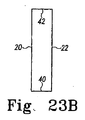
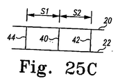
図21A〜図25Cは、本発明のインプラントのいくつかの実施形態の様々な構成を単純化した図によって表示する。図21Aは、軸方向のX線画像と一致する平面図である。図21Bは、横方向のX線画像と一致する側面図である。 FIGS. 21A-25C display various configurations of some embodiments of the implants of the present invention in simplified diagrams. FIG. 21A is a plan view coinciding with an axial X-ray image. FIG. 21B is a side view that coincides with the X-ray image in the horizontal direction.
図21Cは、後方から前方へのX線画像と一致する後面図である。 FIG. 21C is a rear view corresponding to the X-ray image from the rear to the front.
図21A〜図25Cに示すインプラントはそれぞれ、必要に応じて、上位枠部20、下位枠部22、後方支持体40、46、前方支持体44、42、および側方支持体25、26によって示される。支持体はそれぞれ、本明細書では円筒形の構成要素として示される。しかし、それぞれ、これらに限定されないが矩形、正方形、円形、楕円形、多角形など、任意の所望の構成でもよく、その長さに沿って断面が変わる構成でもよい。上記に記載したような、中央支柱410、第1のセグメント610、第2のセグメント611および管状部材612などの、X線撮影されにくいかX線透過性の部材は、図21A〜図25Cに示されないが、こうした部材の寸法または構成は、示されたインプラントそれぞれのために考えられる。脊椎前弯および後弯の矯正のための角形成は図21A〜図25Cに図示されず、こうした角形成は実施形態それぞれについて考えられる。
The implants shown in FIGS. 21A-25C are each indicated by
図21A〜図23Cおよび図25A〜図25Cは、前面、後面、および側面の少なくとも1つからX線写真で見るときの2つ以上の支持体の間の相対的な位置合わせと垂直軸の周りのインプラントの回転位置との間の関係をさらに示す。こうした向きのための垂直軸は、図示の後面図で見るときに垂直であると考えられる。 FIGS. 21A-23C and FIGS. 25A-25C illustrate relative alignment between two or more supports and about a vertical axis when viewed x-ray from at least one of the front, back, and sides. The relationship between the rotational position of the implants is further shown. The vertical axis for such orientation is considered vertical when viewed in the rear view shown.
図21A〜図21Cは、インプラントの後半分にある支持体40、46を示し、それらの支持体40、46は、インプラントをインプラントの後側からX線写真で見るときに、インプラントの前半分にある支持体42、44のX線写真による可視化を遮るように構成される。
21A-21C show the supports 40, 46 in the rear half of the implant, which supports 40, 46 in the front half of the implant when viewed from the back side of the implant in a radiograph. The
図21A〜図21Cはまた、インプラントの後半分にある支持体40を示し、その支持体40は、インプラントをインプラントの側面からX線写真で見るときに、インプラントの反対側の支持体46のX線写真による可視化を遮るように構成され、インプラントの前半分にある支持体42は、インプラントをインプラントの側面からX線写真で見るときに、インプラントの反対側の支持体44のX線写真による可視化を遮るように構成される。
FIGS. 21A-21C also show a
図22A〜図22Cは、インプラントの後半分にある支持体25を示し、その支持体25は、インプラントをインプラントの側面からX線写真で見るときに、インプラントの反対側の支持体26のX線写真による可視化を遮るように構成される。本明細書で使用されるように、後半分が前半分と後半分の間の中心線を含む。図22Cに示すように、インプラントを後側からX線写真で見るときに、支持体25と26の間の側方空間は、インプラントの回転位置を示す。したがって、後側から見るときに、支持体25、26を上位枠部20の端部と位置合わせすることは、インプラントの回転位置を示す。
22A-22C show a
図23A〜図23Cは、インプラントの後半分にある支持体40を示し、その支持体40は、インプラントをインプラントの後側からX線写真で見るときに、インプラントの前半分にある支持体42のX線写真による可視化を遮るように構成される。
FIGS. 23A-23C show a
インプラントを側面からX線写真で見るときに、インプラントの後半分にある支持体40とインプラントの前半分にある支持体42との間の前方から後方までの空間は、インプラントの回転位置を示す。さらに、側面から見るときの、支持体40、42と上位枠部20の端部との位置合わせは、インプラントの回転位置を示す。
When the implant is viewed from the side in a radiograph, the space from the front to the back between the
図24A〜図24Cは、1つまたは複数のX線写真で検出可能ではない材料またはX線透過性部材によって互いに連結された上位枠部20と下位枠部22を有するインプラントを示す。
FIGS. 24A-24C illustrate an implant having an
図25A〜図25Cは、インプラントを後側からX線写真で見るときに、インプラントの後半分にある支持体40とインプラントの前半分にある支持体42、44の間の側方空間S1、S2が実質上等距離であるインプラントを示す。図25A〜図25Cはまた、インプラントの前半分にある支持体42も示し、その支持体42は、インプラントをインプラントの側面からX線写真で見るときに、インプラントの反対側の支持体44のX線写真による可視化を遮るように構成される。
FIGS. 25A-25C show the lateral spaces S1, S2 between the
インプラントは、主として脊椎の固定の際に使用するように意図されるが、インプラントは、その中に、海綿骨、骨由来の生成物、化学療法薬、抗菌薬、またはその他のものなどであるがそれらに限定されない、固定促進物質および/または材料を受けるように改変または適合することができることが理解されよう。いくつかの実施形態では、インプラントは、チタンおよびその合金、ASTM規格の材料、コバルトクロム、タンタル、セラミック、ポリエーテルエーテルケトン(PEEK)、様々なプラスチック、プラスチック複合材、炭素繊維複合材、珊瑚などであるがこれらに限定されない材料からなり、少なくとも部分的に生体再吸収性(bioresorbable)のある人工の材料を含むことができる。インプラントに採り入れられた構造上の材料のX線像は、インプラントの配置、インプラントと骨の境界面ならびに/または骨の内方成長およびその中を通る成長の最適な可視化を実現することができるように、様々な性質であることが意図される。 The implant is primarily intended for use in spinal fixation, although the implant may include cancellous bone, bone-derived products, chemotherapeutic drugs, antibacterial drugs, or the like. It will be appreciated that modifications or adaptations can be received to receive, but are not limited to, fixation promoting substances and / or materials. In some embodiments, the implant is made of titanium and its alloys, ASTM standard materials, cobalt chrome, tantalum, ceramic, polyetheretherketone (PEEK), various plastics, plastic composites, carbon fiber composites, heels, etc. But not limited thereto, and may include artificial materials that are at least partially bioresorbable. X-ray images of the structural material incorporated in the implant can provide optimal visualization of implant placement, implant-bone interface and / or bone ingrowth and growth therethrough In addition, it is intended to have various properties.
説明によりインプラントの上面の下面に対する、平行かどうかなど様々な関係を明らかにするが、互いに対する表面間の意図的な角形成が可能であることに留意されたい。その次に、脊椎に植込まれるときに、このようなインプラントにより、互いに対する角度の関係における隣接する椎体の位置が、例えば脊椎前湾症など、脊椎の自然の湾曲を復元することが可能になる。インゲン豆形(腎臓形)、円形、くさび形、円筒形、台形、矩形、横長、および楕円を含むそれらに限定されないインプラントの形状の有意義な変形形態が、可能であることにも留意されたい。 It should be noted that the description reveals various relationships, such as parallel or not, to the lower surface of the upper surface of the implant, but intentional angulation between the surfaces relative to each other is possible. Then, when implanted in the spine, such implants allow the positions of adjacent vertebral bodies in an angular relationship to each other to restore the natural curvature of the spine, for example, prespondylosis. become. It should also be noted that significant variations in the shape of implants are possible including, but not limited to, kidney bean (kidney), circular, wedge, cylindrical, trapezoidal, rectangular, oblong, and elliptical.
外側表面は、周りの組織または骨への挿入または固定を改善するためのねじ山または特定の凹凸を含むことができる。本発明の実施形態のどれでも、インプラントは、ヒトの脊椎に植込むのに適した人工の材料または自然に発生する材料および/あるいは物質を含むか、それから作られるか、扱われるか、被覆されるか、充填されるか、それらと一緒に使用されるか、あるいはそれらを含むための中空の空間または開口部を有することができる。これらの材料および/または物質は、骨形成、骨の成長を促進する材料、骨、骨由来の物質または生成物、鉱物質を除去した骨基質、無機質化蛋白質、骨化蛋白質、骨形成蛋白質、ヒドロキシアパタイト、骨生成のための遺伝子コード、ならびに皮質骨、抗生物質、癌治療物質、感染症治療物質または他の病気を治療する物質を含むがそれらに限定されない骨の任意の供給源を含むことができる。インプラントは、少なくとも部分的に、生体吸収性および/または人体で再吸収可能な材料を含むことができる。本発明のインプラントを、多孔質材料から形成することができ、または隣接する椎体間の骨の成長に本質的に関係する材料から形成することができる。インプラントの少なくとも一部分は、インプラントと隣接する椎体の間の骨の内方成長を促進するように処理することができる。 The outer surface can include threads or certain irregularities to improve insertion or fixation into surrounding tissue or bone. In any of the embodiments of the present invention, the implant includes, is made from, treated, or coated with artificial materials or naturally occurring materials and / or substances suitable for implantation in the human spine. Can be filled, used with them, or have a hollow space or opening to contain them. These materials and / or substances include bone formation, bone growth-promoting materials, bone, bone-derived substances or products, bone matrix from which mineral substances have been removed, mineralized protein, ossified protein, bone morphogenetic protein, Includes any source of bone, including but not limited to hydroxyapatite, the genetic code for bone formation, and cortical bone, antibiotics, cancer therapeutics, infectious diseases or other diseases Can do. The implant can include, at least in part, a material that is bioabsorbable and / or resorbable by the human body. The implants of the present invention can be formed from a porous material or can be formed from a material that is essentially involved in bone growth between adjacent vertebral bodies. At least a portion of the implant can be treated to promote bone ingrowth between the implant and the adjacent vertebral body.
本発明のインプラントは、椎体間の脊椎インプラント、構造上の骨移植片、網目、ケージ、スペーサ、ステープル、骨スクリュ、プレート、ロッド、合成材料のテザーまたはワイヤ、あるいは他の脊椎固定インストルメンテーションなどであるが、それらに限定されない、材料にかかわらず脊椎の任意の部分に挿入することができる任意の装置などの、脊椎固定装置と組み合わせて使用することができる。本発明を特定の実施形態を参照して説明してきたが、本発明の精神および範囲から逸脱することなく本発明自体に様々な改変を行うことができることが当業者には理解されよう。本発明の精神に包含されるすべての変更および改変が、本明細書によって予期され、特許請求の範囲に含まれる。 The implants of the present invention may be intervertebral spinal implants, structural bone grafts, meshes, cages, spacers, staples, bone screws, plates, rods, synthetic tethers or wires, or other spinal fixation instrumentation. And can be used in combination with spinal fixation devices, such as, but not limited to, any device that can be inserted into any part of the spine, regardless of material. Although the invention has been described with reference to particular embodiments, those skilled in the art will recognize that various modifications can be made to the invention itself without departing from the spirit and scope of the invention. All changes and modifications that fall within the spirit of the invention are contemplated by the specification and are covered by the claims.
本発明に属する方法は、前方手術アプローチから椎間インプラントを植込むステップを含む。インプラントの外周の周りの第1の枠部であって、検出可能なX線撮影によるサインを有する第1の枠部と、第1の枠部に連結された部材であって、第1の枠部よりX線撮影によるサインが少ない部材とを備えるインプラントが提供される。その部材は、第1の枠部に椎骨の間隔の高さを追加する。適合性のあるX線写真の特徴を有する他のインプラントも、この方法のいくつかの実施形態の下で使用するように考えられる。 The method belonging to the present invention includes the step of implanting an intervertebral implant from an anterior surgical approach. A first frame around the outer periphery of the implant, the first frame having a detectable X-ray sign and a member connected to the first frame, the first frame There is provided an implant including a member having less sign by X-ray imaging than the portion. The member adds vertebral spacing height to the first frame. Other implants with compatible radiographic features are also contemplated for use under some embodiments of the method.
その方法はさらに、上位椎体と下位椎体の間のインプラントの配置をX線写真で観察するステップを含む。この観察は、1つまたは複数の前方から後方へのX線像および側方のX線像に沿ってX線画像を取り込むことによって実現することができる。いくつかの実施形態においてこうしたX線写真で見ることは、任意の側方から見ることを含み、後方、前方、および側方に直線的に向くことに限定されないが、これらの方向から斜めにそれることも含む。効果的にX線写真で見ることが、中心から側方および前方から後面を見る経路を提供する本発明のいくつかの実施形態によって可能になる。しかし、構造的に支持しかつ医師にインプラントの方向を知らせる、X線不透過性の材料の選択的な配置は、こうした見る経路と組み合わせて本発明のいくつかの実施形態に存在する。 The method further includes the step of observing the placement of the implant between the upper and lower vertebral bodies with a radiograph. This observation can be realized by capturing X-ray images along one or more front-to-back X-ray images and lateral X-ray images. In some embodiments, viewing in such a radiograph includes viewing from any side, including but not limited to facing straight back, front, and side, but obliquely from these directions. Including. Effective radiographic viewing is enabled by some embodiments of the present invention that provide a path for viewing from the center to the side and from the front to the back. However, selective placement of radiopaque material that provides structural support and informs the physician of the orientation of the implant is present in some embodiments of the present invention in combination with such viewing paths.
インプラントの配置をX線写真で観察するステップは、インプラントの上位部分と下位部分の間を延びる2つ以上の支持体の相対的な位置合わせを観察するステップを含む。第1の枠部に連結された2つ以上の支持体の相対的な位置合わせを観察することによって、インプラントの方向を判定することができる。 Observing the placement of the implant with a radiograph includes observing the relative alignment of two or more supports extending between the upper and lower portions of the implant. By observing the relative alignment of two or more supports coupled to the first frame, the orientation of the implant can be determined.
その方法は、1つまたは複数の前方から後方へのX線像および側方X線像に沿ってX線画像を取り込むことによって、上位椎体と下位椎体の間の骨の成長をX線写真で観察するステップも含む。いくつかの実施形態におけるこうしたX線写真による見ることは、任意の側方から見ることを含み、後方、前方、および側方に直線的に向くことに限定されないが、これらの方向から斜めにそれることも含む。骨の成長の観察は、骨成長の体積およびX線透過性材料のみを含むインプラントを介して提供される見る経路を提供することによって強化される。 The method captures bone growth between the upper and lower vertebral bodies by capturing X-ray images along one or more anterior-to-posterior and lateral X-ray images. It also includes the step of observing with photographs. Such radiographic viewing in some embodiments includes viewing from any side, including but not limited to pointing straight back, front, and side, but obliquely from these directions. Including. The observation of bone growth is enhanced by providing a viewing path provided through the bone growth volume and an implant containing only radiolucent material.
椎間インプラントを組み立てる方法が、インプラントの外周の周りの第1の枠部であって、検出可能なX線撮影によるサインを有する第1の枠部と、第1の枠部に連結された支持体であって、検出可能なX線撮影によるサインを有する支持体と、支持体に連結された第2の枠部であって、検出可能なX線撮影によるサインを有する第2の枠部とを有するインプラントを提供するステップを含む。 A method for assembling an intervertebral implant is a first frame around an outer periphery of the implant, the first frame having a detectable radiographic sign, and a support coupled to the first frame A body having a detectable X-ray imaging sign and a second frame connected to the support, the second frame having a detectable X-ray imaging sign Providing an implant having:
この方法のいくつかの実施形態は、第1の枠部と第2の枠部の間に部材を適用するステップを含む。実施形態の部材は、第1の枠部よりX線撮影によるサインが少ない。一例として、その部材は、PEEKなどのX線透過性材料でよい。本明細書に示されるように、その部材は、中央支柱410、第1のセグメント610、第2のセグメント611、または管状部材612のうち1つまたは複数を含むことができる。
Some embodiments of the method include applying a member between the first frame and the second frame. The member of the embodiment has fewer signs by X-ray imaging than the first frame portion. As an example, the member may be an X-ray transmissive material such as PEEK. As shown herein, the member can include one or more of a
部材の適用は様々なやり方で実現することができる。その遠位端は、第1の枠部、第2の枠部、および支持体のうち1つの少なくとも一部分の周りに形成することができる。これを実現するためには、部材の材料は、第1の枠部、第2の枠部、および支持体のうち1つの少なくとも一部分の周りに注入成形、射出成形、または直接成型することができる。本体を、成型または注入成形の一部として含むこともでき、第1の枠部、第2の枠部、および支持体のうち1つの一部分に適用するために成型または注入成形内に封入することもできる。 The application of the member can be realized in various ways. The distal end can be formed around at least a portion of one of the first frame, the second frame, and the support. To achieve this, the material of the member can be injection molded, injection molded, or directly molded around at least a portion of one of the first frame, the second frame, and the support. . The body can also be included as part of molding or injection molding and encapsulated within molding or injection molding for application to a portion of one of the first frame, second frame, and support. You can also.
その部材を適用するステップは、材料を、第1の枠部、第2の枠部、および支持体の少なくとも1つの少なくとも一部分と相互連結するステップも含む。相互連結するステップは、第1の枠部、第2の枠部、および支持体のうち少なくとも1つの一部分を封入することなしに、注入成形、射出成形または成型材料を含むこともできる。材料の相互連結は、切削加工、注入成形、形成、射出成形、または成型によって第1の枠部、第2の枠部、および支持体から完全に別個に部材を形成するステップも含むことができる。部材が形成された後で、接着、嵌合、または相互接続の任意の方法によって本体に適用することができる。いくつかの実施形態では、第1の枠部、第2の枠部、および支持体に、それらの間に、またはそれらの中に部材の材料をスナップ嵌めすることによって、相互連結を実現することができる。 Applying the member also includes interconnecting the material with at least a portion of at least one of the first frame, the second frame, and the support. The interconnecting step can also include injection molding, injection molding or molding material without encapsulating a portion of at least one of the first frame, the second frame, and the support. The material interconnection can also include forming the member completely separate from the first frame, the second frame, and the support by cutting, injection molding, forming, injection molding, or molding. . After the member is formed, it can be applied to the body by any method of gluing, mating, or interconnecting. In some embodiments, interconnecting is achieved by snap-fitting member material between, or within, the first frame, the second frame, and the support. Can do.
本発明の実施形態を、この開示の詳細に図示し説明してきたが、その開示は、例示的なものであると考えられ、特徴を限定するとものではないと考えるべきである。本発明の精神に包含されるすべての変更形態および改変形態は、開示の範囲内に包含されると考えるべきである。 While embodiments of the present invention have been illustrated and described in detail in this disclosure, the disclosure is to be regarded as illustrative and not limiting in nature. All changes and modifications that come within the spirit of the invention should be considered within the scope of the disclosure.
Claims (24)
前記インプラントの外周の周りの第1の枠部であって、検出可能なX線撮影によるサインを有する、第1の枠部と、
前記第1の枠部に連結された部材であって、前記第1の枠部より低いX線撮影によるサインを有する、部材とを備え、
前記部材が、前記第1の枠部に椎骨の間隔の高さを加える、椎間インプラント。 In an intervertebral implant having an overall round profile to promote fusion between the lower and upper vertebral bodies,
A first frame around the outer periphery of the implant, the first frame having a detectable radiographic sign;
A member connected to the first frame part, the member having a sign by X-ray imaging lower than the first frame part,
An intervertebral implant, wherein the member adds a vertebral spacing height to the first frame.
Applications Claiming Priority (2)
| Application Number | Priority Date | Filing Date | Title |
|---|---|---|---|
| US72055505P | 2005-09-26 | 2005-09-26 | |
| PCT/US2006/037550 WO2007038546A1 (en) | 2005-09-26 | 2006-09-26 | Anterior hybrid implant |
Publications (1)
| Publication Number | Publication Date |
|---|---|
| JP2009509591A true JP2009509591A (en) | 2009-03-12 |
Family
ID=38420660
Family Applications (1)
| Application Number | Title | Priority Date | Filing Date |
|---|---|---|---|
| JP2008532500A Pending JP2009509591A (en) | 2005-09-26 | 2006-09-26 | Anterior composite implant |
Country Status (5)
| Country | Link |
|---|---|
| US (1) | US8764832B2 (en) |
| EP (1) | EP1942837B1 (en) |
| JP (1) | JP2009509591A (en) |
| AT (1) | ATE539710T1 (en) |
| WO (1) | WO2007038546A1 (en) |
Families Citing this family (58)
| Publication number | Priority date | Publication date | Assignee | Title |
|---|---|---|---|---|
| EP1587437B1 (en) | 2003-01-31 | 2013-02-27 | Spinalmotion, Inc. | Spinal midline indicator |
| WO2004066884A1 (en) | 2003-01-31 | 2004-08-12 | Spinalmotion, Inc. | Intervertebral prosthesis placement instrument |
| US7575599B2 (en) | 2004-07-30 | 2009-08-18 | Spinalmotion, Inc. | Intervertebral prosthetic disc with metallic core |
| ATE480203T1 (en) * | 2003-05-27 | 2010-09-15 | Spinalmotion Inc | INTERVERTEBRAL DISC PROSTHESIS FOR INTERVERTEBRAL INSERTION |
| US10052211B2 (en) | 2003-05-27 | 2018-08-21 | Simplify Medical Pty Ltd. | Prosthetic disc for intervertebral insertion |
| US7585326B2 (en) | 2004-08-06 | 2009-09-08 | Spinalmotion, Inc. | Methods and apparatus for intervertebral disc prosthesis insertion |
| US8083797B2 (en) | 2005-02-04 | 2011-12-27 | Spinalmotion, Inc. | Intervertebral prosthetic disc with shock absorption |
| US8814939B2 (en) | 2005-05-06 | 2014-08-26 | Titan Spine, Llc | Implants having three distinct surfaces |
| US8480749B2 (en) | 2005-05-06 | 2013-07-09 | Titan Spine, Llc | Friction fit and vertebral endplate-preserving spinal implant |
| US8545568B2 (en) | 2005-05-06 | 2013-10-01 | Titan Spine, Llc | Method of using instruments and interbody spinal implants to enhance distraction |
| US8562684B2 (en) | 2005-05-06 | 2013-10-22 | Titan Spine, Llc | Endplate-preserving spinal implant with an integration plate having a roughened surface topography |
| US8591590B2 (en) | 2005-05-06 | 2013-11-26 | Titan Spine, Llc | Spinal implant having a transverse aperture |
| US8758443B2 (en) | 2005-05-06 | 2014-06-24 | Titan Spine, Llc | Implants with integration surfaces having regular repeating surface patterns |
| US8403991B2 (en) | 2005-05-06 | 2013-03-26 | Titan Spine Llc | Implant with critical ratio of load bearing surface area to central opening area |
| US8262737B2 (en) * | 2005-05-06 | 2012-09-11 | Titan Spine, Llc | Composite interbody spinal implant having openings of predetermined size and shape |
| US8435302B2 (en) | 2005-05-06 | 2013-05-07 | Titan Spine, Llc | Instruments and interbody spinal implants enhancing disc space distraction |
| US8551176B2 (en) | 2005-05-06 | 2013-10-08 | Titan Spine, Llc | Spinal implant having a passage for enhancing contact between bone graft material and cortical endplate bone |
| US8585766B2 (en) | 2005-05-06 | 2013-11-19 | Titan Spine, Llc | Endplate-preserving spinal implant with an integration plate having durable connectors |
| US8562685B2 (en) | 2005-05-06 | 2013-10-22 | Titan Spine, Llc | Spinal implant and integration plate for optimizing vertebral endplate contact load-bearing edges |
| US9125756B2 (en) | 2005-05-06 | 2015-09-08 | Titan Spine, Llc | Processes for producing regular repeating patterns on surfaces of interbody devices |
| US8585765B2 (en) | 2005-05-06 | 2013-11-19 | Titan Spine, Llc | Endplate-preserving spinal implant having a raised expulsion-resistant edge |
| US8617248B2 (en) | 2005-05-06 | 2013-12-31 | Titan Spine, Llc | Spinal implant having variable ratios of the integration surface area to the axial passage area |
| US9168147B2 (en) | 2005-05-06 | 2015-10-27 | Titan Spine, Llc | Self-deploying locking screw retention device |
| US8585767B2 (en) | 2005-05-06 | 2013-11-19 | Titan Spine, Llc | Endplate-preserving spinal implant with an integration plate having durable connectors |
| US20120312779A1 (en) | 2005-05-06 | 2012-12-13 | Titian Spine, LLC | Methods for manufacturing implants having integration surfaces |
| US8758442B2 (en) | 2005-05-06 | 2014-06-24 | Titan Spine, Llc | Composite implants having integration surfaces composed of a regular repeating pattern |
| US8992622B2 (en) | 2005-05-06 | 2015-03-31 | Titan Spine, Llc | Interbody spinal implant having a roughened surface topography |
| US11096796B2 (en) | 2005-05-06 | 2021-08-24 | Titan Spine, Llc | Interbody spinal implant having a roughened surface topography on one or more internal surfaces |
| KR20090007418A (en) | 2006-04-12 | 2009-01-16 | 스피날모우션, 인코포레이티드 | Posterior spinal device and method |
| US20090043391A1 (en) | 2007-08-09 | 2009-02-12 | Spinalmotion, Inc. | Customized Intervertebral Prosthetic Disc with Shock Absorption |
| WO2009055478A1 (en) | 2007-10-22 | 2009-04-30 | Spinalmotion, Inc. | Vertebral body replacement and method for spanning a space formed upon removal of a vertebral body |
| US9034038B2 (en) | 2008-04-11 | 2015-05-19 | Spinalmotion, Inc. | Motion limiting insert for an artificial intervertebral disc |
| KR20110009216A (en) | 2008-05-05 | 2011-01-27 | 스피날모우션, 인코포레이티드 | Polyaryletherketone artificial intervertebral disc |
| US9220603B2 (en) | 2008-07-02 | 2015-12-29 | Simplify Medical, Inc. | Limited motion prosthetic intervertebral disc |
| EP2299944A4 (en) | 2008-07-17 | 2013-07-31 | Spinalmotion Inc | Artificial intervertebral disc placement system |
| EP2299941A1 (en) | 2008-07-18 | 2011-03-30 | Spinalmotion Inc. | Posterior prosthetic intervertebral disc |
| WO2010080511A1 (en) * | 2008-12-18 | 2010-07-15 | 4-Web Spine, Inc. | Truss implant |
| US20100158209A1 (en) * | 2008-12-22 | 2010-06-24 | General Instrument Corporation | Access to Network Based on Automatic Speech-Recognition |
| US9414923B2 (en) | 2010-04-15 | 2016-08-16 | Warsaw Orthopedic, Inc. | Implant and method for producing an implant |
| US8992619B2 (en) | 2011-11-01 | 2015-03-31 | Titan Spine, Llc | Microstructured implant surfaces |
| CA2880825C (en) | 2012-03-20 | 2021-03-16 | Titan Spine, Llc | Friction-fit spinal endplate and endplate-preserving method |
| US9585764B2 (en) * | 2012-07-26 | 2017-03-07 | Warsaw Orthopedic, Inc. | Bone implant device |
| US12115071B2 (en) | 2012-09-25 | 2024-10-15 | 4Web, Llc | Programmable intramedullary implants and methods of using programmable intramedullary implants to repair bone structures |
| AU2013323602B2 (en) | 2012-09-25 | 2018-02-22 | 4Web, Inc. | Programmable implants and methods of using programmable implants to repair bone structures |
| EP2716261A1 (en) | 2012-10-02 | 2014-04-09 | Titan Spine, LLC | Implants with self-deploying anchors |
| US9498349B2 (en) | 2012-10-09 | 2016-11-22 | Titan Spine, Llc | Expandable spinal implant with expansion wedge and anchor |
| WO2014145529A2 (en) | 2013-03-15 | 2014-09-18 | 4-Web, Inc. | Traumatic bone fracture repair systems and methods |
| US9615935B2 (en) | 2014-01-30 | 2017-04-11 | Titan Spine, Llc | Thermally activated shape memory spring assemblies for implant expansion |
| US10687956B2 (en) | 2014-06-17 | 2020-06-23 | Titan Spine, Inc. | Corpectomy implants with roughened bioactive lateral surfaces |
| TWI726940B (en) | 2015-11-20 | 2021-05-11 | 美商泰坦脊柱股份有限公司 | Processes for additively manufacturing orthopedic implants |
| JP2019523092A (en) | 2016-08-03 | 2019-08-22 | タイタン スパイン インコーポレイテッドTitan Spine,Inc. | Titanium implant surface without alpha case and enhanced bone guidance |
| US10918497B1 (en) | 2017-10-24 | 2021-02-16 | Omnia Medical, LLC | Multi-material multi-component spinal implant |
| US11766339B1 (en) | 2017-10-24 | 2023-09-26 | Omnia Medical, LLC | Multi-material multi-component spinal implant |
| US10973658B2 (en) | 2017-11-27 | 2021-04-13 | Titan Spine, Inc. | Rotating implant and associated instrumentation |
| US11135070B2 (en) | 2018-02-14 | 2021-10-05 | Titan Spine, Inc. | Modular adjustable corpectomy cage |
| US10682238B2 (en) * | 2018-05-08 | 2020-06-16 | Globus Medical, Inc. | Intervertebral spinal implant |
| AU2020385014A1 (en) | 2019-11-15 | 2022-06-30 | 4Web, Inc. | Piezoelectric coated implants and methods of using piezoelectric coated implants to repair bone structures |
| US11826265B2 (en) * | 2021-06-28 | 2023-11-28 | Spine Wave, Inc. | Bellows shaped spinal implant having gyroid lattice structures |
Citations (3)
| Publication number | Priority date | Publication date | Assignee | Title |
|---|---|---|---|---|
| JP2002526127A (en) * | 1998-05-06 | 2002-08-20 | コーテック・インコーポレーテッド | Spinal fixation device and method using implantable device |
| WO2005041816A2 (en) * | 2003-10-20 | 2005-05-12 | Blackstone Medical, Inc. | Vertebral body replacement apparatus and method |
| JP2005520629A (en) * | 2002-03-21 | 2005-07-14 | エスディージーアイ・ホールディングス・インコーポレーテッド | Vertebral body and disc space replacement device |
Family Cites Families (39)
| Publication number | Priority date | Publication date | Assignee | Title |
|---|---|---|---|---|
| CA1318469C (en) * | 1989-02-15 | 1993-06-01 | Acromed Corporation | Artificial disc |
| US5192327A (en) * | 1991-03-22 | 1993-03-09 | Brantigan John W | Surgical prosthetic implant for vertebrae |
| US5397364A (en) * | 1993-10-12 | 1995-03-14 | Danek Medical, Inc. | Anterior interbody fusion device |
| US6039762A (en) * | 1995-06-07 | 2000-03-21 | Sdgi Holdings, Inc. | Reinforced bone graft substitutes |
| US6682561B2 (en) * | 1998-06-18 | 2004-01-27 | Pioneer Laboratories, Inc. | Spinal fixation system |
| US6090143A (en) | 1998-09-21 | 2000-07-18 | Meriwether; Michael W. | Box cage for intervertebral body fusion |
| US6159211A (en) * | 1998-10-22 | 2000-12-12 | Depuy Acromed, Inc. | Stackable cage system for corpectomy/vertebrectomy |
| US6126688A (en) * | 1998-12-21 | 2000-10-03 | Surgical Dynamics Inc. | Apparatus for fusion of adjacent bone structures |
| US6447543B1 (en) * | 1999-09-28 | 2002-09-10 | Sulzer Orthopedics Ltd. | Basket-like container for implanting bone tissue |
| US6461359B1 (en) * | 1999-11-10 | 2002-10-08 | Clifford Tribus | Spine stabilization device |
| US6296665B1 (en) * | 2000-03-20 | 2001-10-02 | Electro-Biology, Inc. | Method and apparatus for spinal fixation |
| FR2811543B1 (en) * | 2000-07-12 | 2003-07-04 | Spine Next Sa | INTERSOMATIC IMPLANT |
| US6468311B2 (en) * | 2001-01-22 | 2002-10-22 | Sdgi Holdings, Inc. | Modular interbody fusion implant |
| ES2262621T3 (en) * | 2001-01-30 | 2006-12-01 | Synthes Ag Chur | IMPLANT OF OSTEOSYNTHESIS, IN SPECIAL INTERVERTEBRAL IMPLANT. |
| DE60138521D1 (en) * | 2001-02-27 | 2009-06-10 | Co Ligne Ag | Medical implant |
| US20040186570A1 (en) * | 2001-04-04 | 2004-09-23 | Rapp Lawrence G | Interbody spinal fusion device |
| ATE419810T1 (en) * | 2001-05-01 | 2009-01-15 | Amedica Corp | RADIO-LUCENT BONE TRANSPLANT |
| US20050177238A1 (en) * | 2001-05-01 | 2005-08-11 | Khandkar Ashok C. | Radiolucent bone graft |
| DE50114038D1 (en) * | 2001-08-24 | 2008-07-31 | Zimmer Gmbh | Artificial disc |
| ATE398430T1 (en) * | 2001-08-24 | 2008-07-15 | Zimmer Gmbh | ARTIFICIAL DISC |
| US20030139812A1 (en) * | 2001-11-09 | 2003-07-24 | Javier Garcia | Spinal implant |
| US6979353B2 (en) * | 2001-12-03 | 2005-12-27 | Howmedica Osteonics Corp. | Apparatus for fusing adjacent bone structures |
| US7238203B2 (en) * | 2001-12-12 | 2007-07-03 | Vita Special Purpose Corporation | Bioactive spinal implants and method of manufacture thereof |
| DK175391B1 (en) * | 2002-02-13 | 2004-09-20 | Danfoss As | Column implant and method of manufacture thereof |
| US6991653B2 (en) * | 2002-03-21 | 2006-01-31 | Sdgi Holdings, Inc. | Vertebral body and disc space replacement devices |
| US6726720B2 (en) * | 2002-03-27 | 2004-04-27 | Depuy Spine, Inc. | Modular disc prosthesis |
| US7674297B2 (en) * | 2002-06-14 | 2010-03-09 | U.S. Spinal Technologies, Llc | Anatomic vertebral cage |
| BR0313499A (en) * | 2002-08-15 | 2005-07-05 | David Gerber | Intervertebral disc |
| US6712852B1 (en) * | 2002-09-30 | 2004-03-30 | Depuy Spine, Inc. | Laminoplasty cage |
| US6899735B2 (en) * | 2002-10-02 | 2005-05-31 | Sdgi Holdings, Inc. | Modular intervertebral prosthesis system |
| US7232463B2 (en) * | 2002-10-23 | 2007-06-19 | U.S. Spinal Technologies, Llc | Intervertebral cage designs |
| US7192447B2 (en) * | 2002-12-19 | 2007-03-20 | Synthes (Usa) | Intervertebral implant |
| EP1596772B1 (en) | 2003-02-12 | 2011-04-13 | Warsaw Orthopedic, Inc. | Device for fusing two bone segments |
| US7806932B2 (en) * | 2003-08-01 | 2010-10-05 | Zimmer Spine, Inc. | Spinal implant |
| FR2861582B1 (en) * | 2003-10-29 | 2006-02-10 | Eurosurgical | INTERSOMATIC CAGE FOR LUMBAR FUSION FIRST TRANSFORAMINAL AND CAGE HOLDER DEVICE |
| US7137997B2 (en) * | 2003-12-29 | 2006-11-21 | Globus Medical, Inc. | Spinal fusion implant |
| US7875080B2 (en) * | 2004-11-10 | 2011-01-25 | Warsaw Orthopedic, Inc. | Intervertebral spacer |
| US7662186B2 (en) * | 2005-05-06 | 2010-02-16 | Titan Spine, Llc | Anterior interbody spinal implant |
| US8262737B2 (en) * | 2005-05-06 | 2012-09-11 | Titan Spine, Llc | Composite interbody spinal implant having openings of predetermined size and shape |
-
2006
- 2006-09-26 JP JP2008532500A patent/JP2009509591A/en active Pending
- 2006-09-26 EP EP06815502A patent/EP1942837B1/en active Active
- 2006-09-26 AT AT06815502T patent/ATE539710T1/en active
- 2006-09-26 US US11/527,123 patent/US8764832B2/en active Active
- 2006-09-26 WO PCT/US2006/037550 patent/WO2007038546A1/en active Application Filing
Patent Citations (3)
| Publication number | Priority date | Publication date | Assignee | Title |
|---|---|---|---|---|
| JP2002526127A (en) * | 1998-05-06 | 2002-08-20 | コーテック・インコーポレーテッド | Spinal fixation device and method using implantable device |
| JP2005520629A (en) * | 2002-03-21 | 2005-07-14 | エスディージーアイ・ホールディングス・インコーポレーテッド | Vertebral body and disc space replacement device |
| WO2005041816A2 (en) * | 2003-10-20 | 2005-05-12 | Blackstone Medical, Inc. | Vertebral body replacement apparatus and method |
Also Published As
| Publication number | Publication date |
|---|---|
| US8764832B2 (en) | 2014-07-01 |
| WO2007038546A1 (en) | 2007-04-05 |
| EP1942837A1 (en) | 2008-07-16 |
| ATE539710T1 (en) | 2012-01-15 |
| US20070233248A1 (en) | 2007-10-04 |
| EP1942837B1 (en) | 2012-01-04 |
Similar Documents
| Publication | Publication Date | Title |
|---|---|---|
| JP2009509591A (en) | Anterior composite implant | |
| JP5291464B2 (en) | Composite intervertebral spinal fusion implant | |
| US7998212B2 (en) | Transforaminal hybrid implant | |
| US7871441B2 (en) | Cervical fixation device | |
| US8591589B2 (en) | Interbody fusion device | |
| US6723097B2 (en) | Surgical trial implant | |
| AU772498B2 (en) | Spinal fusion implant | |
| US7815682B1 (en) | Spinal fusion implant and related methods | |
| CN104023674B (en) | Inflatable intervertebral implant | |
| EP1290985A2 (en) | Intersomatic cage for posterior fusion surgery to the lumbar column and for surgery involving the insertion of a transforaminal implant | |
| JP6590788B2 (en) | Composite interbody device and method | |
| US20110054614A1 (en) | Implant retaining device | |
| JP2008541852A (en) | Osteoconductive spinal fixation system | |
| KR20090118909A (en) | Methods and apparatus for minimally invasive modular interbody fusion devices | |
| CN105392434A (en) | Spinal construct and method | |
| WO2002045592A9 (en) | Implant retaining device | |
| US20200054455A1 (en) | Interbody standalone device with integrated fixations |
Legal Events
| Date | Code | Title | Description |
|---|---|---|---|
| A621 | Written request for application examination |
Free format text: JAPANESE INTERMEDIATE CODE: A621 Effective date: 20090831 |
|
| A977 | Report on retrieval |
Free format text: JAPANESE INTERMEDIATE CODE: A971007 Effective date: 20110517 |
|
| A131 | Notification of reasons for refusal |
Free format text: JAPANESE INTERMEDIATE CODE: A131 Effective date: 20110520 |
|
| A601 | Written request for extension of time |
Free format text: JAPANESE INTERMEDIATE CODE: A601 Effective date: 20110819 |
|
| A602 | Written permission of extension of time |
Free format text: JAPANESE INTERMEDIATE CODE: A602 Effective date: 20110826 |
|
| RD04 | Notification of resignation of power of attorney |
Free format text: JAPANESE INTERMEDIATE CODE: A7424 Effective date: 20110914 |
|
| A02 | Decision of refusal |
Free format text: JAPANESE INTERMEDIATE CODE: A02 Effective date: 20120131 |