JP2007183735A - Electronic device - Google Patents
Electronic device Download PDFInfo
- Publication number
- JP2007183735A JP2007183735A JP2006000643A JP2006000643A JP2007183735A JP 2007183735 A JP2007183735 A JP 2007183735A JP 2006000643 A JP2006000643 A JP 2006000643A JP 2006000643 A JP2006000643 A JP 2006000643A JP 2007183735 A JP2007183735 A JP 2007183735A
- Authority
- JP
- Japan
- Prior art keywords
- board
- cable
- pulled out
- state
- electronic device
- Prior art date
- Legal status (The legal status is an assumption and is not a legal conclusion. Google has not performed a legal analysis and makes no representation as to the accuracy of the status listed.)
- Pending
Links
Images


Landscapes
- Cooling Or The Like Of Electrical Apparatus (AREA)
- Mounting Of Printed Circuit Boards And The Like (AREA)
Abstract
Description
本発明は電子装置に係り、特にラックに搭載される薄型サーバの実装構造に関するものである。 The present invention relates to an electronic device, and more particularly to a mounting structure of a thin server mounted on a rack.
この種の薄型サーバとして1Uサーバが知られている。1Uサーバは、厚さ約44.5mmの大きさで、1区画が19インチのラックに収まる形状である。縦横19インチ、高さ44.5mmを1区画とする慣例からこのサイズを1U(ユニット)と呼んでいる。この薄型サーバには、CPUやメモリの他、ハードディスク(HDD)、CD−ROM,FDD等が実装されており、顧客から要求される処理能力に応じて、薄型サーバの台数を増やしてラックに収納している。設置環境によっては1台のラックに30台以上の1Uサーバが搭載される場合もある。 A 1U server is known as this type of thin server. The 1U server has a thickness of about 44.5 mm and a shape in which one section fits in a 19-inch rack. This size is called 1U (unit) from the convention of 19 inches in length and width and 44.5 mm in height as one section. In addition to the CPU and memory, this thin server is equipped with a hard disk (HDD), CD-ROM, FDD, etc. The number of thin servers is increased and stored in a rack according to the processing capacity required by customers. is doing. Depending on the installation environment, 30 or more 1U servers may be mounted in one rack.
薄型サーバの実装構造に関して、例えば、特開2003−36669公報(特許文献1)には、サーバユニット内のハードディスク装置(HDD)の交換を容易にするために、サーバユニットのケースを前面に移動可能な引出し構造として、全てのHDDの交換を前面側から行なえるようにした電子機器及びラックの技術が開示されている。 Regarding the mounting structure of a thin server, for example, in Japanese Patent Laid-Open No. 2003-36669 (Patent Document 1), the case of the server unit can be moved to the front to facilitate the replacement of the hard disk device (HDD) in the server unit. As a simple drawer structure, an electronic device and a rack technology are disclosed in which all HDDs can be replaced from the front side.
近年、サーバは24時間稼動が求められている。このため、障害発生時やメンテナンス時には、できるだけサーバを稼働しながら作業を行なうか、或いはサーバの停止時間を極力短くしてそれらの作業を行なうのが好ましい。 In recent years, servers are required to operate for 24 hours. For this reason, when a failure occurs or during maintenance, it is preferable to perform the work while operating the server as much as possible, or to perform the work with the server down time as short as possible.
上記特許文献1の技術によれば、サーバユニットを引き伸ばす構造になっておらず、作業時はユニット全体を前面に移動して行なうことになる。このため、ケーブルの背面の接続部まで含めた部分も前面に引き出されるので、ユニットの背面に接続されているケーブルが抜ける恐れがある。また、ラックに搭載されるユニットの保守に際しては、ラックからユニットを下ろさなければ、サーバ内の保守作業等ができないことになる。
また、上記特許文献1には、ケーブルの処理やケーブルダクトについては言及されていない。
According to the technique disclosed in
Further,
本発明の目的は、サーバをラックから下ろさなくても、保守作業を容易に行なうことができる電子装置を提供することにある。
本発明は、電子部品を実装するボードを複数に分割して1つのボードを前面側に引き出し可能とした薄型サーバの新規な実装構造を提供することにある。
An object of the present invention is to provide an electronic apparatus that can easily perform maintenance work without taking a server down from a rack.
An object of the present invention is to provide a novel mounting structure for a thin server in which an electronic component mounting board is divided into a plurality of boards and one board can be pulled out to the front side.
本発明は、ラックに引き出し可能な状態で搭載される、電子部品を実装した薄型形状の電子装置であって、ある種の電子部品を実装した第1のボードと、第1のボードに対して装置の前面側に引き出し可能に構成された、ある種の電子部品を実装した第2のボードと、第1のボードと第2のボードにそれぞれの端部が接続されたケーブルと、を備え、第1のボードに対して第2のボードを前面側に引き出すとき、第1のボード側のケーブルの接続部を固定した状態で、第2のボードを引き出すように構成した電子装置である。 The present invention is a thin electronic device mounted with electronic components mounted in a state that can be pulled out to a rack, and includes a first board mounted with a certain kind of electronic component, and a first board. A second board on which a certain type of electronic component is mounted, which can be pulled out on the front side of the apparatus, and a cable connected to each end of the first board and the second board; The electronic device is configured such that when the second board is pulled out to the front side with respect to the first board, the second board is pulled out in a state where the connection portion of the cable on the first board side is fixed.
好ましい例では、本発明は、ラックに引き出し可能な状態で搭載される、電子部品を実装した薄型形状の電子装置であって、ある種の電子部品を実装した第1のボードと、第1のボードに対して装置の前面側に引き出し可能に構成された、ある種の電子部品を実装した第2のボードと、第1のボードと第2のボードとを電気的に接続するケーブルと、ケーブルを覆って保護し、かつ第2のボードを引き出し又は元に戻す動作に応じて伸縮可能な構造に構成されたケーブルダクト、とを備えた電子装置として構成される。 In a preferred example, the present invention is a thin electronic device on which electronic components are mounted, which is mounted in a drawable state on a rack, and includes a first board on which certain types of electronic components are mounted, A second board on which certain electronic components are mounted, which can be pulled out to the front side of the apparatus with respect to the board, a cable for electrically connecting the first board and the second board, and a cable And a cable duct configured to expand and contract in accordance with the operation of pulling out or returning the second board.
好ましい例では、第1のボードは電源、メモリ、CPUを含む電子部品を実装し、かつこれらの電子部品を覆う第1の天板を備え、第2のボードはHDD、並びに電源及びCPUを冷却するためのファンユニットを含む電子部品を実装し、かつこれらの電子部品を覆う第2の天板を備える。
また、好ましくは、前記ケーブルダクトは数段構造を成し、かつその内部に直立させた複数のピンを備え、ピンの間にケーブルを案内する。
また、好ましくは、前記複数のピンは、装置の前面から見て左右非対称の位置に直立して設けられ、ピンとケーブルダクトの内壁が形成する広い方の空間内でケーブルの余長処理を確保するように、ケーブルを案内する。
In a preferred example, the first board mounts electronic components including a power supply, memory, and CPU, and includes a first top plate that covers these electronic components, and the second board cools the HDD, and the power supply and CPU. An electronic component including a fan unit for mounting is mounted, and a second top plate that covers these electronic components is provided.
Preferably, the cable duct has a multi-stage structure and includes a plurality of pins standing upright inside, and guides the cable between the pins.
Preferably, the plurality of pins are provided upright at an asymmetrical position when viewed from the front of the apparatus, and the extra length of the cable is secured in a wider space formed by the pins and the inner wall of the cable duct. So as to guide the cable.
本発明によれば、第1のボードに対して第2のボードを前面側に移動させることで、薄型サーバの保守作業を容易に行なうことができる。また、ケーブルの背面側の接続部(第1のボード側)を移動させないで、第2のボードのみを前面側に移動させることができるので、背面側のケーブルが抜けるのを防止できる。また、第1のボードと第2のボードに接続されたケーブルを保護するケーブルダクトを伸縮構造とすることで、ケーブルの余長処理及び部品の冷却効率を維持することができる。 According to the present invention, the maintenance work of the thin server can be easily performed by moving the second board to the front side with respect to the first board. Further, since only the second board can be moved to the front side without moving the connection portion (first board side) on the back side of the cable, it is possible to prevent the cable on the back side from being disconnected. Moreover, the cable duct which protects the cable connected to the 1st board and the 2nd board is made into an expansion-contraction structure, Therefore The extra length process of a cable and the cooling efficiency of components can be maintained.
以下、図面を参照して本発明の実施例について説明する。
図1は薄型サーバの内部実装構造を示す図であり、図2はその外観図である。また、図3は図1に対して後部天板28で覆った状態のサーバの外観を示し、図4は図3の状態より前部天板27を開けた状態を示す。図1に示す薄型サーバの内部構造は、図2に示す状態のものから筐体を引き伸ばし、かつ図3及び図4の状態から前部天板27及び後部天板28を外した状態を示す。
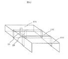
複数台の薄型サーバ1は、図8に示すラック31に搭載される。図8は、ラック31から薄型サーバ1を前面側に引き出した状態を示している。
Embodiments of the present invention will be described below with reference to the drawings.
FIG. 1 is a view showing an internal mounting structure of a thin server, and FIG. 2 is an external view thereof. 3 shows the appearance of the server covered with the
A plurality of
図1〜図4において、2はマザーボード、3はCPU、4はメモリ、5はチップセット、6はPCIライザーカード、7はHDD、8はCD−ROMドライブ、9はFDドライブ、10はフロントパネルボード、11はファンユニット、12はHDDバックボード、13はCD−ROMケーブル、14はFDDケーブル、15はフロントパネルボードケーブル、16aは電源(標準側)、16bは電源(増設側)、17は電源バックボード、18は電源ケーブル、19はケーブルダクト、20は背面コネクタ類、21は背面ケーブル類、22はPCIボードスロット、24はケーブル、25(図6)はマザーボード側ケーブルコネクタ、26はHDDバックボード側コネクタ、27は前部天板、28は後部天板、30はラックイヤーである。前面にはフロントべゼル29(図2)を有している。
1-4, 2 is a motherboard, 3 is a CPU, 4 is a memory, 5 is a chipset, 6 is a PCI riser card, 7 is an HDD, 8 is a CD-ROM drive, 9 is an FD drive, and 10 is a front panel. Board, 11 fan unit, 12 HDD backboard, 13 CD-ROM cable, 14 FDD cable, 15 front panel board cable, 16a power supply (standard side), 16b power supply (expansion side), 17 Power supply backboard, 18 is a power cable, 19 is a cable duct, 20 is a back connector, 21 is a back cable, 22 is a PCI board slot, 24 is a cable, 25 (FIG. 6) is a motherboard side cable connector, and 26 is a HDD. A
図3及び図4は図1の構造に対して後部天板28で覆った状態を示し、いずれも筐体を途中から伸ばした状態である。ただしフロントベゼル29を外してある。図5は図2の状態にあるサーバ1の内部構造図であり、伸ばした状態(図1)から収納状態(元の状態)に戻した状態を示している。
FIGS. 3 and 4 show a state in which the structure of FIG. 1 is covered with a
本実施例で特徴的なことは、マザーボード2は、CPU3、メモリ4、チップセット5、PCIライザーカード6、及び電源16a,16b等を実装しており、HDDバックボード12は、HDD7、CD−ROMドライブ8、FDドライブ9、フロントパネルボード10及びファンユニット11を実装している。ここで、HDDバックボード12は、マザーボード2に対して前面側に引き出し可能な構造となっている。HDDバックボード12とマザーボード2は、コネクタ26,25を備え、これらのコネクタ25,26にはケーブル24が接続されている。また、ケーブル24を覆ってそれを保護するために伸縮可能なケーブルダクト19が実装される。これについては、図6以降の図面を参照して詳説される。
What is characteristic in the present embodiment is that the
図6は図5の上部平面図である。この状態は、前部天板27が後部天板28の下側に収納され、HDDバックボード12が収納された状態である。ケーブルダクト19は縮んだ状態にある。図7は図6の状態からHDDバックボード12が前面側に引き出された状態であり、ケーブルダクト19が伸びた状態になる。ケーブルダクト19内のケーブル24も伸びた状態になる。
6 is a top plan view of FIG. In this state, the
図9〜図12はケーブルダクト19の構成を示す。ケーブルダクト19は数段構造、例えば3段
構造になっており、図11、12に示すように、箱型形状の箱の大きさが順に異なる3つのダクト191、192,193から構成される。ダクト191の上端部Aは固定部となるマザーボード2側に固定され、大きいダクト193の下端部Bは可動するHDDバックボード12に固定される。移動する側の大きい方のダクト193,192は、小さい方のダクト192,191を覆って入り込む構造である。
9 to 12 show the configuration of the
更に、ケーブルダクト191内には2本のピン23が直立して固定されている。ピン23はケーブル24の余長処理を考慮した空間を形成する。
図13及び14はケーブルダクト19内のケーブル24を配線した状態を示す。ケーブル24は2つのピン23の間を通って案内され、マザーボード側コネクタ25とHDDバックボード側コネクタ26に接続される。ケーブル24は2つのピン23の間を通って伸びた状態になる。HDDバックボード12を引き伸ばした状態から元に戻すと、ケーブルダクト19及びケーブルダクト19内のケーブル24は縮んで、図13のように、ダクト191内に収納される状態になる。
Further, two
13 and 14 show a state in which the
図9〜図13に示すように、本実施例では、2本のピン23はケーブルダクト19のやや左側に設置して、ケーブルダクト19内の右側に大きな空間を設けることによってケーブル24の余長処理をしている。ここで、ピン23の位置はケーブルダクト19内の左右どちらでもよいが、どちらか一方に寄らせることによりケーブル24の余長処理の空間を確保することができる。また、ケーブル24としてはシリアルATAケーブルのようなフレキシブルなケーブルを使用することにより、スムーズにケーブルダクト19内のケーブル24を余長処理することができる。
As shown in FIGS. 9 to 13, in this embodiment, the two
薄型サーバでは狭い筐体内にCPU3等の発熱部を搭載するので、筐体内部の温度が上昇する。そこで、装置内部を冷却するために、強力なファンユニット11が必要となる。しかるに、筐体を引き伸ばすだけでは、CPU3等の冷却が不十分になる可能性がある。
本発明の実施例によれば、前部天板27で装置の伸ばした部分を覆うような構造にすることにより、装置の上へファンユニット11の冷却風は逃げないので、冷却効率は向上する。また、装置の保守や故障時には、前部天板27を開けて作業を行なうことができる。
In a thin server, since a heat generating part such as the
According to the embodiment of the present invention, the cooling efficiency of the
図1及び図7のようにケーブルダクト19を伸ばした状態では、ファンユニット11からの冷却風がCPU3側と電源16側に分けられるので、効率的に装置内を冷却することができる。すなわちケーブルダクト19が冷却風の仕切り板の役割を果たす。
サーバの保守作業等は、図8のように、ラック31からサーバの装置を引き出して、前部天板27を開けた状態で、例えばファンユニット11やHDDバックボード12など故障箇所の保守を行なうことができる。
In the state where the
As shown in FIG. 8, the server maintenance work or the like is performed by, for example, performing maintenance on a faulty part such as the
薄型サーバ1の背面に接続された背面ケーブル類21についても、ラック31に数多くのサーバが搭載されるので、ケーブル類21に余長を持たせた又はケーブル類21をアームに固定してアームを伸び縮みできるようにしたとしても、ケーブル配線が複雑になりケーブル類21が装置背面のコネクタ20から抜ける可能性又はケーブル類21が絡まる可能性がある。しかるに、本実施例では、装置の後部はラック31に固定されているので、装置背面のケーブル類21が抜ける可能性や絡まる可能性はない。
As for the
以上、一実施例について説明したが、本発明は薄型サーバへの適用に限定されるものではない。ラックに収納され、ラックから引き出し可能な電子ユニットであれば、サーバ以外にも適用可能である。 Although one embodiment has been described above, the present invention is not limited to application to a thin server. Any electronic unit that is housed in a rack and can be pulled out from the rack can be applied to devices other than servers.
1:薄型サーバ 2:マザーボード 3:CPU 4:メモリ 5:チップセット 6:PCIライザーカード 7:HDD 8:CD−ROMドライブ 9:FDドライブ 10:フロントパネルボード 11:ファンユニット 12:HDDバックボード 13:CD−ROMケーブル 14:FDDケーブル 15:フロントパネルボードケーブル 16a:電源(標準側) 16b:電源(増設側) 17:電源バックボード 18:電源ケーブル 19:ケーブルダクト 20:背面コネクタ類 21:背面ケーブル類 22:PCIボードスロット 23:ピン 24:ケーブル 25:マザーボード側コネクタ 26:HDDバックボード側コネクタ 27:前部天板 28:後部天板 29:フロントベゼル 30:ラックイヤー 31:ラック 191:長穴
1: Thin server 2: Motherboard 3: CPU 4: Memory 5: Chipset 6: PCI riser card 7: HDD 8: CD-ROM drive 9: FD drive 10: Front panel board 11: Fan unit 12: HDD backboard 13 : CD-ROM cable 14: FDD cable 15: Front
Claims (5)
ある種の電子部品を実装した第1のボードと、該第1のボードに対して該装置の前面側に引き出し可能に構成された、ある種の電子部品を実装した第2のボードと、該第1のボードと該第2のボードにそれぞれの端部が接続されたケーブルと、を備え、該第1のボードに対して該第2のボードを前面側に引き出すとき、該第1のボード側の該ケーブルの接続部を固定した状態で、該第2のボードを引き出すことを特徴とする電子装置。 A thin electronic device mounted with electronic components mounted in a state that can be pulled out to a rack,
A first board on which a certain type of electronic component is mounted; a second board on which a certain type of electronic component is mounted; and a second board configured to be able to be pulled out to the front side of the apparatus with respect to the first board; A first board and a cable connected at each end to the second board, and when the second board is pulled out to the front side with respect to the first board, the first board An electronic device, wherein the second board is pulled out in a state where the connecting portion of the cable on the side is fixed.
ある種の電子部品を実装した第1のボードと、該第1のボードに対して該装置の前面側に引き出し可能に構成された、ある種の電子部品を実装した第2のボードと、該第1のボードと該第2のボードにそれぞれの端部が接続されたケーブルと、該ケーブルを覆って保護し、かつ該第2のボードを引き出し又は元に戻す動作に応じて伸縮可能な構造に構成されたケーブルダクト、とを備えたことを特徴とする電子装置。 A thin electronic device mounted with electronic components mounted in a state that can be pulled out to a rack,
A first board on which a certain type of electronic component is mounted; a second board on which a certain type of electronic component is mounted; and a second board configured to be able to be pulled out to the front side of the apparatus with respect to the first board; A first board and a cable each having an end connected to the second board, and a structure that covers and protects the cable and can be expanded and contracted in accordance with an operation of pulling out or returning the second board An electronic device comprising: a cable duct configured as described above.
The plurality of pins are provided upright at an asymmetrical position when viewed from the front of the device so as to secure an extra length portion of the cable in a wider space formed by the pins and the inner wall of the cable duct. The electronic device according to claim 1, wherein the cable is guided.
Priority Applications (1)
| Application Number | Priority Date | Filing Date | Title |
|---|---|---|---|
| JP2006000643A JP2007183735A (en) | 2006-01-05 | 2006-01-05 | Electronic device |
Applications Claiming Priority (1)
| Application Number | Priority Date | Filing Date | Title |
|---|---|---|---|
| JP2006000643A JP2007183735A (en) | 2006-01-05 | 2006-01-05 | Electronic device |
Publications (1)
| Publication Number | Publication Date |
|---|---|
| JP2007183735A true JP2007183735A (en) | 2007-07-19 |
Family
ID=38339782
Family Applications (1)
| Application Number | Title | Priority Date | Filing Date |
|---|---|---|---|
| JP2006000643A Pending JP2007183735A (en) | 2006-01-05 | 2006-01-05 | Electronic device |
Country Status (1)
| Country | Link |
|---|---|
| JP (1) | JP2007183735A (en) |
Cited By (4)
| Publication number | Priority date | Publication date | Assignee | Title |
|---|---|---|---|---|
| JP2017153180A (en) * | 2016-02-22 | 2017-08-31 | 富士通株式会社 | Cable holder |
| JP2018073212A (en) * | 2016-10-31 | 2018-05-10 | 富士通株式会社 | Cable unit and server device |
| US10051760B2 (en) | 2014-10-30 | 2018-08-14 | Fujitsu Component Limited | KVM switch, mounting bracket and system |
| WO2020095740A1 (en) * | 2018-11-09 | 2020-05-14 | Necプラットフォームズ株式会社 | Electronic device and maintenance method for electronic device |
-
2006
- 2006-01-05 JP JP2006000643A patent/JP2007183735A/en active Pending
Cited By (7)
| Publication number | Priority date | Publication date | Assignee | Title |
|---|---|---|---|---|
| US10051760B2 (en) | 2014-10-30 | 2018-08-14 | Fujitsu Component Limited | KVM switch, mounting bracket and system |
| US10264702B2 (en) | 2014-10-30 | 2019-04-16 | Fujitsu Component Limited | KVM switch, mounting bracket and system |
| JP2017153180A (en) * | 2016-02-22 | 2017-08-31 | 富士通株式会社 | Cable holder |
| JP2018073212A (en) * | 2016-10-31 | 2018-05-10 | 富士通株式会社 | Cable unit and server device |
| WO2020095740A1 (en) * | 2018-11-09 | 2020-05-14 | Necプラットフォームズ株式会社 | Electronic device and maintenance method for electronic device |
| JP2020077286A (en) * | 2018-11-09 | 2020-05-21 | Necプラットフォームズ株式会社 | Electronic apparatus, and maintenance method of electronic apparatus |
| US11547003B2 (en) | 2018-11-09 | 2023-01-03 | Nec Platforms, Ltd. | Electronic device and maintenance method for electronic device |
Similar Documents
| Publication | Publication Date | Title |
|---|---|---|
| US10372178B2 (en) | Flexible hot plug fan module system | |
| EP3506726B1 (en) | Hot pluggable fan system and connection apparatus | |
| US20070247804A1 (en) | High-density disk array device | |
| JP4108472B2 (en) | Disk array unit | |
| US10271460B2 (en) | Server system | |
| JP6164035B2 (en) | Hard disk drive mounting apparatus and information processing apparatus | |
| US20010046118A1 (en) | Data storage system | |
| JP2013045440A (en) | Device and system having storage device in lateral face accessible drive thread | |
| JP2002032153A (en) | Cartridge type server unit and casing for loading the same | |
| US8164900B2 (en) | Enclosure of electronic device | |
| JP2007179655A (en) | Disk array device | |
| JP2011527039A (en) | Drive box | |
| KR20150004239U (en) | Computer case | |
| US20090195978A1 (en) | Structure and method for electrically connecting heat dissipating device and adapting circuit board | |
| CN102147641A (en) | Electronic device | |
| JP2007183735A (en) | Electronic device | |
| JP2011040608A (en) | Rack plate for storing electronic device, storage rack including rack plate for storing electronic device, and electronic device stored on rack plate for storing electronic device | |
| TW202010377A (en) | server | |
| JP2003324292A (en) | Information processing unit | |
| TWI702895B (en) | Server case | |
| US8559177B2 (en) | Fan for computer element in the service position | |
| JP4159046B2 (en) | Fan unit | |
| JP6205177B2 (en) | Computer equipment | |
| US20240292521A1 (en) | Vibration dampening for high-density storage system structure | |
| TWI486118B (en) | Server rack |