JP2005188623A - Clip - Google Patents
Clip Download PDFInfo
- Publication number
- JP2005188623A JP2005188623A JP2003430282A JP2003430282A JP2005188623A JP 2005188623 A JP2005188623 A JP 2005188623A JP 2003430282 A JP2003430282 A JP 2003430282A JP 2003430282 A JP2003430282 A JP 2003430282A JP 2005188623 A JP2005188623 A JP 2005188623A
- Authority
- JP
- Japan
- Prior art keywords
- clip
- trunk
- panel
- frame
- mounting hole
- Prior art date
- Legal status (The legal status is an assumption and is not a legal conclusion. Google has not performed a legal analysis and makes no representation as to the accuracy of the status listed.)
- Pending
Links
Images


Landscapes
- Insertion Pins And Rivets (AREA)
Abstract
Description
本発明は、例えば自動車ボディのパネルにコネクタなどの被取付け部材を装着するときに使用するクリップに関するものである。 The present invention relates to a clip used when a member to be attached such as a connector is attached to a panel of an automobile body, for example.
コネクタなどの被取付け部材は、自動車ボディのパネルに合成樹脂製のクリップで装着されている。この種のクリップは、被取付け部材を取付ける取付け部と、パネルに設けられた取付け孔に挿入することにより所定の保持力でこのパネルに係止される係合部とを備えている。係合部は、前記取付け孔に挿入された係合部の抜け出る側の前記取付け孔の縁に引掛る鋸刃状の引掛りを備えているものがある(例えば、特許文献1)。
自動車ボディのパネルにコネクタなどの被取付け部材を装着するための従来のクリップは、係合部をパネルに開けられた取付け孔に挿通させることによって、係合部に形成された鋸刃状の引掛りが取付け孔の縁に引掛ることによって固定される。ところが、例えばトラック等のパネルはその厚さが10mm程度と厚く、このパネルの取付け孔の縁の角に丸みまたは面取りができ、この丸みまたは面取りで引掛り代が確保できにくくなり、引掛りの保持力が働きにくくなる。さらに、パネルの取付け孔の縁の丸みまたは面取りは、パネルが厚くなる程でき易いので、クリップを適用できるパネルの厚さの範囲は狭いものとなる。
そこで、本発明の課題は、適用できるパネルの厚さの範囲の広いクリップを提供することである。
A conventional clip for mounting a member such as a connector on a panel of an automobile body has a saw blade-like hook formed on the engaging portion by inserting the engaging portion into a mounting hole formed in the panel. Is fixed by hooking the edge of the mounting hole. However, for example, a panel such as a truck is as thick as about 10 mm, and the edge of the mounting hole of this panel can be rounded or chamfered, and it becomes difficult to secure a catching margin due to this rounding or chamfering. Holding power becomes difficult to work. Further, since the roundness or chamfering of the edge of the mounting hole of the panel is more easily performed as the panel becomes thicker, the range of the panel thickness to which the clip can be applied becomes narrower.
Accordingly, an object of the present invention is to provide a clip having a wide range of applicable panel thicknesses.
上記課題を解決するため、請求項1記載の発明は、自動車のパネルに被取付部材を装着するための合成樹脂製のクリップであって、前記被取付け部材を取り付けることができる取付け部と、前記パネルに設けられた取付け孔に挿通することにより、このパネルに取り付けられる係合部とを備え、この係合部は、前記取付け孔に挿通可能な幹部と、この幹部の長さ方向に関して複数段にわたって設けられた係止爪とを備え、各係止爪は、その自由状態で前記幹部の外周面から外方向へ突出し、その状態で前記取付け孔の縁に係止可能な係止部を有するクリップである。
このように、係合部において複数段の係止爪を設けることにより、広範囲の板厚のパネルに対応できるにもかかわらず、個々の係止爪が独立していることから、各係止爪の係止部を取付け孔の縁に係止させることができる。これにより、広範囲の板厚のパネルの取付け孔にクリップを係止させることができる。
In order to solve the above-mentioned problem, the invention according to
In this way, by providing a plurality of stages of locking claws in the engaging portion, each locking claw is independent of each other, although it can accommodate a wide range of panel thickness panels. Can be locked to the edge of the mounting hole. Thereby, a clip can be latched in the attachment hole of a panel with a wide range of plate thickness.
さらに、請求項2記載の発明は、請求項1記載の発明において、係合部の各係止爪は、個々に左右で対をなしているとともに、幹部の長さ方向に関して隣合う係止爪は、互いに幹部の周方向へずらせて配置されていることである。
このように、各係止爪が対をなしていることにより、パネルの取付け孔に対する係止爪の係止状態がより安定するとともに、幹部の長さ方向に関して隣合う係止爪を周方向へずらせることで、一定長さの幹部において、より多くの係止爪を多段に配置することができる。したがって、多種類の板厚のパネルにクリップを係止させることができる。
Further, the invention according to
In this way, each locking claw makes a pair, so that the locking state of the locking claw with respect to the mounting hole of the panel becomes more stable, and the adjacent locking claw in the length direction of the trunk portion extends in the circumferential direction. By shifting the position, more locking claws can be arranged in multiple stages on the trunk portion of a certain length. Therefore, it is possible to lock the clip to a panel having various plate thicknesses.
請求項1記載の発明によれば、広範囲の板厚のパネルの取付け孔にクリップを係止させることができる。
さらに、請求項2記載の発明によれば、請求項1記載の発明の効果とともに、より多くの係止爪を多段に配置できるので、多種類の板厚のパネルにクリップを係止させることができる。
According to the first aspect of the present invention, the clip can be locked in the mounting hole of the panel having a wide range of plate thickness.
Furthermore, according to the invention described in
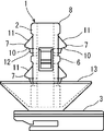
以下、図面を参照して本発明を実施するための最良の形態を説明する。図1はこの実施の形態のクリップの正面を示し、図2は図1のクリップの右側面を示し、図3は図1のクリップの平面を示し、図4は図3のクリップのIV−IV断面をクリップの使用状態で示す。これらの図に示されているようにクリップ1は、係合部2と取付け部3とからなる合成樹脂による一体成形物である。係合部2は、例えば図4に示されているトラックボディのフレーム4に形成された円形の取付け孔5に挿入される部分であり、取付け部3は、車両に内装されるコネクタなど被取付け部材(図示しない)を取付ける部分である。
The best mode for carrying out the present invention will be described below with reference to the drawings. 1 shows the front of the clip of this embodiment, FIG. 2 shows the right side of the clip of FIG. 1, FIG. 3 shows the plane of the clip of FIG. 1, and FIG. 4 shows the IV-IV of the clip of FIG. The cross section is shown with the clip in use. As shown in these drawings, the
係合部2は、図1、2に示すように幹部6と、幹部6に一体の複数段の係止爪7を備え、各係止爪7は互いに独立している。幹部6の基部は係合部2の基部であり、図3に示すように幹部6の先端部分8は、その端面が円環状になっており、係合部2を取付け孔5に挿入するときの位置ずれなどを補正する機能を備えている。
As shown in FIGS. 1 and 2, the
図4によっても明らかなように幹部6は、取付け孔5を挿通できる太さと、取付け孔5より突き出す軸方向長さを有する中空円筒状に形成されている。係止爪7は個々に左右で対をなしているとともに、幹部6の長さ方向に関して隣合う係止爪7は、互いに幹部6の周方向へずらせて配置されている。そして、係止爪7の互いに反対方向を向いた一対を一組として三組の係止爪7が設けられ、幹部6の先端部分8側から基部にかけて間隔をおいて三段が構成されている。各係止爪7の断面形状は、図4に示すように変形三角形状をしている。各係止爪7の基部は、幹部6と一体の結合部分となっており、この部分が若干肉薄のセルフヒンジ9となっている。
As is apparent from FIG. 4, the
図1、2に示すように、各係止爪7の両側端と先端は、幹部6と分離していて、各係止爪7全体はセルフヒンジ9において幹部6の内方へ全体が弾性撓みすることができる。
図4に示すように各係止爪7は、自由状態では幹部6の外周面より外方向へ突出し、取付け孔5の縁5aに係止まる係止部10と幹部6の基部方向に対して幹部6の外方に傾斜した傾斜面11とを備えている。係止爪7の外方向への突出は、取付け孔5の縁5aに丸みまたは面取りができていても、係止爪7の係止部10がその丸みまたは面取りを越えて所定の保持力を得られる寸法に設定されている。係止部10は、幹部6の中心軸に対してほぼ直角の平面に構成され、それに続く裾部12と鈍角(概ね135度)をなして結合している。各係止爪7は、傾斜面11に外方からの力を受けるとセルフヒンジ9において、幹部6の外周面の位置まで弾性撓みする。
As shown in FIGS. 1 and 2, both side ends and the tip of each
As shown in FIG. 4, each
幹部6の基部には、基部から一体に先端側に先広がりに外方向へ大きく広がった皿状のスタビライザ13が形成されている。このスタビライザ13には、図3に示すように対向する二箇所に半径方向に広がる略V字状のスリット14が形成されている。そして、図4に示すように、このスタビライザ13は、係合部2をフレーム4の一方の面4aから取付け孔5に挿入したときに、フレーム4の一方の面4aに押されて弾性変形しながらフレーム4の一方の面4aに接触する構造であり、スリット14を備えることにより、成形性が向上し、弾性変形もし易く、フレーム4の一方の面4aへの密着性も向上する。
A plate-
このクリップ1は、その係合部2をフレーム4の取付け孔5に挿入することにより、フレーム4に固定され、取付け部3に対してコネクタなどの被取付け部材を取付けることができる。幹部6の先端側から取付け孔5に挿入していくことにより、係合部2の係止爪7がその傾斜面11を取付け孔5により外方から押付けられ、そのセルフヒンジ9において幹部6の外径まで弾性撓みして他方の面4b側の縁5aから抜出す。抜出した係止爪7は、自由状態となり、弾性力で復帰して幹部6より半径方向に大きく突出し、取付け孔5の縁5aに丸みまたは面取りがあっても、係止部10によって縁5aに係止されて固定される。
The
さらに、係合部2において複数段の係止爪7を設けることにより、広範囲の板圧のフレーム4に対応できるにもかかわらず、個々の係止爪7が独立していることから、各係止爪7の係止部10を取付け孔5の縁5aに係止させることができる。具体的には以下のようになる。フレーム4の厚さが厚い場合、図4の図示中段と下段の係止爪7は、取付け孔5内で弾性撓みしたまま取付け孔5内に止まる。この係止に作用しない係止爪7も、取付け孔5に弾性力を作用し続け、幹部6の位置を安定させる。厚さの中位のフレーム4に対しては、中段の係止爪7が働くことになり、それより厚さの薄いフレーム4には、下段の係止爪7が働くことになる。いずれの場合も、スタビライザ13がフレーム4の一方の面4aに密着してその弾性力を係止爪7の係止部10をフレーム4の他方の面4b側の取付け孔5の縁5aに押付けるように働くため、フレーム4への固定状態が確実に維持される。
さらに、スタビライザ13自体にも板厚吸収作用がある。例えば図4において、フレーム4の板厚に多少の変化があった場合、その変化はスタビライザ13の撓み量が変わることによって吸収される。そして、スリット14はスタビライザ13を広範囲に撓ませて板厚吸収するためのものである。このようなスタビライザ13の機能は、各係止爪7においても同様に発揮されるので、各係止爪7とスタビライザ13の組合せにより、クリップ1が適応する範囲においては、無段階に等しい板厚変化に対処できる。
さらに、各係止爪7が対をなしていることにより、フレーム4の取付け孔5に対する係止爪7の係止状態がより安定するとともに、幹部6の長さ方向に関して隣合う係止爪7を周方向へずらせることで、一定長さの幹部6において、より多くの係止爪7を多段に配置することができる。
Furthermore, by providing a plurality of stages of latching
Further, the
Furthermore, since each latching
なお、上記実施の形態は三段の係止爪7を備えているが、これに限定されず、多種の板厚のフレーム4に適用できるようにするには、係止爪7の段数を多段にすればよい。
Although the above embodiment includes the three-
本発明は、自動車産業等において、パネルに係止するクリップの使用可能範囲を著しく広くすることができる。 The present invention can remarkably widen the usable range of a clip to be locked to a panel in the automobile industry or the like.
1 クリップ
2 係合部
3 取付け部
4 フレーム
5 取付け孔
5a 縁
6 幹部
7 係止爪
10 係止部
DESCRIPTION OF
Claims (2)
2. The clip according to claim 1, wherein the engaging claws of the engaging portion are individually paired on the right and left sides, and the engaging claws adjacent to each other in the length direction of the trunk portion are mutually circumferential in the trunk portion. A clip placed in a slanted manner.
Priority Applications (1)
| Application Number | Priority Date | Filing Date | Title |
|---|---|---|---|
| JP2003430282A JP2005188623A (en) | 2003-12-25 | 2003-12-25 | Clip |
Applications Claiming Priority (1)
| Application Number | Priority Date | Filing Date | Title |
|---|---|---|---|
| JP2003430282A JP2005188623A (en) | 2003-12-25 | 2003-12-25 | Clip |
Publications (1)
| Publication Number | Publication Date |
|---|---|
| JP2005188623A true JP2005188623A (en) | 2005-07-14 |
Family
ID=34788697
Family Applications (1)
| Application Number | Title | Priority Date | Filing Date |
|---|---|---|---|
| JP2003430282A Pending JP2005188623A (en) | 2003-12-25 | 2003-12-25 | Clip |
Country Status (1)
| Country | Link |
|---|---|
| JP (1) | JP2005188623A (en) |
Cited By (7)
| Publication number | Priority date | Publication date | Assignee | Title |
|---|---|---|---|---|
| JP2007147017A (en) * | 2005-11-29 | 2007-06-14 | Furukawa Electric Co Ltd:The | Fastener |
| JP2009156329A (en) * | 2007-12-26 | 2009-07-16 | Nippon Pop Rivets & Fasteners Ltd | Internal thread hole closing plug |
| JP2009293798A (en) * | 2008-05-07 | 2009-12-17 | Nifco Inc | Fastener |
| DE102013014996A1 (en) * | 2013-09-11 | 2015-03-12 | GM Global Technology Operations, LLC (n.d. Ges. d. Staates Delaware) | Fixing element for pre-assembly of body components |
| JP2016223627A (en) * | 2015-05-27 | 2016-12-28 | リシー エアロスペース | Plastic lining fastener |
| JP2020172951A (en) * | 2019-04-08 | 2020-10-22 | 劉 怡汝 | Coupling tool |
| JP2021057211A (en) * | 2019-09-30 | 2021-04-08 | 株式会社内田洋行 | Wiring connection device |
Citations (3)
| Publication number | Priority date | Publication date | Assignee | Title |
|---|---|---|---|---|
| JPS5012168U (en) * | 1973-05-30 | 1975-02-07 | ||
| JPS62163317U (en) * | 1986-03-31 | 1987-10-17 | ||
| JPH04165113A (en) * | 1990-10-30 | 1992-06-10 | Kinugawa Rubber Ind Co Ltd | Clip |
-
2003
- 2003-12-25 JP JP2003430282A patent/JP2005188623A/en active Pending
Patent Citations (3)
| Publication number | Priority date | Publication date | Assignee | Title |
|---|---|---|---|---|
| JPS5012168U (en) * | 1973-05-30 | 1975-02-07 | ||
| JPS62163317U (en) * | 1986-03-31 | 1987-10-17 | ||
| JPH04165113A (en) * | 1990-10-30 | 1992-06-10 | Kinugawa Rubber Ind Co Ltd | Clip |
Cited By (10)
| Publication number | Priority date | Publication date | Assignee | Title |
|---|---|---|---|---|
| JP2007147017A (en) * | 2005-11-29 | 2007-06-14 | Furukawa Electric Co Ltd:The | Fastener |
| JP2009156329A (en) * | 2007-12-26 | 2009-07-16 | Nippon Pop Rivets & Fasteners Ltd | Internal thread hole closing plug |
| JP2009293798A (en) * | 2008-05-07 | 2009-12-17 | Nifco Inc | Fastener |
| DE102013014996A1 (en) * | 2013-09-11 | 2015-03-12 | GM Global Technology Operations, LLC (n.d. Ges. d. Staates Delaware) | Fixing element for pre-assembly of body components |
| JP2016223627A (en) * | 2015-05-27 | 2016-12-28 | リシー エアロスペース | Plastic lining fastener |
| CN106567878A (en) * | 2015-05-27 | 2017-04-19 | 利西太空公司 | Plastic lining fasteners |
| CN106567878B (en) * | 2015-05-27 | 2019-04-23 | 利西太空公司 | Plastic bushing fastener |
| JP2020172951A (en) * | 2019-04-08 | 2020-10-22 | 劉 怡汝 | Coupling tool |
| JP2021057211A (en) * | 2019-09-30 | 2021-04-08 | 株式会社内田洋行 | Wiring connection device |
| JP7316174B2 (en) | 2019-09-30 | 2023-07-27 | 株式会社内田洋行 | Wiring connection device |
Similar Documents
| Publication | Publication Date | Title |
|---|---|---|
| US8914952B2 (en) | Clip | |
| JP5243749B2 (en) | Clip and support member | |
| US20140042704A1 (en) | Seal aligning and retaining assembly and method of retaining a seal | |
| JP4213550B2 (en) | clip | |
| JP2010151174A (en) | Clip | |
| EP1717457B1 (en) | Fastening system | |
| WO2015060074A1 (en) | Corrugated-tube band-clip mounting structure | |
| JP2005188623A (en) | Clip | |
| JP2011091948A (en) | Corrugated clamp | |
| JP6546699B2 (en) | clip | |
| JP2008223918A (en) | Anchor | |
| JP2005133783A (en) | Clip | |
| JP5886066B2 (en) | clip | |
| JP2008190606A (en) | Anchor | |
| JP3554591B2 (en) | Band clip for mounting long objects | |
| JP7280813B2 (en) | Fastener | |
| JP2007215353A (en) | Attachment fixture | |
| JP2005228582A (en) | Grommet | |
| JP2007155007A (en) | Member fixing clip structure | |
| CN111791971B (en) | Clip assembly for retaining components during a vehicle assembly/disassembly process | |
| JP5095550B2 (en) | clip | |
| JP2009201179A (en) | Grommet | |
| JPH1172108A (en) | Part mounting clip | |
| JP4259383B2 (en) | Clip mounting structure to grommet | |
| JP6125307B2 (en) | Insertion member |
Legal Events
| Date | Code | Title | Description |
|---|---|---|---|
| A621 | Written request for application examination |
Free format text: JAPANESE INTERMEDIATE CODE: A621 Effective date: 20061222 |
|
| A977 | Report on retrieval |
Free format text: JAPANESE INTERMEDIATE CODE: A971007 Effective date: 20090129 |
|
| A131 | Notification of reasons for refusal |
Free format text: JAPANESE INTERMEDIATE CODE: A131 Effective date: 20090804 |
|
| A521 | Written amendment |
Free format text: JAPANESE INTERMEDIATE CODE: A523 Effective date: 20090930 |
|
| A02 | Decision of refusal |
Free format text: JAPANESE INTERMEDIATE CODE: A02 Effective date: 20100615 |