JP2004167669A - Control device - Google Patents
Control device Download PDFInfo
- Publication number
- JP2004167669A JP2004167669A JP2003335393A JP2003335393A JP2004167669A JP 2004167669 A JP2004167669 A JP 2004167669A JP 2003335393 A JP2003335393 A JP 2003335393A JP 2003335393 A JP2003335393 A JP 2003335393A JP 2004167669 A JP2004167669 A JP 2004167669A
- Authority
- JP
- Japan
- Prior art keywords
- setting
- screen
- control device
- password
- registrant
- Prior art date
- Legal status (The legal status is an assumption and is not a legal conclusion. Google has not performed a legal analysis and makes no representation as to the accuracy of the status listed.)
- Granted
Links
- 238000001746 injection moulding Methods 0.000 claims description 24
- 238000004519 manufacturing process Methods 0.000 claims description 8
- 210000003462 vein Anatomy 0.000 claims description 6
- 238000001125 extrusion Methods 0.000 claims description 4
- 238000004512 die casting Methods 0.000 claims description 2
- 239000004065 semiconductor Substances 0.000 claims description 2
- 238000000465 moulding Methods 0.000 description 33
- 238000003860 storage Methods 0.000 description 26
- 230000006870 function Effects 0.000 description 15
- 238000000034 method Methods 0.000 description 10
- 238000012790 confirmation Methods 0.000 description 9
- 238000010586 diagram Methods 0.000 description 8
- 238000003825 pressing Methods 0.000 description 7
- 238000013500 data storage Methods 0.000 description 6
- 238000012544 monitoring process Methods 0.000 description 6
- 238000002347 injection Methods 0.000 description 4
- 239000007924 injection Substances 0.000 description 4
- 230000002950 deficient Effects 0.000 description 3
- 238000012217 deletion Methods 0.000 description 3
- 230000037430 deletion Effects 0.000 description 3
- 210000005252 bulbus oculi Anatomy 0.000 description 1
- 238000001816 cooling Methods 0.000 description 1
- 230000007547 defect Effects 0.000 description 1
- 238000001514 detection method Methods 0.000 description 1
- 238000003745 diagnosis Methods 0.000 description 1
- 239000004973 liquid crystal related substance Substances 0.000 description 1
- 238000007726 management method Methods 0.000 description 1
- 238000012986 modification Methods 0.000 description 1
- 230000004048 modification Effects 0.000 description 1
- 238000005303 weighing Methods 0.000 description 1
Images


Classifications
-
- G—PHYSICS
- G05—CONTROLLING; REGULATING
- G05B—CONTROL OR REGULATING SYSTEMS IN GENERAL; FUNCTIONAL ELEMENTS OF SUCH SYSTEMS; MONITORING OR TESTING ARRANGEMENTS FOR SUCH SYSTEMS OR ELEMENTS
- G05B19/00—Programme-control systems
- G05B19/02—Programme-control systems electric
- G05B19/18—Numerical control [NC], i.e. automatically operating machines, in particular machine tools, e.g. in a manufacturing environment, so as to execute positioning, movement or co-ordinated operations by means of programme data in numerical form
- G05B19/409—Numerical control [NC], i.e. automatically operating machines, in particular machine tools, e.g. in a manufacturing environment, so as to execute positioning, movement or co-ordinated operations by means of programme data in numerical form characterised by using manual data input [MDI] or by using control panel, e.g. controlling functions with the panel; characterised by control panel details or by setting parameters
-
- B—PERFORMING OPERATIONS; TRANSPORTING
- B29—WORKING OF PLASTICS; WORKING OF SUBSTANCES IN A PLASTIC STATE IN GENERAL
- B29C—SHAPING OR JOINING OF PLASTICS; SHAPING OF MATERIAL IN A PLASTIC STATE, NOT OTHERWISE PROVIDED FOR; AFTER-TREATMENT OF THE SHAPED PRODUCTS, e.g. REPAIRING
- B29C37/00—Component parts, details, accessories or auxiliary operations, not covered by group B29C33/00 or B29C35/00
- B29C2037/90—Measuring, controlling or regulating
- B29C2037/906—Measuring, controlling or regulating using visualisation means or linked accessories, e.g. screens, printers
-
- B—PERFORMING OPERATIONS; TRANSPORTING
- B29—WORKING OF PLASTICS; WORKING OF SUBSTANCES IN A PLASTIC STATE IN GENERAL
- B29C—SHAPING OR JOINING OF PLASTICS; SHAPING OF MATERIAL IN A PLASTIC STATE, NOT OTHERWISE PROVIDED FOR; AFTER-TREATMENT OF THE SHAPED PRODUCTS, e.g. REPAIRING
- B29C45/00—Injection moulding, i.e. forcing the required volume of moulding material through a nozzle into a closed mould; Apparatus therefor
- B29C45/17—Component parts, details or accessories; Auxiliary operations
- B29C45/76—Measuring, controlling or regulating
- B29C2045/7606—Controlling or regulating the display unit
-
- G—PHYSICS
- G05—CONTROLLING; REGULATING
- G05B—CONTROL OR REGULATING SYSTEMS IN GENERAL; FUNCTIONAL ELEMENTS OF SUCH SYSTEMS; MONITORING OR TESTING ARRANGEMENTS FOR SUCH SYSTEMS OR ELEMENTS
- G05B2219/00—Program-control systems
- G05B2219/30—Nc systems
- G05B2219/36—Nc in input of data, input key till input tape
- G05B2219/36542—Cryptography, encrypt, access, authorize with key, code, password
-
- G—PHYSICS
- G05—CONTROLLING; REGULATING
- G05B—CONTROL OR REGULATING SYSTEMS IN GENERAL; FUNCTIONAL ELEMENTS OF SUCH SYSTEMS; MONITORING OR TESTING ARRANGEMENTS FOR SUCH SYSTEMS OR ELEMENTS
- G05B2219/00—Program-control systems
- G05B2219/30—Nc systems
- G05B2219/45—Nc applications
- G05B2219/45244—Injection molding
Landscapes
- Engineering & Computer Science (AREA)
- Human Computer Interaction (AREA)
- Manufacturing & Machinery (AREA)
- Physics & Mathematics (AREA)
- General Physics & Mathematics (AREA)
- Automation & Control Theory (AREA)
- Numerical Control (AREA)
- Injection Moulding Of Plastics Or The Like (AREA)
- Lock And Its Accessories (AREA)
Abstract
Description
本発明は、産業機械の制御装置に関する。 The present invention relates to a control device for an industrial machine.
一般的に、射出成形機の表示装置の表示面積は制限される。そこで、特許文献1(特開2001−145947号公報)には、多くの情報をメイン画面領域とサブ画面領域にほぼ同時に表示する射出成形機の表示装置が開示されている。 Generally, the display area of a display device of an injection molding machine is limited. Therefore, Patent Document 1 (Japanese Patent Application Laid-Open No. 2001-145947) discloses a display device of an injection molding machine that displays a large amount of information almost simultaneously in a main screen area and a sub screen area.
この特許文献1では、射出成形機のヒューマンインタフェース部である表示装置の画面は、2分割される。分割された画面のうち一方は、専用のメイン画面領域である。他方は、専用のサブ画面領域である。メイン画面領域には、射出成形機のコントローラ機能を操作可能なコントローラ機能スイッチと射出成形機の成形条件を設定可能な設定器とが備えられる。メイン画面領域には、モニタリングデータが表示される。サブ画面領域には、メイン画面領域から独立して随時表示したいモニタリングデータ等の各種データが表示される。
In
この射出成形機の表示装置では、サブ画面領域が表示されてもメイン画面領域が隠れない。また、この射出成形機の表示装置では、メイン画面領域とサブ画面領域とは、自由に組み合わせて表示できる。ユーザは、煩雑な操作を行うことなく必要な情報を画面に表示でき、射出成形機の成形条件の設定、運転状態などの確認を効率よく行うことができる。
特許文献1の射出成形機の表示装置では、成形条件を設定する場合のセキュリティに関して何ら考慮されていない。このため、射出成形機を使用するいかなるユーザであっても、成形条件の設定値を変更することができる。射出成形機の成形条件が何人でも自由に設定できるとすると、適切な設定値が変更されて信頼性の高い工作が困難になる、ユーザが代わる度に新たに設定が必要になる、など不便な場合がある。
In the display device of the injection molding machine of
本発明は、以上のような実情に鑑みてなされたもので、運転条件の設定についてセキュリティを強化する産業機械の制御装置を提供することを目的とする。 The present invention has been made in view of the above circumstances, and has as its object to provide a control device for an industrial machine that enhances security in setting operating conditions.
本発明を実現するにあたって講じた具体的手段について以下に説明する。 Specific means taken for realizing the present invention will be described below.
本発明の実施例は、産業機械を制御する制御装置において、ユーザが予め登録された登録者か否か判断する手段と、ユーザが登録者であると判断された場合に、登録者の操作に応じて、産業機械の一以上の運転条件に関して個別に設定許可状態と設定禁止状態とのうちの一方を選択する手段と、登録者から、設定許可状態が選択された運転条件についての設定を受け付ける設定手段とを具備する制御装置である。 An embodiment of the present invention provides a control device for controlling an industrial machine, a means for determining whether a user is a pre-registered registrant, and an operation for the registrant when the user is determined to be a registrant. Accordingly, means for individually selecting one of a setting permission state and a setting prohibition state with respect to one or more operation conditions of the industrial machine, and accepting, from a registrant, a setting for the operation condition in which the setting permission state is selected. The control device includes a setting unit.
本発明においては、産業機械の運転条件のセキュリティが強化される。 In the present invention, the security of the operating conditions of the industrial machine is enhanced.
以下、図面を参照しながら本発明の実施の形態について説明する。 Hereinafter, embodiments of the present invention will be described with reference to the drawings.
(第1の実施の形態)
本実施の形態では、予め登録された登録者のみが、産業機械の運転条件を設定することが可能な産業機械の制御装置について説明する。
(First Embodiment)
In the present embodiment, a description will be given of an industrial machine control device in which only a pre-registered registrant can set operating conditions of an industrial machine.
本実施の形態では、産業機械として射出成形機を例として説明する、しかしながら、産業機械は、射出成形機に限られず、例えば工作機械などの他の機械でもよい。産業機械の具体例としては、射出成形機、押出成形機、工作機械、ダイキャストマシン、ロボット、半導体製造装置、印刷機などがある。 In the present embodiment, an injection molding machine will be described as an example of an industrial machine. However, the industrial machine is not limited to an injection molding machine, and may be another machine such as a machine tool. Specific examples of the industrial machine include an injection molding machine, an extrusion molding machine, a machine tool, a die casting machine, a robot, a semiconductor manufacturing device, a printing machine, and the like.
また、本実施の形態では、産業機械の運転条件として成形条件を例として説明する。しかしながら、運転条件は、成形条件に限られず、他の条件でもよい。 Further, in the present embodiment, a description will be given of a molding condition as an example of an operating condition of an industrial machine. However, the operating conditions are not limited to the molding conditions, and may be other conditions.
図1は、本実施の形態に係る産業機械の制御装置の一例を示すブロック図である。 FIG. 1 is a block diagram illustrating an example of the control device for an industrial machine according to the present embodiment.
制御装置1は、射出成形機2を制御する。制御装置1は、表示装置3、入力設定部4、登録者認識部5、成形条件記憶部6を具備する。
The
表示装置3は、画面表示部7、タッチパネル8、ダイレクト画面選択部9、入力信号制御部10、メイン画面メモリ11、サブ画面メモリ12、画面制御部13、画面データ記憶部(例えばVRAM)14を具備する。
The
画面表示部7には、例えば液晶パネル等が用いられる。
For example, a liquid crystal panel or the like is used for the
タッチパネル8は、透明であり、画面表示部7に対して取り付けられる。
The
入力信号制御部10は、タッチパネル8からの信号とダイレクト画面選択部9からの信号、射出成形機2からの各種の検出信号を入力する。入力信号制御部10は、入力した信号を、画面制御部13又は入力設定部4に出力する。
The input
メイン画面メモリ11は、メイン画面データを格納する。
The
サブ画面メモリ12は、サブ画面データを格納する。
The
画面制御部13は、入力信号制御部10経由で画面表示を要求する信号を入力した場合、画面表示の要求信号に応じて、メイン画面メモリ11からメイン画面データを読み出すとともに、サブ画面メモリ12からサブ画面データを読み出す。
When a signal for requesting screen display is input via the input
画面制御部13は、メイン画面データとサブ画面データとに基づいて、画面データを作成し、画面データを画面データ記憶部14に記憶する。
The
また、画面制御部13は、登録者認識部5から入力するデータに基づいて画面データを作成し、作成した画面データを画面データ記憶部14に記憶する。
Further, the
画面表示部7は、画面データ記憶部14に記憶されている画面データを表示する。
The
入力設定部4は、例えばID(識別コード)及びパスワード(暗証コード)、成形条件の設定値などのような、成形条件及びそのセキュリティに関する情報をタッチパネル8、入力信号制御部10経由で入力する。
The
登録者認識部5は、登録者記憶部5a、画面設定部5b、判断部5c、選択部5d、設定部5e、履歴表示部5fを具備する。
The
登録者認識部5は、成形条件記憶部6に記憶されている成形条件を書き換える際に、ユーザが予め登録されている登録者か判断し、登録者と判断された場合に、登録者の操作に応じて成形条件に関して設定許可状態又は設定禁止状態を選択する。そして、登録者認識部5は、設定許可状態が選択されている場合に、ユーザからの成形条件の設定を受け付け、成形条件記憶部6に記憶されている成形条件の設定値を変更する。
When rewriting the molding conditions stored in the molding
登録者記憶部5aは、例えば、登録者のID及びパスワードなどのような、登録者の認識に用いられる登録者情報を記憶する。
The
また、登録者記憶部5aは、各登録者について、設定許可状態又は設定禁止状態を選択可能な画面を示す画面設定情報を記憶する。
The
また、登録者記憶部5aは、設定許可状態と設定禁止状態とのうちいずれの状態が選択されているかを示す情報を記憶する。
In addition, the
画面設定部5bは、入力設定部4経由で入力された信号に基づいて、画面設定情報を登録者記憶部5aに記憶する。
The screen setting unit 5b stores the screen setting information in the
判断部5cは、入力設定部4経由で入力されたユーザ情報と登録者記憶部5aに記憶されている登録者情報とに基づいて、ユーザが登録者であるか否か判断する。
The
例えば、判断部5cは、ユーザから入力されたIDとパスワードの双方が登録者のIDとパスワードと一致する場合、ユーザが登録者であると判断する。
For example, when both the ID and the password input by the user match the registrant's ID and password, the
選択部5dは、ユーザが登録者と判断された場合に、入力設定部4経由で入力した登録者の操作内容に応じて、成形条件に関する設定許可状態と設定禁止状態とのうちの一方を選択し、選択された状態を示す情報を登録者記憶部5aに記憶する。また、選択部5dは、登録者記憶部5aの画面設定情報に基づいて、登録者が設定許可状態又は設定禁止状態を選択可能と設定された画面について状態の選択を受け付ける。
When the user is determined to be a registrant, the
設定部5eは、設定許可状態が選択されている場合、入力設定部4経由でユーザから成形条件の設定値を受け付け、この設定値を成形条件記憶部6に記憶する。
When the setting permission state is selected, the
一方、設定部5eは、設定禁止状態が選択されている場合、ユーザによる成形条件の設定を禁止する。
On the other hand, when the setting prohibition state is selected, the
設定部5eは、成形条件の設定履歴データを成形条件記憶部6に記憶する。
The setting
履歴表示部5fは、入力設定部4経由で設定履歴の表示信号を入力した場合に、成形条件記憶部6に記憶されている設定履歴データを画面制御部13に提供する。これにより、設定履歴画面が画面表示部7に表示される。
The
射出成形機2は、成形条件記憶部6に記憶されている成形条件の設定値に基づいて動作する。
The
図2は、本実施の形態に係る制御装置1の表示装置3の第1例を示す正面図である。この図2では、設定許可状態における表示装置3が記載されている。設定許可状態では、表示装置3にロックボタン15が表示される。
FIG. 2 is a front view showing a first example of the
図3は、本実施の形態に係る制御装置1の表示装置3の第2例を示す正面図である。この図3では、設定禁止状態における表示装置3が記載されている。設定禁止状態では、表示装置3にアンロックボタン16が表示される。
FIG. 3 is a front view showing a second example of the
図2及び図3の表示装置3は、制御装置1のヒューマンインタフェース部として用いられる画面表示部7とダイレクト画面選択部9を具備する。
2 and 3 includes a
画面表示部7の画面は、2分割される。分割された画面のうち一方の画面は、専用のメイン画面領域17aである。他方の画面は、専用のサブ画面領域17bである。メイン画面領域17aには、射出成形機2のコントローラ機能を操作可能なコントローラ機能スイッチ18と射出成形機2の成形条件を設定可能な設定器19が備えられる。コントローラ機能スイッチ18と設定器19には、タッチパネル8が用いられる。メイン画面領域17aには、モニタリングデータを表示するモニタリングデータ表示部20が備えられる。サブ画面領域17bには、例えば、現在値、過去値などのような、メイン画面領域17aと独立して随時表示したいモニタリングデータ等の各種データが表示される。
The screen of the
ダイレクト画面選択部9は、型締・押出ボタン、射出・計量ボタン、温度ボタン、生産ボタン、モニタボタン、診断ボタン、支援ボタン、記録ボタン、画面ガイドボタン、アラームボタン、設定ボタン、表示ボタンを具備する。ダイレクト画面選択部9のボタンが押されると、押されたボタンに対応する画面がメイン画面領域17aに表示される。なお、ダイレクト画面選択部9は、メイン画面領域17a中に配置されていてもよい。
The direct
サブ画面領域17bの全体には、タッチパネル8が装着されている。サブ画面領域17b内には、サブ画面選択部21が具備される。サブ画面選択部21は、現在値ボタン、温度ボタン、モニタテーブルボタン、生産ボタン、非表示等のボタンを具備する。
The
現在値ボタンが押されると、サブ画面領域17bには、例えば、射出時間、冷却時間、中間時間、スクリュ位置、ダイプレートの位置、押出位置、射出圧/背圧、型締力、スクリュ回転速度などのような、現在の射出成形機2の状態が表示される。
When the present value button is pressed, for example, injection time, cooling time, intermediate time, screw position, die plate position, extrusion position, injection pressure / back pressure, mold clamping force, screw rotation speed are displayed in the
現在の射出成形機2の状態が表示された後、サブ画面領域17b内の任意の位置をタッチすると、サブ画面領域17bには、上記図2又は図3に示すサブ画面選択部21が再び表示される。
After the current state of the
サブ画面選択部21の温度ボタンが押されると、サブ画面領域17bには、ホッパの位置に対応する温度と偏差温度とが表示される。
When the temperature button of the sub screen selection unit 21 is pressed, the temperature corresponding to the position of the hopper and the deviation temperature are displayed in the
サブ画面選択部21のモニタテーブルボタンが押されると、サブ画面領域17bには、ショット番号に対応した充填時間、計量時間、取出時間、サイクル時間、最小クッション、保圧切換、射出開始、スクリュ回転数が表示される。
When the monitor table button of the sub-screen selection unit 21 is pressed, the filling time, the weighing time, the take-out time, the cycle time, the minimum cushion, the pressure holding switching, the injection start, the screw rotation corresponding to the shot number are displayed in the
サブ画面選択部21の生産ボタンが押されると、サブ画面領域17bには、現在までのショット数、現在までのショット数のうちの良品ショット数、残ショット数、総生産数、良品数、不良品数、残生産数、稼働率、ロット達成率、不良率、生産残時間が表示される。
When the production button of the sub-screen selection unit 21 is pressed, the number of shots up to the present, the number of non-defective shots, the number of remaining shots, the total number of productions, the number of non-defectives, and the number of defectives are displayed in the
サブ画面選択部21の非表示ボタンが押されると、非表示画面となる。 When the non-display button of the sub-screen selection unit 21 is pressed, a non-display screen is displayed.
メイン画面領域17aの表示内容は、ダイレクト画面選択部9のボタンが押されることによって切り換え可能である。サブ画面領域17bの表示内容は、サブ画面選択部21のボタンが押されることによって切り換え可能である。
The display content of the
表示装置3の画面は、スプリットスクリーン画面としての役割を果たす。メイン画面領域17aは、パラメータ画面としての役割を果たす。サブ画面領域17bは、メニュー画面としての役割を果たす。
The screen of the
サブ画面領域17bには、設定可能状態の場合に操作可能なロックボタン15が表示され、設定禁止状態の場合に操作可能なアンロックボタン16が表示される。
In the
ロックボタン15とアンロックボタン16とは、押圧操作されることにより、表示が交互に切り換わる。デフォルトでは、アンロックボタン16が表示される。
When the
図4は、アンロックボタン16が押された場合の画面表示部7の一例を示す図である。アンロックボタン16が押されると、IDとパスワードとを入力するウィンドウ32が表示される。ウィンドウ32は、ID入力部35、パスワード入力部36、確定ボタン33、クリアボタン34を具備する。
FIG. 4 is a diagram illustrating an example of the
また、図5は、ロックボタン15が押された場合の画面表示部の一例を示す図である。ロックボタン15が押されると、ロック確認ウィンドウ37が表示される。ロック確認ウィンドウ37は、ロック実行ボタン38とロック中止ボタン39を具備する。
FIG. 5 is a diagram illustrating an example of the screen display unit when the
図6は、ID・パスワード設定画面の一例を示す図である。 FIG. 6 is a diagram showing an example of the ID / password setting screen.
登録者のID及びパスワードを登録、確認、変更、削除する場合には、メイン画面領域17aに、ID・パスワード設定画面22が表示される。ID・パスワード設定画面22は、IDを登録、確認、変更、削除する場合に用いられるID入力部23、パスワードを登録、確認、変更、削除する場合に用いられるパスワード入力部24、パスワード入力ボタン25、確認ボタン26、シフトボタン27a,27b、画面設定ボタン28、登録ボタン29、変更ボタン30、削除ボタン31を具備する。
When registering, confirming, changing, or deleting the registrant's ID and password, an ID /
図7は、IDとパスワードの設定処理の一例を示すフローチャートである。この図7に示す処理にしたがって、客先責任者の管理下において、客先責任者のパスワードの登録、変更、無効、客先作業者のパスワードの登録、削除等が実行される。 FIG. 7 is a flowchart illustrating an example of an ID and password setting process. According to the process shown in FIG. 7, registration, change, invalidation of the password of the customer manager, registration and deletion of the password of the customer worker, etc. are performed under the management of the customer manager.
客先責任者のIDには、例えば3桁の英数字が用いられる。また客先責任者のパスワードには、例えば7桁の英数字が用いられる。 For example, a three-digit alphanumeric character is used as the ID of the customer manager. For example, 7-digit alphanumeric characters are used for the password of the customer manager.
なお、設定禁止状態でも、表示装置3の画面内は、ファンクションキー同様設定可能とする。
Note that, even in the setting prohibited state, the setting within the screen of the
ステップS1において、制御装置1は、客先責任者のIDを入力する。表示装置3には、入力された文字が表示される。客先責任者のIDが確認され、確定されると、パスワードの入力が可能となる。
In step S1, the
ステップS2において、制御装置1は、客先責任者のパスワードを入力する。表示装置3には、入力された英数字は表示されず、例えば入力された文字数に応じて「*」が表示される。
In step S2, the
ステップS3において、制御装置1は、パスワードが正しいか否か判断する。
In step S3, the
なお、客先責任者のパスワードが設定されていない場合、制御装置1は、常時、設定許可状態を選択し、表示装置3の画面のメニューにロックボタン15及びアンロックボタン16は表示しない。
When the password of the customer manager is not set, the
上記図4の画面は、メーカ又客先責任者によって設定が許可された場合又はユーザモード以外のモードの場合、特定のモードで表示される。 The screen shown in FIG. 4 is displayed in a specific mode when the setting is permitted by the maker or the customer manager or in a mode other than the user mode.
パスワードが正しい場合、ステップS4において、制御装置1は、特定のモードへの切り換えを行う。
If the password is correct, in step S4, the
例えば、画面上に表示されていない隠れキーが所定時間押されると、制御装置1は、特定のモードに切り換えられ、画面内のロックボタン15が反転する。再び画面上の隠れキーが所定時間押されると、制御装置1は、通常のモードに切り換えられ、ロックボタン15が通常表示となる。
For example, when a hidden key that is not displayed on the screen is pressed for a predetermined time, the
ステップS5において、制御装置1は、ID・パスワード設定画面22を表示する。
In step S5, the
ステップS6において、制御装置1は、ID・パスワード設定画面22を用いて、客先管理者からIDとパスワードについての設定内容の選択を受け付ける。
In step S <b> 6, the
客先責任者のパスワードの登録が選択された場合、ステップS7において、制御装置1は、客先責任者のパスワードを登録する。
When the registration of the password of the customer manager is selected, the
図8は、ID・パスワード設定画面22の画面変化の一例を示す図である。制御装置1は、ID・パスワード設定画面22に対する操作に基づいて、パスワードの登録、変更、削除を行う。ID・パスワード設定画面22によりパスワードの登録、変更、削除を行う場合、登録、変更、削除されるパスワードを確認可能とするために、パスワードは英数字により表示される。
FIG. 8 is a diagram showing an example of a screen change of the ID /
例えば、客先責任者のID「ADM」に対応するパスワードを登録する場合、設定許可状態の制御装置1に、ID「ADM」とメーカ共通パスワードが入力される。これにより、客先責任者として制御装置1を操作可能となる。次に、特定のモードへの切り換えが行われる。次に、初期設定の次ページのID・パスワード設定画面22が表示される。次に、ID・パスワード設定画面22のパスワード入力ボタン25が押される。すると、新たなウィンドウ32が表示される。次に、ウィンドウ32のID入力部35にID「ADM」が入力され、確定ボタン33が押される。次に、ウィンドウ32のパスワード入力部36に7桁の英数字のパスワードが入力され、確定ボタン33が押される。次に、ID・パスワード設定画面22の登録ボタン29が押され、登録が完了する。入力されたパスワードは、登録者情報として登録者記憶部5aに記憶される。
For example, when registering the password corresponding to the ID “ADM” of the customer manager, the ID “ADM” and the common manufacturer password are input to the
登録が完了すると、ID・パスワード設定画面22のパスワード入力部24に、パスワードの文字数に応じて例えば「*」が表示される。なお、登録が完了できなかった場合には、例えば、パスワード入力部24がブランクになり、エラー表示として、登録ボタン29が青から赤に変化する。再入力のために、他のボタン、ダイレクト画面選択部9のスイッチが押されると、登録ボタン29は青に戻る。
When the registration is completed, for example, “*” is displayed in the
ウィンドウ32のパスワード入力部36にパスワードを間違えて入力したため、再入力する場合、クリアボタン34でパスワード入力部36の入力内容が削除され、再入力が行われる。
When the password is incorrectly input to the
ID・パスワード設定画面22上の画面設定ボタン28が押されると、ウィンドウ43が表示される。ウィンドウ43では、登録者がどの画面に対して設定許可状態又は設定禁止状態の選択を可能とするか設定される。
When the
例えば、登録者が客先責任者の場合には、設定許可状態又は設定禁止状態を選択可能な画面の設定は行われず、客先責任者は全画面について設定許可状態又は設定禁止状態を選択可能と設定される。 For example, if the registrant is the customer manager, the setting of the screen that can select the setting permission state or the setting prohibition state is not performed, and the customer manager can select the setting permission state or the setting prohibition state for all screens Is set.
登録者が客先作業者の場合には、客先作業者のIDとパスワードに加えて、設定許可状態又は設定禁止状態を選択可能な画面が設定される。客先作業者が設定許可状態又は設定禁止状態を選択可能な画面のデフォルトは、全画面とし、ウィンドウ43は、デフォルトにおいて、画面を表す指標の全てを反転表示する。
When the registrant is a customer worker, a screen is set on which a setting permission state or a setting prohibition state can be selected in addition to the ID and password of the customer worker. The default of the screen on which the customer worker can select the setting permission state or the setting prohibition state is the full screen, and the
客先責任者のパスワードの変更が選択された場合、ステップS8において、制御装置1は、客先責任者のパスワードを変更する。なお、以下においては、メーカ共通パスワード以外の客先責任者のパスワードが設定されているとする。
If the change of the password of the customer contact is selected, in step S8, the
例えば、客先責任者のパスワードを変更する場合、設定許可状態の制御装置1に客先責任者のIDとパスワードが入力される。これにより、客先責任者として制御装置1を操作可能となる。次に、特定のモードへの切り換えが行われる。次に、初期設定の次ページのID・パスワード設定画面22が表示される。次に、ID・パスワード設定画面22のパスワード入力ボタン25が押される。すると、ウィンドウ32が表示される。次に、ウィンドウ32のID入力部35に、客先責任者のIDが入力され、確定ボタン33が押される。次に、ウィンドウ32のパスワード入力部36に、現在のパスワードが入力され、確定ボタン33が押される。次に、ID・パスワード設定画面22の変更ボタン30が押される。ここで、入力された客先責任者のIDとパスワードが登録者記憶部5aに記憶されているIDとパスワードと一致している場合、入力された客先責任者のパスワードが削除される。次に、ID・パスワード設定画面22のパスワード入力ボタン25が押される。すると、ウィンドウ32が表示される。次に、ウィンドウ32のID入力部35に、客先責任者のIDが入力され、確定ボタン33が押される。次に、ウィンドウ32のパスワード入力部36に、新規のパスワードが入力され、確定ボタン33が押される。次に、ID・パスワード設定画面22の登録ボタン29が押され、変更が完了する。新規のパスワードは、登録者情報として登録者記憶部5aに記憶される。
For example, when changing the password of the customer manager, the ID and password of the customer manager are input to the
客先責任者のパスワードに対するパスワード機能の無効が選択された場合、ステップS8において、制御装置1は、客先責任者に対するパスワード機能を無効にする。
When the invalidation of the password function for the password of the customer contact is selected, in step S8, the
例えば、客先責任者に対するパスワード機能を無効にする場合、設定許可状態の制御装置1に客先責任者のIDとパスワードが入力される。次に、特定のモードへの切り換えが行われる。次に、初期設定の次ページのID・パスワード設定画面22が表示される。次に、ID・パスワード設定画面22のパスワード入力ボタン25が押される。すると、ウィンドウ32が表示される。次に、ウィンドウ32のID入力部35に、客先責任者のIDが入力され、確定ボタン33が押される。次に、削除ボタン31が押される。ここで、入力された客先責任者のIDとパスワードが登録者記憶部5aに記憶されているIDとパスワードと一致している場合、入力された客先責任者のパスワードが削除される。次に、ID・パスワード設定画面22のパスワード入力ボタン25が押される。すると、ウィンドウ32が表示される。次に、ウィンドウ32のID入力部35に、客先責任者のIDが入力され、確定ボタン33が押される。次に、ウィンドウ32のパスワード入力部36に、パスワード機能を無効にする特定の英数字が入力され、確定ボタン33が押される。次に、ID・パスワード設定画面22の登録ボタン29が押される。これにより、客先責任者に対するパスワード機能が無効となる。
For example, when disabling the password function for the customer manager, the ID and password of the customer manager are input to the
一方、客先責任者のパスワード機能を無効から有効にする場合、メーカサービスマンによってパラメータの変更が行われる。すなわち、メーカサービスマンは、制御装置1をパラメータモードに切り換え、客先責任者のパスワードとして、メーカ共通パスワードを設定する。これにより、客先責任者に対するパスワード機能が有効となる。
On the other hand, when the password function of the customer contact manager is changed from invalid to valid, the parameter is changed by the manufacturer service person. That is, the manufacturer service person switches the
なお、客先責任者のパスワードの確認がステップS6で選択される場合がある。図7では図示していないが、客先責任者のパスワードの確認が選択された場合には、例えば、特定のモードへの切り換えが行われる。これにより、アンロックボタン16は反転表示となる。次に、画面のアンロックボタン16が押される。すると、ウィンドウ32が表示される。次に、ウィンドウ32のID入力部35に、客先責任者のIDが入力され、確定ボタン33が押される。次に、再びアンロックボタン16が押される。すると、登録されている客先責任者のパスワードが表示される。
The confirmation of the password of the customer manager may be selected in step S6. Although not shown in FIG. 7, when confirmation of the password of the customer manager is selected, for example, switching to a specific mode is performed. As a result, the
客先作業者のID及びパスワードの登録が選択された場合、ステップS10において、制御装置1は、客先作業者のIDとパスワードの登録を行う。客先作業者のIDには、例えば3桁の英数字が用いられる。また、客先作業者のパスワードには、例えば7桁の英数字が用いられる。制御装置1は、同じパスワードを使用付加とするインターロック機能を具備する。例として、制御装置1は、50人程度の客先作業者のIDとパスワードとを登録可能とする。また、客先責任者のパスワードは、設定されているとする。
If registration of the customer worker's ID and password is selected, in step S10, the
例えば、客先作業者のID及びパスワードを登録する場合、設定許可状態の制御装置1に客先責任者のIDとパスワードが入力される。これにより、客先責任者として制御装置1を操作可能となる。次に、特定のモードへの切り換えが行われる。次に、初期設定の次ページのID・パスワード設定画面22が表示される。次に、ID・パスワード設定画面22のパスワード入力ボタン25が押される。すると、ウィンドウ32が表示される。次に、ウィンドウ32のID入力部35に客先作業者のIDが入力され、確定ボタン33が押される。次に、ウィンドウ32のパスワード入力部36に客先作業者のパスワードが入力され、確定ボタン33が押される。次に、ID・パスワード設定画面22の登録ボタン29がおされ、登録が完了する。入力された客先作業者のIDとパスワードは、登録者情報として登録者記憶部5aに記憶される。
For example, when registering the ID and password of the customer worker, the ID and password of the customer manager are input to the
客先作業者のID及びパスワードの削除が選択された場合、ステップS11において、制御装置1は、客先作業者のIDとパスワードの削除を行う。
When deletion of the ID and password of the customer worker is selected, in step S11, the
例えば、客先作業者のID及びパスワードを削除する場合、設定許可状態の制御装置1に客先責任者のIDとパスワードが入力される。これにより、客先責任者として制御装置1を操作可能となる。次に、特定のモードへの切り換えが行われる。次に、初期設定の次ページのID・パスワード設定画面22が表示される。次に、ID・パスワード設定画面22の確認ボタン26が押される。すると、最初に登録された客先作業者のIDとパスワードが表示される。なお、複数の客先作業者のIDとパスワードが登録されている場合には、シフトボタン27a,27bを押して表示される客先作業者のIDとパスワードを変更することができる。削除する客先作業者のIDとパスワードが表示されると、ID・パスワード設定画面22の削除ボタン31が押される。すると、削除ボタン31がフリックする。次に、再度削除ボタン31が押されると、消去が完了する。選択された客先作業者のIDとパスワードは、登録者記憶部5aから削除される。次に、他の客先作業者のIDとパスワードが表示される。
For example, when deleting the ID and password of the customer worker, the ID and password of the customer manager are input to the
図9は、設定許可状態から設定禁止状態への切り換え処理の一例を示すフローチャートである。 FIG. 9 is a flowchart illustrating an example of a process of switching from the setting permission state to the setting prohibition state.
ステップT1において、制御装置1は、ロックボタン15を具備する画面を表示する。
In step T1, the
ステップT2において、制御装置1は、客先責任者又は客先作業者によるロックボタン15の押圧操作を受ける。
In step T2, the
ステップT3において、制御装置1は、上記図5に示すロック確認ウィンドウ37を開く。ロック確認ウィンドウ37には、上記図5に示すようにロック実行ボタン38とロック中止ボタン39とが表示されている。
In step T3, the
ステップT4において、制御装置1は、客先責任者又は作業者によるロック実行ボタン38又はロック中止ボタン39のいずれかの押圧操作を受ける。ロック中止ボタン39が押された場合、処理はステップT1後の状態に戻る。
In step T4, the
ロック実行ボタン38が押された場合、ステップT5において、制御装置1は、アンロックボタン16を具備する画面を表示し、客先責任者又は客先作業者による設定を禁止する。なお、設定禁止状態である旨を示すデータは、内部バックアップデータとして電源のオフ又はオンに関係なく記憶される。
When the
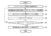
図10は、設定禁止状態から設定許可状態への切り換え処理の一例を示すフローチャートである。 FIG. 10 is a flowchart illustrating an example of a process of switching from the setting prohibited state to the setting permitted state.
ステップU1において、制御装置1は、アンロックボタン16を具備する画面を表示する。
In step U1, the
ステップU2において、制御装置1は、客先責任者又は客先作業者によるアンロックボタン16の押圧操作を受ける。
In step U2, the
ステップU3において、制御装置1は、上記図4に示すウィンドウ32を開き、「ID・パスワードが正しいか?」と表示する。
In step U3, the
ステップU4において、制御装置1は、客先責任者又は客先作業者からIDとパスワードを入力し、確定ボタン33の押圧操作を受ける。
In step U4, the
ステップU5において、制御装置1は、入力されたIDとパスワードと登録者記憶部に記憶されているIDとパスワードとが一致するか判断する。一致しない場合、処理はステップU1後の状態に戻る。
In step U5, the
一致する場合、ステップU6において、制御装置1は、ロックボタン15を具備する表示画面を表示し、客先責任者又は客先作業者による設定を許可する。なお、設定許可状態である旨を示すデータは、内部バックアップデータとして電源のオフ又はオンに関係なく登録者記憶部5aに記憶される。
If they match, in step U6, the
制御装置1の設定部5eは、成形条件の設定値が変更された場合に、変更後の現設定値、変更前の前設定値、設定者のIDを関係付けた設定履歴データを成形条件記憶部6に記憶する。そして、履歴表示部5fは、設定履歴データを画面制御部13に出力する。画面制御部13は、設定履歴データに基づいて設定履歴画面データを作成し、画面データ記憶部14に記憶する。画面表示部7は、設定履歴画面データに基づいて設定履歴画面を表示する。
When the setting value of the molding condition is changed, the
図11は、設定履歴画面の一例を示す図である。 FIG. 11 is a diagram illustrating an example of the setting history screen.
設定履歴画面40の許可欄には、設定者のIDが表示される。なお、設定者のIDは、設定許可状態において設定操作を行った者のIDである。
In the permission column of the setting
以上説明したように、本実施の形態においては、例えば客先責任者又は客先作業者などの登録者のIDとパスワードとが予め登録される。そして、予め登録されているIDとパスワードと、ユーザから入力したIDとパスワードとが一致している場合に、成形条件に関する設定許可状態又は設定禁止状態の選択が可能となる。設定許可状態においては、成形条件の設定が許可され、成形条件の設定値が変更可能となる。これにより、射出成形機2の成形条件のセキュリティを強化できる。
As described above, in the present embodiment, the ID and password of a registrant such as a customer manager or a customer worker are registered in advance. When the ID and the password registered in advance and the ID and the password input by the user match, it is possible to select the setting permission state or the setting prohibition state regarding the molding condition. In the setting permission state, setting of the molding condition is permitted, and the set value of the molding condition can be changed. Thereby, the security of the molding conditions of the
なお、本実施の形態において、画面制御部13は、登録者に対して、一以上の運転条件の設定に用いられる一以上の画面を提供し、選択部5dは、登録者の操作に応じて、一以上の画面毎に、設定許可状態と設定禁止状態とのうち少なくとも一方を選択し、設定部5eは、設定許可状態が選択された画面を用いて設定される運転条件についての設定を受け付けるとしている。
In the present embodiment, the
しかしながら、選択部5dは、画面単位で設定許可状態又は設定禁止状態を選択するのではなく、一以上の運転条件に関して個別に設定許可状態又は設定禁止状態を選択できるとしてもよい。
However, the
(第2の実施の形態)
本実施の形態では、上記第1の実施の形態の変形例について説明する。
(Second embodiment)
In the present embodiment, a modification of the first embodiment will be described.
上記第1の実施の形態における登録者認識部5は、ユーザから入力されたIDとパスワードとが、予め登録されているIDとパスワードと一致するか否かで設定許可状態又は設定禁止状態を選択可能か判断する。
The
しかしながら、本実施の形態では、IDとパスワードに代えて、指紋、声紋、虹彩、人物画像、静脈パターンなどを用いて生体認証を行う。そのため、本実施の形態では、登録者認識部5は生体認証部を具備する。
However, in the present embodiment, biometric authentication is performed using a fingerprint, a voiceprint, an iris, a person image, a vein pattern, or the like instead of the ID and the password. Therefore, in the present embodiment, the
図12は、本実施の形態に係る産業機械の制御装置1における表示装置41の一例を示す正面図である。
FIG. 12 is a front view showing an example of the
表示装置41には、生体認証部が具備されている。本実施の形態では、生体認証部の例として、指紋認証部42が用いられるとする。
The
客先責任者は、予めIDと指紋データとを登録者記憶部5aに記憶する。指紋データの入力は、上記第1の実施の形態で説明したパスワードの入力に代えて、指紋認証部42に指を接触させることで行われる。
The customer manager previously stores the ID and the fingerprint data in the
指紋の登録後、制御装置1の操作において、指紋認証部42にユーザは指を接触させるのみで認識処理が行われ、ID及びパスワードの入力は必要ない。
After the registration of the fingerprint, in the operation of the
なお、指紋に代えて虹彩を用いてもよい。虹彩は、眼球表面の部分であり、指紋と同様に、人間毎に固有の模様である。したがって、虹彩を読み取って生体認証を行うことができる。 Note that an iris may be used instead of a fingerprint. The iris is a part of the surface of the eyeball, and is a unique pattern for each person, like a fingerprint. Therefore, biometric authentication can be performed by reading the iris.
さらに、指紋、虹彩に代えて静脈パターンを用いてもよい。指や手のひら等の静脈パターンを裏側から強い光を当てて表側から読み取る。読み取られた静脈パターンは人間毎に固有の模様である。したがって、静脈パターンを読み取って生体認証を行うことができる。 Further, a vein pattern may be used instead of the fingerprint and the iris. A vein pattern such as a finger or a palm is read from the front side with strong light applied from the back side. The read vein pattern is a unique pattern for each person. Therefore, biometric authentication can be performed by reading the vein pattern.
産業機械の制御は、コンピュータを用いて行われる場合がある。この場合、コンピュータが産業機械の制御装置1に相当し、コンピュータが上記各実施の形態で説明した動作を実行する。
Control of an industrial machine may be performed using a computer. In this case, the computer corresponds to the
本発明は、産業機械を制御する分野に有効である。 The present invention is effective in the field of controlling industrial machines.
1…制御装置、2…射出成形機、3,41…表示装置、4…入力設定部、5…登録者認識部、5a…登録者記憶部、5b…画面設定部、5c…判断部、5d…選択部、5e…設定部、5f…履歴表示部、6…成形条件記憶部、7…画面表示部、8…タッチパネル、9…ダイレクト画面選択部、10…入力信号制御部、11…メイン画面メモリ、12…サブ画面メモリ、13…画面制御部、14…画面データ記憶部、15…ロックボタン、16…アンロックボタン、17a…メイン画面領域、17b…サブ画面領域、18…コントローラ機能スイッチ、19…設定器、20…モニタリングデータ表示部、40…設定履歴画面、42…指紋認証部
DESCRIPTION OF
Claims (7)
ユーザが予め登録された登録者か否か判断する手段と、
前記ユーザが前記登録者であると判断された場合に、前記登録者の操作に応じて、前記産業機械の一以上の運転条件に関して個別に設定許可状態と設定禁止状態とのうちの一方を選択する手段と、
前記登録者から、前記設定許可状態が選択された運転条件についての設定を受け付ける設定手段と
を具備することを特徴とする制御装置。 In a control device for controlling industrial machinery,
Means for determining whether the user is a pre-registered registrant;
When it is determined that the user is the registrant, one of the setting permission state and the setting prohibition state is individually selected for one or more operating conditions of the industrial machine according to the operation of the registrant. Means to
A controller configured to receive, from the registrant, a setting for the operating condition in which the setting permission state is selected.
前記設定手段は、前記設定許可状態が選択された運転条件についての設定を受け付けた場合に、運転条件の設定履歴を記憶し、
前記運転条件の設定履歴を表示する手段をさらに具備することを特徴とする制御装置。 The control device according to claim 1,
The setting means stores a setting history of the operating condition when the setting for the operating condition in which the setting permission state is selected is received,
A control device further comprising means for displaying a setting history of the operating conditions.
前記登録者に対して、前記一以上の運転条件に関して個別に前記設定許可状態と前記設定禁止状態とのうち少なくとも一方を選択可能とする画面を提供する手段をさらに具備することを特徴とする制御装置。 The control device according to claim 1 or 2,
The control further comprising a means for providing a screen to the registrant that allows at least one of the setting permission state and the setting prohibition state to be individually selected for the one or more driving conditions. apparatus.
前記登録者に対して、前記一以上の運転条件の設定に用いられる一以上の画面を提供する手段をさらに具備し、
前記選択手段は、前記登録者の操作に応じて、前記一以上の画面毎に、前記設定許可状態と前記設定禁止状態とのうち少なくとも一方を選択し、
前記設定手段は、前記設定許可状態が選択された画面を用いて設定される運転条件についての設定を受け付ける
ことを特徴とする制御装置。 The control device according to claim 1 or 2,
The registrant further comprises means for providing one or more screens used for setting the one or more driving conditions,
The selecting means selects at least one of the setting permission state and the setting prohibition state for each of the one or more screens according to the operation of the registrant,
The control device, wherein the setting unit receives a setting of an operating condition set using a screen on which the setting permission state is selected.
前記判断手段は、識別コードと暗号コードとが共に一致するか否かにより、前記ユーザが前記登録者か否か判断することを特徴とする制御装置。 The control device according to any one of claims 1 to 4,
The control device according to claim 1, wherein the determination unit determines whether the user is the registrant based on whether an identification code and an encryption code match.
前記判断手段は、指紋、声紋、虹彩、人物画像、静脈パターンのうちの少なくとも一つが一致した場合に、前記ユーザが前記登録者であると判断することを特徴とする制御装置。 The control device according to any one of claims 1 to 4,
The control device according to claim 1, wherein the determination unit determines that the user is the registrant when at least one of a fingerprint, a voiceprint, an iris, a person image, and a vein pattern matches.
前記産業機械は、射出成形機、押出成形機、工作機械、ダイキャストマシン、ロボット、半導体製造装置、印刷機のいずれかであることを特徴とする制御装置。 The control device according to any one of claims 1 to 6,
The control device, wherein the industrial machine is any one of an injection molding machine, an extrusion molding machine, a machine tool, a die casting machine, a robot, a semiconductor manufacturing device, and a printing machine.
Priority Applications (2)
| Application Number | Priority Date | Filing Date | Title |
|---|---|---|---|
| JP2003335393A JP4173790B2 (en) | 2002-10-29 | 2003-09-26 | Control device |
| US10/693,910 US6931300B2 (en) | 2002-10-29 | 2003-10-28 | Control device for injection molder determining whether user of injection molder is registered |
Applications Claiming Priority (2)
| Application Number | Priority Date | Filing Date | Title |
|---|---|---|---|
| JP2002314577 | 2002-10-29 | ||
| JP2003335393A JP4173790B2 (en) | 2002-10-29 | 2003-09-26 | Control device |
Publications (2)
| Publication Number | Publication Date |
|---|---|
| JP2004167669A true JP2004167669A (en) | 2004-06-17 |
| JP4173790B2 JP4173790B2 (en) | 2008-10-29 |
Family
ID=32179126
Family Applications (1)
| Application Number | Title | Priority Date | Filing Date |
|---|---|---|---|
| JP2003335393A Expired - Fee Related JP4173790B2 (en) | 2002-10-29 | 2003-09-26 | Control device |
Country Status (2)
| Country | Link |
|---|---|
| US (1) | US6931300B2 (en) |
| JP (1) | JP4173790B2 (en) |
Cited By (11)
| Publication number | Priority date | Publication date | Assignee | Title |
|---|---|---|---|---|
| JP2006289778A (en) * | 2005-04-11 | 2006-10-26 | Toyo Mach & Metal Co Ltd | Molding machine having user management function and individual user management method of molding machine |
| JP2006288954A (en) * | 2005-04-14 | 2006-10-26 | Olympus Medical Systems Corp | Surgery system |
| JP2007055016A (en) * | 2005-08-23 | 2007-03-08 | Toyo Mach & Metal Co Ltd | Molding machine |
| WO2011010396A1 (en) | 2009-07-22 | 2011-01-27 | 株式会社牧野フライス製作所 | Remote control system for machine tool |
| JP2012183676A (en) * | 2011-03-03 | 2012-09-27 | Sumitomo Heavy Ind Ltd | Molding machine |
| WO2012153401A1 (en) * | 2011-05-11 | 2012-11-15 | 三菱電機株式会社 | Numerical control device |
| JP2015215793A (en) * | 2014-05-12 | 2015-12-03 | 株式会社名機製作所 | Molding machine |
| JP2016124076A (en) * | 2015-01-06 | 2016-07-11 | 株式会社ダイヘン | Operation reception device |
| WO2017149667A1 (en) * | 2016-03-01 | 2017-09-08 | 富士機械製造株式会社 | Machine tool management device |
| DE102017222211A1 (en) | 2016-12-19 | 2018-06-21 | Fanuc Corporation | control unit |
| WO2018163992A1 (en) * | 2017-03-06 | 2018-09-13 | キタムラ機械株式会社 | Machining center nc operating panel |
Families Citing this family (23)
| Publication number | Priority date | Publication date | Assignee | Title |
|---|---|---|---|---|
| JP2006238287A (en) * | 2005-02-28 | 2006-09-07 | Ricoh Co Ltd | Document reader and image forming apparatus |
| JP4544462B2 (en) * | 2005-02-28 | 2010-09-15 | 株式会社リコー | Document reading apparatus and image forming apparatus |
| US7218990B2 (en) * | 2005-04-14 | 2007-05-15 | Toshiba Kikai Kabushiki Kaisha | Control device for use in injection molding machine |
| JP2006289911A (en) * | 2005-04-14 | 2006-10-26 | Toshiba Mach Co Ltd | Control device of injection molding machine |
| JP4091612B2 (en) * | 2005-04-18 | 2008-05-28 | ファナック株式会社 | Display device for injection molding machine |
| US7346425B2 (en) * | 2005-04-27 | 2008-03-18 | Toshiba Kikai Kabushiki Kaisha | Control device for use in injection molding machine |
| JP4594160B2 (en) * | 2005-04-28 | 2010-12-08 | 東芝機械株式会社 | Control device for injection molding machine |
| CN1908354A (en) * | 2005-08-05 | 2007-02-07 | 鸿富锦精密工业(深圳)有限公司 | Trick lock |
| JP4711773B2 (en) * | 2005-08-09 | 2011-06-29 | 株式会社リコー | Inkjet printer and image processing apparatus |
| PL1881388T3 (en) * | 2006-07-07 | 2014-04-30 | Ansaldo Energia Spa | Industrial plant security apparatus and monitoring method of security of an industrial plant |
| CN101590686B (en) * | 2008-05-26 | 2013-08-14 | 鸿富锦精密工业(深圳)有限公司 | Setting method for valve action |
| CA2693930C (en) * | 2009-02-23 | 2016-04-19 | Panasonic Electric Works Co., Ltd. | Monitoring and control device |
| JP2010211631A (en) * | 2009-03-11 | 2010-09-24 | Toshiba Tec Corp | Information processor |
| CN101934578B (en) * | 2009-06-29 | 2015-07-15 | 鸿富锦精密工业(深圳)有限公司 | Method for unifying operation interfaces of various injection molding machines and injection molding system |
| CN101941278A (en) * | 2009-07-03 | 2011-01-12 | 鸿富锦精密工业(深圳)有限公司 | Method for setting control parameters of injection molding machine and injection molding machine |
| WO2011104125A1 (en) * | 2010-02-26 | 2011-09-01 | Oce-Technologies B.V. | Digital image reproduction apparatus and method which can prevent changes to print job settings |
| US8949970B2 (en) * | 2012-10-31 | 2015-02-03 | Rockwell Automation Technologies, Inc. | Automation system access control system and method |
| AT513664B1 (en) | 2012-11-26 | 2015-10-15 | Engel Austria Gmbh | Operating unit for an injection molding machine |
| AT513665B1 (en) * | 2012-11-26 | 2016-01-15 | Engel Austria Gmbh | Operating unit for an injection molding machine |
| JP2016049578A (en) * | 2014-08-29 | 2016-04-11 | ファナック株式会社 | Wire cut electric discharge machine having management function of machining information |
| JP6342925B2 (en) * | 2016-02-08 | 2018-06-13 | ファナック株式会社 | Injection molding cell and injection molding cell management system |
| EP3401747A1 (en) * | 2017-05-10 | 2018-11-14 | Siemens Aktiengesellschaft | Method for operating a numerical controlled machine tool and part programme for same |
| JP7326178B2 (en) * | 2020-01-31 | 2023-08-15 | 住友重機械工業株式会社 | Injection molding machine |
Citations (5)
| Publication number | Priority date | Publication date | Assignee | Title |
|---|---|---|---|---|
| JPS6139130A (en) * | 1984-07-31 | 1986-02-25 | Fanuc Ltd | Password system |
| JPH05197409A (en) * | 1992-01-22 | 1993-08-06 | Okuma Mach Works Ltd | Numerical controller |
| JPH05216502A (en) * | 1992-02-05 | 1993-08-27 | Komatsu Ltd | Display switching device |
| JPH08328829A (en) * | 1995-06-01 | 1996-12-13 | Mitsubishi Electric Corp | Parameter change history managing system |
| JP2001145947A (en) * | 1999-11-19 | 2001-05-29 | Toshiba Mach Co Ltd | Display device of injection molding machine |
Family Cites Families (7)
| Publication number | Priority date | Publication date | Assignee | Title |
|---|---|---|---|---|
| JP3281080B2 (en) * | 1992-03-13 | 2002-05-13 | 株式会社リコー | Copier management system and facsimile machine |
| US6718378B1 (en) * | 1999-04-30 | 2004-04-06 | Canon Kabushiki Kaisha | Device management information processing apparatus method and storage medium |
| JP3619985B2 (en) * | 1999-08-23 | 2005-02-16 | 株式会社名機製作所 | Voice input device of injection molding machine and control method thereof |
| JP2001277163A (en) * | 2000-04-03 | 2001-10-09 | Sony Corp | Device and method for controlling robot |
| JP3829667B2 (en) * | 2001-08-21 | 2006-10-04 | コニカミノルタホールディングス株式会社 | Image processing apparatus, image processing method, program for executing image processing method, and storage medium storing program |
| JP2003078518A (en) * | 2001-09-03 | 2003-03-14 | Fuji Xerox Co Ltd | Encrypting/decoding system, encrypting device, decoding device and method for the same |
| US20030074590A1 (en) * | 2001-10-12 | 2003-04-17 | Fogle Steven L. | Computer system with improved entry into powersave and lock modes and method of use therefor |
-
2003
- 2003-09-26 JP JP2003335393A patent/JP4173790B2/en not_active Expired - Fee Related
- 2003-10-28 US US10/693,910 patent/US6931300B2/en not_active Expired - Lifetime
Patent Citations (5)
| Publication number | Priority date | Publication date | Assignee | Title |
|---|---|---|---|---|
| JPS6139130A (en) * | 1984-07-31 | 1986-02-25 | Fanuc Ltd | Password system |
| JPH05197409A (en) * | 1992-01-22 | 1993-08-06 | Okuma Mach Works Ltd | Numerical controller |
| JPH05216502A (en) * | 1992-02-05 | 1993-08-27 | Komatsu Ltd | Display switching device |
| JPH08328829A (en) * | 1995-06-01 | 1996-12-13 | Mitsubishi Electric Corp | Parameter change history managing system |
| JP2001145947A (en) * | 1999-11-19 | 2001-05-29 | Toshiba Mach Co Ltd | Display device of injection molding machine |
Cited By (18)
| Publication number | Priority date | Publication date | Assignee | Title |
|---|---|---|---|---|
| JP2006289778A (en) * | 2005-04-11 | 2006-10-26 | Toyo Mach & Metal Co Ltd | Molding machine having user management function and individual user management method of molding machine |
| JP2006288954A (en) * | 2005-04-14 | 2006-10-26 | Olympus Medical Systems Corp | Surgery system |
| JP2007055016A (en) * | 2005-08-23 | 2007-03-08 | Toyo Mach & Metal Co Ltd | Molding machine |
| WO2011010396A1 (en) | 2009-07-22 | 2011-01-27 | 株式会社牧野フライス製作所 | Remote control system for machine tool |
| JP2012183676A (en) * | 2011-03-03 | 2012-09-27 | Sumitomo Heavy Ind Ltd | Molding machine |
| WO2012153401A1 (en) * | 2011-05-11 | 2012-11-15 | 三菱電機株式会社 | Numerical control device |
| JP2015215793A (en) * | 2014-05-12 | 2015-12-03 | 株式会社名機製作所 | Molding machine |
| JP2016124076A (en) * | 2015-01-06 | 2016-07-11 | 株式会社ダイヘン | Operation reception device |
| WO2017149667A1 (en) * | 2016-03-01 | 2017-09-08 | 富士機械製造株式会社 | Machine tool management device |
| JPWO2017149667A1 (en) * | 2016-03-01 | 2018-12-20 | 株式会社Fuji | Machine tool management device |
| DE102017222211A1 (en) | 2016-12-19 | 2018-06-21 | Fanuc Corporation | control unit |
| CN108205281A (en) * | 2016-12-19 | 2018-06-26 | 发那科株式会社 | Control device |
| JP2018099744A (en) * | 2016-12-19 | 2018-06-28 | ファナック株式会社 | Controller |
| US10571882B2 (en) | 2016-12-19 | 2020-02-25 | Fanuc Corporation | Controller |
| CN108205281B (en) * | 2016-12-19 | 2020-06-23 | 发那科株式会社 | Control device |
| WO2018163992A1 (en) * | 2017-03-06 | 2018-09-13 | キタムラ機械株式会社 | Machining center nc operating panel |
| JP2018147236A (en) * | 2017-03-06 | 2018-09-20 | キタムラ機械株式会社 | Machining center nc control panel |
| US11231695B2 (en) | 2017-03-06 | 2022-01-25 | Kitamura Machinery Co., Ltd. | Machining center NC operating panel |
Also Published As
| Publication number | Publication date |
|---|---|
| US6931300B2 (en) | 2005-08-16 |
| JP4173790B2 (en) | 2008-10-29 |
| US20040088066A1 (en) | 2004-05-06 |
Similar Documents
| Publication | Publication Date | Title |
|---|---|---|
| JP4173790B2 (en) | Control device | |
| JP3880651B2 (en) | Method and apparatus for displaying setting screen in touch input display device using touch panel | |
| JP4865826B2 (en) | Authentication apparatus, authentication method, authentication program, and computer-readable recording medium recording the same | |
| AU2015219884B2 (en) | Electric lock control device | |
| JP5380053B2 (en) | Locker device and control method thereof | |
| JP6713688B2 (en) | Machining center NC operation panel | |
| JP4878770B2 (en) | Molding machine having user management function and individual user management method of molding machine | |
| JP2007148801A (en) | Fingerprint collation device | |
| JP2010126913A (en) | Electronic lock device and locker equipment | |
| EP0126286B1 (en) | Electronic cash register | |
| WO2017179730A1 (en) | Display operation device and molding machine | |
| JP2008077159A (en) | Input device and electronic apparatus having the same | |
| JP6057475B2 (en) | Molding machine | |
| JP5291911B2 (en) | Measuring system | |
| US20080134318A1 (en) | Authentication device, authentication method, authentication program and computer-readable recording medium storing the same | |
| JP2004243472A (en) | Operating device and industrial robot | |
| JP2001125602A (en) | Supervisory controller | |
| JP2000029837A (en) | Individual authentication method, user authentication device and recording medium | |
| JP2735711B2 (en) | Control method for enabling / disabling setting operation in injection molding machine | |
| JP2578280B2 (en) | Molding machine controller | |
| JPH05334334A (en) | Password number input device | |
| JP2004155074A (en) | Display method for operation switch of injection molding machine | |
| JP2010126915A (en) | Electronic lock device, locker equipment, and method for controlling the electronic lock device | |
| JP2005258838A (en) | Ten key operation display device | |
| JP2009015501A (en) | Personal identification device |
Legal Events
| Date | Code | Title | Description |
|---|---|---|---|
| A621 | Written request for application examination |
Free format text: JAPANESE INTERMEDIATE CODE: A621 Effective date: 20060228 |
|
| A977 | Report on retrieval |
Free format text: JAPANESE INTERMEDIATE CODE: A971007 Effective date: 20070720 |
|
| A131 | Notification of reasons for refusal |
Free format text: JAPANESE INTERMEDIATE CODE: A131 Effective date: 20080205 |
|
| A521 | Request for written amendment filed |
Free format text: JAPANESE INTERMEDIATE CODE: A523 Effective date: 20080404 |
|
| TRDD | Decision of grant or rejection written | ||
| A01 | Written decision to grant a patent or to grant a registration (utility model) |
Free format text: JAPANESE INTERMEDIATE CODE: A01 Effective date: 20080805 |
|
| A01 | Written decision to grant a patent or to grant a registration (utility model) |
Free format text: JAPANESE INTERMEDIATE CODE: A01 |
|
| A61 | First payment of annual fees (during grant procedure) |
Free format text: JAPANESE INTERMEDIATE CODE: A61 Effective date: 20080814 |
|
| R150 | Certificate of patent or registration of utility model |
Ref document number: 4173790 Country of ref document: JP Free format text: JAPANESE INTERMEDIATE CODE: R150 |
|
| FPAY | Renewal fee payment (event date is renewal date of database) |
Free format text: PAYMENT UNTIL: 20110822 Year of fee payment: 3 |
|
| FPAY | Renewal fee payment (event date is renewal date of database) |
Free format text: PAYMENT UNTIL: 20120822 Year of fee payment: 4 |
|
| FPAY | Renewal fee payment (event date is renewal date of database) |
Free format text: PAYMENT UNTIL: 20120822 Year of fee payment: 4 |
|
| FPAY | Renewal fee payment (event date is renewal date of database) |
Free format text: PAYMENT UNTIL: 20130822 Year of fee payment: 5 |
|
| S533 | Written request for registration of change of name |
Free format text: JAPANESE INTERMEDIATE CODE: R313533 |
|
| R350 | Written notification of registration of transfer |
Free format text: JAPANESE INTERMEDIATE CODE: R350 |
|
| LAPS | Cancellation because of no payment of annual fees |