EP4442438A1 - Vacuum packaging machine - Google Patents
Vacuum packaging machine Download PDFInfo
- Publication number
- EP4442438A1 EP4442438A1 EP24167334.2A EP24167334A EP4442438A1 EP 4442438 A1 EP4442438 A1 EP 4442438A1 EP 24167334 A EP24167334 A EP 24167334A EP 4442438 A1 EP4442438 A1 EP 4442438A1
- Authority
- EP
- European Patent Office
- Prior art keywords
- heat
- stem
- electrically conducting
- sealing bar
- packaging machine
- Prior art date
- Legal status (The legal status is an assumption and is not a legal conclusion. Google has not performed a legal analysis and makes no representation as to the accuracy of the status listed.)
- Pending
Links
- 238000009461 vacuum packaging Methods 0.000 title claims abstract description 31
- 238000007789 sealing Methods 0.000 claims abstract description 116
- 238000004806 packaging method and process Methods 0.000 claims abstract description 27
- 235000013305 food Nutrition 0.000 claims abstract description 9
- 230000006835 compression Effects 0.000 claims abstract description 3
- 238000007906 compression Methods 0.000 claims abstract description 3
- 238000003780 insertion Methods 0.000 claims description 2
- 230000037431 insertion Effects 0.000 claims description 2
- 239000000463 material Substances 0.000 description 6
- 239000004020 conductor Substances 0.000 description 4
- 238000010276 construction Methods 0.000 description 3
- 238000010438 heat treatment Methods 0.000 description 3
- 230000000670 limiting effect Effects 0.000 description 2
- 230000004913 activation Effects 0.000 description 1
- 230000001580 bacterial effect Effects 0.000 description 1
- 230000005540 biological transmission Effects 0.000 description 1
- 230000002860 competitive effect Effects 0.000 description 1
- 230000001419 dependent effect Effects 0.000 description 1
- 238000006073 displacement reaction Methods 0.000 description 1
- 230000005611 electricity Effects 0.000 description 1
- 238000009413 insulation Methods 0.000 description 1
- 238000005259 measurement Methods 0.000 description 1
- 238000012986 modification Methods 0.000 description 1
- 230000004048 modification Effects 0.000 description 1
- 239000002245 particle Substances 0.000 description 1
- 230000002093 peripheral effect Effects 0.000 description 1
- 229920001296 polysiloxane Polymers 0.000 description 1
- 230000035755 proliferation Effects 0.000 description 1
- 238000003466 welding Methods 0.000 description 1
Images


Classifications
-
- B—PERFORMING OPERATIONS; TRANSPORTING
- B29—WORKING OF PLASTICS; WORKING OF SUBSTANCES IN A PLASTIC STATE IN GENERAL
- B29C—SHAPING OR JOINING OF PLASTICS; SHAPING OF MATERIAL IN A PLASTIC STATE, NOT OTHERWISE PROVIDED FOR; AFTER-TREATMENT OF THE SHAPED PRODUCTS, e.g. REPAIRING
- B29C65/00—Joining or sealing of preformed parts, e.g. welding of plastics materials; Apparatus therefor
- B29C65/02—Joining or sealing of preformed parts, e.g. welding of plastics materials; Apparatus therefor by heating, with or without pressure
- B29C65/18—Joining or sealing of preformed parts, e.g. welding of plastics materials; Apparatus therefor by heating, with or without pressure using heated tools
- B29C65/22—Heated wire resistive ribbon, resistive band or resistive strip
- B29C65/228—Heated wire resistive ribbon, resistive band or resistive strip characterised by the means for electrically connecting the ends of said heated wire, resistive ribbon, resistive band or resistive strip
-
- B—PERFORMING OPERATIONS; TRANSPORTING
- B29—WORKING OF PLASTICS; WORKING OF SUBSTANCES IN A PLASTIC STATE IN GENERAL
- B29C—SHAPING OR JOINING OF PLASTICS; SHAPING OF MATERIAL IN A PLASTIC STATE, NOT OTHERWISE PROVIDED FOR; AFTER-TREATMENT OF THE SHAPED PRODUCTS, e.g. REPAIRING
- B29C65/00—Joining or sealing of preformed parts, e.g. welding of plastics materials; Apparatus therefor
- B29C65/02—Joining or sealing of preformed parts, e.g. welding of plastics materials; Apparatus therefor by heating, with or without pressure
- B29C65/18—Joining or sealing of preformed parts, e.g. welding of plastics materials; Apparatus therefor by heating, with or without pressure using heated tools
- B29C65/22—Heated wire resistive ribbon, resistive band or resistive strip
- B29C65/221—Heated wire resistive ribbon, resistive band or resistive strip characterised by the type of heated wire, resistive ribbon, band or strip
- B29C65/222—Heated wire resistive ribbon, resistive band or resistive strip characterised by the type of heated wire, resistive ribbon, band or strip comprising at least a single heated wire
-
- B—PERFORMING OPERATIONS; TRANSPORTING
- B29—WORKING OF PLASTICS; WORKING OF SUBSTANCES IN A PLASTIC STATE IN GENERAL
- B29C—SHAPING OR JOINING OF PLASTICS; SHAPING OF MATERIAL IN A PLASTIC STATE, NOT OTHERWISE PROVIDED FOR; AFTER-TREATMENT OF THE SHAPED PRODUCTS, e.g. REPAIRING
- B29C65/00—Joining or sealing of preformed parts, e.g. welding of plastics materials; Apparatus therefor
- B29C65/02—Joining or sealing of preformed parts, e.g. welding of plastics materials; Apparatus therefor by heating, with or without pressure
- B29C65/18—Joining or sealing of preformed parts, e.g. welding of plastics materials; Apparatus therefor by heating, with or without pressure using heated tools
- B29C65/22—Heated wire resistive ribbon, resistive band or resistive strip
- B29C65/221—Heated wire resistive ribbon, resistive band or resistive strip characterised by the type of heated wire, resistive ribbon, band or strip
- B29C65/224—Heated wire resistive ribbon, resistive band or resistive strip characterised by the type of heated wire, resistive ribbon, band or strip being a resistive ribbon, a resistive band or a resistive strip
-
- B—PERFORMING OPERATIONS; TRANSPORTING
- B29—WORKING OF PLASTICS; WORKING OF SUBSTANCES IN A PLASTIC STATE IN GENERAL
- B29C—SHAPING OR JOINING OF PLASTICS; SHAPING OF MATERIAL IN A PLASTIC STATE, NOT OTHERWISE PROVIDED FOR; AFTER-TREATMENT OF THE SHAPED PRODUCTS, e.g. REPAIRING
- B29C65/00—Joining or sealing of preformed parts, e.g. welding of plastics materials; Apparatus therefor
- B29C65/74—Joining or sealing of preformed parts, e.g. welding of plastics materials; Apparatus therefor by welding and severing, or by joining and severing, the severing being performed in the area to be joined, next to the area to be joined, in the joint area or next to the joint area
- B29C65/741—Joining or sealing of preformed parts, e.g. welding of plastics materials; Apparatus therefor by welding and severing, or by joining and severing, the severing being performed in the area to be joined, next to the area to be joined, in the joint area or next to the joint area characterised by the relationships between the joining step and the severing step
- B29C65/7411—Joining or sealing of preformed parts, e.g. welding of plastics materials; Apparatus therefor by welding and severing, or by joining and severing, the severing being performed in the area to be joined, next to the area to be joined, in the joint area or next to the joint area characterised by the relationships between the joining step and the severing step characterised by the temperature relationship between the joining step and the severing step
- B29C65/7412—Joining or sealing of preformed parts, e.g. welding of plastics materials; Apparatus therefor by welding and severing, or by joining and severing, the severing being performed in the area to be joined, next to the area to be joined, in the joint area or next to the joint area characterised by the relationships between the joining step and the severing step characterised by the temperature relationship between the joining step and the severing step the joining step and the severing step being performed at different temperatures
-
- B—PERFORMING OPERATIONS; TRANSPORTING
- B29—WORKING OF PLASTICS; WORKING OF SUBSTANCES IN A PLASTIC STATE IN GENERAL
- B29C—SHAPING OR JOINING OF PLASTICS; SHAPING OF MATERIAL IN A PLASTIC STATE, NOT OTHERWISE PROVIDED FOR; AFTER-TREATMENT OF THE SHAPED PRODUCTS, e.g. REPAIRING
- B29C65/00—Joining or sealing of preformed parts, e.g. welding of plastics materials; Apparatus therefor
- B29C65/74—Joining or sealing of preformed parts, e.g. welding of plastics materials; Apparatus therefor by welding and severing, or by joining and severing, the severing being performed in the area to be joined, next to the area to be joined, in the joint area or next to the joint area
- B29C65/745—Joining or sealing of preformed parts, e.g. welding of plastics materials; Apparatus therefor by welding and severing, or by joining and severing, the severing being performed in the area to be joined, next to the area to be joined, in the joint area or next to the joint area using a single unit having both a severing tool and a welding tool
- B29C65/7453—Joining or sealing of preformed parts, e.g. welding of plastics materials; Apparatus therefor by welding and severing, or by joining and severing, the severing being performed in the area to be joined, next to the area to be joined, in the joint area or next to the joint area using a single unit having both a severing tool and a welding tool the severing tool being a wire
-
- B—PERFORMING OPERATIONS; TRANSPORTING
- B29—WORKING OF PLASTICS; WORKING OF SUBSTANCES IN A PLASTIC STATE IN GENERAL
- B29C—SHAPING OR JOINING OF PLASTICS; SHAPING OF MATERIAL IN A PLASTIC STATE, NOT OTHERWISE PROVIDED FOR; AFTER-TREATMENT OF THE SHAPED PRODUCTS, e.g. REPAIRING
- B29C66/00—General aspects of processes or apparatus for joining preformed parts
- B29C66/01—General aspects dealing with the joint area or with the area to be joined
- B29C66/05—Particular design of joint configurations
- B29C66/10—Particular design of joint configurations particular design of the joint cross-sections
- B29C66/11—Joint cross-sections comprising a single joint-segment, i.e. one of the parts to be joined comprising a single joint-segment in the joint cross-section
- B29C66/112—Single lapped joints
- B29C66/1122—Single lap to lap joints, i.e. overlap joints
-
- B—PERFORMING OPERATIONS; TRANSPORTING
- B29—WORKING OF PLASTICS; WORKING OF SUBSTANCES IN A PLASTIC STATE IN GENERAL
- B29C—SHAPING OR JOINING OF PLASTICS; SHAPING OF MATERIAL IN A PLASTIC STATE, NOT OTHERWISE PROVIDED FOR; AFTER-TREATMENT OF THE SHAPED PRODUCTS, e.g. REPAIRING
- B29C66/00—General aspects of processes or apparatus for joining preformed parts
- B29C66/01—General aspects dealing with the joint area or with the area to be joined
- B29C66/05—Particular design of joint configurations
- B29C66/20—Particular design of joint configurations particular design of the joint lines, e.g. of the weld lines
- B29C66/23—Particular design of joint configurations particular design of the joint lines, e.g. of the weld lines said joint lines being multiple and parallel or being in the form of tessellations
- B29C66/232—Particular design of joint configurations particular design of the joint lines, e.g. of the weld lines said joint lines being multiple and parallel or being in the form of tessellations said joint lines being multiple and parallel, i.e. the joint being formed by several parallel joint lines
-
- B—PERFORMING OPERATIONS; TRANSPORTING
- B29—WORKING OF PLASTICS; WORKING OF SUBSTANCES IN A PLASTIC STATE IN GENERAL
- B29C—SHAPING OR JOINING OF PLASTICS; SHAPING OF MATERIAL IN A PLASTIC STATE, NOT OTHERWISE PROVIDED FOR; AFTER-TREATMENT OF THE SHAPED PRODUCTS, e.g. REPAIRING
- B29C66/00—General aspects of processes or apparatus for joining preformed parts
- B29C66/40—General aspects of joining substantially flat articles, e.g. plates, sheets or web-like materials; Making flat seams in tubular or hollow articles; Joining single elements to substantially flat surfaces
- B29C66/41—Joining substantially flat articles ; Making flat seams in tubular or hollow articles
- B29C66/43—Joining a relatively small portion of the surface of said articles
- B29C66/431—Joining the articles to themselves
- B29C66/4312—Joining the articles to themselves for making flat seams in tubular or hollow articles, e.g. transversal seams
- B29C66/43121—Closing the ends of tubular or hollow single articles, e.g. closing the ends of bags
-
- B—PERFORMING OPERATIONS; TRANSPORTING
- B29—WORKING OF PLASTICS; WORKING OF SUBSTANCES IN A PLASTIC STATE IN GENERAL
- B29C—SHAPING OR JOINING OF PLASTICS; SHAPING OF MATERIAL IN A PLASTIC STATE, NOT OTHERWISE PROVIDED FOR; AFTER-TREATMENT OF THE SHAPED PRODUCTS, e.g. REPAIRING
- B29C66/00—General aspects of processes or apparatus for joining preformed parts
- B29C66/70—General aspects of processes or apparatus for joining preformed parts characterised by the composition, physical properties or the structure of the material of the parts to be joined; Joining with non-plastics material
- B29C66/73—General aspects of processes or apparatus for joining preformed parts characterised by the composition, physical properties or the structure of the material of the parts to be joined; Joining with non-plastics material characterised by the intensive physical properties of the material of the parts to be joined, by the optical properties of the material of the parts to be joined, by the extensive physical properties of the parts to be joined, by the state of the material of the parts to be joined or by the material of the parts to be joined being a thermoplastic or a thermoset
- B29C66/739—General aspects of processes or apparatus for joining preformed parts characterised by the composition, physical properties or the structure of the material of the parts to be joined; Joining with non-plastics material characterised by the intensive physical properties of the material of the parts to be joined, by the optical properties of the material of the parts to be joined, by the extensive physical properties of the parts to be joined, by the state of the material of the parts to be joined or by the material of the parts to be joined being a thermoplastic or a thermoset characterised by the material of the parts to be joined being a thermoplastic or a thermoset
- B29C66/7392—General aspects of processes or apparatus for joining preformed parts characterised by the composition, physical properties or the structure of the material of the parts to be joined; Joining with non-plastics material characterised by the intensive physical properties of the material of the parts to be joined, by the optical properties of the material of the parts to be joined, by the extensive physical properties of the parts to be joined, by the state of the material of the parts to be joined or by the material of the parts to be joined being a thermoplastic or a thermoset characterised by the material of the parts to be joined being a thermoplastic or a thermoset characterised by the material of at least one of the parts being a thermoplastic
- B29C66/73921—General aspects of processes or apparatus for joining preformed parts characterised by the composition, physical properties or the structure of the material of the parts to be joined; Joining with non-plastics material characterised by the intensive physical properties of the material of the parts to be joined, by the optical properties of the material of the parts to be joined, by the extensive physical properties of the parts to be joined, by the state of the material of the parts to be joined or by the material of the parts to be joined being a thermoplastic or a thermoset characterised by the material of the parts to be joined being a thermoplastic or a thermoset characterised by the material of at least one of the parts being a thermoplastic characterised by the materials of both parts being thermoplastics
-
- B—PERFORMING OPERATIONS; TRANSPORTING
- B29—WORKING OF PLASTICS; WORKING OF SUBSTANCES IN A PLASTIC STATE IN GENERAL
- B29C—SHAPING OR JOINING OF PLASTICS; SHAPING OF MATERIAL IN A PLASTIC STATE, NOT OTHERWISE PROVIDED FOR; AFTER-TREATMENT OF THE SHAPED PRODUCTS, e.g. REPAIRING
- B29C66/00—General aspects of processes or apparatus for joining preformed parts
- B29C66/80—General aspects of machine operations or constructions and parts thereof
- B29C66/82—Pressure application arrangements, e.g. transmission or actuating mechanisms for joining tools or clamps
- B29C66/824—Actuating mechanisms
- B29C66/8242—Pneumatic or hydraulic drives
-
- B—PERFORMING OPERATIONS; TRANSPORTING
- B29—WORKING OF PLASTICS; WORKING OF SUBSTANCES IN A PLASTIC STATE IN GENERAL
- B29C—SHAPING OR JOINING OF PLASTICS; SHAPING OF MATERIAL IN A PLASTIC STATE, NOT OTHERWISE PROVIDED FOR; AFTER-TREATMENT OF THE SHAPED PRODUCTS, e.g. REPAIRING
- B29C66/00—General aspects of processes or apparatus for joining preformed parts
- B29C66/80—General aspects of machine operations or constructions and parts thereof
- B29C66/83—General aspects of machine operations or constructions and parts thereof characterised by the movement of the joining or pressing tools
- B29C66/832—Reciprocating joining or pressing tools
- B29C66/8322—Joining or pressing tools reciprocating along one axis
-
- B—PERFORMING OPERATIONS; TRANSPORTING
- B29—WORKING OF PLASTICS; WORKING OF SUBSTANCES IN A PLASTIC STATE IN GENERAL
- B29C—SHAPING OR JOINING OF PLASTICS; SHAPING OF MATERIAL IN A PLASTIC STATE, NOT OTHERWISE PROVIDED FOR; AFTER-TREATMENT OF THE SHAPED PRODUCTS, e.g. REPAIRING
- B29C66/00—General aspects of processes or apparatus for joining preformed parts
- B29C66/80—General aspects of machine operations or constructions and parts thereof
- B29C66/84—Specific machine types or machines suitable for specific applications
- B29C66/849—Packaging machines
-
- B—PERFORMING OPERATIONS; TRANSPORTING
- B29—WORKING OF PLASTICS; WORKING OF SUBSTANCES IN A PLASTIC STATE IN GENERAL
- B29C—SHAPING OR JOINING OF PLASTICS; SHAPING OF MATERIAL IN A PLASTIC STATE, NOT OTHERWISE PROVIDED FOR; AFTER-TREATMENT OF THE SHAPED PRODUCTS, e.g. REPAIRING
- B29C66/00—General aspects of processes or apparatus for joining preformed parts
- B29C66/90—Measuring or controlling the joining process
- B29C66/91—Measuring or controlling the joining process by measuring or controlling the temperature, the heat or the thermal flux
- B29C66/914—Measuring or controlling the joining process by measuring or controlling the temperature, the heat or the thermal flux by controlling or regulating the temperature, the heat or the thermal flux
- B29C66/9161—Measuring or controlling the joining process by measuring or controlling the temperature, the heat or the thermal flux by controlling or regulating the temperature, the heat or the thermal flux by controlling or regulating the heat or the thermal flux, i.e. the heat flux
- B29C66/91641—Measuring or controlling the joining process by measuring or controlling the temperature, the heat or the thermal flux by controlling or regulating the temperature, the heat or the thermal flux by controlling or regulating the heat or the thermal flux, i.e. the heat flux the heat or the thermal flux being non-constant over time
-
- B—PERFORMING OPERATIONS; TRANSPORTING
- B29—WORKING OF PLASTICS; WORKING OF SUBSTANCES IN A PLASTIC STATE IN GENERAL
- B29C—SHAPING OR JOINING OF PLASTICS; SHAPING OF MATERIAL IN A PLASTIC STATE, NOT OTHERWISE PROVIDED FOR; AFTER-TREATMENT OF THE SHAPED PRODUCTS, e.g. REPAIRING
- B29C66/00—General aspects of processes or apparatus for joining preformed parts
- B29C66/90—Measuring or controlling the joining process
- B29C66/91—Measuring or controlling the joining process by measuring or controlling the temperature, the heat or the thermal flux
- B29C66/914—Measuring or controlling the joining process by measuring or controlling the temperature, the heat or the thermal flux by controlling or regulating the temperature, the heat or the thermal flux
- B29C66/9161—Measuring or controlling the joining process by measuring or controlling the temperature, the heat or the thermal flux by controlling or regulating the temperature, the heat or the thermal flux by controlling or regulating the heat or the thermal flux, i.e. the heat flux
- B29C66/91651—Measuring or controlling the joining process by measuring or controlling the temperature, the heat or the thermal flux by controlling or regulating the temperature, the heat or the thermal flux by controlling or regulating the heat or the thermal flux, i.e. the heat flux by controlling or regulating the heat generated by Joule heating or induction heating
- B29C66/91653—Measuring or controlling the joining process by measuring or controlling the temperature, the heat or the thermal flux by controlling or regulating the temperature, the heat or the thermal flux by controlling or regulating the heat or the thermal flux, i.e. the heat flux by controlling or regulating the heat generated by Joule heating or induction heating by controlling or regulating the voltage, i.e. the electric potential difference or electric tension
-
- B—PERFORMING OPERATIONS; TRANSPORTING
- B29—WORKING OF PLASTICS; WORKING OF SUBSTANCES IN A PLASTIC STATE IN GENERAL
- B29C—SHAPING OR JOINING OF PLASTICS; SHAPING OF MATERIAL IN A PLASTIC STATE, NOT OTHERWISE PROVIDED FOR; AFTER-TREATMENT OF THE SHAPED PRODUCTS, e.g. REPAIRING
- B29C66/00—General aspects of processes or apparatus for joining preformed parts
- B29C66/90—Measuring or controlling the joining process
- B29C66/91—Measuring or controlling the joining process by measuring or controlling the temperature, the heat or the thermal flux
- B29C66/914—Measuring or controlling the joining process by measuring or controlling the temperature, the heat or the thermal flux by controlling or regulating the temperature, the heat or the thermal flux
- B29C66/9161—Measuring or controlling the joining process by measuring or controlling the temperature, the heat or the thermal flux by controlling or regulating the temperature, the heat or the thermal flux by controlling or regulating the heat or the thermal flux, i.e. the heat flux
- B29C66/91651—Measuring or controlling the joining process by measuring or controlling the temperature, the heat or the thermal flux by controlling or regulating the temperature, the heat or the thermal flux by controlling or regulating the heat or the thermal flux, i.e. the heat flux by controlling or regulating the heat generated by Joule heating or induction heating
- B29C66/91655—Measuring or controlling the joining process by measuring or controlling the temperature, the heat or the thermal flux by controlling or regulating the temperature, the heat or the thermal flux by controlling or regulating the heat or the thermal flux, i.e. the heat flux by controlling or regulating the heat generated by Joule heating or induction heating by controlling or regulating the current intensity
-
- B—PERFORMING OPERATIONS; TRANSPORTING
- B65—CONVEYING; PACKING; STORING; HANDLING THIN OR FILAMENTARY MATERIAL
- B65B—MACHINES, APPARATUS OR DEVICES FOR, OR METHODS OF, PACKAGING ARTICLES OR MATERIALS; UNPACKING
- B65B31/00—Packaging articles or materials under special atmospheric or gaseous conditions; Adding propellants to aerosol containers
- B65B31/02—Filling, closing, or filling and closing, containers or wrappers in chambers maintained under vacuum or superatmospheric pressure or containing a special atmosphere, e.g. of inert gas
- B65B31/024—Filling, closing, or filling and closing, containers or wrappers in chambers maintained under vacuum or superatmospheric pressure or containing a special atmosphere, e.g. of inert gas specially adapted for wrappers or bags
-
- B—PERFORMING OPERATIONS; TRANSPORTING
- B65—CONVEYING; PACKING; STORING; HANDLING THIN OR FILAMENTARY MATERIAL
- B65B—MACHINES, APPARATUS OR DEVICES FOR, OR METHODS OF, PACKAGING ARTICLES OR MATERIALS; UNPACKING
- B65B31/00—Packaging articles or materials under special atmospheric or gaseous conditions; Adding propellants to aerosol containers
- B65B31/04—Evacuating, pressurising or gasifying filled containers or wrappers by means of nozzles through which air or other gas, e.g. an inert gas, is withdrawn or supplied
- B65B31/046—Evacuating, pressurising or gasifying filled containers or wrappers by means of nozzles through which air or other gas, e.g. an inert gas, is withdrawn or supplied the nozzles co-operating, or being combined, with a device for opening or closing the container or wrapper
- B65B31/048—Evacuating, pressurising or gasifying filled containers or wrappers by means of nozzles through which air or other gas, e.g. an inert gas, is withdrawn or supplied the nozzles co-operating, or being combined, with a device for opening or closing the container or wrapper specially adapted for wrappers or bags
-
- B—PERFORMING OPERATIONS; TRANSPORTING
- B65—CONVEYING; PACKING; STORING; HANDLING THIN OR FILAMENTARY MATERIAL
- B65B—MACHINES, APPARATUS OR DEVICES FOR, OR METHODS OF, PACKAGING ARTICLES OR MATERIALS; UNPACKING
- B65B51/00—Devices for, or methods of, sealing or securing package folds or closures; Devices for gathering or twisting wrappers, or necks of bags
- B65B51/10—Applying or generating heat or pressure or combinations thereof
- B65B51/14—Applying or generating heat or pressure or combinations thereof by reciprocating or oscillating members
- B65B51/146—Closing bags
-
- B—PERFORMING OPERATIONS; TRANSPORTING
- B65—CONVEYING; PACKING; STORING; HANDLING THIN OR FILAMENTARY MATERIAL
- B65B—MACHINES, APPARATUS OR DEVICES FOR, OR METHODS OF, PACKAGING ARTICLES OR MATERIALS; UNPACKING
- B65B61/00—Auxiliary devices, not otherwise provided for, for operating on sheets, blanks, webs, binding material, containers or packages
- B65B61/04—Auxiliary devices, not otherwise provided for, for operating on sheets, blanks, webs, binding material, containers or packages for severing webs, or for separating joined packages
- B65B61/06—Auxiliary devices, not otherwise provided for, for operating on sheets, blanks, webs, binding material, containers or packages for severing webs, or for separating joined packages by cutting
- B65B61/10—Auxiliary devices, not otherwise provided for, for operating on sheets, blanks, webs, binding material, containers or packages for severing webs, or for separating joined packages by cutting using heated wires or cutters
-
- B—PERFORMING OPERATIONS; TRANSPORTING
- B29—WORKING OF PLASTICS; WORKING OF SUBSTANCES IN A PLASTIC STATE IN GENERAL
- B29C—SHAPING OR JOINING OF PLASTICS; SHAPING OF MATERIAL IN A PLASTIC STATE, NOT OTHERWISE PROVIDED FOR; AFTER-TREATMENT OF THE SHAPED PRODUCTS, e.g. REPAIRING
- B29C65/00—Joining or sealing of preformed parts, e.g. welding of plastics materials; Apparatus therefor
- B29C65/02—Joining or sealing of preformed parts, e.g. welding of plastics materials; Apparatus therefor by heating, with or without pressure
- B29C65/18—Joining or sealing of preformed parts, e.g. welding of plastics materials; Apparatus therefor by heating, with or without pressure using heated tools
- B29C65/22—Heated wire resistive ribbon, resistive band or resistive strip
- B29C65/221—Heated wire resistive ribbon, resistive band or resistive strip characterised by the type of heated wire, resistive ribbon, band or strip
- B29C65/222—Heated wire resistive ribbon, resistive band or resistive strip characterised by the type of heated wire, resistive ribbon, band or strip comprising at least a single heated wire
- B29C65/223—Heated wire resistive ribbon, resistive band or resistive strip characterised by the type of heated wire, resistive ribbon, band or strip comprising at least a single heated wire comprising several heated wires
-
- B—PERFORMING OPERATIONS; TRANSPORTING
- B29—WORKING OF PLASTICS; WORKING OF SUBSTANCES IN A PLASTIC STATE IN GENERAL
- B29C—SHAPING OR JOINING OF PLASTICS; SHAPING OF MATERIAL IN A PLASTIC STATE, NOT OTHERWISE PROVIDED FOR; AFTER-TREATMENT OF THE SHAPED PRODUCTS, e.g. REPAIRING
- B29C65/00—Joining or sealing of preformed parts, e.g. welding of plastics materials; Apparatus therefor
- B29C65/02—Joining or sealing of preformed parts, e.g. welding of plastics materials; Apparatus therefor by heating, with or without pressure
- B29C65/18—Joining or sealing of preformed parts, e.g. welding of plastics materials; Apparatus therefor by heating, with or without pressure using heated tools
- B29C65/22—Heated wire resistive ribbon, resistive band or resistive strip
- B29C65/229—Heated wire resistive ribbon, resistive band or resistive strip characterised by the means for tensioning said heated wire, resistive ribbon, resistive band or resistive strip
-
- B—PERFORMING OPERATIONS; TRANSPORTING
- B29—WORKING OF PLASTICS; WORKING OF SUBSTANCES IN A PLASTIC STATE IN GENERAL
- B29L—INDEXING SCHEME ASSOCIATED WITH SUBCLASS B29C, RELATING TO PARTICULAR ARTICLES
- B29L2031/00—Other particular articles
- B29L2031/712—Containers; Packaging elements or accessories, Packages
- B29L2031/7128—Bags, sacks, sachets
Definitions
- the present invention relates to a vacuum packaging machine.
- Vacuum packaging machines which make it possible to package products of various kinds and, in particular, foods, in a wrapper, such as a bag or a pouch, inside which the vacuum has been created, in order to enable an optimal conservation of the products.
- packaging machines of the "bell" type which generally have a base structure, which defines a packaging chamber or vacuum chamber, which can be closed in an upward region by a lid, hinged to the base structure and substantially bell-shaped, and which is designed to receive at least one wrapper, constituted for example by a sealable pouch, in which the food to be packaged has been placed.
- the packaging chamber is connected to vacuum generation means, constituted typically by a vacuum pump capable of creating the at least partial vacuum inside the vacuum chamber, once its lid is closed, so as to extract the air from the pouch, with the food inserted in it, placed in the packaging chamber.
- vacuum generation means constituted typically by a vacuum pump capable of creating the at least partial vacuum inside the vacuum chamber, once its lid is closed, so as to extract the air from the pouch, with the food inserted in it, placed in the packaging chamber.
- the packaging chamber means for sealing the pouch are moreover provided, which make it possible to hermetically close the pouch substantially at its inlet, once the vacuum is created inside it, by way of heat-sealing its opposite free flaps along two heat-sealing lines produced as a consequence of heating and compressing the flaps to be heat-sealed.
- the means for sealing are constituted by at least one heat-sealing or welding bar, which cooperates with an abutment element, constituted by a sealing contrast bar, directed toward the heat-sealing bar and normally called, in the jargon, silicone holding contrast bar.
- the heat-sealing bar can be moved, with respect to the contrast bar, by means of the action of piston-operated movement means, so as to move the heat-sealing bar away from the contrast bar, in order to be able to insert the flaps to be sealed of the pouch between the heat-sealing bar and the contrast bar and extract them from the heat-sealing bar and from the contrast bar, once the flaps are heat-sealed to each other, and so as to bring the heat-sealing bar and the contrast bar closer together, after inserting the flaps to be heat-sealed between them, in order to clamp the flaps to be heat-sealed of the pouch between the heat-sealing bar and the contrast bar.
- the sealing contrast bar is usually arranged above the heat-sealing bar and is typically connected to the lid in a position that is substantially opposite to the end of the lid that is hinged to the base structure, while the heat-sealing bar is supported by the base structure and can be moved vertically, with respect to the base structure, by means of a pair of linear actuators, constituted by actuation pistons, which act on two points of the heat-sealing bar spaced apart from each other along the longitudinal extension of the heat-sealing bar.
- the heat-sealing bar and the contrast bar have respective flat covering surfaces which are brought into contact with the flaps to be heat-sealed of the pouch, following the lifting of the heat-sealing bar by the two actuation pistons.
- Two longitudinally-extended heating elements or electric resistances, of material and shape designed especially to optimize the localized transmission of heat and the shape characteristics of the heat-sealing, are arranged inside the heat-sealing bar, along its entire length and below the covering surface.
- the two electric resistances extend linearly along mutually parallel directions and are mutually spaced apart by an optimal value in order to optimize the characteristics of the heating and sealing of the pouch.
- the film of plastic material that constitutes one of the two flaps of the pouch is laid on the covering surface of the heat-sealing bar, and the two flaps of the pouch to be heat-sealed are compressed together and superheated, following the raising of the heat-sealing bar and the activation of the electric resistances inside it, until the heat-sealing of the flaps of the pouch is obtained for their full width.
- the heat-sealing of the pouch is executed at a given distance from its inlet, with the result that, once the heat-sealing has been executed, a strip of greater or lesser breadth of the pouch, arranged between the heat-sealing and its inlet, remains attached to the pouch.
- this strip can be smeared internally or at its free ends, by particles of the food placed inside the pouch.
- one of the resistances in the heat-sealing bar in particular the one intended to act in the region of the pouch closest to the inlet of the pouch, is configured to be able to execute the cutting of the pouch by superheating it.
- the two electric resistances placed in the heat-sealing bar are, currently, both connected to the same electric connector, through the stem of one of the two pistons for actuating the lower heat-sealing bar.
- the two electric resistances of the heat-sealing bar are powered to the same electric voltage and for the same length of time.
- the heat-sealing bar is capable of executing a very thin heat-sealing of the pouch, which can be critical for the vacuum seal if pouches are used having different thickness and materials than those for which the heat-sealing bar was originally designed and configured.
- the aim of the present invention is to provide a vacuum packaging machine which is capable of overcoming the drawbacks of the known art in one or more of the above-mentioned aspects.
- an object of the invention is to provide a vacuum packaging machine that is capable of optimizing the performance of heat-sealing and cutting of the pouch into which the foods to be vacuum packaged are placed.
- Another object of the invention is to provide a vacuum packaging machine that enables the simultaneous execution of the heat-sealing and of the cutting of pouches.
- a further object of the invention is to provide a vacuum packaging machine that makes it possible to provide an optimal heat-sealing.
- Another object of the invention is to devise a vacuum packaging machine that is capable of offering the highest guarantees of reliability and safety in its operation.
- Another object of the invention is to provide a vacuum packaging machine that in terms of construction is simple to provide.
- a further object of the present invention is to overcome the drawbacks of the prior art in an alternative manner to any existing solutions.
- Another object of the invention is to provide a vacuum packaging machine that is also competitive from a purely economic viewpoint.
- the vacuum packaging machine generally designated by the reference numeral 1, comprises a base structure 2, which defines a packaging chamber 3 which is configured to receive a sealable wrapper 4, such as, for example, a bag or a pouch, made of sealable material, designed to contain one or more products to be vacuum packaged, such as, for example, foods or the like.
- a sealable wrapper 4 such as, for example, a bag or a pouch, made of sealable material, designed to contain one or more products to be vacuum packaged, such as, for example, foods or the like.
- the packaging chamber 3 can be, for example, defined by a tub 5, which is mounted on the base structure 2 and which can be closed in an upward region by means of a lid 6, which is hinged, conveniently, at one of its ends, to the base structure 2 and presents, optionally, a typical bell shape.
- At least one heat-sealing bar 7 and at least one contrast bar 8 are arranged, which cooperate with each other, face each other, and are, advantageously, arranged in a peripheral region of the packaging chamber 3.
- the (or each) heat-sealing bar 7 is arranged in a lower region, with respect to the respective contrast bar 8, and is supported by the base structure 2, while the respective contrast bar 8 is conveniently connected to the lid 6.
- the heat-sealing bar 7 can move on command with respect to the contrast bar 8, between an inactive position, in which the heat-sealing bar 7 and the contrast bar 8 are mutually spaced apart, in order to allow the insertion, between the heat-sealing bar 7 and the contrast bar 8, of opposite flaps to be heat-sealed of the wrapper 4 and in order to allow, as a consequence, the sealing thereof, and an active position, in which they are brought mutually close together, in order to allow the compression of the flaps to be heat-sealed of the wrapper 4 between the heat-sealing bar 7 and the contrast bar 8 and therefore allow the execution of the mutual heat-sealing of the two flaps and the consequent sealing of the wrapper 4.
- the heat-sealing bar 7 is mounted on the base structure 2 with the ability to be moved, with respect to the base structure, in a substantially vertical direction, so that it can be raised, so as to bring it closer to the contrast bar 8, once the lid 6 is closed, bringing the heat-sealing bar 7 and the contrast bar 8 accordingly to the active position, or so that it can be lowered, so as to move it away from the contrast bar 8, bringing the heat-sealing bar 7 and the contrast bar 8 accordingly to the inactive position.
- the heat-sealing bar 7 comprises at least two electric resistances 9 and 10, more precisely at least one first electric resistance indicated with 9 and at least one second electric resistance indicated with 10, which are substantially arranged mutually parallel and spaced apart and which extend longitudinally along the extension of the heat-sealing bar 7, so as to affect, with their action, two longitudinal regions, located mutually spaced apart along a substantially horizontal plane, of the heat-sealing surface of the heat-sealing bar 7, intended to come into contact with the wrapper 4.
- each one of the electric resistances 9 and 10 is provided by a respective electrical conducting element of elongated shape and is provided with a predefined electric resistance.
- At least one of the electric resistances is configured to allow not only the heat-sealing but also the execution of the cutting of the wrapper 4.
- the machine according to the invention comprises means for independent electric power supply 11 of the electric resistances 9, 10.
- such means for independent power supply 11 are configured to allow the electric power supply of each one of the electric resistances 9 and 10 independently of each other.
- the means for independent electric power supply 11 comprise at least two separate electrical input connectors 12 and 13, in particular one for each electric resistance 9, 10 present in the heat-sealing bar 7, and each one is configured to supply electric power to the corresponding electric resistance 9, 10.
- the means for independent electric power supply 11 further comprise means for independent electrical connection 14 of each one of the electric resistances 9 and 10 to the respective electrical input connector 12 and 13.
- each electrical input connector 12 and 13 is electrically connected, or connectable, to a source of electricity, such as, for example, a mains supply, preferably by virtue of the interposition of an electric voltage transformer, not shown, to a first pole or terminal connector to which both of the electrical input connectors 12 and 13 are connected.
- a source of electricity such as, for example, a mains supply
- an electric voltage transformer not shown
- the electric voltage transformer is controlled by an electronic power controller, not shown, which makes it possible to manage the electric power supply to the electric resistances 9 and 10 through the two electrical input connectors 12 and 13.
- the heat-sealing bar 7 can be moved, with respect to the contrast bar 8, by means of movement means 15 which comprise, conveniently, at least one first linear actuator 16.
- the first linear actuator 16 is provided with a respective actuation piston 16a, mounted so that it can slide within a first actuation cylinder 17 and functionally connected to the heat-sealing bar 7 by way of a respective stem 16b.
- the means for independent electrical connection 14 substantially extend, at least partially, along the stem 16b of the first linear actuator 16.
- the means for independent electrical connection 14 are configured to electrically connect, independently, each one of the electrical input connectors 12 and 13 substantially to a first end 9a, 10a of the respective electric resistance 9 and 10.
- both the electric resistances 9, 10 are instead electrically connected to a single electrical output connector 18, common to both the electric resistances 9 and 10, as will be explained below.
- the stem 16b of the first linear actuator 16 comprises, advantageously, at least two electrically conducting portions 19 and 20, which are electrically isolated from each other, and more precisely at least one first electrically conducting portion, generally designated with the reference numeral 19, and at least one second electrically conducting portion, in turn generally designated by the reference numeral 20.
- first electrically conducting portion 19 is connected electrically to one of the two electrical input connectors and to one of the electric resistances and, more specifically, it is electrically connected to the first electrical input connector 12 and to the first electric resistance 9, while the second electrically conducting portion 20 of the stem 16b is electrically connected to the other electrical input connector and to the other electric resistance and, more precisely, to the second electrical input connector 13 and to the second electric resistance 10.
- the first electrically conducting portion 19 of the stem 16b substantially extends along the axis of the stem 16b, while the second electrically conducting portion 20 of the stem 16b is arranged coaxially around to the first electrically conducting portion 19.
- the first electrically conducting portion 19 of the stem 16b is constituted by at least one central rod-like body 19a made of conducting material, which extends along the axis of the stem 16b.
- the second electrically conducting portion 20 of the stem 16b is provided by at least one sleeve-like body 20a made of conducting material, arranged around the central rod-like body 19a.
- At least one electrically insulating body is conveniently provided, which is constituted, for example, by at least one electric insulation bushing 21, arranged between the central rod-like body 19a and the sleeve-like body 20a.
- both the sleeve-like body 20a and the central rod-like body 19a can be made in one or more pieces that can be mutually assembled, for example with a threaded connection.
- At least one of the pieces that make up the central rod-like body 19a in particular at least one piece designed to remain, at least partially, in a protruding position with respect to the actuation cylinder 17, can be substituted during the construction of the machine with another of a different length, so as to allow for the possibility of varying the length of the stem 16b in a very convenient manner, by adapting its measurements to the size or version of the machine.
- the electrically conducting portions 19 and 20 of the stem 16b are, furthermore, each electrically connected to at least one respective electrical input contact element 22 and 23, which is integral with the heat-sealing bar 7 and electrically connected to a corresponding electric resistance 9, 10.
- first electrically conducting portion 19 of the stem 16b is connected to at least one first electrical input contact element 22, which in turn is electrically connected to the first electric resistance 9, while the second electrically conducting portion 20 of the stem 16b is connected to at least one second electrical input contact element 23, which is different, i.e. electrically isolated, from the first electrical contact element 22 and which is instead electrically connected to the second electric resistance 10.
- the first electrically conducting portion 19 of the stem 16b is electrically connected, at one axial end thereof, to the corresponding electrical input connector 12, while, at the other axial end thereof, it is in contact with an electrically conducting electrical contact plate 25, which is elastically loaded, by means of a spring 26, against the first electrically conducting portion 19.
- the electrical contact plate 25 is accommodated in a first box-like electrically-insulating body 27, which is integrally supported by the heat-sealing bar 7 and which is, advantageously, composed of a pair of shells 27a and 27b which are assembled together by means of screws or the like.
- the contact plate 25 is elastically pushed by the spring 26, so that a face thereof remains in contact against the end of the central rod-like body 19a that is directed toward the heat-sealing bar 7, and is connected, with an electrical connection portion 25a thereof, suitably positioned outside the first box-like electrically-insulating body 27, with the first electrical input contact element 22, which, advantageously, comprises a first snap-fit electrical connector 28 which is coupled with the electrical connection portion 25a of the contact plate 25.
- the first snap-fit electrical connector 28 is, conveniently, connected, by means of a first electric cable 29, to the first electric resistance 9, by means of, for example, a first electrical terminal connector 30, to which the first end 9a of the first electric resistance 9 is connected, so as to obtain the electrical connection between the first electric cable 29 and the first electric resistance 9.
- the second electrically conducting portion 20 of the stem 16b is, on the other hand, connected, at an axial end thereof, to the corresponding electrical input connector 13, and, substantially at the opposite axial end thereof, is in a relationship of electrical contact with a first connector block 31, made of an electrically conductive material, which is integral with the heat-sealing bar 7 and is passed through with play, i.e. without electrical contact, by the first electrically conducting portion 19.
- the first connector block 31 is also accommodated in the first box-like electrically-insulating body 27 and has, conveniently, a connecting tab 31a, accessible from outside the first box-like electrically-insulating body 27, which allows its connection to the second electrical input contact element 23, which comprises, conveniently, a second snap-fit electrical connector 32, which is coupled to the connecting tab 31a of the first connector block 31.
- the second snap-fit electrical connector 32 is connected to the second electric resistance 10, for example by means of a second electric cable 33, which is, conveniently, connected to a second electrical terminal connector 34, electrically separate from the first electrical terminal connector 30, to which the first end 10a of the second electric resistance 10 is also connected, so as to obtain the electrical connection between the second electric cable 33 and the second electric resistance 10.
- the first connector block 31 is arranged so as to face, with one of its sides, toward the face of the contact plate 25 that is designed to remain in contact with the central rod-like body 19a of the stem 16b and is provided with a first passage 35 which is axially passed through, so that it can slide axially, by the stem 16b.
- the first passage 35 is, in particular, configured to have greater transverse dimensions than the diameter of the central rod-like body 19a of the stem 16b, so that it can be passed through axially by the central rod-like body 19a of the stem 16b, without the possibility that the central rod-like body 19a of the stem 16b could come into contact with the first connector block 31, so that there is no electrical continuity between the first electrically conducting portion 19 of the stem 16b and the first connector block 31.
- the first passage 35 is furthermore perimetrically delimited, at least partially, by at least one portion of wall which is in contact, with the ability to slide, with the sleeve-like body 20a of the stem 16b, so as to ensure electrical continuity between the second electrically conducting portion 20 of the stem 16b and the first connector block 31.
- the movement means 15 for moving the heat-sealing bar 7, in addition to the first linear actuator 16, also comprise at least one second linear actuator 38, arranged spaced apart from the first linear actuator 16, along the longitudinal axis of the heat-sealing bar 7.
- the first linear actuator 16 and the second linear actuator 38 are arranged substantially mutually symmetrically, with respect to a central portion of the heat-sealing bar 7, located between its opposite ends.
- the second linear actuator 38 is provided with a respective actuation piston 38a, which is accommodated so that it can slide within a second actuation cylinder 39, and a respective stem 38b which is functionally connected to the heat-sealing bar 7.
- the stem 38b of the second linear actuator 38 is electrically conductive and is connected, with at least one portion thereof, in particular with a portion thereof that is proximate to the end thereof that is connected to the heat-sealing bar 7, to the second end 9b, 10b of both of the electric resistances 9 and 10, in order to close of the electrical circuit that powers each one of the electric resistances 9 and 10.
- the stem 38b of the second linear actuator 38 is constituted by a rod-like element and is electrically connected to the second end of both of the electric resistances 9 and 10 by means of the interposition of a single electrical output contact element 40, integral with the heat-sealing bar 7, to which both of the electric resistances 9 and 10 are connected.
- rod-like element that constitutes the stem 38b of the second linear actuator 38 can be made in multiple longitudinal pieces or portions assembled together, for example by means of threaded connections, of which at least one can be substituted, during construction of the machine, with another of different length, so as to be able to adapt the length of the stem 38b of the second linear actuator 38 as a function of the size or of the version of the machine.
- the stem 38b of the second linear actuator 38 is in electrical contact with a second block connector 41, made of electrically conductive material, which is arranged inside a second box-like electrically-insulating body 42, which is integrally associated with the heat-sealing bar 7 and conveniently made of two shells 42a, 42b which can be mutually assembled, preferably by means of adapted screws.
- the second block connector 41 has a second passage 43 which can be slideably passed through by the stem 38b of the second linear actuator 38.
- the stem 38b of the second linear actuator 38 is in contact with at least one portion of the inner wall of the second passage 43, so as to ensure electrical continuity between the second block connector 41 and the stem 38b of the second linear actuator 38.
- the stem 38b of the second linear actuator 38 is connected electrically to the electrical output connector 18, which is, in turn, connected electrically to a second pole or terminal connector of the electric voltage transformer.
- the second block connector 41 is in turn connected to the second end 9b, 10b of both of the electric resistances 9 and 10 by means of the electrical output contact element 40.
- the second block connector 41 is associated with a corresponding electric connecting tab 41a, which is accessible from outside the second box-like electrically-insulating body 41 and which makes it possible to obtain the electrical connection between the second block connector 41 and the electrical output contact element 40.
- the electrical output contact element 40 comprises a third snap-fit electrical connector 44, which is coupled to the connecting tab of the second block connector 40.
- the third snap-fit electrical connector 44 is electrically connected, with an end thereof, to two electrical cables, respectively a third and a fourth electrical cable 45 and 46.
- the third electrical cable 45 is connected to a third electrical terminal connector 47, which is also connected to the second end 9b of the first electric resistance 9, while the fourth electrical cable 46 is connected to a fourth electrical terminal connector 48, which in turn is also connected to the second end 10b of the second electric resistance 10.
- the packaging chamber 3 is connected, in a manner per se known, to vacuum generation means, which are constituted, conveniently, by a vacuum pump, not shown, which is configured to extract the air from the packaging chamber 3.
- the vacuum pump is connected to the first and to the second linear actuator 16 and 38 by means of special valves, so that the air extracted from the packaging chamber 3 can be used to actuate the pistons 16a and 38a of the linear actuators 16, 38, in order to operate the raising of the heat-sealing bar 7.
- a wrapper 4, containing the products to be vacuum packaged, is placed inside the packaging chamber 3 and a portion of the wrapper 4 proximate to its inlet is arranged on the heat-sealing bar 7.
- the packaging chamber 3 is closed by means of the lid 6 and the vacuum generation means are activated, so as to extract the air from the packaging chamber 3 and, therefore, from the wrapper 4.
- the heat-sealing bar 7 is thrust upward by the stems 16b and 38b of the first and of the second linear actuator 16 and 38, so as to bring its heat-sealing surface into contact with the wrapper 4 and the latter in abutment against the contrast bar 8.
- the lifting force of the heat-sealing bar 7 is generated using the difference in pressure between the inside of the packaging chamber 3 and the external, atmospheric pressure.
- the electrical power supplies to the electric resistances 9 and 10 of the heat-sealing bar 7 are switched on, through the stems 16b and 38b of the linear actuators 16 and 38.
- the voltage transformer powers, with its first pole, the first electrical input connector 12 and the second electrical input connector 13 and the stem 16b of the first linear actuator 16 brings the two separate power supplies of the first and of the second electrical input connector 12 and 13 to the two electric resistances 9 and 10 through its two electrically conducting portions 19 and 20, which are isolated from each other, with the first electrically conducting portion 19 powering the first electric resistance 9 i.e. the electric resistance that makes it possible to execute the heat-sealing of the wrapper 4 and with the second electrically conducting portion 20 powering the second electric resistance 10 i.e. the electric resistance that makes it possible to execute both the cutting and the heat-sealing of the wrapper 4.
- the stem 38b of the second linear actuator 38 closes the electrical circuit by connecting the second end 9b, 10b of the electric resistances 9 and 10 to the second pole of the voltage transformer through the electrical output connector 18.
- the voltage transformer powers the electric resistances 9 and 10 of the heat-sealing bar 7 for a short time.
- the second electric resistance 10 executes the cutting of the wrapper 4 or only the heat-sealing thereof, while the sole function of the first electric resistance 9 is to execute the heat-sealing of the wrapper 4.
- the invention fully achieves the intended aim and objects by providing a vacuum packaging machine that makes it possible to simultaneously handle both the heat-sealing function and the cutting function of wrappers used for vacuum packaging, with considerable simplification of the packaging operations.
- Another advantage of the machine according to the invention is that it makes it possible to execute a heat-sealing of packaging wrappers that is capable of positively ensuring the vacuum seal even if the thickness of the wrappers varies and if the wrappers are made from different materials.
- Another advantage of the machine according to the invention is that it makes it possible, differently from the prior art, to separately manage the power supply voltage and the heat-sealing time of the heat-sealing bar.
Landscapes
- Engineering & Computer Science (AREA)
- Mechanical Engineering (AREA)
- Physics & Mathematics (AREA)
- Thermal Sciences (AREA)
- Chemical & Material Sciences (AREA)
- Dispersion Chemistry (AREA)
- Fluid Mechanics (AREA)
- Package Closures (AREA)
Abstract
A food vacuum packaging machine (1) comprises a packaging chamber (3) configured to accommodate a sealable package (4) for the products to be vacuum packaged, there being arranged inside said packaging chamber a heat-sealing bar (7) and a contrast bar (8) which face each other and movable on command between a spaced apart configuration and an active position allowing compression of the mouth of the sealable package (4). The heat-sealing bar (7) comprises two spaced-apart parallel electric resistances/wires (9, 10), one of which is configured to allow cutting of said sealable package (4). The vacuum packaging machine (1) comprises an independent electric power supply (11) arranged to supply electric power to each of said electric resistances/wires (9, 10) independently of each other.
Description
- The present invention relates to a vacuum packaging machine.
- Vacuum packaging machines are known which make it possible to package products of various kinds and, in particular, foods, in a wrapper, such as a bag or a pouch, inside which the vacuum has been created, in order to enable an optimal conservation of the products.
- In particular, packaging machines of the "bell" type are known, which generally have a base structure, which defines a packaging chamber or vacuum chamber, which can be closed in an upward region by a lid, hinged to the base structure and substantially bell-shaped, and which is designed to receive at least one wrapper, constituted for example by a sealable pouch, in which the food to be packaged has been placed.
- The packaging chamber is connected to vacuum generation means, constituted typically by a vacuum pump capable of creating the at least partial vacuum inside the vacuum chamber, once its lid is closed, so as to extract the air from the pouch, with the food inserted in it, placed in the packaging chamber.
- In the packaging chamber means for sealing the pouch are moreover provided, which make it possible to hermetically close the pouch substantially at its inlet, once the vacuum is created inside it, by way of heat-sealing its opposite free flaps along two heat-sealing lines produced as a consequence of heating and compressing the flaps to be heat-sealed.
- Typically, the means for sealing are constituted by at least one heat-sealing or welding bar, which cooperates with an abutment element, constituted by a sealing contrast bar, directed toward the heat-sealing bar and normally called, in the jargon, silicone holding contrast bar.
- The heat-sealing bar can be moved, with respect to the contrast bar, by means of the action of piston-operated movement means, so as to move the heat-sealing bar away from the contrast bar, in order to be able to insert the flaps to be sealed of the pouch between the heat-sealing bar and the contrast bar and extract them from the heat-sealing bar and from the contrast bar, once the flaps are heat-sealed to each other, and so as to bring the heat-sealing bar and the contrast bar closer together, after inserting the flaps to be heat-sealed between them, in order to clamp the flaps to be heat-sealed of the pouch between the heat-sealing bar and the contrast bar.
- In particular, the sealing contrast bar is usually arranged above the heat-sealing bar and is typically connected to the lid in a position that is substantially opposite to the end of the lid that is hinged to the base structure, while the heat-sealing bar is supported by the base structure and can be moved vertically, with respect to the base structure, by means of a pair of linear actuators, constituted by actuation pistons, which act on two points of the heat-sealing bar spaced apart from each other along the longitudinal extension of the heat-sealing bar.
- The heat-sealing bar and the contrast bar have respective flat covering surfaces which are brought into contact with the flaps to be heat-sealed of the pouch, following the lifting of the heat-sealing bar by the two actuation pistons.
- Two longitudinally-extended heating elements or electric resistances, of material and shape designed especially to optimize the localized transmission of heat and the shape characteristics of the heat-sealing, are arranged inside the heat-sealing bar, along its entire length and below the covering surface.
- The two electric resistances extend linearly along mutually parallel directions and are mutually spaced apart by an optimal value in order to optimize the characteristics of the heating and sealing of the pouch.
- Basically, to execute the hermetic closure of the pouch, the film of plastic material that constitutes one of the two flaps of the pouch is laid on the covering surface of the heat-sealing bar, and the two flaps of the pouch to be heat-sealed are compressed together and superheated, following the raising of the heat-sealing bar and the activation of the electric resistances inside it, until the heat-sealing of the flaps of the pouch is obtained for their full width.
- Usually, the heat-sealing of the pouch is executed at a given distance from its inlet, with the result that, once the heat-sealing has been executed, a strip of greater or lesser breadth of the pouch, arranged between the heat-sealing and its inlet, remains attached to the pouch.
- This residual, unsealed strip of the pouch is useless and cumbersome and can give rise to bacterial proliferation, if the necessary hygienic precautions are not adopted.
- In fact, in the daily practice of food vacuum packaging, it often happens that this strip can be smeared internally or at its free ends, by particles of the food placed inside the pouch.
- The need is therefore felt to be able to cut off the residual strip of pouch after it has been heat-sealed.
- For this reason, one of the resistances in the heat-sealing bar, in particular the one intended to act in the region of the pouch closest to the inlet of the pouch, is configured to be able to execute the cutting of the pouch by superheating it.
- However, the two electric resistances placed in the heat-sealing bar are, currently, both connected to the same electric connector, through the stem of one of the two pistons for actuating the lower heat-sealing bar.
- As a consequence, when they are activated, the two electric resistances of the heat-sealing bar are powered to the same electric voltage and for the same length of time.
- This structuring of the heat-sealing bar entails a number of drawbacks.
- In fact, with this structuring it is not possible to simultaneously execute the heat-sealing and the cutting of the pouch.
- Furthermore, with the current structuring, the heat-sealing bar is capable of executing a very thin heat-sealing of the pouch, which can be critical for the vacuum seal if pouches are used having different thickness and materials than those for which the heat-sealing bar was originally designed and configured.
- The aim of the present invention is to provide a vacuum packaging machine which is capable of overcoming the drawbacks of the known art in one or more of the above-mentioned aspects.
- Within this aim, an object of the invention is to provide a vacuum packaging machine that is capable of optimizing the performance of heat-sealing and cutting of the pouch into which the foods to be vacuum packaged are placed.
- Another object of the invention is to provide a vacuum packaging machine that enables the simultaneous execution of the heat-sealing and of the cutting of pouches.
- A further object of the invention is to provide a vacuum packaging machine that makes it possible to provide an optimal heat-sealing.
- Another object of the invention is to devise a vacuum packaging machine that is capable of offering the highest guarantees of reliability and safety in its operation.
- Another object of the invention is to provide a vacuum packaging machine that in terms of construction is simple to provide.
- A further object of the present invention is to overcome the drawbacks of the prior art in an alternative manner to any existing solutions.
- Another object of the invention is to provide a vacuum packaging machine that is also competitive from a purely economic viewpoint.
- This aim and these and other objects which will become more apparent hereinafter are achieved by a vacuum packaging machine according to claim 1, optionally provided with one or more of the characteristics of the dependent claims.
- Further characteristics and advantages of the invention will become better apparent from the detailed description that follows of a preferred, but not exclusive, embodiment of the vacuum packaging machine according to the invention, which is illustrated for the purposes of non-limiting example in the accompanying drawings wherein:
-
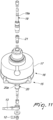
Figure 1 is a front elevation view of a vacuum packaging machine according to the invention; -
Figure 2 is a cross-sectional view taken along the line II-II ofFigure 1 ; -
Figure 3 is a cross-sectional view taken along the line III-III inFigure 2 ; -
Figure 4 is an enlarged-scale view of a detail ofFigure 3 ; -
Figure 5 is a partially exploded perspective view of a heat-sealing bar of the vacuum packaging machine according to the invention with the corresponding linear actuators, and with some parts shown transparent and others omitted for the sake of simplicity; -
Figure 6 is an exploded perspective view of the heat-sealing bar ofFigure 5 ; -
Figure 7 is a perspective view of some components of the heat-sealing bar ofFigure 5 ; -
Figure 8 shows a detail in enlarged scale ofFigure 7 ; -
Figure 9 illustrates another detail in enlarged scale ofFigure 7 ; -
Figure 10 is a perspective view from another angle of the components ofFigure 7 ; -
Figure 11 is a partially exploded perspective view of a first linear actuator of the heat-sealing bar ofFigure 5 ; -
Figure 12 is a partially exploded perspective view of a second linear actuator of the heat-sealing bar ofFigure 5 . - With reference to the figures, the vacuum packaging machine according to the invention, generally designated by the reference numeral 1, comprises a
base structure 2, which defines apackaging chamber 3 which is configured to receive asealable wrapper 4, such as, for example, a bag or a pouch, made of sealable material, designed to contain one or more products to be vacuum packaged, such as, for example, foods or the like. - The
packaging chamber 3 can be, for example, defined by atub 5, which is mounted on thebase structure 2 and which can be closed in an upward region by means of alid 6, which is hinged, conveniently, at one of its ends, to thebase structure 2 and presents, optionally, a typical bell shape. - Inside the
packaging chamber 3, at least one heat-sealing bar 7 and at least onecontrast bar 8 are arranged, which cooperate with each other, face each other, and are, advantageously, arranged in a peripheral region of thepackaging chamber 3. - In particular, with reference to the embodiment illustrated, the (or each) heat-
sealing bar 7 is arranged in a lower region, with respect to therespective contrast bar 8, and is supported by thebase structure 2, while therespective contrast bar 8 is conveniently connected to thelid 6. - More specifically, the heat-
sealing bar 7 can move on command with respect to thecontrast bar 8, between an inactive position, in which the heat-sealing bar 7 and thecontrast bar 8 are mutually spaced apart, in order to allow the insertion, between the heat-sealing bar 7 and thecontrast bar 8, of opposite flaps to be heat-sealed of thewrapper 4 and in order to allow, as a consequence, the sealing thereof, and an active position, in which they are brought mutually close together, in order to allow the compression of the flaps to be heat-sealed of thewrapper 4 between the heat-sealing bar 7 and thecontrast bar 8 and therefore allow the execution of the mutual heat-sealing of the two flaps and the consequent sealing of thewrapper 4. - With reference to the embodiment illustrated, the heat-
sealing bar 7 is mounted on thebase structure 2 with the ability to be moved, with respect to the base structure, in a substantially vertical direction, so that it can be raised, so as to bring it closer to thecontrast bar 8, once thelid 6 is closed, bringing the heat-sealing bar 7 and thecontrast bar 8 accordingly to the active position, or so that it can be lowered, so as to move it away from thecontrast bar 8, bringing the heat-sealing bar 7 and thecontrast bar 8 accordingly to the inactive position. - The heat-
sealing bar 7 comprises at least twoelectric resistances sealing bar 7, so as to affect, with their action, two longitudinal regions, located mutually spaced apart along a substantially horizontal plane, of the heat-sealing surface of the heat-sealing bar 7, intended to come into contact with thewrapper 4. - In particular, each one of the
electric resistances - At least one of the electric resistances, more precisely the electric resistance situated in the position designed to be closest to the inlet of the
wrapper 4, which, in the embodiment illustrated, corresponds to the secondelectric resistance 10, is configured to allow not only the heat-sealing but also the execution of the cutting of thewrapper 4. - The machine according to the invention comprises means for independent
electric power supply 11 of theelectric resistances independent power supply 11 are configured to allow the electric power supply of each one of theelectric resistances - Advantageously, the means for independent
electric power supply 11 comprise at least two separateelectrical input connectors electric resistance sealing bar 7, and each one is configured to supply electric power to the correspondingelectric resistance - More precisely, there is at least one first
electrical input connector 12, configured to supply electric power to the firstelectric resistance 9, and at least one secondelectrical input connector 13, configured to supply electric power to the secondelectric resistance 10. - The means for independent
electric power supply 11 further comprise means for independentelectrical connection 14 of each one of theelectric resistances electrical input connector - In particular, each
electrical input connector electrical input connectors - Conveniently, the electric voltage transformer is controlled by an electronic power controller, not shown, which makes it possible to manage the electric power supply to the
electric resistances electrical input connectors - In more detail, it should be noted that the heat-
sealing bar 7 can be moved, with respect to thecontrast bar 8, by means of movement means 15 which comprise, conveniently, at least one firstlinear actuator 16. - In particular, the first
linear actuator 16 is provided with arespective actuation piston 16a, mounted so that it can slide within afirst actuation cylinder 17 and functionally connected to the heat-sealing bar 7 by way of arespective stem 16b. - Advantageously, the means for independent
electrical connection 14 substantially extend, at least partially, along thestem 16b of the firstlinear actuator 16. - In particular, the means for independent
electrical connection 14 are configured to electrically connect, independently, each one of theelectrical input connectors first end electric resistance - Conveniently, substantially at a
second end first end electric resistances electrical output connector 18, common to both theelectric resistances - In further detail, the
stem 16b of the firstlinear actuator 16 comprises, advantageously, at least two electrically conductingportions reference numeral 19, and at least one second electrically conducting portion, in turn generally designated by thereference numeral 20. - In particular, the first electrically conducting
portion 19 is connected electrically to one of the two electrical input connectors and to one of the electric resistances and, more specifically, it is electrically connected to the firstelectrical input connector 12 and to the firstelectric resistance 9, while the second electrically conductingportion 20 of thestem 16b is electrically connected to the other electrical input connector and to the other electric resistance and, more precisely, to the secondelectrical input connector 13 and to the secondelectric resistance 10. - In this manner, the
stem 16b of the firstlinear actuator 16, by virtue of the fact that it comprises at least two electrically conductingportions electric resistances bar 7, one for the electric resistance that enables execution of the heat-sealing of thewrapper 4, i.e. theelectric resistance 9, and one for the electric resistance that makes it possible to execute the heat-sealing or the cutting of thewrapper 4, i.e. theelectric resistance 10, so as to allow an independent electric power supply of theelectric resistances - Conveniently, the first electrically conducting
portion 19 of thestem 16b substantially extends along the axis of thestem 16b, while the second electrically conductingportion 20 of thestem 16b is arranged coaxially around to the first electrically conductingportion 19. - More specifically, according to the embodiment shown, the first electrically conducting
portion 19 of thestem 16b is constituted by at least one central rod-like body 19a made of conducting material, which extends along the axis of thestem 16b. The second electrically conductingportion 20 of thestem 16b, on the other hand, is provided by at least one sleeve-like body 20a made of conducting material, arranged around the central rod-like body 19a. - Interposed between the first electrically conducting
portion 19 and the second electrically conductingportion 20, at least one electrically insulating body is conveniently provided, which is constituted, for example, by at least oneelectric insulation bushing 21, arranged between the central rod-like body 19a and the sleeve-like body 20a. - It should be noted that both the sleeve-
like body 20a and the central rod-like body 19a can be made in one or more pieces that can be mutually assembled, for example with a threaded connection. - Preferably, at least one of the pieces that make up the central rod-
like body 19a, in particular at least one piece designed to remain, at least partially, in a protruding position with respect to theactuation cylinder 17, can be substituted during the construction of the machine with another of a different length, so as to allow for the possibility of varying the length of thestem 16b in a very convenient manner, by adapting its measurements to the size or version of the machine. - Conveniently, the electrically conducting
portions stem 16b are, furthermore, each electrically connected to at least one respective electricalinput contact element bar 7 and electrically connected to a correspondingelectric resistance - More specifically, the first electrically conducting
portion 19 of thestem 16b is connected to at least one first electricalinput contact element 22, which in turn is electrically connected to the firstelectric resistance 9, while the second electrically conductingportion 20 of thestem 16b is connected to at least one second electricalinput contact element 23, which is different, i.e. electrically isolated, from the firstelectrical contact element 22 and which is instead electrically connected to the secondelectric resistance 10. - Advantageously, as in the embodiment shown, the first electrically conducting
portion 19 of thestem 16b is electrically connected, at one axial end thereof, to the correspondingelectrical input connector 12, while, at the other axial end thereof, it is in contact with an electrically conductingelectrical contact plate 25, which is elastically loaded, by means of aspring 26, against the first electrically conductingportion 19. - Conveniently, the
electrical contact plate 25 is accommodated in a first box-like electrically-insulatingbody 27, which is integrally supported by the heat-sealingbar 7 and which is, advantageously, composed of a pair ofshells - The
contact plate 25 is elastically pushed by thespring 26, so that a face thereof remains in contact against the end of the central rod-like body 19a that is directed toward the heat-sealingbar 7, and is connected, with anelectrical connection portion 25a thereof, suitably positioned outside the first box-like electrically-insulatingbody 27, with the first electricalinput contact element 22, which, advantageously, comprises a first snap-fitelectrical connector 28 which is coupled with theelectrical connection portion 25a of thecontact plate 25. - In turn, the first snap-fit
electrical connector 28 is, conveniently, connected, by means of a firstelectric cable 29, to the firstelectric resistance 9, by means of, for example, a firstelectrical terminal connector 30, to which thefirst end 9a of the firstelectric resistance 9 is connected, so as to obtain the electrical connection between the firstelectric cable 29 and the firstelectric resistance 9. - The second electrically conducting
portion 20 of thestem 16b is, on the other hand, connected, at an axial end thereof, to the correspondingelectrical input connector 13, and, substantially at the opposite axial end thereof, is in a relationship of electrical contact with afirst connector block 31, made of an electrically conductive material, which is integral with the heat-sealingbar 7 and is passed through with play, i.e. without electrical contact, by the first electrically conductingportion 19. - Advantageously, the
first connector block 31 is also accommodated in the first box-like electrically-insulatingbody 27 and has, conveniently, a connectingtab 31a, accessible from outside the first box-like electrically-insulatingbody 27, which allows its connection to the second electricalinput contact element 23, which comprises, conveniently, a second snap-fitelectrical connector 32, which is coupled to the connectingtab 31a of thefirst connector block 31. - In particular, the second snap-fit
electrical connector 32 is connected to the secondelectric resistance 10, for example by means of a secondelectric cable 33, which is, conveniently, connected to a secondelectrical terminal connector 34, electrically separate from the firstelectrical terminal connector 30, to which thefirst end 10a of the secondelectric resistance 10 is also connected, so as to obtain the electrical connection between the secondelectric cable 33 and the secondelectric resistance 10. - In more detail, the
first connector block 31 is arranged so as to face, with one of its sides, toward the face of thecontact plate 25 that is designed to remain in contact with the central rod-like body 19a of thestem 16b and is provided with afirst passage 35 which is axially passed through, so that it can slide axially, by thestem 16b. - The
first passage 35 is, in particular, configured to have greater transverse dimensions than the diameter of the central rod-like body 19a of thestem 16b, so that it can be passed through axially by the central rod-like body 19a of thestem 16b, without the possibility that the central rod-like body 19a of thestem 16b could come into contact with thefirst connector block 31, so that there is no electrical continuity between the first electrically conductingportion 19 of thestem 16b and thefirst connector block 31. - The
first passage 35 is furthermore perimetrically delimited, at least partially, by at least one portion of wall which is in contact, with the ability to slide, with the sleeve-like body 20a of thestem 16b, so as to ensure electrical continuity between the second electrically conductingportion 20 of thestem 16b and thefirst connector block 31. - Advantageously, the movement means 15 for moving the heat-sealing
bar 7, in addition to the firstlinear actuator 16, also comprise at least one secondlinear actuator 38, arranged spaced apart from the firstlinear actuator 16, along the longitudinal axis of the heat-sealingbar 7. - Preferably, to ensure the level movement of the heat-sealing
bar 7, the firstlinear actuator 16 and the secondlinear actuator 38 are arranged substantially mutually symmetrically, with respect to a central portion of the heat-sealingbar 7, located between its opposite ends. - In detail, the second
linear actuator 38 is provided with arespective actuation piston 38a, which is accommodated so that it can slide within asecond actuation cylinder 39, and arespective stem 38b which is functionally connected to the heat-sealingbar 7. - Conveniently, the
stem 38b of the secondlinear actuator 38 is electrically conductive and is connected, with at least one portion thereof, in particular with a portion thereof that is proximate to the end thereof that is connected to the heat-sealingbar 7, to thesecond end electric resistances electric resistances - In detail, the
stem 38b of the secondlinear actuator 38 is constituted by a rod-like element and is electrically connected to the second end of both of theelectric resistances output contact element 40, integral with the heat-sealingbar 7, to which both of theelectric resistances - It should be noted that the rod-like element that constitutes the
stem 38b of the secondlinear actuator 38 can be made in multiple longitudinal pieces or portions assembled together, for example by means of threaded connections, of which at least one can be substituted, during construction of the machine, with another of different length, so as to be able to adapt the length of thestem 38b of the secondlinear actuator 38 as a function of the size or of the version of the machine. - In more detail, the
stem 38b of the secondlinear actuator 38 is in electrical contact with asecond block connector 41, made of electrically conductive material, which is arranged inside a second box-like electrically-insulatingbody 42, which is integrally associated with the heat-sealingbar 7 and conveniently made of twoshells - The
second block connector 41 has asecond passage 43 which can be slideably passed through by thestem 38b of the secondlinear actuator 38. - In particular, the
stem 38b of the secondlinear actuator 38 is in contact with at least one portion of the inner wall of thesecond passage 43, so as to ensure electrical continuity between thesecond block connector 41 and thestem 38b of the secondlinear actuator 38. - Substantially at the opposite end thereof from the end connected to the heat-sealing
bar 7, thestem 38b of the secondlinear actuator 38 is connected electrically to theelectrical output connector 18, which is, in turn, connected electrically to a second pole or terminal connector of the electric voltage transformer. - The
second block connector 41 is in turn connected to thesecond end electric resistances output contact element 40. - In particular, the
second block connector 41 is associated with a correspondingelectric connecting tab 41a, which is accessible from outside the second box-like electrically-insulatingbody 41 and which makes it possible to obtain the electrical connection between thesecond block connector 41 and the electricaloutput contact element 40. - More specifically, the electrical
output contact element 40 comprises a third snap-fitelectrical connector 44, which is coupled to the connecting tab of thesecond block connector 40. - Conveniently, the third snap-fit
electrical connector 44 is electrically connected, with an end thereof, to two electrical cables, respectively a third and a fourthelectrical cable - At the opposite end thereof, the third
electrical cable 45 is connected to a third electricalterminal connector 47, which is also connected to thesecond end 9b of the firstelectric resistance 9, while the fourthelectrical cable 46 is connected to a fourth electricalterminal connector 48, which in turn is also connected to thesecond end 10b of the secondelectric resistance 10. - For completeness, it must be noted that the
packaging chamber 3 is connected, in a manner per se known, to vacuum generation means, which are constituted, conveniently, by a vacuum pump, not shown, which is configured to extract the air from thepackaging chamber 3. - Advantageously, the vacuum pump is connected to the first and to the second
linear actuator packaging chamber 3 can be used to actuate thepistons linear actuators bar 7. - Conveniently, interposed between the
pistons linear actuator 16 and of the secondlinear actuator 38 and the correspondingcylinders pistons bar 7, under the thrust of the pressure of the air introduced into thecylinders bar 7, once the action of the pressure of the air on thepistons - It should also be noted, as shown in
Figure 2 , that inside thepackaging chamber 3 there can optionally be two heat-sealingbars 7 which are arranged, with therespective contrast bars 8, at two opposite ends of thepackaging chamber 3. - The operation of the machine, according to the invention, is the following.
- A
wrapper 4, containing the products to be vacuum packaged, is placed inside thepackaging chamber 3 and a portion of thewrapper 4 proximate to its inlet is arranged on the heat-sealingbar 7. - Then the
packaging chamber 3 is closed by means of thelid 6 and the vacuum generation means are activated, so as to extract the air from thepackaging chamber 3 and, therefore, from thewrapper 4. - Once the desired level of vacuum is obtained, the operator proceeds with the sealing of the
wrapper 4. - In particular, the heat-sealing
bar 7 is thrust upward by thestems linear actuator wrapper 4 and the latter in abutment against thecontrast bar 8. - The lifting force of the heat-sealing
bar 7 is generated using the difference in pressure between the inside of thepackaging chamber 3 and the external, atmospheric pressure. - At the command of the electronic power controller, the electrical power supplies to the
electric resistances bar 7 are switched on, through thestems linear actuators - In particular, the voltage transformer powers, with its first pole, the first
electrical input connector 12 and the secondelectrical input connector 13 and thestem 16b of the firstlinear actuator 16 brings the two separate power supplies of the first and of the secondelectrical input connector electric resistances portions portion 19 powering the firstelectric resistance 9 i.e. the electric resistance that makes it possible to execute the heat-sealing of thewrapper 4 and with the second electrically conductingportion 20 powering the secondelectric resistance 10 i.e. the electric resistance that makes it possible to execute both the cutting and the heat-sealing of thewrapper 4. - The
stem 38b of the secondlinear actuator 38 closes the electrical circuit by connecting thesecond end electric resistances electrical output connector 18. - In this manner, the voltage transformer powers the
electric resistances bar 7 for a short time. - As a function of the current dispensed and of the dispensing time, the second
electric resistance 10 executes the cutting of thewrapper 4 or only the heat-sealing thereof, while the sole function of the firstelectric resistance 9 is to execute the heat-sealing of thewrapper 4. - Once the heat-sealing of the
wrapper 4 has been executed, atmospheric pressure is restored in thepackaging chamber 3 and, after thepackaging chamber 3 is opened by lifting thelid 6, and the sealedwrapper 4 containing the vacuum-packaged products is removed from thepackaging chamber 3. - In practice it has been found that the invention fully achieves the intended aim and objects by providing a vacuum packaging machine that makes it possible to simultaneously handle both the heat-sealing function and the cutting function of wrappers used for vacuum packaging, with considerable simplification of the packaging operations.
- Another advantage of the machine according to the invention is that it makes it possible to execute a heat-sealing of packaging wrappers that is capable of positively ensuring the vacuum seal even if the thickness of the wrappers varies and if the wrappers are made from different materials.
- Another advantage of the machine according to the invention is that it makes it possible, differently from the prior art, to separately manage the power supply voltage and the heat-sealing time of the heat-sealing bar.
- The invention, thus conceived, is susceptible of numerous modifications and variations, all of which are within the scope of the appended claims. Moreover, all the details may be substituted by other, technically equivalent elements.
- In practice the materials employed, provided they are compatible with the specific use, and the contingent dimensions and shapes, may be any according to requirements and to the state of the art.
- The disclosures in
Italian Patent Application No. 102023000006462 - Where technical features mentioned in any claim are followed by reference signs, such reference signs have been inserted for the sole purpose of increasing the intelligibility of the claims and accordingly such reference signs do not have any limiting effect on the interpretation of each element identified by way of example by such reference signs.
Claims (11)
- A food vacuum packaging machine, comprising a base structure (2) which defines a packaging chamber (3) configured to receive a sealable wrapper (4) containing the products to be vacuum packaged, inside said packaging chamber (3) there being arranged at least one heat-sealing bar (7) and at least one respective contrast bar (8), which face each other and can move on command, with respect to each other, between an inactive position, in which they are mutually spaced apart, to allow the insertion, between said heat-sealing bar (7) and said contrast bar (8), of opposite flaps to be heat-sealed of said wrapper (4), and an active position, in which they are mutually close together, to allow the compression of said flaps between said heat-sealing bar (7) and said contrast bar (8), said heat-sealing bar (7) comprising at least two electric resistances (9, 10) which are parallel to each other and spaced apart, extending longitudinally along the extension of said heat-sealing bar (7), at least one of said electric resistances (9, 10) being configured to allow the execution of the cutting of said wrapper (4), characterized in that it comprises means for independent electric power supply (11) to said electric resistances (9, 10) which are configured to supply electric power to each one of said electric resistances (9, 10) independently of each other.
- The vacuum packaging machine according to claim 1, characterized in that said means for independent electric power supply (11) comprise means for independent electrical connection (14) of each one of said electric resistances (8, 9) to a respective electrical input connector (12, 13) configured to supply electric power to the respective electric resistance.
- The vacuum packaging machine according to claim 2, characterized in that said heat-sealing bar (7) can be actuated in movement, with respect to said contrast bar (8), by virtue of movement means (15) comprising at least one first linear actuator (16), said at least one first linear actuator (16) having an actuation piston (16a) which is functionally connected to said at least one of said heat-sealing bars (7) by means of a respective stem (16b), said means for independent electrical connection (14) extending, at least partly, substantially along said stem (16b).
- The vacuum packaging machine according to one or more of the preceding claims, characterized in that said means for independent electrical connection (14) are configured to electrically connect each one of said electrical input connectors (12, 13) to a first end (9a, 10a) of the respective electric resistance (9, 10), said electric resistances (9, 10) each being electrically connected, at a second end (9b, 10b), opposite to said first end (9a, 10a), to a single electrical output connector (18).
- The vacuum packaging machine according to one or more of the preceding claims, characterized in that said stem (16b) of said first linear actuator (16) comprises at least two electrically conducting portions (19, 20) which are electrically isolated from each other, respectively at least one first electrically conducting portion (19) and at least one second electrically conducting portion (20), said first electrically conducting portion (19) being electrically connected to one of said electrical input connectors (12, 13) and to one of said electric resistances (9, 10), said at least one second electrically conducting portion (20) of said stem (16b) being electrically connected to the other electrical input connector (12, 13) and to the other electric resistance (9, 10).
- The vacuum packaging machine according to one or more of the preceding claims, characterized in that said at least one first electrically conducting portion (19) of said stem (16b) of said first linear actuator (16) extends substantially along the axis of said stem (16b), said at least one second electrically conducting portion (20) being arranged coaxially around said at least one first electrically conducting portion (19).
- The vacuum packaging machine according to one or more of the preceding claims, characterized in that said first electrically conducting portion (19) of said stem (16b) comprises at least one central rod-like body (19a) which extends along the axis of said stem (16b), said second electrically conducting portion (20) of said stem (16b) comprising at least one sleeve-like body (20a) arranged around said central rod-like body (19a).
- The vacuum packaging machine according to one or more of the preceding claims, characterized in that said electrically conducting portions (19, 20) of said stem (16b) are each electrically connected to at least one respective electrical input contact element (22, 23), which is integral with said heat-sealing bar (7) and electrically connected to a corresponding electric resistance (9, 10).
- The vacuum packaging machine according to one or more of the preceding claims, characterized in that said first electrically conducting portion (19) of said stem (16b) is electrically connected, at one axial end thereof, to the corresponding electrical input connector (12, 13) and, at the other axial end thereof, is in contact with an electrically conducting electrical contact plate (25), which is elastically loaded against said first electrically conducting portion (19).
- The vacuum packaging machine according to one or more of the preceding claims, characterized in that said second electrically conducting portion (20) is connected, at one axial end thereof, to the corresponding electrical input connector (12, 13), and is, substantially at the opposite axial end thereof, in a relationship of electrical contact with a first connector block (31), which is integral with said heat-sealing bar (7) and is passed through with play by said first electrically conducting portion (19).
- The vacuum packaging machine according to one or more of the preceding claims, characterized in that said movement means (15) for moving said heat-sealing bar (7) comprise at least one second linear actuator (38) which is arranged spaced apart from said at least one first linear actuator (16) along the axis of said heat-sealing bar (7), said at least one second linear actuator (38) having a respective actuation piston (38a) and a respective stem (38b) which is functionally connected to said heat-sealing bar (7), the stem (38b) of said at least one second linear actuator (38) being electrically conducting and being connected, substantially at one end thereof, to the second end (9b, 10b) of both said electric resistances (9, 10).
Applications Claiming Priority (1)
| Application Number | Priority Date | Filing Date | Title |
|---|---|---|---|
| IT202300006462 | 2023-04-03 |
Publications (1)
| Publication Number | Publication Date |
|---|---|
| EP4442438A1 true EP4442438A1 (en) | 2024-10-09 |
Family
ID=86942651
Family Applications (1)
| Application Number | Title | Priority Date | Filing Date |
|---|---|---|---|
| EP24167334.2A Pending EP4442438A1 (en) | 2023-04-03 | 2024-03-28 | Vacuum packaging machine |
Country Status (1)
| Country | Link |
|---|---|
| EP (1) | EP4442438A1 (en) |
Citations (3)
| Publication number | Priority date | Publication date | Assignee | Title |
|---|---|---|---|---|
| US5239808A (en) * | 1992-05-13 | 1993-08-31 | Hantover, Inc. | Vacuum packaging machine |
| US8099931B2 (en) * | 2008-04-18 | 2012-01-24 | Multivac Sepp Haggenmueller Gmbh & Co. Kg | Method and device for packaging of bulk goods in bags |
| US20150027089A1 (en) * | 2012-10-22 | 2015-01-29 | Sunbeam Products, Inc. | Vacuum Packaging and Sealing Appliance with Cooling Fan |
-
2024
- 2024-03-28 EP EP24167334.2A patent/EP4442438A1/en active Pending
Patent Citations (3)
| Publication number | Priority date | Publication date | Assignee | Title |
|---|---|---|---|---|
| US5239808A (en) * | 1992-05-13 | 1993-08-31 | Hantover, Inc. | Vacuum packaging machine |
| US8099931B2 (en) * | 2008-04-18 | 2012-01-24 | Multivac Sepp Haggenmueller Gmbh & Co. Kg | Method and device for packaging of bulk goods in bags |
| US20150027089A1 (en) * | 2012-10-22 | 2015-01-29 | Sunbeam Products, Inc. | Vacuum Packaging and Sealing Appliance with Cooling Fan |
Similar Documents
| Publication | Publication Date | Title |
|---|---|---|
| US2963838A (en) | Film sealing mechanism for packaging machines | |
| CN109515828A (en) | Vacuum closing apparatus with two-stage sealing | |
| EP4442438A1 (en) | Vacuum packaging machine | |
| CN107867428B (en) | Vacuum packaging sealing machine | |
| JP4842976B2 (en) | Power socket device with permission switch | |
| US5347248A (en) | Protective switching device for difference-current and undervoltage tripping | |
| KR102471069B1 (en) | Under vacuum cooking appliance | |
| JP6212298B2 (en) | Heat sealing device | |
| CN107934010B (en) | Vacuum packaging sealing device | |
| EP0746999A2 (en) | Control device, particularly for steam-generating appliances for household and/or industrial cleaning | |
| JP4115944B2 (en) | Electric appliance | |
| JP4455437B2 (en) | Vacuum packaging machine | |
| CN107902133B (en) | Vacuum packaging equipment | |
| JPH10236428A (en) | Vacuum packaging device | |
| JP2001130511A (en) | Vacuum packaging device | |
| KR20110045792A (en) | Vinyl sliding type sealing apparatus, Air suction pump having the same and Sealing method using the same | |
| EP1379435B1 (en) | Portable vacuum packaging machine | |
| JPH04114611A (en) | Vacuum cooker | |
| US2465310A (en) | Sealer | |
| KR100779755B1 (en) | Automatic Apparatus for Vacuuming and Sealing A Packing Bag | |
| KR20210090937A (en) | Vacuum circuit breaker | |
| KR101865004B1 (en) | A household vacuum packing machine in which vacuum pressure is released by the unclamping button | |
| ITMI20000454A1 (en) | CONTROL DEVICE FOR AN ELECTRICAL APPLIANCE, IN PARTICULAR FOR A DRYER OR OTHER HOUSEHOLD APPLIANCES | |
| WO2010073285A1 (en) | "device for creating a vacuum in containers to preserve vacuum-packed products" | |
| KR200293233Y1 (en) | Heat Sealing Device |
Legal Events
| Date | Code | Title | Description |
|---|---|---|---|
| PUAI | Public reference made under article 153(3) epc to a published international application that has entered the european phase |
Free format text: ORIGINAL CODE: 0009012 |
|
| STAA | Information on the status of an ep patent application or granted ep patent |
Free format text: STATUS: THE APPLICATION HAS BEEN PUBLISHED |
|
| AK | Designated contracting states |
Kind code of ref document: A1 Designated state(s): AL AT BE BG CH CY CZ DE DK EE ES FI FR GB GR HR HU IE IS IT LI LT LU LV MC ME MK MT NL NO PL PT RO RS SE SI SK SM TR |