EP2605002B1 - Method for reconstructing the optical properties of a scattering medium using a combination of a plurality of Mellin-Laplace transforms of a magnitude comprising a time distribution of a received signal, and associated reconstruction system - Google Patents
Method for reconstructing the optical properties of a scattering medium using a combination of a plurality of Mellin-Laplace transforms of a magnitude comprising a time distribution of a received signal, and associated reconstruction system Download PDFInfo
- Publication number
- EP2605002B1 EP2605002B1 EP12197003.2A EP12197003A EP2605002B1 EP 2605002 B1 EP2605002 B1 EP 2605002B1 EP 12197003 A EP12197003 A EP 12197003A EP 2605002 B1 EP2605002 B1 EP 2605002B1
- Authority
- EP
- European Patent Office
- Prior art keywords
- medium
- mellin
- detector
- source
- distribution
- Prior art date
- Legal status (The legal status is an assumption and is not a legal conclusion. Google has not performed a legal analysis and makes no representation as to the accuracy of the status listed.)
- Active
Links
- 238000009826 distribution Methods 0.000 title claims description 84
- 230000003287 optical effect Effects 0.000 title claims description 41
- 238000000034 method Methods 0.000 title claims description 36
- 238000009792 diffusion process Methods 0.000 claims description 34
- 230000005855 radiation Effects 0.000 claims description 21
- 238000010521 absorption reaction Methods 0.000 claims description 18
- 238000012545 processing Methods 0.000 claims description 7
- 238000005316 response function Methods 0.000 claims description 4
- 230000002829 reductive effect Effects 0.000 claims description 3
- 230000031700 light absorption Effects 0.000 claims 1
- 230000006870 function Effects 0.000 description 39
- 230000004044 response Effects 0.000 description 18
- 230000002123 temporal effect Effects 0.000 description 17
- 238000001514 detection method Methods 0.000 description 12
- 239000013598 vector Substances 0.000 description 11
- 230000005284 excitation Effects 0.000 description 10
- 239000000523 sample Substances 0.000 description 10
- 238000004364 calculation method Methods 0.000 description 9
- 238000005259 measurement Methods 0.000 description 9
- 239000011159 matrix material Substances 0.000 description 8
- 239000013307 optical fiber Substances 0.000 description 8
- 238000003384 imaging method Methods 0.000 description 7
- 239000000835 fiber Substances 0.000 description 6
- 238000005286 illumination Methods 0.000 description 5
- 239000006096 absorbing agent Substances 0.000 description 4
- 230000003111 delayed effect Effects 0.000 description 4
- 238000003745 diagnosis Methods 0.000 description 4
- 210000000056 organ Anatomy 0.000 description 4
- 230000008569 process Effects 0.000 description 4
- 230000035945 sensitivity Effects 0.000 description 4
- 206010028980 Neoplasm Diseases 0.000 description 3
- 238000000149 argon plasma sintering Methods 0.000 description 3
- 210000000481 breast Anatomy 0.000 description 3
- 238000004422 calculation algorithm Methods 0.000 description 3
- 238000011161 development Methods 0.000 description 3
- 230000001079 digestive effect Effects 0.000 description 3
- 230000014509 gene expression Effects 0.000 description 3
- 230000015654 memory Effects 0.000 description 3
- 210000001519 tissue Anatomy 0.000 description 3
- ZOKXUAHZSKEQSS-UHFFFAOYSA-N tribufos Chemical compound CCCCSP(=O)(SCCCC)SCCCC ZOKXUAHZSKEQSS-UHFFFAOYSA-N 0.000 description 3
- 241000282414 Homo sapiens Species 0.000 description 2
- 210000004556 brain Anatomy 0.000 description 2
- 229940082150 encore Drugs 0.000 description 2
- 230000001965 increasing effect Effects 0.000 description 2
- 230000010365 information processing Effects 0.000 description 2
- 210000002307 prostate Anatomy 0.000 description 2
- 238000004613 tight binding model Methods 0.000 description 2
- 238000001161 time-correlated single photon counting Methods 0.000 description 2
- 238000003325 tomography Methods 0.000 description 2
- 206010006187 Breast cancer Diseases 0.000 description 1
- 208000026310 Breast neoplasm Diseases 0.000 description 1
- 206010061218 Inflammation Diseases 0.000 description 1
- 241001465754 Metazoa Species 0.000 description 1
- 240000005561 Musa balbisiana Species 0.000 description 1
- 235000018290 Musa x paradisiaca Nutrition 0.000 description 1
- 206010060862 Prostate cancer Diseases 0.000 description 1
- 208000000236 Prostatic Neoplasms Diseases 0.000 description 1
- 230000008901 benefit Effects 0.000 description 1
- 230000005540 biological transmission Effects 0.000 description 1
- 201000011510 cancer Diseases 0.000 description 1
- 238000012512 characterization method Methods 0.000 description 1
- 238000006243 chemical reaction Methods 0.000 description 1
- 238000002939 conjugate gradient method Methods 0.000 description 1
- 238000000354 decomposition reaction Methods 0.000 description 1
- 238000002059 diagnostic imaging Methods 0.000 description 1
- 230000009975 flexible effect Effects 0.000 description 1
- 230000004054 inflammatory process Effects 0.000 description 1
- 238000004519 manufacturing process Methods 0.000 description 1
- 238000010606 normalization Methods 0.000 description 1
- 238000003672 processing method Methods 0.000 description 1
- 230000002441 reversible effect Effects 0.000 description 1
- 230000000630 rising effect Effects 0.000 description 1
- 230000007704 transition Effects 0.000 description 1
Images


Classifications
-
- A—HUMAN NECESSITIES
- A61—MEDICAL OR VETERINARY SCIENCE; HYGIENE
- A61B—DIAGNOSIS; SURGERY; IDENTIFICATION
- A61B5/00—Measuring for diagnostic purposes; Identification of persons
- A61B5/0059—Measuring for diagnostic purposes; Identification of persons using light, e.g. diagnosis by transillumination, diascopy, fluorescence
- A61B5/0071—Measuring for diagnostic purposes; Identification of persons using light, e.g. diagnosis by transillumination, diascopy, fluorescence by measuring fluorescence emission
-
- G—PHYSICS
- G01—MEASURING; TESTING
- G01N—INVESTIGATING OR ANALYSING MATERIALS BY DETERMINING THEIR CHEMICAL OR PHYSICAL PROPERTIES
- G01N21/00—Investigating or analysing materials by the use of optical means, i.e. using sub-millimetre waves, infrared, visible or ultraviolet light
- G01N21/17—Systems in which incident light is modified in accordance with the properties of the material investigated
- G01N21/59—Transmissivity
-
- A—HUMAN NECESSITIES
- A61—MEDICAL OR VETERINARY SCIENCE; HYGIENE
- A61B—DIAGNOSIS; SURGERY; IDENTIFICATION
- A61B5/00—Measuring for diagnostic purposes; Identification of persons
- A61B5/0059—Measuring for diagnostic purposes; Identification of persons using light, e.g. diagnosis by transillumination, diascopy, fluorescence
- A61B5/0073—Measuring for diagnostic purposes; Identification of persons using light, e.g. diagnosis by transillumination, diascopy, fluorescence by tomography, i.e. reconstruction of 3D images from 2D projections
-
- A—HUMAN NECESSITIES
- A61—MEDICAL OR VETERINARY SCIENCE; HYGIENE
- A61B—DIAGNOSIS; SURGERY; IDENTIFICATION
- A61B5/00—Measuring for diagnostic purposes; Identification of persons
- A61B5/72—Signal processing specially adapted for physiological signals or for diagnostic purposes
- A61B5/7235—Details of waveform analysis
- A61B5/7253—Details of waveform analysis characterised by using transforms
-
- G—PHYSICS
- G01—MEASURING; TESTING
- G01N—INVESTIGATING OR ANALYSING MATERIALS BY DETERMINING THEIR CHEMICAL OR PHYSICAL PROPERTIES
- G01N21/00—Investigating or analysing materials by the use of optical means, i.e. using sub-millimetre waves, infrared, visible or ultraviolet light
- G01N21/17—Systems in which incident light is modified in accordance with the properties of the material investigated
- G01N21/47—Scattering, i.e. diffuse reflection
- G01N21/4795—Scattering, i.e. diffuse reflection spatially resolved investigating of object in scattering medium
-
- G—PHYSICS
- G01—MEASURING; TESTING
- G01N—INVESTIGATING OR ANALYSING MATERIALS BY DETERMINING THEIR CHEMICAL OR PHYSICAL PROPERTIES
- G01N21/00—Investigating or analysing materials by the use of optical means, i.e. using sub-millimetre waves, infrared, visible or ultraviolet light
- G01N21/17—Systems in which incident light is modified in accordance with the properties of the material investigated
- G01N21/47—Scattering, i.e. diffuse reflection
- G01N21/49—Scattering, i.e. diffuse reflection within a body or fluid
-
- G—PHYSICS
- G01—MEASURING; TESTING
- G01N—INVESTIGATING OR ANALYSING MATERIALS BY DETERMINING THEIR CHEMICAL OR PHYSICAL PROPERTIES
- G01N21/00—Investigating or analysing materials by the use of optical means, i.e. using sub-millimetre waves, infrared, visible or ultraviolet light
- G01N21/62—Systems in which the material investigated is excited whereby it emits light or causes a change in wavelength of the incident light
- G01N21/63—Systems in which the material investigated is excited whereby it emits light or causes a change in wavelength of the incident light optically excited
- G01N21/64—Fluorescence; Phosphorescence
- G01N21/6408—Fluorescence; Phosphorescence with measurement of decay time, time resolved fluorescence
-
- G—PHYSICS
- G01—MEASURING; TESTING
- G01N—INVESTIGATING OR ANALYSING MATERIALS BY DETERMINING THEIR CHEMICAL OR PHYSICAL PROPERTIES
- G01N21/00—Investigating or analysing materials by the use of optical means, i.e. using sub-millimetre waves, infrared, visible or ultraviolet light
- G01N21/62—Systems in which the material investigated is excited whereby it emits light or causes a change in wavelength of the incident light
- G01N21/63—Systems in which the material investigated is excited whereby it emits light or causes a change in wavelength of the incident light optically excited
- G01N21/64—Fluorescence; Phosphorescence
- G01N21/6428—Measuring fluorescence of fluorescent products of reactions or of fluorochrome labelled reactive substances, e.g. measuring quenching effects, using measuring "optrodes"
-
- G—PHYSICS
- G01—MEASURING; TESTING
- G01N—INVESTIGATING OR ANALYSING MATERIALS BY DETERMINING THEIR CHEMICAL OR PHYSICAL PROPERTIES
- G01N21/00—Investigating or analysing materials by the use of optical means, i.e. using sub-millimetre waves, infrared, visible or ultraviolet light
- G01N21/62—Systems in which the material investigated is excited whereby it emits light or causes a change in wavelength of the incident light
- G01N21/63—Systems in which the material investigated is excited whereby it emits light or causes a change in wavelength of the incident light optically excited
- G01N21/64—Fluorescence; Phosphorescence
- G01N21/645—Specially adapted constructive features of fluorimeters
- G01N21/6456—Spatial resolved fluorescence measurements; Imaging
-
- G—PHYSICS
- G06—COMPUTING; CALCULATING OR COUNTING
- G06T—IMAGE DATA PROCESSING OR GENERATION, IN GENERAL
- G06T11/00—2D [Two Dimensional] image generation
- G06T11/003—Reconstruction from projections, e.g. tomography
-
- A—HUMAN NECESSITIES
- A61—MEDICAL OR VETERINARY SCIENCE; HYGIENE
- A61B—DIAGNOSIS; SURGERY; IDENTIFICATION
- A61B5/00—Measuring for diagnostic purposes; Identification of persons
- A61B5/40—Detecting, measuring or recording for evaluating the nervous system
- A61B5/4058—Detecting, measuring or recording for evaluating the nervous system for evaluating the central nervous system
- A61B5/4064—Evaluating the brain
-
- A—HUMAN NECESSITIES
- A61—MEDICAL OR VETERINARY SCIENCE; HYGIENE
- A61B—DIAGNOSIS; SURGERY; IDENTIFICATION
- A61B5/00—Measuring for diagnostic purposes; Identification of persons
- A61B5/42—Detecting, measuring or recording for evaluating the gastrointestinal, the endocrine or the exocrine systems
- A61B5/4222—Evaluating particular parts, e.g. particular organs
- A61B5/4255—Intestines, colon or appendix
-
- A—HUMAN NECESSITIES
- A61—MEDICAL OR VETERINARY SCIENCE; HYGIENE
- A61B—DIAGNOSIS; SURGERY; IDENTIFICATION
- A61B5/00—Measuring for diagnostic purposes; Identification of persons
- A61B5/43—Detecting, measuring or recording for evaluating the reproductive systems
- A61B5/4306—Detecting, measuring or recording for evaluating the reproductive systems for evaluating the female reproductive systems, e.g. gynaecological evaluations
- A61B5/4312—Breast evaluation or disorder diagnosis
-
- A—HUMAN NECESSITIES
- A61—MEDICAL OR VETERINARY SCIENCE; HYGIENE
- A61B—DIAGNOSIS; SURGERY; IDENTIFICATION
- A61B5/00—Measuring for diagnostic purposes; Identification of persons
- A61B5/43—Detecting, measuring or recording for evaluating the reproductive systems
- A61B5/4375—Detecting, measuring or recording for evaluating the reproductive systems for evaluating the male reproductive system
- A61B5/4381—Prostate evaluation or disorder diagnosis
-
- G—PHYSICS
- G01—MEASURING; TESTING
- G01N—INVESTIGATING OR ANALYSING MATERIALS BY DETERMINING THEIR CHEMICAL OR PHYSICAL PROPERTIES
- G01N21/00—Investigating or analysing materials by the use of optical means, i.e. using sub-millimetre waves, infrared, visible or ultraviolet light
- G01N21/17—Systems in which incident light is modified in accordance with the properties of the material investigated
- G01N2021/178—Methods for obtaining spatial resolution of the property being measured
- G01N2021/1785—Three dimensional
- G01N2021/1787—Tomographic, i.e. computerised reconstruction from projective measurements
-
- G—PHYSICS
- G01—MEASURING; TESTING
- G01N—INVESTIGATING OR ANALYSING MATERIALS BY DETERMINING THEIR CHEMICAL OR PHYSICAL PROPERTIES
- G01N21/00—Investigating or analysing materials by the use of optical means, i.e. using sub-millimetre waves, infrared, visible or ultraviolet light
- G01N21/62—Systems in which the material investigated is excited whereby it emits light or causes a change in wavelength of the incident light
- G01N21/63—Systems in which the material investigated is excited whereby it emits light or causes a change in wavelength of the incident light optically excited
- G01N21/64—Fluorescence; Phosphorescence
- G01N21/6408—Fluorescence; Phosphorescence with measurement of decay time, time resolved fluorescence
- G01N2021/6413—Distinction short and delayed fluorescence or phosphorescence
-
- G—PHYSICS
- G01—MEASURING; TESTING
- G01N—INVESTIGATING OR ANALYSING MATERIALS BY DETERMINING THEIR CHEMICAL OR PHYSICAL PROPERTIES
- G01N21/00—Investigating or analysing materials by the use of optical means, i.e. using sub-millimetre waves, infrared, visible or ultraviolet light
- G01N21/62—Systems in which the material investigated is excited whereby it emits light or causes a change in wavelength of the incident light
- G01N21/63—Systems in which the material investigated is excited whereby it emits light or causes a change in wavelength of the incident light optically excited
- G01N21/64—Fluorescence; Phosphorescence
- G01N21/645—Specially adapted constructive features of fluorimeters
- G01N2021/6484—Optical fibres
-
- G—PHYSICS
- G01—MEASURING; TESTING
- G01N—INVESTIGATING OR ANALYSING MATERIALS BY DETERMINING THEIR CHEMICAL OR PHYSICAL PROPERTIES
- G01N2201/00—Features of devices classified in G01N21/00
- G01N2201/06—Illumination; Optics
- G01N2201/069—Supply of sources
- G01N2201/0696—Pulsed
- G01N2201/0697—Pulsed lasers
-
- G—PHYSICS
- G01—MEASURING; TESTING
- G01N—INVESTIGATING OR ANALYSING MATERIALS BY DETERMINING THEIR CHEMICAL OR PHYSICAL PROPERTIES
- G01N2201/00—Features of devices classified in G01N21/00
- G01N2201/08—Optical fibres; light guides
- G01N2201/0826—Fibre array at source, distributing
-
- G—PHYSICS
- G01—MEASURING; TESTING
- G01N—INVESTIGATING OR ANALYSING MATERIALS BY DETERMINING THEIR CHEMICAL OR PHYSICAL PROPERTIES
- G01N2201/00—Features of devices classified in G01N21/00
- G01N2201/08—Optical fibres; light guides
- G01N2201/0833—Fibre array at detector, resolving
-
- G—PHYSICS
- G09—EDUCATION; CRYPTOGRAPHY; DISPLAY; ADVERTISING; SEALS
- G09B—EDUCATIONAL OR DEMONSTRATION APPLIANCES; APPLIANCES FOR TEACHING, OR COMMUNICATING WITH, THE BLIND, DEAF OR MUTE; MODELS; PLANETARIA; GLOBES; MAPS; DIAGRAMS
- G09B23/00—Models for scientific, medical, or mathematical purposes, e.g. full-sized devices for demonstration purposes
- G09B23/28—Models for scientific, medical, or mathematical purposes, e.g. full-sized devices for demonstration purposes for medicine
- G09B23/286—Models for scientific, medical, or mathematical purposes, e.g. full-sized devices for demonstration purposes for medicine for scanning or photography techniques, e.g. X-rays, ultrasonics
Definitions
- the invention also relates to such a reconstruction system.
- the invention is particularly in the field of medical instrumentation, and in particular in the field of optical diffusion imaging applied to biological tissues.
- the invention applies to the detection of various pathologies, such as cancers of the breast, the prostate or even the digestive tract, breast or brain.
- the invention also applies to dermatology, in particular to the characterization of a cutaneous inflammation reaction.
- EP 1 884 765 A1 discloses a method of reconstructing optical properties of a medium, using a reconstruction system comprising a radiation source adapted to illuminate the medium and a detector adapted to receive a signal emitted by the medium.
- the reconstruction method comprises the illumination of the medium by the source, the reception, by the detector, of a signal emitted by the medium, and the development for the source-detector pair of a first distribution of the signal received by the detector, namely the fluorescence signal.
- EP 1 884 765 A1 also describes the calculation of a Mellin-Laplace transform of fluorescence signals or the calculation of higher order moments of normalized fluorescence functions.
- the aim of the invention is therefore to propose a method for reconstructing the optical properties of a scattering medium as well as a reconstruction system using advantageously the Mellin Laplace transform, in particular allowing access to diffusion optical properties that are usually difficult to establish, and for example the spatial distribution of the absorption or diffusion coefficients of a medium.
- the subject of the invention is a method of reconstruction of the aforementioned type, characterized in that the calculation step comprises the calculation of a plurality of Mellin-Laplace transforms of said magnitude for values distinct from the order, and in that the reconstruction step is performed from a combination of the plurality of Mellin-Laplace transforms.
- the reconstruction system further comprises calculation means capable of calculating at least one Mellin-Laplace transform of said quantity for a value of the order greater than or equal to 5, preferably greater than or equal to 8.
- a reconstruction system 10 is intended to perform an examination of a medium 12 via the acquisition of an image of the medium 12, and then the processing of this image.
- the reconstruction system 10 comprises a plurality of radiation sources 14 capable of illuminating the medium 12 and a plurality of detectors 16 capable of receiving a signal emitted by the medium 12.
- the radiation sources 14 and the detectors 16 are, for example , arranged in a probe, not shown.
- the system 10 includes an information processing unit 18 and a screen 20 for displaying an image of the medium.
- the system 10 is a time system, and each radiation source 14 is a source of pulsed radiation.
- Each detector 16 is a time-resolved detector, that is to say a detector for measuring the temporal distribution of the arrival time of photons, also called TCSPC ( Time-Correlated Single Photon Counting).
- the medium 12 has an observation surface 22, in the form of a plane parallel to a longitudinal axis X and a transverse axis Y, and in contact with which the sources 14 and the detectors 16 are suitable for to be applied.
- the middle 12 has an observation direction 24 extending along a vertical axis Z and substantially perpendicular to the observation surface 22.
- the medium 12 is a medium to be characterized, noted MC and visible on the figure 1 .
- the medium to be characterized MC comprises biological tissues of an animal or man.
- the medium to be characterized MC is, for example, an area of an organ such as the brain, a breast, the prostate, the digestive tract or other organs in which fluorophores are likely to be injected.
- the medium to be characterized MC is a biological medium, for example an organ, which one wishes to determine optical diffusion properties and in particular the spatial distribution of coefficients such as the absorption coefficient or the diffusion coefficient.
- the medium to be characterized MC is a diffusing medium containing inclusions whose optical properties of absorption or diffusion are different from those of the medium. 26, only one inclusion 26 is represented on the figure 1 for the clarity of the drawing.
- Each source of pulsed radiation 14 comprises a pulsed light source 28 and an excitation optical fiber 30 connected to the pulsed source 28 for the transmission of the light pulse to the middle 12.
- an excitation optical fiber 30 connected to the pulsed source 28 for the transmission of the light pulse to the middle 12.
- each source of pulsed radiation 14 comprises an optical excitation fiber 30 connected to a single pulsed light source common to the plurality of radiation sources 14.
- the system 10 further comprises an optical switch or a multiplexer for selecting the excitation fiber 30 in which the light beam is sent.
- the set of sources of pulsed radiation 14 is formed of a single pulsed light source and a MEMS-type mirror device (of the English MicroElectroMechanical Systems ), not shown, for scanning the medium 12 with the light from the pulsed light source.
- the source 14 is a multiplexed source, delivering light pulses at different wavelengths.
- the wavelength of each source pulsed radiation 14 is preferably in the visible or near infrared range, that is to say between 500 nm and 1300 nm.
- the repetition rate is about 50 MHz, and generally between 10 MHz and 100 MHz.
- each pulsed radiation source 14 has a duration of between 10 picoseconds and 1 nanosecond, preferably between 10 picoseconds and 100 picoseconds, each pulsed light source 28 being capable of generating a pulse of time width of duration of between 10 picoseconds. and 1 nanosecond, preferably 10 picoseconds to 100 picoseconds.
- Each time-resolved detector 16 also denoted d, comprises a detection optical fiber 32 connected to a time-resolved detection module 34.
- a detection optical fiber 32 connected to a time-resolved detection module 34.
- the free end of this detection optical fiber 32 is assimilated to the detector d.
- the detection module 34 comprises a detection member 36 for each detector 16.
- the detection module 34 comprises a detection member common to several detectors 16, in particular a single detection member for all the detectors. detectors 16.
- the detection member 36 is, for example, a photomultiplier or an avalanche photodiode, also called APD (Avalanche Photodiode English), a photodiode or single photon avalanche also SPAD (English Single- Photon Avalanche Diode) or an image intensifier tube having one or more anodes (of the English Multi-Channel Plate ) .
- APD Avalanche Photodiode English
- SPAD English Single- Photon Avalanche Diode
- image intensifier tube having one or more anodes (of the English Multi-Channel Plate ) .
- the probe is, in this example, a compact probe for the diagnosis of certain cancers, such as a portable probe for the diagnosis of breast cancer, an endorectal probe for the diagnosis of prostate cancer, or a dermatology probe. .
- the probe is an endoscope probe such as a flexible probe for the diagnosis of digestive cancer.
- the probe is a device applicable to other organs.
- the information processing unit 18 comprises a data processor 38 and a memory 40 associated with the processor 38.
- the processing unit 18 comprises means 42 for generating, for at least one source pair 14 - detector 16, a first distribution B sd of a signal received by the corresponding detector 16 for the medium to be characterized MC, the received signal being emitted by the scattering medium to be characterized MC following the illumination of said MC medium by the corresponding source 14.
- the source 14, and respectively the detector 16, corresponding are marked by the indices s, and respectively d.
- the first distribution is a time distribution respectively denoted B sd (t).
- the production means 42 are preferably made in the form of one or more electronic boards connected to the detector 16 and making it possible to measure the temporal distribution of the arrival time of the photons.
- Each pulsed light source 28 comprises a pulsed laser.
- each pulsed light source 28 comprises a laser diode.
- each pulsed light source 28 comprises a constant light source whose light intensity is modulated into pulses of equivalent duration by a fast shutter device. Thus, the source is able to emit light radiation in the form of a time pulse.
- each excitation fiber 30 extends perpendicular to the observation surface 22, that is to say along the Z axis, or else obliquely with respect to the axis Z to emit light at an angle to the observation surface 22.
- the memory 40 is able to store software 44 for calculating a plurality of Mellin-Laplace transforms Y sd (p, n) , for a variable p, also called width, and distinct values of a given order n, of a magnitude Y sd (t) having the first distribution B sd (t), the order n being an integer and the variable p being a real number.
- the function f is represented by the curve 70 in bold lines
- the time windows W (p, n) are represented by the curves 71 to 80, for p equal to 2 ns -1 and for the order n taking respectively the successive integer values between 0 and n max , with n max equal to 9.
- the positions ((n + 1) / p, pf (p, n) are denoted by points 81 to 90, for the same values of the width p and of order n
- the area of time windows W (p, n) is equal to 1 / p
- the average position of these time windows W (p, n) is equal to (n + 1) / p.
- the Mellin-Laplace transform f (p, n) of order n and of width p of function f will be considered as any function including the term ⁇ 0 + ⁇ pt not .exp - pt . f t . dt at a multiplicative coefficient close.
- At least one Mellin-Laplace transform Y sd (p, n) is calculated for a value of order n greater than or equal to 5, preferably greater than or equal to 8.
- the order n has a value between 0 and a maximum value n max .
- the order n takes, for example, successively all values between 0 and n max .
- n max +1 Mellin-Laplace transforms Y sd (p, n) are then calculated by the calculation software 44.
- the maximum value n max is greater than or equal to 5, preferably greater than or equal to 8.
- Laplace transforms of different order and in particular weak orders, that is to say n close to 0, with large orders, that is to say n ⁇ 5, makes it possible to take into account of the contribution, to the detected signal, of photons emitted at very close moments after the excitation pulse (weak orders) as well as at more distant times (important orders), the latter being called delayed photons, because they are detected a few ns after the excitation light pulse.
- the value of the width p is between 1 ns -1 and 20 ns -1 , where ns is the symbol of the nanosecond.
- the memory 40 is also able to store a software 46 for reconstructing optical properties of the medium 12 from a combination of the plurality of Mellin-Laplace transforms Y sd (p, n) of said quantity Y sd (t).
- the reconstruction software 46 is able to reconstruct the spatial distribution of optical coefficients, such as the optical absorption coefficient ⁇ a or the diffusion coefficient D. In a variant, the reconstruction software 46 is able to reconstruct a fluorescence map. from the middle 12.
- the quantity Y sd (t) is a corrected signal making it possible to take into account the instrument response, also called the corrected distribution, and is described in more detail below.
- the magnitude on which the plurality of Mellin-Laplace transforms is calculated is the first distribution B sd (t).
- calculation means 44 and the reconstruction means 46 are made in the form of programmable logic components or in the form of dedicated integrated circuits.
- the medium to be characterized MC is illuminated by the corresponding source (s) 14.
- the illumination of the medium 12 is carried out successively for each of the sources 14.
- the medium to be characterized MC sends back an optical diffusion signal, which can be detected. by the or each detector 16, and the first distribution of the received signal B sd (t) is elaborated, during the step 110, for each source pair 14 - detector 16, also noted (s, d), using means of elaboration 42.
- S s (t) the temporal response of the source 14, also denoted s.
- the source 14 is a short light pulse, often modeled by a point Dirac type distribution.
- S s (t) represents the temporal intensity of the transmitted signal.
- D d (t) is the time response of detector 16, also noted d. This response notably reflects the delay between the arrival of a photon on the detector 16 and its actual detection.
- the detector 16 is fiberized (detector coupled to an optical fiber), it is the end of the detection fiber 32, which is considered as the detector, as previously indicated.
- IRF sd The instrument response, denoted IRF sd (t), is generally considered to be the index sd corresponding to a source pair of excitation s and detector d.
- IRF sd (t) is determined for each source-detector pair because each source and detector has its own response. In practice, this is done by placing a source (or an optical fiber end constituting the source) in front of a detector (or an optical fiber end constituting the detector). This presupposes a careful alignment between the source and the detector, and this takes time, especially when increasing the number of sources and detectors. By way of example, 100 IRF instrument response functions sd are to be determined when 10 sources and 10 detectors are available.
- step 120 the IRF instrument response sd (t) is taken into account using a second time distribution A sd (t) and a second modeling function G sd 0 (t).
- the second temporal distribution A sd (t) is developed for a reference medium MR and under the same experimental conditions as for the first temporal distribution B sd (t).
- the reference medium MR also called a ghost, is known per se and is, for example, described in the document FR 2 950 241 A1 .
- the MR phantom has known optical characteristics.
- the MR phantom is, for example, a phantom having absorption coefficients ⁇ to 0 and diffusion D ° of median values for human tissues, for example equal to 0.2 cm -1 , and respectively to 10 cm -1 .
- the development of the second temporal distribution A sd (t) is preferably carried out in a preliminary manner, before step 100, and the reference medium MR is then replaced by the medium to be characterized MC at the beginning of step 100.
- step 120 the development of the second temporal distribution A sd (t) is performed during step 120, which requires changing the medium 12, and replace the medium to be characterized MC by the reference medium MR.
- the first and second modeling functions G sd (t), G sd 0 (t) are, for example, Green functions, well known in the field of optical diffusion.
- Each Green G function sd (t), G sd 0 (t) represents the photon density at the detector 16 when the medium 12, that is to say the reference medium MR for the first modeling function and respectively the medium to be characterized MC for the second modeling function, is illuminated by the source 14, where s and d are the indices respectively designating the source 14 and the detector 16.
- the corrected signal Y sd (t) is then calculated as a function of the first distribution B sd (t), of the first modeling function G sd (t), of the second distribution A sd (t) and of the second function of modeling G sd 0 (t).
- the corrected signal Y sd (t) is the result of a comparison operation of the product of the second distribution A sd and the first modeling function G sd with the product of the first distribution B sd and the second modeling function G sd 0 .
- the comparison operation comprises an arithmetic operation of the product of the second distribution A sd and the first modeling function G sd with the product of the first distribution B sd and the second modeling function G sd 0 .
- the arithmetic operation is, for example, a subtraction of the product of the second distribution A sd and the first modeling function G sd of the product of the first distribution B sd and the second modeling function G sd 0 .
- the product of the second distribution A sd (t) and the first modeling function G sd (t) and the product of the first distribution B sd (t) and the second modeling function G sd 0 (t) are convolution products, the first B sd (t) and second A sd (t) distributions being temporal distributions.
- the arithmetic operation is a ratio between the product of the first time distribution B sd (t) and the second modeling function G sd 0 (t) and the product of the second time distribution A sd (t) and of the first modeling function G sd (t).
- G sd (t) corresponds to the real values ⁇ a (r, t) and D (r, t), that is to say to the sought values
- G sd 1 (t) corresponds to approximate values.
- the process of reconstruction of the optical properties is generally iterative, so that during each iteration, one obtains values ⁇ 1 a (r) and D 1 (r), to which correspond functions of Green BOY WUT sd 1 t for each source-detector pair sd.
- the objective of the reconstruction process is then to minimize ⁇ a (r, t) and ⁇ D (r, t), which makes it possible to make ⁇ 1 a (r, t) and D 1 (r, t) respectively tend towards ⁇ a (r, t) and D (r, t).
- the IRF instrument response sd (t) representing the time distribution of the pulse generated by the radiation source and detected by the detector in the absence of scattering medium, is measured for each source-detector pair (s). , d), during a calibration operation during which the source s is placed facing the detector d in the absence of the medium 12.
- Equation (11) thus makes it possible to calculate the Mellin-Laplace transform at the order n of the corrected distribution Y sd (p, n) of the Mellin-Laplace transforms of the second temporal distribution A sd (t) and the functions of Green G s 1 (r), G d 1 (r) approaching the first modeling function G sd (t).
- the medium 12 is discretized into a plurality M of voxels referenced m, with m lying between 1 and M, in order to calculate the Mellin-Laplace transforms of the functions of Green G s 1 (r), G d 1 (r).
- the functions of Green G s 1 (r), G d 1 (r) discretized for each voxel m are denoted G s 1 (r m ), G d 1 (r m ).
- the Mellin-Laplace transforms of the first distribution B sd (p, n) and the IRF instrument response sd (p, n) are calculated for different values of the order n between 0 and n max , preferably for all the successive values between 0 and n max .
- the observation vector Y contains the Mellin-Laplace transformed Nn of the corrected distribution Y sd (p, n) , with Nn equal to n max +1, calculated for all the successive values of the order n between 0 and n max and for the source-detector pairs (s, d) considered.
- I max ns ⁇ nd ⁇ nn
- the vector of the observations Y then comprises Imax lines.
- the passage matrix W comprises a first part W ⁇ comprising first terms denoted W ⁇ ( I , m ) and a second part W D having second terms denoted W D ( I , m ).
- This matrix is called sensitivity matrix of Y measurements with X optical properties.
- V m represents a volume element surrounding the mesh m, such as the volume of the Voronoi cell.
- V m represents the volume of the voxel m.
- BOY WUT s 1 p , not 0 then the higher order transforms are determined iteratively, using the above expression when n> 0.
- the matrix of passage W then comprises Imax lines and 2M columns.
- Each term W ⁇ ( I , m ), W D ( I , m ) of the transition matrix W is determined by modeling, at each iteration, as a function of the optical properties determined during the previous iteration, or during the first iteration, according to optical properties initialized by the operator. This initialization is performed considering, for example, a homogeneous medium 12.
- the vector of the unknowns X has 2M lines and a column, and contains the unknowns ⁇ a (m) and D (m) for each of the M voxels.
- the first M lines correspond to the unknowns ⁇ a (m) and the following M lines of the vector X correspond to the unknowns D (m).
- the inversion of the passage matrix W is performed according to inversion algorithms well known to those skilled in the art, such as a gradient descent algorithm, an algebraic reconstruction (ART) technique, a singular value decomposition (SVD), or a conjugate gradient method.
- ART algebraic reconstruction
- SVD singular value decomposition
- the process stops when a convergence criterion is reached, for example when the distance between two successive vectors X is less than a predetermined threshold.
- the space between a source 14 and a detector 16 is approximately one millimeter.
- Each image 200 to 208 corresponding to a respective and increasing value of the order n between 0 and 8, the image 200 being associated with the order 0 and the image 208 being associated with the order 8.
- the set of corrected temporal distributions Y sd (p, n) corresponds to a light zone 210 in the form of a banana.
- the higher the value of the order n the better the sensitivity in a deep zone of the medium 12, for example at a depth greater than one centimeter.
- the higher the value of the order n the more the reconstruction system 10 according to the method according to the invention is able to observe the deep zone of the medium 12.
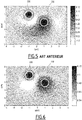
- the reconstruction system 10 and the reconstruction method according to the invention make it possible to more precisely locate absorbers arranged in depth than an imaging system and a reconstruction method of the state of the art, as shown by the Figures 5 and 6 .
- the figure 5 is a view of an image of a medium comprising two absorbers arranged at a depth of 1 cm, and respectively 2 cm, identified by the circles 220, and 230 respectively, reconstructed with an imaging system and a reconstruction method of the state of the art
- the figure 6 is a view of an image of the same medium reconstructed with an imaging system and a reconstruction method according to the invention. Comparing the Figures 5 and 6 those skilled in the art will note that the absorbers are located with a better accuracy in the case of the imaging system and the reconstruction method according to the invention, in particular for the absorber disposed at 2 cm depth.
- the reconstruction of the optical properties using the combination of a plurality of Mellin-Laplace transforms of the magnitude including the elaborate distribution, in particular using the combination of the Mellin-Laplace Y transformed n max + 1s sd (p, n) makes it possible to converge more quickly towards the solution, in order to reduce the processing time required to reconstruct the optical properties of the medium.
- Another advantage of such a combination is that it makes it possible to take into account the scattered photons detected shortly after the light pulse, that is to say up to 1 or 2 ns after the light pulse, also called Prompt photons, using a low-order Mellin Laplace transform, such as n-order values between 0 and 5, while also taking into account so-called delayed photons, ie detected some ns , or more than 5ns, after the light pulse.
- Mellin Laplace transforms of different orders we take into account both the so-called fast photons and the so-called delayed photons, the latter generally coming from deeper depths. It is therefore advantageous to perform the reconstruction using input data combining both Mellin Laplace transforms of different orders.
- input data is meant the observed data, i.e., the terms constituting the vector of the observations Y.
- the reconstruction is carried out according to an iterative method, by performing a measurement B sd (t) for one or different source-detector torque (s).
- the objective is to minimize ⁇ u a ( r , t ) and ⁇ D ( r , t ) .
- B sd (t) is a measurement carried out on the medium to be characterized MC for a given detector source pair sd
- BOY WUT d 1 p , k r ⁇ d r ⁇ + ⁇ ⁇ ⁇ j + k not BOY WUT s 1 p , j r ⁇ . Dd r ⁇ . BOY WUT d 1 p , k r ⁇ d r ⁇
- a time measurement B sd (t) is carried out on the medium to be characterized MC.
- the combination of different Mellin Laplace transforms of a magnitude Y s , d p , not corresponding to a detector source pair, and in particular the use of different values of the order n makes it possible to better take into account the contributions of the fast photons and the delayed photons, the latter coming mainly from higher depths.
Landscapes
- Health & Medical Sciences (AREA)
- Life Sciences & Earth Sciences (AREA)
- Physics & Mathematics (AREA)
- General Health & Medical Sciences (AREA)
- Pathology (AREA)
- Immunology (AREA)
- Chemical & Material Sciences (AREA)
- General Physics & Mathematics (AREA)
- Biochemistry (AREA)
- Analytical Chemistry (AREA)
- Nuclear Medicine, Radiotherapy & Molecular Imaging (AREA)
- Engineering & Computer Science (AREA)
- Animal Behavior & Ethology (AREA)
- Public Health (AREA)
- Veterinary Medicine (AREA)
- Surgery (AREA)
- Molecular Biology (AREA)
- Medical Informatics (AREA)
- Heart & Thoracic Surgery (AREA)
- Biomedical Technology (AREA)
- Biophysics (AREA)
- Optics & Photonics (AREA)
- Chemical Kinetics & Catalysis (AREA)
- Radiology & Medical Imaging (AREA)
- Artificial Intelligence (AREA)
- Computer Vision & Pattern Recognition (AREA)
- Physiology (AREA)
- Psychiatry (AREA)
- Signal Processing (AREA)
- Theoretical Computer Science (AREA)
- Investigating Or Analysing Materials By Optical Means (AREA)
- Investigating, Analyzing Materials By Fluorescence Or Luminescence (AREA)
- Image Generation (AREA)
- Optical Modulation, Optical Deflection, Nonlinear Optics, Optical Demodulation, Optical Logic Elements (AREA)
- Image Analysis (AREA)
Description
La présente invention concerne un procédé de reconstruction de propriétés optiques d'un milieu diffusant à l'aide d'un système de reconstruction comportant au moins une source de rayonnement propre à éclairer un milieu et au moins un détecteur propre à recevoir un signal émis par le milieu, le procédé comprenant:
- l'éclairement du milieu par la ou chaque source de rayonnement,
- la réception, par le ou chaque détecteur, d'un signal émis par le milieu, et
- l'élaboration, pour au moins un couple source-détecteur, d'une première distribution du signal reçu par le détecteur correspondant,
- le calcul de la transformée de Mellin-Laplace, pour un ordre et une variable donnés, d'une grandeur comportant la première distribution, l'ordre étant un nombre entier, la variable étant un nombre réel, et
- la reconstruction de propriétés optiques du milieu à l'aide de la transformée de Mellin-Laplace de ladite grandeur.
- the illumination of the medium by the or each source of radiation,
- receiving, by the or each detector, a signal emitted by the medium, and
- developing, for at least one source-detector pair, a first distribution of the signal received by the corresponding detector,
- calculating the Mellin-Laplace transform, for a given order and variable, of a quantity comprising the first distribution, the order being an integer, the variable being a real number, and
- reconstructing optical properties of the medium using the Mellin-Laplace transform of said magnitude.
L'invention concerne également un tel système de reconstruction.The invention also relates to such a reconstruction system.
L'invention se situe notamment dans le domaine de l'instrumentation médicale, et en particulier dans le domaine de l'imagerie optique de diffusion appliquée à des tissus biologiques.The invention is particularly in the field of medical instrumentation, and in particular in the field of optical diffusion imaging applied to biological tissues.
L'invention s'applique à la détection de différentes pathologies, telles que des cancers du sein, de la prostate ou encore du tube digestif, sein ou cerveau. L'invention s'applique également à la dermatologie, notamment à la caractérisation d'une réaction d'inflammation cutanée.The invention applies to the detection of various pathologies, such as cancers of the breast, the prostate or even the digestive tract, breast or brain. The invention also applies to dermatology, in particular to the characterization of a cutaneous inflammation reaction.
On connaît l'article
Cependant, cet article ne détaille pas précisément comment cette transformée peut être mise en oeuvre dans le cadre de la reconstruction des propriétés optiques d'un milieu diffusant, avec les avantages décrits ci-après.However, this article does not detail how this transform can be implemented in the context of the reconstruction of the optical properties of a diffusing medium, with the advantages described below.
Le but de l'invention est donc de proposer un procédé de reconstruction des propriétés optiques d'un milieu diffusant ainsi qu'un système de reconstruction utilisant avantageusement la transformée de Mellin Laplace, permettant notamment l'accès à des propriétés optiques de diffusion usuellement difficiles à établir, et par exemple la distribution spatiale des coefficients d'absorption ou de diffusion d'un milieu.The aim of the invention is therefore to propose a method for reconstructing the optical properties of a scattering medium as well as a reconstruction system using advantageously the Mellin Laplace transform, in particular allowing access to diffusion optical properties that are usually difficult to establish, and for example the spatial distribution of the absorption or diffusion coefficients of a medium.
A cet effet, l'invention a pour objet un procédé de reconstruction du type précité, caractérisé en ce que l'étape de calcul comporte le calcul d'une pluralité de transformées de Mellin-Laplace de ladite grandeur pour des valeurs distinctes de l'ordre, et en ce que l'étape de reconstruction est effectuée à partir d'une combinaison de la pluralité de transformées de Mellin-Laplace.For this purpose, the subject of the invention is a method of reconstruction of the aforementioned type, characterized in that the calculation step comprises the calculation of a plurality of Mellin-Laplace transforms of said magnitude for values distinct from the order, and in that the reconstruction step is performed from a combination of the plurality of Mellin-Laplace transforms.
Par reconstruction des propriétés optiques, on entend par exemple :
- la reconstruction des propriétés d'absorption, ces dernières étant notamment caractérisées par le coefficient d'absorption, noté µa,
- la reconstruction des propriétés de diffusion, ces dernières étant notamment caractérisées par le coefficient de diffusion réduit µ's ou par le coefficient de diffusion D, et
- la reconstruction des propriétés de fluorescence, ces dernières étant notamment caractérisées par une fonction de réponse (F) d'un fluorophore, ou par une concentration c d'un fluorophore, ou encore par toute autre grandeur exprimant une quantité q d'un fluorophore, ce dernier étant par exemple endogène ou exogène.
- the reconstruction of the absorption properties, the latter being characterized in particular by the absorption coefficient, denoted μ a ,
- the reconstruction of the diffusion properties, the latter being characterized in particular by the reduced diffusion coefficient μ ' s or by the diffusion coefficient D, and
- the reconstruction of the fluorescence properties, the latter being characterized in particular by a response function (F) of a fluorophore, or by a concentration c of a fluorophore, or by any other quantity expressing a quantity q of a fluorophore, the latter being for example endogenous or exogenous.
Suivant d'autres aspects avantageux de l'invention, le procédé de reconstruction comporte une ou plusieurs des caractéristiques suivantes, prises isolément ou suivant toutes les combinaisons techniquement possibles :
- l'étape de calcul comporte le calcul d'au moins une transformée de Mellin-Laplace de ladite grandeur pour une valeur de l'ordre supérieure ou égale à 5, de préférence supérieure ou égale à 8,
- l'étape de calcul comporte le calcul de nmax+1 transformées de Mellin-Laplace, l'ordre prenant successivement toutes les valeurs comprises entre 0 et nmax, avec nmax supérieur ou égal à 5, de préférence supérieur ou égal à 8,
- la valeur de la variable est comprise entre 1 ns-1 et 20 ns-1,
- le procédé comprend en outre :
- + la détermination, pour au moins un couple source-détecteur, d'une première fonction de modélisation d'un signal de diffusion de la lumière entre la source et le détecteur dans le milieu,
- + l'élaboration, pour ledit au moins un couple source-détecteur, d'une deuxième distribution d'un signal reçu par le détecteur pour un milieu de référence, le signal reçu étant émis par le milieu de référence suite à l'éclairement dudit milieu par la source, et
- + la détermination, pour ledit au moins un couple source-détecteur, d'une deuxième fonction de modélisation d'un signal de diffusion de la lumière entre la source et le détecteur dans le milieu de référence,
- et dans lequel ladite grandeur dépend de la première distribution, de la première fonction de modélisation, de la deuxième distribution et de la deuxième fonction de modélisation,
- ladite grandeur est obtenue par soustraction du produit de la deuxième distribution et de la première fonction de modélisation du produit de la première distribution et de la deuxième fonction de modélisation,
- ladite grandeur est le ratio entre le produit de la première distribution et de la deuxième fonction de modélisation et le produit de la deuxième distribution et de la première fonction de modélisation,
- la ou chaque source de rayonnement comporte une source de lumière puisée,
- le ou chaque détecteur est un détecteur résolu en temps, et
- les propriétés optiques comprennent au moins un élément parmi le groupe consistant en :
- + les propriétés d'absorption de la lumière, caractérisées notamment par le coefficient d'absorption,
- + les propriétés de diffusion, caractérisées notamment par le coefficient de diffusion réduit ou par le coefficient de diffusion, et
- + les propriétés de fluorescence, caractérisées notamment par une fonction de réponse d'un fluorophore, ou par une concentration du fluorophore, ou encore par une grandeur fonction d'une quantité du fluorophore.
- L'invention a également pour objet un système de reconstruction comprenant
- au moins une source de rayonnement propre à éclairer le milieu,
- au moins un détecteur propre à recevoir un signal émis par le milieu,
- des moyens d'élaboration, pour au moins un couple source-détecteur, d'une distribution du signal reçu par le détecteur correspondant,
- des moyens de calcul de la transformée de Mellin-Laplace, pour un ordre et une variable donnés, d'une grandeur comportant la distribution, l'ordre étant un nombre entier, la variable étant un nombre réel, et
- des moyens de reconstruction de propriétés optiques du milieu à l'aide de la transformée de Mellin-Laplace de ladite grandeur,
- the calculation step comprises calculating at least one Mellin-Laplace transform of said quantity for a value of the order greater than or equal to 5, preferably greater than or equal to 8,
- the calculation step comprises the calculation of n max +1 transformed Mellin-Laplace, the order taking successively all values between 0 and n max , with n max greater than or equal to 5, preferably greater than or equal to 8 ,
- the value of the variable is between 1 ns -1 and 20 ns -1 ,
- the method further comprises:
- + the determination, for at least one source-detector pair, of a first modeling function of a light scattering signal between the source and the detector in the medium,
- + developing, for said at least one source-detector pair, a second distribution of a signal received by the detector for a reference medium, the received signal being emitted by the reference medium following the illumination of said medium by source, and
- + the determination, for said at least one source-detector pair, of a second modeling function of a light scattering signal between the source and the detector in the reference medium,
- and wherein said magnitude depends on the first distribution, the first modeling function, the second distribution and the second modeling function,
- said magnitude is obtained by subtracting the product of the second distribution and the first product modeling function of the first distribution and the second modeling function,
- said quantity is the ratio between the product of the first distribution and the second modeling function and the product of the second distribution and the first modeling function,
- the or each radiation source comprises a pulsed light source,
- the or each detector is a time-resolved detector, and
- the optical properties comprise at least one of the group consisting of:
- + the absorption properties of light, characterized in particular by the absorption coefficient,
- + the diffusion properties, characterized in particular by the reduced diffusion coefficient or by the diffusion coefficient, and
- + the fluorescence properties, characterized in particular by a response function of a fluorophore, or by a concentration of the fluorophore, or by a quantity depending on an amount of the fluorophore.
- The subject of the invention is also a reconstruction system comprising
- at least one source of radiation suitable for illuminating the medium,
- at least one detector capable of receiving a signal emitted by the medium,
- means for generating, for at least one source-detector pair, a distribution of the signal received by the corresponding detector,
- means for calculating the Mellin-Laplace transform, for a given order and variable, of a quantity comprising the distribution, the order being an integer, the variable being a real number, and
- means for reconstructing optical properties of the medium using the Mellin-Laplace transform of said magnitude,
Suivant un autre aspect avantageux de l'invention, le système de reconstruction comprend en outre des moyens de calcul propres à calculer au moins une transformée de Mellin-Laplace de ladite grandeur pour une valeur de l'ordre supérieure ou égale à 5, de préférence supérieure ou égale à 8.According to another advantageous aspect of the invention, the reconstruction system further comprises calculation means capable of calculating at least one Mellin-Laplace transform of said quantity for a value of the order greater than or equal to 5, preferably greater than or equal to 8.
Ces caractéristiques et avantages de l'invention apparaîtront à la lecture de la description qui va suivre, donnée uniquement à titre d'exemple, et faite en référence aux dessins annexés sur lesquels :
- la
figure 1 est une représentation schématique d'un système de reconstruction selon l'invention, propre à reconstruire une image d'un milieu, - la
figure 2 est un ensemble de courbes représentant une distribution temporelle d'un signal reçu par le système de lafigure 1 et les transformées de Mellin-Laplace de cette distribution temporelle calculées pour des valeurs d'ordre comprisesentre 0 et 9, - la
figure 3 est un organigramme d'un procédé de reconstruction selon l'invention, - la
figure 4 est un ensemble d'images représentant des cartes de sensibilité pour les transformées de Mellin-Laplace calculées, chaque image correspondant à une valeur d'ordre respective et compriseentre 0 et 8, - la
figure 5 est une vue d'une image du milieu reconstruite avec un système de reconstruction et un procédé de reconstruction de l'état de la technique, et - la
figure 6 est une vue analogue à celle de lafigure 5 avec un système de reconstruction et un procédé de reconstruction selon l'invention.
- the
figure 1 is a schematic representation of a reconstruction system according to the invention, suitable for reconstructing an image of a medium, - the
figure 2 is a set of curves representing a temporal distribution of a signal received by the system of thefigure 1 and the Mellin-Laplace transforms of this temporal distribution calculated for order values between 0 and 9, - the
figure 3 is a flowchart of a reconstruction method according to the invention, - the
figure 4 is a set of images representing sensitivity maps for calculated Mellin-Laplace transforms, each image corresponding to a respective order value and ranging from 0 to 8, - the
figure 5 is a view of an image of the reconstructed medium with a reconstruction system and a reconstruction method of the state of the art, and - the
figure 6 is a view similar to that of thefigure 5 with a reconstruction system and a reconstruction method according to the invention.
Sur la
Le système de reconstruction 10 comprend une pluralité de sources de rayonnement 14 aptes à éclairer le milieu 12 et une pluralité de détecteurs 16 propres à recevoir un signal émis par le milieu 12. Les sources de rayonnement 14 et les détecteurs 16, sont, par exemple, agencés dans une sonde, non représentée.The
Le système 10 comprend une unité de traitement d'informations 18 et un écran 20 d'affichage d'une image du milieu.The
Dans le mode de réalisation décrit, le système 10 est un système temporel, et chaque source de rayonnement 14 est une source de rayonnement puisée. Chaque détecteur 16 est un détecteur résolu en temps, c'est-à-dire un détecteur permettant de mesurer la distribution temporelle du temps d'arrivée des photons, également appelés TCSPC (de l'anglais Time-Correlated Single Photon Counting). In the embodiment described, the
Selon l'exemple représenté, le milieu 12 présente une surface d'observation 22, en forme d'un plan parallèle à un axe longitudinal X et un axe transversal Y, et au contact de laquelle les sources 14 et les détecteurs 16 sont propres à être appliqués. Le milieu 12 présente une direction d'observation 24 s'étendant selon un axe vertical Z et sensiblement perpendiculairement à la surface d'observation 22.According to the example shown, the medium 12 has an observation surface 22, in the form of a plane parallel to a longitudinal axis X and a transverse axis Y, and in contact with which the
Dans l'exemple de réalisation de la
Le milieu à caractériser MC est un milieu diffusant contenant des inclusions dont les propriétés optiques d'absorption ou de diffusion sont différentes de celles du milieu. 26, Une seule inclusion 26 est représentée sur la
Chaque source de rayonnement pulsée 14 comporte une source lumineuse pulsée 28 et une fibre optique d'excitation 30 reliée à la source pulsée 28 pour la transmission de l'impulsion lumineuse jusqu'au milieu 12. Lorsqu'une telle source fibrée est utilisée, on assimile l'extrémité libre de la fibre d'excitation 30 à la source s.Each source of
En variante non représentée, chaque source de rayonnement pulsée 14 comporte une fibre optique d'excitation 30 reliée à une unique source lumineuse pulsée commune à la pluralité de sources de rayonnement 14. Selon cette variante, le système 10 comprend en outre un commutateur optique ou un multiplexeur pour sélectionner la fibre d'excitation 30 dans laquelle le faisceau lumineux est envoyé.In a variant not shown, each source of
En variante encore, l'ensemble des sources de rayonnement pulsée 14 est formé d'une unique source lumineuse pulsée et d'un dispositif à miroir de type MEMS (de l'anglais MicroElectroMechanical Systems), non représenté, pour balayer le milieu 12 avec la lumière issue de la source lumineuse puisée. En variante encore, la source 14 est une source multiplexée, délivrant des impulsions lumineuses à différentes longueur d'onde.As a further variant, the set of sources of
Dans le cas d'un examen de la surface 22 du milieu ou d'un examen à une faible profondeur du milieu 12, c'est-à-dire une profondeur de quelques millimètres à quelques centimètres, la longueur d'ondes de chaque source de rayonnement pulsée 14 est, de préférence, dans le domaine du visible ou du proche infrarouge, c'est-à-dire comprise entre 500 nm et 1300 nm. Le taux de répétition est d'environ 50 MHz, et en général compris entre 10 MHz et 100 MHz.In the case of an examination of the surface 22 of the medium or of an examination at a shallow depth of the medium 12, that is to say a depth of a few millimeters to a few centimeters, the wavelength of each source pulsed
Les impulsions émises par chaque source de rayonnement pulsée 14 présentent une durée comprise entre 10 picosecondes et 1 nanoseconde, de préférence comprise 10 picosecondes et 100 picosecondes, chaque source lumineuse pulsée 28 étant propre à générer une impulsion de largeur temporelle de durée comprise entre 10 picosecondes et 1 nanoseconde, de préférence comprise 10 picosecondes et 100 picosecondes.The pulses emitted by each
Chaque détecteur résolu en temps 16, noté également d, comporte une fibre optique de détection 32 reliée à un module de détection résolu en temps 34. Lorsqu'un tel détecteur fibré est utilisé, l'extrémité libre de cette fibre optique de détection 32 est assimilée au détecteur d.Each time-resolved
Dans l'exemple de réalisation de la
L'organe de détection 36 est, par exemple, un photomultiplicateur, ou une photodiode à avalanche, également appelée APD (de l'anglais Avalanche Photodiode), ou une photodiode à avalanche à photon unique, également SPAD (de l'anglais Single-Photon Avalanche Diode) ou encore un tube intensificateur d'images ayant une ou plusieurs anodes (de l'anglais Multi-Channel Plate). The
La sonde est, dans cet exemple, une sonde compacte pour le diagnostic de certains cancers, tels qu'une sonde portative pour le diagnostic du cancer du sein, une sonde endorectale pour le diagnostic du cancer de la prostate, ou encore une sonde de dermatologie. En variante, la sonde est une sonde d'endoscope telle qu'une sonde souple pour le diagnostic du cancer digestif. En variante, la sonde est un dispositif applicable à d'autres organes.The probe is, in this example, a compact probe for the diagnosis of certain cancers, such as a portable probe for the diagnosis of breast cancer, an endorectal probe for the diagnosis of prostate cancer, or a dermatology probe. . Alternatively, the probe is an endoscope probe such as a flexible probe for the diagnosis of digestive cancer. Alternatively, the probe is a device applicable to other organs.
L'unité de traitement de l'information 18 comporte un processeur de données 38 et une mémoire 40 associée au processeur 38.The
L'unité de traitement 18 comporte des moyens 42 d'élaboration, pour au moins un couple source 14 - détecteur 16, d'une première distribution Bsd d'un signal reçu par le détecteur 16 correspondant pour le milieu à caractériser MC, le signal reçu étant émis par le milieu diffusant à caractériser MC suite à l'éclairement dudit milieu MC par la source 14 correspondante. La source 14, et respectivement le détecteur 16, correspondants sont repérés par les indices s, et respectivement d.The
Dans le mode de réalisation décrit, la première distribution est une distribution temporelle respectivement notée Bsd(t). Les moyens d'élaboration 42 sont, de préférence, réalisés sous forme d'une ou plusieurs cartes électroniques connectées au détecteur 16 et permettant de mesurer la distribution temporelle du temps d'arrivée des photons.In the embodiment described, the first distribution is a time distribution respectively denoted B sd (t). The production means 42 are preferably made in the form of one or more electronic boards connected to the
Chaque source de lumière pulsée 28 comporte un laser impulsionnel. En variante, chaque source lumineuse pulsée 28 comporte une diode laser. En variante encore, chaque source lumineuse pulsée 28 comporte une source de lumière constante dont l'intensité lumineuse est modulée en des impulsions de durée équivalente par un dispositif à obturation rapide. Ainsi, la source est apte à émettre un rayonnement lumineux prenant la forme d'une impulsion temporelle.Each pulsed
Selon ce mode particulier, l'extrémité de chaque fibre d'excitation 30 s'étend perpendiculairement à la surface d'observation 22 c'est-à-dire selon l'axe Z, ou encore de manière oblique par rapport à l'axe Z afin d'émettre la lumière en biais par rapport à la surface d'observation 22.According to this particular embodiment, the end of each
La mémoire 40 est apte à stocker un logiciel 44 de calcul d'une pluralité de transformées de Mellin-Laplace Ysd (p,n), pour une variable p, également appelée largeur, et des valeurs distinctes d'un ordre n donnés, d'une grandeur Ysd(t) comportant la première distribution Bsd(t), l'ordre n étant un nombre entier et la variable p étant un nombre réel.The
La transformée de Mellin-Laplace d'ordre n et de largeur p d'une fonction f est notée f(p,n), et vérifie l'équation suivante : ![]()
![]()
La transformée de Mellin-Laplace f(p,n) de la fonction f s'écrit également : ![]()
![]()
![]()
![]()
Sur la
De manière générale, la transformée de Mellin-Laplace f(p,n) d''ordre n et de largeur p de la fonction f sera considérée comme toute fonction comprenant le terme 
Dans le mode de réalisation décrit, au moins une transformée de Mellin-Laplace Ysd (p,n) est calculée pour une valeur de l'ordre n supérieure ou égale à 5, de préférence supérieure ou égale à 8.In the embodiment described, at least one Mellin-Laplace transform Y sd (p, n) is calculated for a value of order n greater than or equal to 5, preferably greater than or equal to 8.
Dans le mode de réalisation décrit, l'ordre n présente une valeur comprise entre 0 et une valeur maximale nmax. L'ordre n prend, par exemple, successivement toutes les valeurs comprises entre 0 et nmax. Autrement dit, nmax+1 transformées de Mellin-Laplace Ysd (p,n) sont alors calculées par le logiciel de calcul 44. La valeur maximale nmax est supérieure ou égale à 5, de préférence supérieure ou égale à 8.In the embodiment described, the order n has a value between 0 and a maximum value n max . The order n takes, for example, successively all values between 0 and n max . In other words, n max +1 Mellin-Laplace transforms Y sd (p, n) are then calculated by the
La combinaison de transformées de Laplace d'ordre différents, et notamment des faibles ordres, c'est-à-dire n proche de 0, avec des ordres importants, c'est-à-dire n ≥ 5, permet la prise en compte de la contribution, au signal détecté, de photons émis à des instants très proches après l'impulsion d'excitation (ordres faibles) ainsi qu'à des instants plus éloignés (ordres importants), ces derniers étant appelés photons retardés, car ils sont détectés quelques ns après l'impulsion lumineuse d'excitation.The combination of Laplace transforms of different order, and in particular weak orders, that is to say n close to 0, with large orders, that is to say n ≥ 5, makes it possible to take into account of the contribution, to the detected signal, of photons emitted at very close moments after the excitation pulse (weak orders) as well as at more distant times (important orders), the latter being called delayed photons, because they are detected a few ns after the excitation light pulse.
Dans le mode de réalisation décrit, la valeur de la largeur p est comprise entre 1 ns-1 et 20 ns-1, où ns est le symbole de la nanoseconde.
La mémoire 40 est également apte à stocker un logiciel 46 de reconstruction de propriétés optiques du milieu 12 à partir d'une combinaison de la pluralité de transformées de Mellin-Laplace Ysd (p,n) de ladite grandeur Ysd (t). Le logiciel de reconstruction 46 est propre à reconstruire de la distribution spatiale de coefficients optiques, tels que le coefficient d'absorption optique µa ou le coefficient de diffusion D. En variante, le logiciel de reconstruction 46 est propre à reconstruire une carte de fluorescence du milieu 12.In the embodiment described, the value of the width p is between 1 ns -1 and 20 ns -1 , where ns is the symbol of the nanosecond.
The
Dans le mode de réalisation décrit, la grandeur Ysd(t) est un signal corrigé permettant de prendre en compte la réponse instrument, également appelé distribution corrigée, et est décrite plus en détail ci-après.In the embodiment described, the quantity Y sd (t) is a corrected signal making it possible to take into account the instrument response, also called the corrected distribution, and is described in more detail below.
En variante, la grandeur sur laquelle est calculée la pluralité de transformées de Mellin-Laplace est la première distribution Bsd(t).Alternatively, the magnitude on which the plurality of Mellin-Laplace transforms is calculated is the first distribution B sd (t).
En variante, les moyens de calcul 44 et les moyens de reconstruction 46 sont réalisés sous forme de composants logiques programmables ou encore sous forme de circuits intégrés dédiés.As a variant, the calculation means 44 and the reconstruction means 46 are made in the form of programmable logic components or in the form of dedicated integrated circuits.
Le fonctionnement du système d'imagerie 10 selon l'invention est décrit ci-après à l'aide de la
Lors de l'étape 100, le milieu à caractériser MC est éclairé par la ou les sources 14 correspondantes. En cas d'une pluralité de sources 14, l'éclairement du milieu 12 est effectué successivement pour chacune des sources 14. Lorsqu'il est éclairé, le milieu à caractériser MC émet en retour un signal optique de diffusion, susceptible d'être détecté par le ou chaque détecteur 16, et la première distribution du signal reçu Bsd(t) est élaborée, lors de l'étape 110, pour chaque couple source 14 - détecteur 16, également noté (s, d), à l'aide des moyens d'élaboration 42.During
La première distribution temporelle Bsd(t) vérifie l'équation suivante : ![]()
- où IRFsd(t) représente la réponse instrument, c'est-à-dire l'influence de la source s et du détecteur d sur la première distribution élaborée, et
- Gsd(t) représente une première fonction de modélisation d'un signal de diffusion de la lumière entre la
source 14 et le détecteur 16 dans le milieu à caractériser MC.
- where IRF sd (t) represents the instrument response, that is to say the influence of the source s and the detector d on the first developed distribution, and
- G sd (t) represents a first modeling function of a light scattering signal between the
source 14 and thedetector 16 in the medium to be characterized MC.
On note Ss(t) la réponse temporelle de la source 14, également notée s. Dans cet exemple, la source 14 est une brève impulsion lumineuse, souvent modélisée par une distribution de type Dirac ponctuelle. Ss(t) représente l'intensité temporelle du signal émis. Lorsque la source 14 est fibrée (source de lumière couplée à une fibre optique), c'est l'extrémité de la fibre optique d'excitation 30, qui est alors considérée comme la source, comme précédemment indiqué.We denote by S s (t) the temporal response of the
On note Dd(t) la réponse temporelle du détecteur 16, également noté d. Cette réponse traduit notamment le délai entre l'arrivée d'un photon sur le détecteur 16 et sa détection effective. Lorsque le détecteur 16 est fibré (détecteur couplé à une fibre optique), c'est l'extrémité de la fibre de détection 32, qui est considérée comme le détecteur, comme précédemment indiqué.D d (t) is the time response of
On estime généralement la réponse instrument, notée IRFsd(t) l'indice sd corrrespondant à un couple source d'excitation s et détecteur d. Cette réponse instrument est obtenue en combinant Ss(t) et Dd(t) suivant : IRFsd(t) = Ss(t)*Dd(t), où * désigne le produit de convolution.The instrument response, denoted IRF sd (t), is generally considered to be the index sd corresponding to a source pair of excitation s and detector d. This instrument response is obtained by combining Ss (t) and Dd (t) according to: IRF sd (t) = S s (t) * D d (t), where * denotes the convolution product.
Lorsqu'on a plusieurs sources et plusieurs détecteurs, on détermine IRFsd(t) pour chaque couple source-détecteur, car chaque source et chaque détecteur a sa propre réponse. En pratique, cela se fait en plaçant une source (ou une extrémité de fibre optique constituant la source) en face d'un détecteur (ou d'une extrémité de fibre optique constituant le détecteur). Cela suppose un alignement soigné entre la source et le détecteur, et cela prend du temps, notamment lorsqu'on augmente le nombre de sources et de détecteurs. A titre d'exemple, 100 fonctions de réponse instrument IRFsd sont à déterminer lorsqu'on dispose de 10 sources et 10 détecteurs.When there are multiple sources and detectors, IRF sd (t) is determined for each source-detector pair because each source and detector has its own response. In practice, this is done by placing a source (or an optical fiber end constituting the source) in front of a detector (or an optical fiber end constituting the detector). This presupposes a careful alignment between the source and the detector, and this takes time, especially when increasing the number of sources and detectors. By way of example, 100 IRF instrument response functions sd are to be determined when 10 sources and 10 detectors are available.
Lors de l'étape 120, la réponse instrument IRFsd(t) est prise en compte à l'aide d'une deuxième distribution temporelle Asd(t) et d'une deuxième fonction de modélisation Gsd 0(t). La deuxième distribution temporelle Asd(t) est élaborée pour un milieu de référence MR et dans les mêmes conditions expérimentales que pour la première distribution temporelle Bsd(t).In
Le milieu de référence MR, également appelé fantôme, est connu en soi et est, par exemple, décrit dans le document
L'élaboration de la deuxième distribution temporelle Asd(t) est de préférence effectuée de manière préliminaire, avant l'étape 100, et le milieu de référence MR est alors remplacé par le milieu à caractériser MC au début de l'étape 100.The development of the second temporal distribution A sd (t) is preferably carried out in a preliminary manner, before
En variante, l'élaboration de la deuxième distribution temporelle Asd(t) est effectuée lors de l'étape 120, ce qui nécessite de changer le milieu 12, et de remplacer le milieu à caractériser MC par le milieu de référence MR.Alternatively, the development of the second temporal distribution A sd (t) is performed during
La deuxième distribution temporelle Asd(t) vérifie alors l'équation suivante : ![]()
![]()
Les première et deuxième fonctions de modélisation Gsd(t), Gsd 0(t) sont, par exemple, des fonctions de Green, bien connues dans le domaine la diffusion optique. Chaque fonction de Green Gsd(t), Gsd 0(t) représente la densité de photons au niveau du détecteur 16 lorsque le milieu 12, c'est-à-dire le milieu de référence MR pour la première fonction de modélisation et respectivement le milieu à caractériser MC pour la deuxième fonction de modélisation, est éclairé par la source 14, où s et d sont les indices désignant respectivement la source 14 et le détecteur 16.The first and second modeling functions G sd (t), G sd 0 (t) are, for example, Green functions, well known in the field of optical diffusion. Each Green G function sd (t), G sd 0 (t) represents the photon density at the
Le signal corrigé Ysd(t) est alors calculé en fonction de la première distribution Bsd(t), de la première fonction de modélisation Gsd(t), de la deuxième distribution Asd(t) et de la deuxième fonction de modélisation Gsd 0(t).The corrected signal Y sd (t) is then calculated as a function of the first distribution B sd (t), of the first modeling function G sd (t), of the second distribution A sd (t) and of the second function of modeling G sd 0 (t).
Le signal corrigé Ysd(t) est le résultat d'une opération de comparaison du produit de la deuxième distribution Asd et de la première fonction de modélisation Gsd avec le produit de la première distribution Bsd et de la deuxième fonction de modélisation Gsd 0. L'opération de comparaison comporte une opération arithmétique du produit de la deuxième distribution Asd et de la première fonction de modélisation Gsd avec le produit de la première distribution Bsd et de la deuxième fonction de modélisation Gsd 0.The corrected signal Y sd (t) is the result of a comparison operation of the product of the second distribution A sd and the first modeling function G sd with the product of the first distribution B sd and the second modeling function G sd 0 . The comparison operation comprises an arithmetic operation of the product of the second distribution A sd and the first modeling function G sd with the product of the first distribution B sd and the second modeling function G sd 0 .
L'opération arithmétique est, par exemple, une soustraction du produit de la deuxième distribution Asd et de la première fonction de modélisation Gsd du produit de la première distribution Bsd et de la deuxième fonction de modélisation Gsd 0.The arithmetic operation is, for example, a subtraction of the product of the second distribution A sd and the first modeling function G sd of the product of the first distribution B sd and the second modeling function G sd 0 .
Dans le mode de réalisation décrit, le produit de la deuxième distribution Asd(t) et de la première fonction de modélisation Gsd(t) et le produit de la première distribution Bsd(t) et de la deuxième fonction de modélisation Gsd 0(t) sont des produits de convolution, les première Bsd(t) et deuxième Asd(t) distributions étant des distributions temporelles.In the embodiment described, the product of the second distribution A sd (t) and the first modeling function G sd (t) and the product of the first distribution B sd (t) and the second modeling function G sd 0 (t) are convolution products, the first B sd (t) and second A sd (t) distributions being temporal distributions.
Le signal corrigé Ysd(t) vérifie l'équation suivante : ![]()
![]()
En variante, l'opération arithmétique est un ratio entre le produit de la première distribution temporelle Bsd(t) et de la deuxième fonction de modélisation Gsd 0(t) et le produit de la deuxième distribution temporelle Asd(t) et de la première fonction de modélisation Gsd(t).As a variant, the arithmetic operation is a ratio between the product of the first time distribution B sd (t) and the second modeling function G sd 0 (t) and the product of the second time distribution A sd (t) and of the first modeling function G sd (t).
Selon cette variante, le signal corrigé Ysd(t) vérifie alors l'équation suivante : ![]()
![]()
En complément, la première fonction de modélisation Gsd(t) est déterminée de manière approchée à l'aide de la fonction de Green Gsd 1(t) pour le milieu à caractériser MC, et on obtient alors les équations suivantes : 
- où µa et D représentent respectivement le coefficient d'absorption et le coefficient de diffusion du milieu à caractériser MC.
- IRFsd(t) représente la réponse instrument,
- Gs(r,t) = G(rs,r,t) est la fonction de Green représentant la densité de photons à un endroit r du milieu MC lorsque le milieu MC est éclairé par la source s située en rs,
- Gd(r,t) = G(rd,r,t) est la fonction de Green représentant la densité de photons à l'endroit r du milieu MC lorsque le milieu à caractériser MC est éclairé par la source s située en rd. On écrit également Gd(r,t) = G(r,rd,t). Ainsi, cette fonction de Green représente également la densité de photons au niveau du détecteur (rd) lorsque le milieu à caractériser MC est éclairé par une source située en r.
- where μ a and D respectively represent the absorption coefficient and the diffusion coefficient of the medium to be characterized MC.
- IRF sd (t) represents the instrument response,
- G s (r, t) = G (r s , r, t) is the Green function representing the density of photons at a location r of the medium MC when the medium MC is illuminated by the source s located in r s ,
- G d (r, t) = G (r d , r, t) is the Green function representing the density of photons at the location r of the medium MC when the medium to be characterized MC is illuminated by the source s situated in r d . We also write G d (r, t) = G (r, r d , t). So, this function of Green also represents the photon density at the detector (r d ) when the medium to be characterized MC is illuminated by a source located in r.
Autrement dit, Gsd(t) correspond aux vraies valeurs µa(r, t) et D(r, t), c'est-à-dire aux valeurs recherchées, et Gsd 1(t) correspond à des valeurs approchées µ1 a(r, t) et D1(r, t), avec µa(r, t) = µ1 a(r, t) + δµa(r, t) et D(r, t) = D1(r, t) + δD(r, t). Le processus de reconstruction des propriétés optiques est généralement itératif, de telle sorte qu'au cours de chaque itération, on obtient des valeurs µ1 a(r) et D1(r), auxquelles correspondent des fonctions de Green ![]()
![]()
Les coefficients µa et D sont constants dans le temps, et les valeurs µa(r, t) = µa(r)∂(t) et D(r,t) = D(r)∂(t), ∂(t) représentent une distribution de Dirac à l'instant t.The coefficients μ a and D are constant in time, and the values μ a (r, t) = μ a (r) ∂ (t) and D (r, t) = D (r) ∂ (t), ∂ (t) represent a distribution of Dirac at time t.
Le calcul du signal corrigé Ysd(t), également appelé distribution temporelle corrigée, s'affranchit donc de la connaissance précise de la réponse instrument IRFsd(t) d'après les équations (6), (7) ou encore (8). Ceci permet d'éviter des mesures expérimentales relativement longues et fastidieuses afin de déterminer la réponse instrument du système d'imagerie 10.The computation of the corrected signal Y sd (t), also called corrected temporal distribution, is thus freed from the precise knowledge of the IRF instrument response sd (t) according to equations (6), (7) or again (8). ). This makes it possible to avoid relatively long and tedious experimental measurements in order to determine the instrument response of the
En variante, la réponse instrument IRFsd(t), représentant la répartition temporelle de l'impulsion générée par la source de rayonnement et détectée par le détecteur en l'absence de milieu diffusant, est mesurée, pour chaque couple source-détecteur (s, d), lors d'une opération de calibrage au cours de laquelle la source s est placée face au détecteur d en l'absence du milieu 12.As a variant, the IRF instrument response sd (t), representing the time distribution of the pulse generated by the radiation source and detected by the detector in the absence of scattering medium, is measured for each source-detector pair (s). , d), during a calibration operation during which the source s is placed facing the detector d in the absence of the medium 12.
Lors de l'étape 130, les transformées de Mellin-Laplace Ysd (p,n) de la distribution corrigée sont alors calculées pour différentes valeurs de l'ordre n comprises entre 0 et nmax, de préférence pour toutes les valeurs successives comprises entre 0 et nmax, suivant l'équation suivante : ![]()
![]()
Or, la distribution corrigée Ysd(t) vérifie l'équation suivante : ![]()
![]()
Les équations (9) et (10) permettent alors d'obtenir l'équation suivante, étant donné que la transformée de Mellin-Laplace d'un produit de convolution de deux termes est égale au produit des transformées de Mellin-Laplace de chacun de ces deux termes : ![]()
![]()
L'équation (11) permet ainsi de calculer la transformée de Mellin-Laplace à l'ordre n de la distribution corrigée Ysd (p,n) des transformées de Mellin-Laplace de la deuxième distribution temporelle Asd(t) et des fonctions de Green Gs 1(r), Gd 1(r) approchant la première fonction de modélisation Gsd(t).Equation (11) thus makes it possible to calculate the Mellin-Laplace transform at the order n of the corrected distribution Y sd (p, n) of the Mellin-Laplace transforms of the second temporal distribution A sd (t) and the functions of Green G s 1 (r), G d 1 (r) approaching the first modeling function G sd (t).
Le milieu 12 est discrétisé en une pluralité M de voxels référencés m, avec m compris entre 1 et M, afin de calculer les transformées de Mellin-Laplace des fonctions de Green Gs 1(r), Gd 1(r). Les fonctions de Green Gs 1(r), Gd 1(r) discrétisées pour chaque voxel m sont notées Gs 1(rm), Gd 1(rm).The medium 12 is discretized into a plurality M of voxels referenced m, with m lying between 1 and M, in order to calculate the Mellin-Laplace transforms of the functions of Green G s 1 (r), G d 1 (r). The functions of Green G s 1 (r), G d 1 (r) discretized for each voxel m are denoted G s 1 (r m ), G d 1 (r m ).
Selon la variante dans laquelle la réponse instrument IRFsd(t) est mesurée pour chaque couple source-détecteur (s, d), lors d'une opération de calibrage, les transformées de Mellin-Laplace de la première distribution Bsd (p,n) et de la réponse instrument IRFsd (p,n) sont calculées pour différentes valeurs de l'ordre n comprises entre 0 et nmax, de préférence pour toutes les valeurs successives comprises entre 0 et nmax.According to the variant in which the IRF instrument response sd (t) is measured for each source-detector pair (s, d), during a calibration operation, the Mellin-Laplace transforms of the first distribution B sd (p, n) and the IRF instrument response sd (p, n) are calculated for different values of the order n between 0 and n max , preferably for all the successive values between 0 and n max .
La reconstruction de propriétés optiques du milieu 12 est alors effectuée lors de l'étape 140, afin de déterminer par exemple les vecteurs
L'étape de reconstruction vise alors à résoudre le système matriciel suivant : ![]()
![]()
Le vecteur des observations Y contient les Nn transformées de Mellin-Laplace de la distribution corrigée Ysd (p,n), avec Nn égal à nmax+1, calculées pour toutes les valeurs successives de l'ordre n comprises entre 0 et nmax et pour les couples source-détecteur (s, d) considérés.The observation vector Y contains the Mellin-Laplace transformed Nn of the corrected distribution Y sd (p, n) , with Nn equal to n max +1, calculated for all the successive values of the order n between 0 and n max and for the source-detector pairs (s, d) considered.
On définit, pour chaque triplet (s, d, n) des indices s, d et de l'ordre n, un indice I de la manière suivante : ![]()
![]()
La valeur maximale de l'indice I est égale à Imax, tel que : ![]()
![]()
Le vecteur des observations Y comporte alors Imax lignes.The vector of the observations Y then comprises Imax lines.
La matrice de passage W comprend une première partie Wµ comportant des premiers termes notés Wµ (I, m) et une deuxième partie WD comportant des deuxièmes termes notés WD (I,m). Cette matrice est appelée matrice de sensibilité des mesures Y aux propriétés optiques X.The passage matrix W comprises a first part W μ comprising first terms denoted W μ ( I , m ) and a second part W D having second terms denoted W D ( I , m ). This matrix is called sensitivity matrix of Y measurements with X optical properties.
Les premiers termes Wµ (I,m) vérifient l'équation suivante : ![]()
![]()
![]()
![]()
Selon ce mode de réalisation, au cours de chaque itération, les transformées de Mellin Laplace, de différents ordres, de Gs 1(t) et de Gd 1(t) sont déterminées, notamment en utilisant l'expression suivante : 
![]()
![]()
La matrice de passage W comporte alors Imax lignes et 2M colonnes.The matrix of passage W then comprises Imax lines and 2M columns.
Chaque terme Wµ (I,m), WD (I,m) de la matrice de passage W est déterminé par modélisation, à chaque itération, en fonction des propriétés optiques déterminées lors de l'itération précédente, ou lors de la première itération, en fonction de propriétés optiques initialisées par l'opérateur. Cette initialisation est réalisée en considérant par exemple un milieu 12 homogène.Each term W μ ( I , m ), W D ( I , m ) of the transition matrix W is determined by modeling, at each iteration, as a function of the optical properties determined during the previous iteration, or during the first iteration, according to optical properties initialized by the operator. This initialization is performed considering, for example, a
Le vecteur des inconnues X comporte 2M lignes et une colonne, et contient les inconnues µa(m) et D(m) pour chacun des M voxels. Les M premières lignes correspondent aux inconnues µa(m) et les M lignes suivantes du vecteur X correspondent aux inconnues D(m).The vector of the unknowns X has 2M lines and a column, and contains the unknowns μ a (m) and D (m) for each of the M voxels. The first M lines correspond to the unknowns μ a (m) and the following M lines of the vector X correspond to the unknowns D (m).
L'inversion de la matrice de passage W est réalisée selon des algorithmes d'inversion bien connus de l'homme du métier, tels qu'un algorithme de descente de gradient, une technique de reconstruction algébrique (ART), une décomposition en valeurs singulières (SVD), ou encore une méthode des gradients conjugués. Le processus s'arrête lorsqu'un critère de convergence est atteint, par exemple lorsque la distance entre deux vecteurs X successifs est inférieure à un seuil prédéterminé.The inversion of the passage matrix W is performed according to inversion algorithms well known to those skilled in the art, such as a gradient descent algorithm, an algebraic reconstruction (ART) technique, a singular value decomposition (SVD), or a conjugate gradient method. The process stops when a convergence criterion is reached, for example when the distance between two successive vectors X is less than a predetermined threshold.
La ![]()
![]()
Chaque image 200 à 208 correspondant à une valeur respective et croissante de l'ordre n comprise entre 0 et 8, l'image 200 étant associée à l'ordre 0 et l'image 208 étant associée à l'ordre 8. Sur chaque image 200 à 208, l'ensemble des distributions temporelles corrigées Ysd (p,n) correspond à une zone claire 210 en forme de banane.Each
L'homme du métier remarquera alors que plus la valeur de l'ordre n est élevée, meilleure est la sensibilité dans une zone profonde du milieu 12, par exemple à une profondeur supérieure à un centimètre. Autrement dit, plus la valeur de l'ordre n est élevée, plus le système de reconstruction 10 suivant le procédé selon l'invention est apte à observer la zone profonde du milieu 12.Those skilled in the art will then notice that the higher the value of the order n, the better the sensitivity in a deep zone of the medium 12, for example at a depth greater than one centimeter. In other words, the higher the value of the order n, the more the
Le système de reconstruction 10 et le procédé de reconstruction selon l'invention permettent de localiser plus précisément des absorbeurs disposés en profondeur qu'un système d'imagerie et un procédé de reconstruction de l'état de la technique, comme le montrent les
La reconstruction des propriétés optiques à l'aide de la combinaison d'une pluralité de transformées de Mellin-Laplace de la grandeur comportant la distribution élaborée, en particulier à l'aide de la combinaison des nmax+1 transformées de Mellin-Laplace Ysd (p,n), permet de converger plus rapidement vers la solution, afin de réduire le temps de traitement nécessaire à la reconstruction des propriétés optiques du milieu.The reconstruction of the optical properties using the combination of a plurality of Mellin-Laplace transforms of the magnitude including the elaborate distribution, in particular using the combination of the Mellin-Laplace Y transformed n max + 1s sd (p, n) makes it possible to converge more quickly towards the solution, in order to reduce the processing time required to reconstruct the optical properties of the medium.
Un autre avantage d'une telle combinaison est qu'elle permet de prendre en compte les photons diffusés détectés peu après l'impulsion lumineuse, c'est-à-dire jusqu'à 1 ou 2 ns après l'impulsion lumineuse, également appelés photons prompts, en utilisant une transformée de Mellin Laplace aux faibles ordres, telles que des valeurs de l'ordre n comprises entre 0 et 5, tout en prenant également en compte les photons dits retardés, c'est-à-dire détectés quelques ns, voire plus de 5ns, après l'impulsion lumineuse. En utilisant des transformées de Mellin Laplace de différents ordres pour réaliser la reconstruction, on prend en compte à la fois les photons dits prompts et les photons dits retardés, ces derniers provenant généralement de profondeurs plus importantes. Il est donc avantageux d'effectuer la reconstruction en utilisant des données d'entrées combinant à la fois des transformées de Mellin Laplace de différents ordres. Par données d'entrée, on entend les données observées, c'est-à-dire les termes constituant le vecteur des observations Y .Another advantage of such a combination is that it makes it possible to take into account the scattered photons detected shortly after the light pulse, that is to say up to 1 or 2 ns after the light pulse, also called Prompt photons, using a low-order Mellin Laplace transform, such as n-order values between 0 and 5, while also taking into account so-called delayed photons, ie detected some ns , or more than 5ns, after the light pulse. By using Mellin Laplace transforms of different orders to carry out the reconstruction, we take into account both the so-called fast photons and the so-called delayed photons, the latter generally coming from deeper depths. It is therefore advantageous to perform the reconstruction using input data combining both Mellin Laplace transforms of different orders. By input data is meant the observed data, i.e., the terms constituting the vector of the observations Y.
On décrit à présent une variante selon laquelle on détermine expérimentalement la réponse instrument IRFsd(t) correspondant chaque couple source-détecteur.We now describe a variant according to which the IRF instrument response sd (t) corresponding to each source-detector pair is determined experimentally.
La reconstruction s'effectue selon un procédé itératif, en réalisant une mesure Bsd(t) pour un ou différents couple(s) source-détecteur.The reconstruction is carried out according to an iterative method, by performing a measurement B sd (t) for one or different source-detector torque (s).
Pour chaque couple source-détecteur, on obtient alors l'équation suivante : ![]()
-

- les coefficients δµa (
r , t) et δD(r , t) représentent la différence entre les propriétés optiques du milieu (µa, D) et les propriétés optiques (µa1, D1) initiales, ou bien résultant de l'itération précédente.
-
- the coefficients δμ a (
r , t ) and δD (r , t ) represent the difference between the optical properties of the medium (μ a , D) and the initial optical properties (μa 1 , D 1 ), or resulting from the previous iteration.
De manière analogue au mode de réalisation précédent, l'objectif est de minimiser δua (
Si Bsd(t) est une mesure réalisée sur le milieu à caractériser MC pour un couple source détecteur sd donné, on détermine les transformées de Mellin Laplace d'une fonction Ysd, ces transformées se présentant sous la forme : 
Ainsi, en fonction des transformées de Mellin-Laplace de la réponse instrument ![]()
![]()
![]()

![]()
![]()
![]()
Après discrétisation du milieu en M voxels m, cette expression devient : 
On met alors en oeuvre un algorithme d'inversion itératif pour définir les propriétés optiques minimisant les vecteurs δµa ( ![]()
![]()
Selon un deuxième mode de réalisation, on utilise la transformée de Mellin Laplace pour établir une carte de fluorescence F(![]()
![]()
A l'aide d'une source d'excitation s et d'un détecteur d tels que ceux définis dans le premier mode de réalisation, on réalise une mesure temporelle Bsd(t) sur le milieu à caractériser MC.With the aid of an excitation source s and a detector d such as those defined in the first embodiment, a time measurement B sd (t) is carried out on the medium to be characterized MC.
Cette mesure s'écrit : ![]()
Comme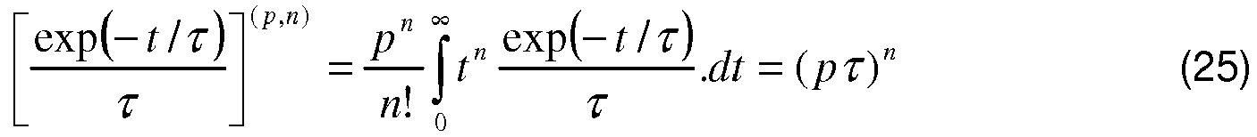
![]()
![]()
As ![]()
La transformée de Mellin-Laplace de la distribution temporelle mesurée Bsd est donc : ![]()
![]()
Après discrétisation du milieu en M voxels m, on obtient : ![]()
![]()
On inverse enfin ce système après discrétisation du milieu en voxels. On met alors en oeuvre un algorithme d'inversion, tel qu'un des algorithmes connus mentionnés précédemment, pour définir le vecteur F( ![]()
![]()
De manière analogue au premier mode de réalisation, la combinaison de différentes transformées de Mellin Laplace d'une grandeur ![]()
![]()
Claims (12)
- A method for reconstructing the optical properties of a medium (12), using a reconstruction system (10) comprising at least one radiation source (14, s) capable of lighting the medium (12) and at least one detector (16, d) capable of receiving a signal transmitted by the medium (12),
the method including the following steps:- lighting (100) the medium (12) using the or each radiation source (14, s),- receiving, by the or each detector (16, d), the signal transmitted by the medium (12), and- processing (110), for at least one source-detector pair (14, s, 16, d), a first distribution (Bsd(t)) of the signal received by the corresponding detector (16, d),- computing (130) the Mellin-Laplace transform (Ysd (p,n) ; Bsd (p,n)), for a given order (n) and a given variable (p), of a magnitude (Ysd(t) ; Bsd(t)) comprising the first distribution (Bsd(t)), the order (n) being an integer, the variable (p) being a real number, and- reconstructing (140) optical properties of the medium (12) using the Mellin-Laplace transform (Ysd (p,n) ; Bsd (p,n)) of said magnitude (Ysd(t) ; Bsd(t)),characterized in that the computing step (130) comprises computing a plurality of Mellin-Laplace transforms (Ysd (p,n) ; Bsd (p,n)) of said magnitude for distinct values of the order (n), and in that the reconstructing step (140) is carried out from a combination of the plurality of Mellin-Laplace transforms (Ysd (p,n) ; Bsd (p,n)). - The method according to claim 1, wherein the computing step (130) comprises computing at least one Mellin-Laplace transform (Ysd (p,n) ; Bsd (p,n)) of said magnitude for an order (n) value greater than or equal to 5, preferably greater than or equal to 8.
- The method according to claim 2, wherein the computing step (130) comprises the computing of nmax+1 Mellin-Laplace transforms (Ysd (p,n); Bsd (p,n)), the order (n) successively taking all values comprised between 0 and nmax, nmax being greater than or equal to 5, preferably greater than or equal to 8.
- The method according to any one of the preceding claims, wherein the value of the variable (p) is between 1 ns-1 and 20 ns-1.
- The method according to any one of the preceding claims, wherein the method also includes:- determining, for at least one source-detector pair (14, s, 16, d), a first modeling function (Gsd(t)) of a diffusion signal of the light between the source (14, s) and the detector (16, d) in the medium (12),- processing, for said at least one source-detector pair (14, s, 16, d), a second distribution (Asd(t)) of a signal received by the detector (16, d) for a reference medium (MR), the received signal being transmitted by the reference medium (MR) following the lighting of said medium (MR) by the source (14, s), and- determining, for said at least one source-detector pair (14, s, 16 d), a second modeling function (Gsd 0(t)) of a diffusion signal of the light between the source (14, s) and the detector (16, d) in the reference medium (MR),and wherein said magnitude (Ysd(t)) depends on the first distribution (Bsd(t)), the first modeling function (Gsd(t)), the second distribution (Asd(t)) and the second modeling function (Gsd 0(t)).
- The method according to claim 5, wherein said magnitude (Ysd(t)) is obtained by subtracting the product of the second distribution (Asd(t)) and the first modeling function (Gsd(t)) from the product of the first distribution (Bsd(t)) and the second modeling function (Gsd 0(t)).
- The method according to claim 5, wherein said magnitude (Ysd(t)) is the ratio between the product of the first distribution (Bsd(t)) and the second modeling function (Gsd 0(t)) and the product of the second distribution (Asd(t)) and the first modeling function (Gsd(t)).
- The method according to any one of the preceding claims, wherein the or each radiation source (14, s) comprises a pulsed light source.
- The method according to any one of the preceding claims, wherein the or each detector (16, d) is a time-resolved detector.
- The method according to any one of the preceding claims, wherein the optical properties include at least one element from amongst the group consisting of:- the light absorption properties, in particular characterized by the absorption coefficient (µa),- the diffusion properties, in particular characterized by the reduced diffusion coefficient (µ's) or the diffusion coefficient (D), and- the fluorescence properties, in particular characterized by a response function (F) of a fluorophore, or by a concentration (c) of the fluorophore, or by a magnitude depending on the quantity (q) of the fluorophore.
- A system (10) for reconstructing optical properties of a medium (12), including:- at least one radiation source (14, s) capable of lighting the medium (12),- at least one detector (16, d) capable of receiving a signal transmitted by the medium (12),- processing means (42) for processing a distribution (Bsd(t)) of the signal received by the corresponding detector (16, d) for at least one source-detector pair (14, s, 16, d),- computing means (44) for computing the Mellin-Laplace transform (Ysd (p,n) ; Bsd (p,n)), for a given order (n) and a given variable (p), of a magnitude (Ysd(t); Bsd(t)) comprising the distribution (Bsd(t)), the order (n) being an integer, the variable (p) being a real number, and- reconstructing means (46) for reconstructing the optical properties of the medium (12) using the Mellin-Laplace transform (Ysd (p,n) ; Bsd (p,n)) of said magnitude (Ysd(t) ; Bsd(t)),characterized in that the computing means (44) are capable of computing the plurality of Mellin-Laplace transforms (Ysd (p,n) ; Bsd (p,n)) of said magnitude for distinct values of the order (n), and in that the reconstructing means (46) are capable of reconstructing the optical properties of the medium (12) from a combination of the plurality of Mellin-Laplace transforms (Ysd (p,n) ; Bsd (p,n)).
- The system (10) according to claim 11, wherein the computing means (44) are capable of computing at least one Mellin-Laplace transform (Ysd (p,n); Bsd (p,n)) of said magnitude for an order (n) value greater than or equal to 5, preferably greater than or equal to 8.
Applications Claiming Priority (1)
| Application Number | Priority Date | Filing Date | Title |
|---|---|---|---|
| FR1161832A FR2984503B1 (en) | 2011-12-16 | 2011-12-16 | METHOD FOR RECONSTRUCTING OPTICAL PROPERTIES OF A DIFFUSING MEDIUM USING A COMBINATION OF A PLURALITY OF MELLIN-LAPLACE TRANSFORMS OF A SIZE INCLUDING A TIME DISTRIBUTION OF A RECEIVED SIGNAL, AND ASSOCIATED RECONSTRUCTION SYSTEM |
Publications (2)
| Publication Number | Publication Date |
|---|---|
| EP2605002A1 EP2605002A1 (en) | 2013-06-19 |
| EP2605002B1 true EP2605002B1 (en) | 2019-01-02 |
Family
ID=47297057
Family Applications (1)
| Application Number | Title | Priority Date | Filing Date |
|---|---|---|---|
| EP12197003.2A Active EP2605002B1 (en) | 2011-12-16 | 2012-12-13 | Method for reconstructing the optical properties of a scattering medium using a combination of a plurality of Mellin-Laplace transforms of a magnitude comprising a time distribution of a received signal, and associated reconstruction system |
Country Status (3)
| Country | Link |
|---|---|
| US (1) | US8817257B2 (en) |
| EP (1) | EP2605002B1 (en) |
| FR (1) | FR2984503B1 (en) |
Families Citing this family (37)
| Publication number | Priority date | Publication date | Assignee | Title |
|---|---|---|---|---|
| CN106330312B (en) * | 2016-08-31 | 2018-11-02 | 中国人民解放军信息工程大学 | A kind of underwater visible light communication method, apparatus and system |
| US10158038B1 (en) | 2018-05-17 | 2018-12-18 | Hi Llc | Fast-gated photodetector architectures comprising dual voltage sources with a switch configuration |
| WO2019221799A1 (en) | 2018-05-17 | 2019-11-21 | Hi Llc | Stacked photodetector assemblies |
| US10340408B1 (en) | 2018-05-17 | 2019-07-02 | Hi Llc | Non-invasive wearable brain interface systems including a headgear and a plurality of self-contained photodetector units configured to removably attach to the headgear |
| US10420498B1 (en) | 2018-06-20 | 2019-09-24 | Hi Llc | Spatial and temporal-based diffusive correlation spectroscopy systems and methods |
| US11213206B2 (en) | 2018-07-17 | 2022-01-04 | Hi Llc | Non-invasive measurement systems with single-photon counting camera |
| WO2020131148A1 (en) | 2018-12-21 | 2020-06-25 | Hi Llc | Biofeedback for awareness and modulation of mental state using a non-invasive brain interface system and method |
| WO2020226840A1 (en) | 2019-05-06 | 2020-11-12 | Hi Llc | Photodetector architectures for time-correlated single photon counting |
| US11081611B2 (en) | 2019-05-21 | 2021-08-03 | Hi Llc | Photodetector architectures for efficient fast-gating comprising a control system controlling a current drawn by an array of photodetectors with a single photon avalanche diode |
| JP7528125B2 (en) | 2019-06-06 | 2024-08-05 | エイチアイ エルエルシー | Photodetector system with low power time-to-digital converter architecture |
| WO2021167893A1 (en) | 2020-02-21 | 2021-08-26 | Hi Llc | Integrated detector assemblies for a wearable module of an optical measurement system |
| US11096620B1 (en) | 2020-02-21 | 2021-08-24 | Hi Llc | Wearable module assemblies for an optical measurement system |
| US12029558B2 (en) | 2020-02-21 | 2024-07-09 | Hi Llc | Time domain-based optical measurement systems and methods configured to measure absolute properties of tissue |
| WO2021167877A1 (en) | 2020-02-21 | 2021-08-26 | Hi Llc | Multimodal wearable measurement systems and methods |
| US11515014B2 (en) | 2020-02-21 | 2022-11-29 | Hi Llc | Methods and systems for initiating and conducting a customized computer-enabled brain research study |
| US11969259B2 (en) | 2020-02-21 | 2024-04-30 | Hi Llc | Detector assemblies for a wearable module of an optical measurement system and including spring-loaded light-receiving members |
| US11950879B2 (en) | 2020-02-21 | 2024-04-09 | Hi Llc | Estimation of source-detector separation in an optical measurement system |
| US11630310B2 (en) | 2020-02-21 | 2023-04-18 | Hi Llc | Wearable devices and wearable assemblies with adjustable positioning for use in an optical measurement system |
| WO2021188485A1 (en) | 2020-03-20 | 2021-09-23 | Hi Llc | Maintaining consistent photodetector sensitivity in an optical measurement system |
| WO2021188488A1 (en) | 2020-03-20 | 2021-09-23 | Hi Llc | Bias voltage generation in an optical measurement system |
| US12059262B2 (en) | 2020-03-20 | 2024-08-13 | Hi Llc | Maintaining consistent photodetector sensitivity in an optical measurement system |
| US11645483B2 (en) | 2020-03-20 | 2023-05-09 | Hi Llc | Phase lock loop circuit based adjustment of a measurement time window in an optical measurement system |
| US11903676B2 (en) | 2020-03-20 | 2024-02-20 | Hi Llc | Photodetector calibration of an optical measurement system |
| US11857348B2 (en) | 2020-03-20 | 2024-01-02 | Hi Llc | Techniques for determining a timing uncertainty of a component of an optical measurement system |
| US11607132B2 (en) | 2020-03-20 | 2023-03-21 | Hi Llc | Temporal resolution control for temporal point spread function generation in an optical measurement system |
| WO2021188489A1 (en) | 2020-03-20 | 2021-09-23 | Hi Llc | High density optical measurement systems with minimal number of light sources |
| US11245404B2 (en) | 2020-03-20 | 2022-02-08 | Hi Llc | Phase lock loop circuit based signal generation in an optical measurement system |
| US11877825B2 (en) | 2020-03-20 | 2024-01-23 | Hi Llc | Device enumeration in an optical measurement system |
| US11864867B2 (en) | 2020-03-20 | 2024-01-09 | Hi Llc | Control circuit for a light source in an optical measurement system by applying voltage with a first polarity to start an emission of a light pulse and applying voltage with a second polarity to stop the emission of the light pulse |
| US12059270B2 (en) | 2020-04-24 | 2024-08-13 | Hi Llc | Systems and methods for noise removal in an optical measurement system |
| US11941857B2 (en) | 2020-05-26 | 2024-03-26 | Hi Llc | Systems and methods for data representation in an optical measurement system |
| US11789533B2 (en) | 2020-09-22 | 2023-10-17 | Hi Llc | Synchronization between brain interface system and extended reality system |
| FR3118408B1 (en) | 2020-12-29 | 2022-11-11 | Commissariat Energie Atomique | Method for analyzing a sample by time-resolved measurement of the intensity of backscattered photons |
| WO2022150155A1 (en) | 2021-01-06 | 2022-07-14 | Hi Llc | Devices, systems, and methods using wearable time domain-based activity tracker |
| WO2022182526A1 (en) | 2021-02-26 | 2022-09-01 | Hi Llc | Brain activity tracking during electronic gaming |
| WO2022250817A1 (en) | 2021-05-26 | 2022-12-01 | Hi Llc | Graphical emotion symbol determination based on brain measurement data for use during an electronic messaging session |
| US12078531B2 (en) | 2021-07-28 | 2024-09-03 | Hi Llc | Devices, systems, and methods for calibrating an optical measurement device |
Family Cites Families (7)
| Publication number | Priority date | Publication date | Assignee | Title |
|---|---|---|---|---|
| US6856393B2 (en) * | 2002-08-21 | 2005-02-15 | The Board Of Trustees Of The Leland Stanford University | Method of measuring a physical function using a composite function which includes the physical function and an arbitrary reference function |
| US8831709B2 (en) * | 2004-09-24 | 2014-09-09 | Softscan Healthcare Group Ltd. | Method for 3-dimensional fluorescence tomographic imaging |
| FR2904691B1 (en) | 2006-08-02 | 2009-03-06 | Commissariat Energie Atomique | METHOD AND DEVICE FOR 3D RECONSTRUCTION OF THE DISTRIBUTION OF FLUORESCENT ELEMENTS |
| FR2938181B1 (en) * | 2008-11-13 | 2012-03-09 | Commissariat Energie Atomique | METHOD AND DEVICE FOR LOCATING FLUOROPHORES OR ABSORBERS IN A SURROUNDING ENVIRONMENT |
| FR2950241B1 (en) | 2009-09-18 | 2011-09-23 | Commissariat Energie Atomique | FANTOME BIOMODALITY OF ORGANS AND METHOD OF MAKING THE SAME |
| FR2984502B1 (en) * | 2011-12-16 | 2014-02-21 | Commissariat Energie Atomique | METHOD FOR RECONSTRUCTING THE OPTICAL PROPERTIES OF A MEDIUM WITH CALCULATION OF A CORRECTED SIGNAL BASED ON A FIRST MODELING FUNCTION FOR A REFERENCE MEDIUM AND A SECOND DISTRIBUTION FOR A MEDIA TO BE CHARACTERIZED, AND ASSOCIATED RECONSTRUCTION SYSTEM |
| FR2985023B1 (en) * | 2011-12-23 | 2016-05-06 | Commissariat Energie Atomique | SYSTEM FOR RECONSTRUCTING OPTICAL PROPERTIES OF A DIFFUSING MEDIUM, COMPRISING A PULSE RADIATION SOURCE AND AT LEAST TWO DETECTORS OF TWO DIFFERENT TYPES, AND ASSOCIATED RECONSTRUCTION METHOD |
-
2011
- 2011-12-16 FR FR1161832A patent/FR2984503B1/en active Active
-
2012
- 2012-12-13 EP EP12197003.2A patent/EP2605002B1/en active Active
- 2012-12-14 US US13/714,807 patent/US8817257B2/en active Active
Non-Patent Citations (1)
| Title |
|---|
| None * |
Also Published As
| Publication number | Publication date |
|---|---|
| FR2984503B1 (en) | 2014-01-17 |
| US20130155407A1 (en) | 2013-06-20 |
| EP2605002A1 (en) | 2013-06-19 |
| FR2984503A1 (en) | 2013-06-21 |
| US8817257B2 (en) | 2014-08-26 |
Similar Documents
| Publication | Publication Date | Title |
|---|---|---|
| EP2605002B1 (en) | Method for reconstructing the optical properties of a scattering medium using a combination of a plurality of Mellin-Laplace transforms of a magnitude comprising a time distribution of a received signal, and associated reconstruction system | |
| EP2606817B1 (en) | System for reconstructing optical properties of a scattering medium, including a source of pulsed radiation and at least two detectors of two different types, and associated reconstruction method | |
| EP2011083B1 (en) | Method for reconstruction of the distribution of fluorophores in a non-homogenous environment, by optical tomography in continuous mode | |
| EP2182343B1 (en) | Method and device for measuring the optical characteristics of an object | |
| EP2186469B1 (en) | Method and device for the localisation of fluorophores or absorbers in surrounding medium | |
| EP1884765B1 (en) | Method and device for the 3D reconstruction of the distribution of fluorescent elements | |
| EP3295153B1 (en) | Method of correcting a fluorescence image | |
| EP1971258B1 (en) | Method for reconstructing a fluorescence optical tomography three-dimensional image by double measurement | |
| EP2302362B1 (en) | Device and method for spatial reconstruction of a fluorescence cartography | |
| EP2762064A2 (en) | Method and system for calculating an indicator for quantifying a dermal reaction of the skin of a living being | |
| EP1994505B1 (en) | Method of reconstructing an optical tomography image by fluorescence of an object having any outline | |
| EP2605000B1 (en) | System and method for reconstruction of the optical properties of a medium with calculation of a corrected signal depending on a first model function for a reference medium and a second distribution within the medium to be characterised | |
| EP3054281A1 (en) | Device for measuring an optical signal backscattered by a sample | |
| EP3054282B1 (en) | Method for characterising a sample by measuring a backscattered optical signal | |
| EP2991544B1 (en) | Method and device for locating at least one target in an electromagnetically absorbent environment | |
| WO2020240131A1 (en) | Picosecond acoustic measuring system with double sensor beams | |
| EP1285256B1 (en) | Method of analysing a diffusing sample by time resolution measurement | |
| Nouizi et al. | 3D modeling of noncontact fiber-based approach for time-resolved diffuse optical tomography | |
| Guevara et al. | Comparison of the performance of two depth-resolved optical imaging systems: laminar optical tomography and spatially modulated imaging |
Legal Events
| Date | Code | Title | Description |
|---|---|---|---|
| PUAI | Public reference made under article 153(3) epc to a published international application that has entered the european phase |
Free format text: ORIGINAL CODE: 0009012 |
|
| AK | Designated contracting states |
Kind code of ref document: A1 Designated state(s): AL AT BE BG CH CY CZ DE DK EE ES FI FR GB GR HR HU IE IS IT LI LT LU LV MC MK MT NL NO PL PT RO RS SE SI SK SM TR |
|
| AX | Request for extension of the european patent |
Extension state: BA ME |
|
| 17P | Request for examination filed |
Effective date: 20131122 |
|
| RBV | Designated contracting states (corrected) |
Designated state(s): AL AT BE BG CH CY CZ DE DK EE ES FI FR GB GR HR HU IE IS IT LI LT LU LV MC MK MT NL NO PL PT RO RS SE SI SK SM TR |
|
| REG | Reference to a national code |
Ref country code: DE Ref legal event code: R079 Ref document number: 602012055375 Country of ref document: DE Free format text: PREVIOUS MAIN CLASS: G01N0021640000 Ipc: G01N0021470000 |
|
| GRAP | Despatch of communication of intention to grant a patent |
Free format text: ORIGINAL CODE: EPIDOSNIGR1 |
|
| STAA | Information on the status of an ep patent application or granted ep patent |
Free format text: STATUS: GRANT OF PATENT IS INTENDED |
|
| RIC1 | Information provided on ipc code assigned before grant |
Ipc: G01N 21/49 20060101ALI20180704BHEP Ipc: G01N 21/64 20060101ALI20180704BHEP Ipc: A61B 5/00 20060101ALI20180704BHEP Ipc: G01N 21/47 20060101AFI20180704BHEP Ipc: G09B 23/28 20060101ALN20180704BHEP Ipc: G01N 21/17 20060101ALN20180704BHEP |
|
| INTG | Intention to grant announced |
Effective date: 20180724 |
|
| GRAS | Grant fee paid |
Free format text: ORIGINAL CODE: EPIDOSNIGR3 |
|
| GRAA | (expected) grant |
Free format text: ORIGINAL CODE: 0009210 |
|
| STAA | Information on the status of an ep patent application or granted ep patent |
Free format text: STATUS: THE PATENT HAS BEEN GRANTED |
|
| AK | Designated contracting states |
Kind code of ref document: B1 Designated state(s): AL AT BE BG CH CY CZ DE DK EE ES FI FR GB GR HR HU IE IS IT LI LT LU LV MC MK MT NL NO PL PT RO RS SE SI SK SM TR |
|
| REG | Reference to a national code |
Ref country code: GB Ref legal event code: FG4D Free format text: NOT ENGLISH |
|
| REG | Reference to a national code |
Ref country code: CH Ref legal event code: EP Ref country code: AT Ref legal event code: REF Ref document number: 1085022 Country of ref document: AT Kind code of ref document: T Effective date: 20190115 |
|
| REG | Reference to a national code |
Ref country code: IE Ref legal event code: FG4D Free format text: LANGUAGE OF EP DOCUMENT: FRENCH |
|
| REG | Reference to a national code |
Ref country code: DE Ref legal event code: R096 Ref document number: 602012055375 Country of ref document: DE |
|
| REG | Reference to a national code |
Ref country code: NL Ref legal event code: MP Effective date: 20190102 |
|
| REG | Reference to a national code |
Ref country code: LT Ref legal event code: MG4D |
|
| REG | Reference to a national code |
Ref country code: AT Ref legal event code: MK05 Ref document number: 1085022 Country of ref document: AT Kind code of ref document: T Effective date: 20190102 |
|
| PG25 | Lapsed in a contracting state [announced via postgrant information from national office to epo] |
Ref country code: NL Free format text: LAPSE BECAUSE OF FAILURE TO SUBMIT A TRANSLATION OF THE DESCRIPTION OR TO PAY THE FEE WITHIN THE PRESCRIBED TIME-LIMIT Effective date: 20190102 |
|
| PG25 | Lapsed in a contracting state [announced via postgrant information from national office to epo] |
Ref country code: LT Free format text: LAPSE BECAUSE OF FAILURE TO SUBMIT A TRANSLATION OF THE DESCRIPTION OR TO PAY THE FEE WITHIN THE PRESCRIBED TIME-LIMIT Effective date: 20190102 Ref country code: FI Free format text: LAPSE BECAUSE OF FAILURE TO SUBMIT A TRANSLATION OF THE DESCRIPTION OR TO PAY THE FEE WITHIN THE PRESCRIBED TIME-LIMIT Effective date: 20190102 Ref country code: PL Free format text: LAPSE BECAUSE OF FAILURE TO SUBMIT A TRANSLATION OF THE DESCRIPTION OR TO PAY THE FEE WITHIN THE PRESCRIBED TIME-LIMIT Effective date: 20190102 Ref country code: ES Free format text: LAPSE BECAUSE OF FAILURE TO SUBMIT A TRANSLATION OF THE DESCRIPTION OR TO PAY THE FEE WITHIN THE PRESCRIBED TIME-LIMIT Effective date: 20190102 Ref country code: SE Free format text: LAPSE BECAUSE OF FAILURE TO SUBMIT A TRANSLATION OF THE DESCRIPTION OR TO PAY THE FEE WITHIN THE PRESCRIBED TIME-LIMIT Effective date: 20190102 Ref country code: NO Free format text: LAPSE BECAUSE OF FAILURE TO SUBMIT A TRANSLATION OF THE DESCRIPTION OR TO PAY THE FEE WITHIN THE PRESCRIBED TIME-LIMIT Effective date: 20190402 Ref country code: PT Free format text: LAPSE BECAUSE OF FAILURE TO SUBMIT A TRANSLATION OF THE DESCRIPTION OR TO PAY THE FEE WITHIN THE PRESCRIBED TIME-LIMIT Effective date: 20190502 |
|
| PG25 | Lapsed in a contracting state [announced via postgrant information from national office to epo] |
Ref country code: RS Free format text: LAPSE BECAUSE OF FAILURE TO SUBMIT A TRANSLATION OF THE DESCRIPTION OR TO PAY THE FEE WITHIN THE PRESCRIBED TIME-LIMIT Effective date: 20190102 Ref country code: HR Free format text: LAPSE BECAUSE OF FAILURE TO SUBMIT A TRANSLATION OF THE DESCRIPTION OR TO PAY THE FEE WITHIN THE PRESCRIBED TIME-LIMIT Effective date: 20190102 Ref country code: LV Free format text: LAPSE BECAUSE OF FAILURE TO SUBMIT A TRANSLATION OF THE DESCRIPTION OR TO PAY THE FEE WITHIN THE PRESCRIBED TIME-LIMIT Effective date: 20190102 Ref country code: IS Free format text: LAPSE BECAUSE OF FAILURE TO SUBMIT A TRANSLATION OF THE DESCRIPTION OR TO PAY THE FEE WITHIN THE PRESCRIBED TIME-LIMIT Effective date: 20190502 Ref country code: GR Free format text: LAPSE BECAUSE OF FAILURE TO SUBMIT A TRANSLATION OF THE DESCRIPTION OR TO PAY THE FEE WITHIN THE PRESCRIBED TIME-LIMIT Effective date: 20190403 Ref country code: BG Free format text: LAPSE BECAUSE OF FAILURE TO SUBMIT A TRANSLATION OF THE DESCRIPTION OR TO PAY THE FEE WITHIN THE PRESCRIBED TIME-LIMIT Effective date: 20190402 |
|
| REG | Reference to a national code |
Ref country code: DE Ref legal event code: R097 Ref document number: 602012055375 Country of ref document: DE |
|
| PG25 | Lapsed in a contracting state [announced via postgrant information from national office to epo] |
Ref country code: AL Free format text: LAPSE BECAUSE OF FAILURE TO SUBMIT A TRANSLATION OF THE DESCRIPTION OR TO PAY THE FEE WITHIN THE PRESCRIBED TIME-LIMIT Effective date: 20190102 Ref country code: CZ Free format text: LAPSE BECAUSE OF FAILURE TO SUBMIT A TRANSLATION OF THE DESCRIPTION OR TO PAY THE FEE WITHIN THE PRESCRIBED TIME-LIMIT Effective date: 20190102 Ref country code: RO Free format text: LAPSE BECAUSE OF FAILURE TO SUBMIT A TRANSLATION OF THE DESCRIPTION OR TO PAY THE FEE WITHIN THE PRESCRIBED TIME-LIMIT Effective date: 20190102 Ref country code: SK Free format text: LAPSE BECAUSE OF FAILURE TO SUBMIT A TRANSLATION OF THE DESCRIPTION OR TO PAY THE FEE WITHIN THE PRESCRIBED TIME-LIMIT Effective date: 20190102 Ref country code: EE Free format text: LAPSE BECAUSE OF FAILURE TO SUBMIT A TRANSLATION OF THE DESCRIPTION OR TO PAY THE FEE WITHIN THE PRESCRIBED TIME-LIMIT Effective date: 20190102 Ref country code: AT Free format text: LAPSE BECAUSE OF FAILURE TO SUBMIT A TRANSLATION OF THE DESCRIPTION OR TO PAY THE FEE WITHIN THE PRESCRIBED TIME-LIMIT Effective date: 20190102 Ref country code: IT Free format text: LAPSE BECAUSE OF FAILURE TO SUBMIT A TRANSLATION OF THE DESCRIPTION OR TO PAY THE FEE WITHIN THE PRESCRIBED TIME-LIMIT Effective date: 20190102 Ref country code: DK Free format text: LAPSE BECAUSE OF FAILURE TO SUBMIT A TRANSLATION OF THE DESCRIPTION OR TO PAY THE FEE WITHIN THE PRESCRIBED TIME-LIMIT Effective date: 20190102 |
|
| PLBE | No opposition filed within time limit |
Free format text: ORIGINAL CODE: 0009261 |
|
| STAA | Information on the status of an ep patent application or granted ep patent |
Free format text: STATUS: NO OPPOSITION FILED WITHIN TIME LIMIT |
|
| PG25 | Lapsed in a contracting state [announced via postgrant information from national office to epo] |
Ref country code: SM Free format text: LAPSE BECAUSE OF FAILURE TO SUBMIT A TRANSLATION OF THE DESCRIPTION OR TO PAY THE FEE WITHIN THE PRESCRIBED TIME-LIMIT Effective date: 20190102 |
|
| 26N | No opposition filed |
Effective date: 20191003 |
|
| PG25 | Lapsed in a contracting state [announced via postgrant information from national office to epo] |
Ref country code: SI Free format text: LAPSE BECAUSE OF FAILURE TO SUBMIT A TRANSLATION OF THE DESCRIPTION OR TO PAY THE FEE WITHIN THE PRESCRIBED TIME-LIMIT Effective date: 20190102 |
|
| PG25 | Lapsed in a contracting state [announced via postgrant information from national office to epo] |
Ref country code: TR Free format text: LAPSE BECAUSE OF FAILURE TO SUBMIT A TRANSLATION OF THE DESCRIPTION OR TO PAY THE FEE WITHIN THE PRESCRIBED TIME-LIMIT Effective date: 20190102 |
|
| REG | Reference to a national code |
Ref country code: CH Ref legal event code: PL |
|
| REG | Reference to a national code |
Ref country code: BE Ref legal event code: MM Effective date: 20191231 |
|
| PG25 | Lapsed in a contracting state [announced via postgrant information from national office to epo] |
Ref country code: MC Free format text: LAPSE BECAUSE OF FAILURE TO SUBMIT A TRANSLATION OF THE DESCRIPTION OR TO PAY THE FEE WITHIN THE PRESCRIBED TIME-LIMIT Effective date: 20190102 |
|
| PG25 | Lapsed in a contracting state [announced via postgrant information from national office to epo] |
Ref country code: LU Free format text: LAPSE BECAUSE OF NON-PAYMENT OF DUE FEES Effective date: 20191213 Ref country code: IE Free format text: LAPSE BECAUSE OF NON-PAYMENT OF DUE FEES Effective date: 20191213 |
|
| PG25 | Lapsed in a contracting state [announced via postgrant information from national office to epo] |
Ref country code: LI Free format text: LAPSE BECAUSE OF NON-PAYMENT OF DUE FEES Effective date: 20191231 Ref country code: CH Free format text: LAPSE BECAUSE OF NON-PAYMENT OF DUE FEES Effective date: 20191231 Ref country code: BE Free format text: LAPSE BECAUSE OF NON-PAYMENT OF DUE FEES Effective date: 20191231 |
|
| PG25 | Lapsed in a contracting state [announced via postgrant information from national office to epo] |
Ref country code: CY Free format text: LAPSE BECAUSE OF FAILURE TO SUBMIT A TRANSLATION OF THE DESCRIPTION OR TO PAY THE FEE WITHIN THE PRESCRIBED TIME-LIMIT Effective date: 20190102 |
|
| PG25 | Lapsed in a contracting state [announced via postgrant information from national office to epo] |
Ref country code: MT Free format text: LAPSE BECAUSE OF FAILURE TO SUBMIT A TRANSLATION OF THE DESCRIPTION OR TO PAY THE FEE WITHIN THE PRESCRIBED TIME-LIMIT Effective date: 20190102 Ref country code: HU Free format text: LAPSE BECAUSE OF FAILURE TO SUBMIT A TRANSLATION OF THE DESCRIPTION OR TO PAY THE FEE WITHIN THE PRESCRIBED TIME-LIMIT; INVALID AB INITIO Effective date: 20121213 |
|
| PG25 | Lapsed in a contracting state [announced via postgrant information from national office to epo] |
Ref country code: MK Free format text: LAPSE BECAUSE OF FAILURE TO SUBMIT A TRANSLATION OF THE DESCRIPTION OR TO PAY THE FEE WITHIN THE PRESCRIBED TIME-LIMIT Effective date: 20190102 |
|
| PGFP | Annual fee paid to national office [announced via postgrant information from national office to epo] |
Ref country code: GB Payment date: 20231221 Year of fee payment: 12 |
|
| PGFP | Annual fee paid to national office [announced via postgrant information from national office to epo] |
Ref country code: FR Payment date: 20231221 Year of fee payment: 12 Ref country code: DE Payment date: 20231219 Year of fee payment: 12 |