EP2405140B1 - Centrifugal pump device - Google Patents
Centrifugal pump device Download PDFInfo
- Publication number
- EP2405140B1 EP2405140B1 EP10748702.7A EP10748702A EP2405140B1 EP 2405140 B1 EP2405140 B1 EP 2405140B1 EP 10748702 A EP10748702 A EP 10748702A EP 2405140 B1 EP2405140 B1 EP 2405140B1
- Authority
- EP
- European Patent Office
- Prior art keywords
- impeller
- magnetic
- magnetic elements
- permanent magnets
- attractive force
- Prior art date
- Legal status (The legal status is an assumption and is not a legal conclusion. Google has not performed a legal analysis and makes no representation as to the accuracy of the status listed.)
- Not-in-force
Links
Images


Classifications
-
- F—MECHANICAL ENGINEERING; LIGHTING; HEATING; WEAPONS; BLASTING
- F04—POSITIVE - DISPLACEMENT MACHINES FOR LIQUIDS; PUMPS FOR LIQUIDS OR ELASTIC FLUIDS
- F04D—NON-POSITIVE-DISPLACEMENT PUMPS
- F04D25/00—Pumping installations or systems
- F04D25/02—Units comprising pumps and their driving means
- F04D25/026—Units comprising pumps and their driving means with a magnetic coupling
-
- F—MECHANICAL ENGINEERING; LIGHTING; HEATING; WEAPONS; BLASTING
- F04—POSITIVE - DISPLACEMENT MACHINES FOR LIQUIDS; PUMPS FOR LIQUIDS OR ELASTIC FLUIDS
- F04D—NON-POSITIVE-DISPLACEMENT PUMPS
- F04D13/00—Pumping installations or systems
- F04D13/02—Units comprising pumps and their driving means
- F04D13/06—Units comprising pumps and their driving means the pump being electrically driven
- F04D13/0666—Units comprising pumps and their driving means the pump being electrically driven the motor being of the plane gap type
-
- A—HUMAN NECESSITIES
- A61—MEDICAL OR VETERINARY SCIENCE; HYGIENE
- A61M—DEVICES FOR INTRODUCING MEDIA INTO, OR ONTO, THE BODY; DEVICES FOR TRANSDUCING BODY MEDIA OR FOR TAKING MEDIA FROM THE BODY; DEVICES FOR PRODUCING OR ENDING SLEEP OR STUPOR
- A61M60/00—Blood pumps; Devices for mechanical circulatory actuation; Balloon pumps for circulatory assistance
- A61M60/20—Type thereof
- A61M60/205—Non-positive displacement blood pumps
- A61M60/216—Non-positive displacement blood pumps including a rotating member acting on the blood, e.g. impeller
- A61M60/226—Non-positive displacement blood pumps including a rotating member acting on the blood, e.g. impeller the blood flow through the rotating member having mainly radial components
- A61M60/232—Centrifugal pumps
-
- A—HUMAN NECESSITIES
- A61—MEDICAL OR VETERINARY SCIENCE; HYGIENE
- A61M—DEVICES FOR INTRODUCING MEDIA INTO, OR ONTO, THE BODY; DEVICES FOR TRANSDUCING BODY MEDIA OR FOR TAKING MEDIA FROM THE BODY; DEVICES FOR PRODUCING OR ENDING SLEEP OR STUPOR
- A61M60/00—Blood pumps; Devices for mechanical circulatory actuation; Balloon pumps for circulatory assistance
- A61M60/40—Details relating to driving
- A61M60/403—Details relating to driving for non-positive displacement blood pumps
- A61M60/419—Details relating to driving for non-positive displacement blood pumps the force acting on the blood contacting member being permanent magnetic, e.g. from a rotating magnetic coupling between driving and driven magnets
-
- A—HUMAN NECESSITIES
- A61—MEDICAL OR VETERINARY SCIENCE; HYGIENE
- A61M—DEVICES FOR INTRODUCING MEDIA INTO, OR ONTO, THE BODY; DEVICES FOR TRANSDUCING BODY MEDIA OR FOR TAKING MEDIA FROM THE BODY; DEVICES FOR PRODUCING OR ENDING SLEEP OR STUPOR
- A61M60/00—Blood pumps; Devices for mechanical circulatory actuation; Balloon pumps for circulatory assistance
- A61M60/40—Details relating to driving
- A61M60/403—Details relating to driving for non-positive displacement blood pumps
- A61M60/422—Details relating to driving for non-positive displacement blood pumps the force acting on the blood contacting member being electromagnetic, e.g. using canned motor pumps
-
- A—HUMAN NECESSITIES
- A61—MEDICAL OR VETERINARY SCIENCE; HYGIENE
- A61M—DEVICES FOR INTRODUCING MEDIA INTO, OR ONTO, THE BODY; DEVICES FOR TRANSDUCING BODY MEDIA OR FOR TAKING MEDIA FROM THE BODY; DEVICES FOR PRODUCING OR ENDING SLEEP OR STUPOR
- A61M60/00—Blood pumps; Devices for mechanical circulatory actuation; Balloon pumps for circulatory assistance
- A61M60/80—Constructional details other than related to driving
- A61M60/802—Constructional details other than related to driving of non-positive displacement blood pumps
- A61M60/818—Bearings
- A61M60/824—Hydrodynamic or fluid film bearings
-
- F—MECHANICAL ENGINEERING; LIGHTING; HEATING; WEAPONS; BLASTING
- F04—POSITIVE - DISPLACEMENT MACHINES FOR LIQUIDS; PUMPS FOR LIQUIDS OR ELASTIC FLUIDS
- F04D—NON-POSITIVE-DISPLACEMENT PUMPS
- F04D13/00—Pumping installations or systems
- F04D13/02—Units comprising pumps and their driving means
- F04D13/021—Units comprising pumps and their driving means containing a coupling
- F04D13/024—Units comprising pumps and their driving means containing a coupling a magnetic coupling
- F04D13/026—Details of the bearings
-
- F—MECHANICAL ENGINEERING; LIGHTING; HEATING; WEAPONS; BLASTING
- F04—POSITIVE - DISPLACEMENT MACHINES FOR LIQUIDS; PUMPS FOR LIQUIDS OR ELASTIC FLUIDS
- F04D—NON-POSITIVE-DISPLACEMENT PUMPS
- F04D13/00—Pumping installations or systems
- F04D13/02—Units comprising pumps and their driving means
- F04D13/021—Units comprising pumps and their driving means containing a coupling
- F04D13/024—Units comprising pumps and their driving means containing a coupling a magnetic coupling
- F04D13/027—Details of the magnetic circuit
-
- F—MECHANICAL ENGINEERING; LIGHTING; HEATING; WEAPONS; BLASTING
- F04—POSITIVE - DISPLACEMENT MACHINES FOR LIQUIDS; PUMPS FOR LIQUIDS OR ELASTIC FLUIDS
- F04D—NON-POSITIVE-DISPLACEMENT PUMPS
- F04D17/00—Radial-flow pumps, e.g. centrifugal pumps; Helico-centrifugal pumps
- F04D17/08—Centrifugal pumps
- F04D17/10—Centrifugal pumps for compressing or evacuating
-
- F—MECHANICAL ENGINEERING; LIGHTING; HEATING; WEAPONS; BLASTING
- F04—POSITIVE - DISPLACEMENT MACHINES FOR LIQUIDS; PUMPS FOR LIQUIDS OR ELASTIC FLUIDS
- F04D—NON-POSITIVE-DISPLACEMENT PUMPS
- F04D29/00—Details, component parts, or accessories
- F04D29/04—Shafts or bearings, or assemblies thereof
- F04D29/046—Bearings
- F04D29/048—Bearings magnetic; electromagnetic
-
- A—HUMAN NECESSITIES
- A61—MEDICAL OR VETERINARY SCIENCE; HYGIENE
- A61M—DEVICES FOR INTRODUCING MEDIA INTO, OR ONTO, THE BODY; DEVICES FOR TRANSDUCING BODY MEDIA OR FOR TAKING MEDIA FROM THE BODY; DEVICES FOR PRODUCING OR ENDING SLEEP OR STUPOR
- A61M60/00—Blood pumps; Devices for mechanical circulatory actuation; Balloon pumps for circulatory assistance
- A61M60/10—Location thereof with respect to the patient's body
- A61M60/122—Implantable pumps or pumping devices, i.e. the blood being pumped inside the patient's body
- A61M60/126—Implantable pumps or pumping devices, i.e. the blood being pumped inside the patient's body implantable via, into, inside, in line, branching on, or around a blood vessel
- A61M60/148—Implantable pumps or pumping devices, i.e. the blood being pumped inside the patient's body implantable via, into, inside, in line, branching on, or around a blood vessel in line with a blood vessel using resection or like techniques, e.g. permanent endovascular heart assist devices
Definitions
- the present invention relates to a centrifugal pump apparatus, and particularly to a centrifugal pump apparatus including an impeller for delivering liquid by centrifugal force during rotation.
- centrifugal blood pump apparatus in which driving torque from an external motor is transmitted to an impeller in a blood chamber through magnetic coupling has increasingly been used as a blood circulation apparatus of an artificial heart-lung machine. According to such a centrifugal blood pump apparatus, physical contact between the blood chamber and the outside can be eliminated, thus preventing invasion of bacteria and the like into blood.
- a centrifugal blood pump in PTL 1 includes a housing having first to third chambers partitioned from one another by first and second diaphragms, an impeller rotatably provided in the second chamber (blood chamber), a magnetic element provided in one surface of the impeller, an electromagnet provided in the first chamber to face the one surface of the impeller, a permanent magnet provided in the other surface of the impeller, a rotor and a motor provided in the third chamber, and a permanent magnet provided in the rotor to face the other surface of the impeller.
- a groove for hydrodynamic bearing is formed in a surface of the second diaphragm facing the other surface of the impeller.
- the impeller moves away from an inner surface of the second chamber and rotates without contacting.
- a centrifugal blood pump in PTL 2 includes a housing having first to third chambers partitioned from one another by first and second diaphragms, an impeller rotatably provided in the second chamber (blood chamber), a magnetic element provided in one surface of the impeller, a first permanent magnet provided in the first chamber to face the one surface of the impeller, a second permanent magnet provided in the other surface of the impeller, a rotor and a motor provided in the third chamber, and a third permanent magnet provided in the rotor to face the other surface of the impeller.
- a first hydrodynamic bearing is formed in a surface of the first diaphragm facing the one surface of the impeller, and a second groove for hydrodynamic bearing is formed in a surface of the second diaphragm facing the other surface of the impeller.
- a turbo-type pump in Figs. 8 and 9 of PTL 3 includes a housing, an impeller rotatably provided in the housing, a first permanent magnet provided in one surface of the impeller, a rotor provided outside the housing, a second permanent magnet provided in the rotor to face the one surface of the impeller, a third permanent magnet provided in the other surface of the impeller, and a magnetic element provided in the housing to face the other surface of the impeller.
- a first groove for hydrodynamic bearing is formed in the one surface of the impeller, and a second groove for hydrodynamic bearing is formed in the other surface of the impeller.
- the impeller moves away from an inner surface of the housing and rotates without contacting.
- a clean pump in PTL 4 Japanese Utility Model Laying-Open No. 6-53790 ) includes a casing, an impeller rotatably provided in the casing, a first permanent magnet provided in one surface of the impeller, a rotor provided outside the casing, a second permanent magnet provided in the rotor to face the one surface of the impeller, a magnetic element provided in the other surface of the impeller, and an electromagnet provided outside a housing to face the other surface of the impeller.
- a groove for hydrodynamic bearing is formed in the one surface of the impeller.
- the electromagnet is actuated when a rotation speed of the impeller is lower than a prescribed rotation speed, and power supply to the electromagnet is stopped when the rotation speed of the impeller becomes higher than the prescribed rotation speed.
- the impeller moves away from an inner surface of the housing and rotates without contacting.
- the blood pump has electromagnets for rotating a rotating body in a non-contact condition, and a hydrodynamic bearing section for rotating the rotating body in a non-contact condition when operation of the electromagnets is stopped.
- the control mechanism includes a pulse width modulation type electromagnet driving unit, a carrier component measuring unit for measuring carrier components of voltage and current in the driving unit, a modulation factor calculating unit which calculates a modulation factor using the carrier wave data, and a bearing mode changing-over mechanism for effecting change-over from the magnetic bearing mode to the hydrodynamic bearing mode when the calculated modulation factor is outside a predetermined range and for returning to the magnetic bearing mode after the change-over.
- the pumps in PTLs 1 to 4 described above are common in the feature of axially (in a direction of a rotation axis of the impeller) supporting the impeller by the grooves for hydrodynamic bearing formed in a portion where the impeller and the housing face each other and radially (in a direction of a radius of the impeller) supporting the impeller by the attractive force between the permanent magnet provided in the impeller and the permanent magnet provided outside the housing.
- magnetic coupling force between the permanent magnet in the impeller and the permanent magnet on the housing side should only be increased. It is not easy, however, to increase that magnetic coupling force. Namely, in a hydrodynamic bearing type centrifugal pump apparatus, initially, a flow rate, a pump head (pressure), and a minimum value of an interval between the blood chamber and the impeller are provided as the specifications. Then, a diameter of the impeller determines a rotation speed and a dimension of a groove for hydrodynamic bearing.
- a load capacity is determined and hence magnetic coupling force balanced therewith is determined.
- rigidity for supporting the impeller is also determined. Therefore, though it is necessary to increase the load capacity in order to increase rigidity for supporting the impeller, increase in the load capacity is limited, because the load capacity is dependent on viscosity of blood, a rotation speed of the impeller, a dimension of a groove for hydrodynamic bearing, and an interval between the blood chamber and the impeller.
- a gap between an end surface of the impeller and an inner surface of the housing on which hydrodynamic pressure acts is formed on a side of an impeller rotational torque generation portion and on a side of an impeller auxiliary attracting portion.
- a main object of the present invention is to provide a centrifugal pump apparatus having resistance to disturbance acting on an impeller, in which a gap for levitation between the impeller and a housing is not varied even when the impeller radially moves in the housing.
- a centrifugal pump apparatus is a centrifugal pump apparatus including a housing having first and second chambers partitioned from each other by a diaphragm, an impeller rotatably provided in the first chamber along the diaphragm, for delivering liquid by centrifugal force during rotation, and drive means provided in the second chamber for driving the impeller to rotate with the diaphragm being interposed, and it includes a first magnetic element provided in one surface of the impeller, a second magnetic element provided in an inner wall of the first chamber facing the one surface of the impeller, for attracting the first magnetic element, and a third magnetic element provided in the other surface of the impeller.
- first attractive force between the first and second magnetic elements and second attractive force between the third magnetic element and the drive means are balanced with each other substantially in a center of a movable range of the impeller in the first chamber.
- An amount of change in the first attractive force with respect to an amount of eccentricity in a radial direction of the impeller is substantially equal to an amount of change in the second attractive force with respect to the amount of eccentricity in the radial direction of the impeller.
- a first groove for hydrodynamic bearing is formed in the one surface of the impeller or in the inner wall of the first chamber facing the one surface, and a second groove for hydrodynamic bearing is formed in the other surface of the impeller or in the diaphragm facing the other surface.
- the third magnetic element includes a plurality of magnets arranged along the same circle such that adjacent magnetic polarities are different from each other, and the drive means includes a plurality of coils provided to face the plurality of magnets, for generating rotating magnetic field. Furthermore, the second attractive force is adjusted by varying a phase of a current fed to the plurality of coils.
- the drive means includes a rotor rotatably provided along the diaphragm in the second chamber, a fourth magnetic element provided in the rotor, for attracting the third magnetic element, and a motor for rotating the rotor.
- an absolute value of a positive supporting rigidity value in the radial direction of a magnetic coupling portion constituted of the first and second magnetic elements is greater than an absolute value of a positive supporting rigidity value in a radial direction of a magnetic coupling portion constituted of the third and fourth magnetic elements.
- the third magnetic element includes a plurality of magnets arranged along the same circle such that adjacent magnetic polarities are different from each other.
- the drive means includes a plurality of fourth magnetic elements provided to face the plurality of magnets and a plurality of coils provided in correspondence with the plurality of fourth magnetic elements respectively and each wound around the corresponding fourth magnetic element, for generating rotating magnetic field.
- the centrifugal pump apparatus further includes a magnetic sensor provided in the second chamber to face the plurality of magnets, and a phase of a current fed to the plurality of coils is varied based on an output signal from the magnetic sensor.
- the centrifugal pump apparatus further includes a plurality of the first magnetic elements provided in one surface of the impeller and aligned in a radial direction of the impeller and a plurality of the second magnetic elements provided in the inner wall of the first chamber facing the one surface of the impeller and attracting the plurality of first magnetic elements respectively.
- first attractive force between the plurality of first magnetic elements and the plurality of second magnetic elements and second attractive force between the third magnetic element and the drive unit are balanced with each other substantially in the center of the movable range of the impeller in the first chamber.
- At least one magnetic element of the plurality of first magnetic elements and the plurality of second magnetic elements is formed annularly around a rotation centerline of the impeller.
- At least one magnetic element of the plurality of first magnetic elements and the plurality of second magnetic elements are formed as multiple pieces annularly around a rotation centerline of the impeller.
- each of the plurality of first magnetic elements and the plurality of second magnetic elements is a permanent magnet, and N poles of two first magnetic elements adjacent in the radial direction of the impeller are oriented in an identical direction.
- each of the plurality of first magnetic elements and the plurality of second magnetic elements is a permanent magnet, and N poles of two first magnetic elements adjacent in the radial direction of the impeller are oriented in directions different from each other.
- an interval between two first magnetic elements adjacent in the radial direction of the impeller is greater than 1/2 of a movable distance of the impeller in the radial direction in the first chamber. In this case, even when the impeller moves in the radial direction to a maximum extent, magnetic interference between two adjacent pairs of first and second magnetic elements can be avoided.
- the drive means includes a plurality of coils provided in correspondence with the plurality of third magnetic elements respectively, for generating rotating magnetic field.
- the drive means includes a plurality of fourth magnetic elements arranged to face the plurality of third magnetic elements and a plurality of coils provided in correspondence with the plurality of fourth magnetic elements respectively and each wound around the corresponding fourth magnetic element, for generating rotating magnetic field.
- the drive means includes a rotor rotatably provided along the diaphragm in the second chamber, a fourth magnetic element provided in the rotor to face the third magnetic element, for attracting the third magnetic element, and a motor for rotating the rotor.
- the liquid is blood and the centrifugal pump apparatus is used for circulating the blood.
- the impeller is smoothly activated to rotate and a distance between the impeller and the housing is secured, thereby preventing occurrence of hemolysis.
- first and second attractive forces acting on the impeller are balanced with each other substantially in the center of the movable range of the impeller, amounts of change in the first and second attractive forces with respect to an amount of eccentricity in the radial direction of the impeller are made substantially equal to each other, and first and second grooves for hydrodynamic bearing are formed. Therefore, even when the impeller moves in the radial direction in the housing, a gap for levitation between the impeller and the housing is not varied and thus resistance to disturbance acting on the impeller can be improved.
- a pump unit 1 of a centrifugal blood pump apparatus includes a housing 2 made of a nonmagnetic material.
- Housing 2 includes a cylindrical body portion 3, a cylindrical blood inlet port 4 provided to stand at a center of one end surface of body portion 3, and a cylindrical blood outlet port 5 provided on an outer circumferential surface of body portion 3.
- Blood outlet port 5 extends in a tangential direction of the outer circumferential surface of body portion 3.
- a blood chamber 7 and a motor chamber 8 partitioned from each other by a diaphragm 6 are provided in housing 2, as shown in Fig. 3 .
- a disc-shaped impeller 10 having a through hole 10a in a center thereof is rotatably provided in blood chamber 7, as shown in Figs. 3 and 4 .
- Impeller 10 includes two shrouds 11, 12 in a doughnut plate shape, and a plurality of (e.g., six) vanes 13 formed between two shrouds 11 and 12.
- Shroud 11 is arranged on the blood inlet port 4 side and shroud 12 is arranged on the diaphragm 6 side.
- Shrouds 11, 12 and vanes 13 are made of a nonmagnetic material.
- a plurality of (six in this case) blood passages 14 partitioned from one another by the plurality of vanes 13 are formed between two shrouds 11 and 12.
- blood passage 14 is in communication with through hole 10a in the center of impeller 10, and it extends with through hole 10a in impeller 10 as a starting point to an outer circumference such that blood passage 14 gradually increases in width.
- vane 13 is formed between two adjacent blood passages 14.
- the plurality of vanes 13 are formed at regular angular intervals, and they have the same shape.
- the plurality of blood passages 14 are provided at regular angular intervals and they have the same shape.
- Permanent magnets 15a, 15b are embedded in shroud 11 and permanent magnets 16a, 16b for attracting permanent magnets 15a, 15b respectively are embedded in an inner wall of blood chamber 7 facing shroud 11. Permanent magnets 15a, 15b, 16a, and 16b are provided to attract (in other words, bias) impeller 10 to the side opposite to motor chamber 8, that is, toward blood inlet port 4.
- Figs. 5 (a) and (b) are diagrams showing a structure of permanent magnets 15a, 15b, 16a, and 16b and Fig. 5 (a) is a cross-sectional view along the line VA-VA in Fig. 5 (b) .
- each of permanent magnets 15a, 15b is formed annularly, and an outer diameter of permanent magnet 15a is smaller than an inner diameter of permanent magnet 15b.
- Permanent magnets 15a, 15b are coaxially provided, and central points of respective permanent magnets 15a, 15b are both arranged on a rotation centerline of impeller 10. Though end surfaces of respective permanent magnets 15a, 15b in the same direction have the same polarity in the figure, they may be constructed to be different in polarity.
- each of permanent magnets 16a, 16b is formed in an arc shape, and two permanent magnets are aligned in a direction of rotation of impeller 10.
- An outer diameter and an inner diameter of two permanent magnets 16a arranged annularly are the same as the outer diameter and the inner diameter of permanent magnet 15a, respectively.
- An outer diameter and an inner diameter of two permanent magnets 16b arranged annularly are the same as the outer diameter and the inner diameter of permanent magnet 15b, respectively.
- end surfaces of respective permanent magnets 16a, 16b in the same direction have the same polarity in the figure, they may be constructed to be different in polarity.
- Permanent magnets 15a and 16a face each other and permanent magnets 15b and 16b face each other, in such polarity arrangement as one attracting the other.
- an interval between permanent magnets 15a and 15b (that is, an interval between permanent magnets 16a and 16b) D1 is set to be greater than a distance D2 which is half a movable distance of impeller 10 in the radial direction (that is, a distance of a difference between the inner diameter of blood chamber 7 and the outer diameter of impeller 10) (D1>D2).
- a permanent magnet may be provided in one of shroud 11 and the inner wall of blood chamber 7, and a magnetic element may be provided in the other. Either a soft magnetic element or a hard magnetic element may be used as the magnetic element.
- FIG. 3 shows a case where opposing surfaces of permanent magnets 15a and 16a are identical in size and opposing surfaces of permanent magnets 15b and 16b are identical in size, in order to prevent lowering in rigidity of impeller 10 due to attractive force of permanent magnets 15a, 15b and permanent magnets 16a, 16b, preferably, opposing surfaces of permanent magnets 15a and 16a are different in size from each other and opposing surfaces of permanent magnets 15b and 16b are different in size from each other.
- an amount of change in attractive force that is, negative rigidity, which varies depending on a distance therebetween, can be suppressed to be small and lowering in rigidity for supporting impeller 10 can be prevented.
- each of permanent magnets 15a, 15b is annularly formed, and each of permanent magnets 16a, 16b is formed in an arc shape and two of the permanent magnets are aligned at regular angular intervals in a direction of rotation of impeller 10.
- each of permanent magnets 16a, 16b may be formed annularly, and each of permanent magnets 15a, 15b may be formed in an arc shape and two of the permanent magnets may be aligned at regular angular intervals in a direction of rotation of impeller 10.
- each of permanent magnets 15a, 15b or each of permanent magnets 16a, 16b may be formed in a shorter arc shape and a plurality of the permanent magnets may be aligned at regular angular intervals in a direction of rotation of impeller 10.
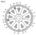
- a plurality of (e.g., eight) permanent magnets 17 are embedded in shroud 12.
- the plurality of permanent magnets 17 are arranged at regular angular intervals along the same circle such that adjacent magnetic polarities thereof are different from each other.
- permanent magnet 17 having the N-pole toward motor chamber 8 and permanent magnet 17 having the S-pole toward motor chamber 8 are alternately arranged at regular angular intervals along the same circle.
- a plurality of (e.g., nine) magnetic elements 18 are provided in motor chamber 8.
- the plurality of magnetic elements 18 are arranged at regular angular intervals along the same circle to face the plurality of permanent magnets 17 in impeller 10.
- a base end of each of the plurality of magnetic elements 18 is joined to one disc-shaped yoke 19.
- a coil 20 is wound around each magnetic element 18.
- Three magnetic sensors SE are provided among four adjacent magnetic elements 18 among nine magnetic elements 18.
- Three magnetic sensors SE are arranged to face paths in impeller 10, through which the plurality of permanent magnets 17 pass. As impeller 10 rotates and the S pole and the N pole of the plurality of permanent magnets 17 alternately pass by the vicinity of magnetic sensor SE, a level of an output signal from magnetic sensor SE varies sinusoidally as shown in Fig. 9 . Therefore, by detecting temporal change in the output signal from magnetic sensor SE, positional relation between the plurality of permanent magnets 17 and the plurality of magnetic elements 18 can be detected and timing to feed a current to the plurality of coils 20 and the rotation speed of impeller 10 can be found.
- Voltages are applied to nine coils 20 in a power distribution system shifted by 120 degrees, for example. That is, nine coils 20 are divided into groups each including three coils. Voltages VU, VV and VW as shown in Fig. 10 are applied to first to third coils 20 of each group, respectively.
- a positive voltage is applied during a period of 0 to 120 degrees
- 0 V is applied during a period of 120 to 180 degrees
- a negative voltage is applied during a period of 180 to 300 degrees
- 0 V is applied during a period of 300 to 360 degrees.
- a tip surface of magnetic element 18 having first coil 20 wound therearound becomes the N-pole during the period of 0 to 120 degrees and becomes the S-pole during the period of 180 to 300 degrees.
- Voltage VV is delayed in phase from voltage VU by 120 degrees
- voltage VW is delayed in phase from voltage VV by 120 degrees.
- rotating magnetic field can be formed by applying voltages VU, VV and VW to first to third coils 20, respectively, so that impeller 10 can be rotated by attractive force and repulsion force between the plurality of magnetic elements 18 and the plurality of permanent magnets 17 in impeller 10.
- a surface of impeller 10 and a surface of an inner wall of housing 2 are not damaged (no projections and recesses in the surfaces) during the relative slide, and moreover, impeller 10 is readily levitated from housing 2 without contacting even when hydrodynamic pressure is low during low-speed rotation. Accordingly, occurrence of hemolysis due to the relative slide between impeller 10 and housing 2 or occurrence of thrombus due to small damage (projections and recesses) to the surfaces which occurs during the relative slide is avoided.
- a plurality of grooves for hydrodynamic bearing 21 are formed in a surface of diaphragm 6 facing shroud 12 of impeller 10, and a plurality of grooves for hydrodynamic bearing 22 are formed in the inner wall of blood chamber 7 facing shroud 11.
- a rotation speed of impeller 10 becomes higher than a prescribed rotation speed, a hydrodynamic bearing effect is produced between each of grooves for hydrodynamic bearing 21, 22 and impeller 10.
- drag is generated on impeller 10 from each of grooves for hydrodynamic bearing 21, 22, causing impeller 10 to rotate without contacting in blood chamber 7.
- the plurality of grooves for hydrodynamic bearing 21 are each formed with a size corresponding to shroud 12 of impeller 10.
- Each of grooves for hydrodynamic bearing 21 has one end on an edge (circumference) of a circular portion slightly distant from a center of diaphragm 6, and extends spirally (in other words, in a curved manner) toward a portion near an outer edge of diaphragm 6 such that groove for hydrodynamic bearing 21 gradually increases in width.
- the plurality of grooves for hydrodynamic bearing 21 have substantially the same shape, and they are arranged at substantially regular intervals.
- Groove for hydrodynamic bearing 21 is a concave portion, and it preferably has a depth of about 0.005 to 0.4 mm. It is preferable that about 6 to 36 grooves for hydrodynamic bearing 21 be provided.
- ten grooves for hydrodynamic bearing 21 are arranged equiangularly with respect to a central axis of impeller 10. Since groove for hydrodynamic bearing 21 has a so-called inward spiral groove shape, clockwise rotation of impeller 10 causes increase in liquid pressure from an outer diameter portion toward an inner diameter portion of groove for hydrodynamic bearing 21. As a result, repulsion force is generated between impeller 10 and diaphragm 6 and it acts as hydrodynamic pressure.
- impeller 10 moves away from diaphragm 6 and rotates without contacting. Accordingly, a blood flow path is secured between impeller 10 and diaphragm 6, thus preventing occurrence of blood accumulation therebetween and the resultant thrombus. Further, in a normal state, grooves for hydrodynamic bearing 21 perform a stirring function between impeller 10 and diaphragm 6, thus preventing occurrence of partial blood accumulation therebetween.
- grooves for hydrodynamic bearing 21 may be provided in a surface of shroud 12 of impeller 10.
- a corner portion of groove for hydrodynamic bearing 21 be rounded to have R of at least 0.05 mm. As a result, occurrence of hemolysis can further be lessened.
- the plurality of grooves for hydrodynamic bearing 22 are formed with a size corresponding to shroud 11 of impeller 10.
- Each of grooves for hydrodynamic bearing 22 has one end on the edge (circumference) of the circular portion slightly distant from the center of the inner wall of blood chamber 7, and extends spirally (in other words, in a curved manner) toward the portion near the outer edge of the inner wall of blood chamber 7 such that groove for hydrodynamic bearing 22 gradually increases in width.
- the plurality of grooves for hydrodynamic bearing 22 have substantially the same shape and they are arranged at substantially regular intervals.
- Groove for hydrodynamic bearing 22 is a concave portion and it preferably has a depth of about 0.005 to 0.4 mm. It is preferable that about 6 to 36 grooves for hydrodynamic bearing 22 be provided. In Fig. 7 , ten grooves for hydrodynamic bearing 22 are equiangularly arranged with respect to the central axis of impeller 10.
- impeller 10 moves away from the inner wall of blood chamber 7 and rotates without contacting.
- impeller 10 can be prevented from being in close contact with the inner wall of blood chamber 7.
- the hydrodynamic pressure generated by grooves for hydrodynamic bearing 21 may be different from the hydrodynamic pressure generated by grooves for hydrodynamic bearing 22.
- Grooves for hydrodynamic bearing 22 may be provided in a surface of shroud 11 of impeller 10, rather than on the inner surface side of blood chamber 7. It is preferable that a comer portion of groove for hydrodynamic bearing 22 be rounded to have R of at least 0.05 mm. As a result, occurrence of hemolysis can further be lessened.
- impeller 10 rotate in a state where a gap between shroud 12 of impeller 10 and diaphragm 6 is substantially equal to a gap between shroud 11 of impeller 10 and the inner wall of blood chamber 7. If one of the gaps becomes narrower due to serious disturbance such as hydrodynamic force acting on impeller 10, it is preferable that grooves for hydrodynamic bearing 21 and 22 have different shapes, so that the hydrodynamic pressure generated by the grooves for hydrodynamic bearing on the narrower side becomes higher than the hydrodynamic pressure generated by the other grooves for hydrodynamic bearing to make the gaps substantially equal to each other.
- grooves for hydrodynamic bearing 21 and 22 have the inward spiral groove shape in Figs. 6 and 7
- grooves for hydrodynamic bearing 21 and 22 having another shape may be used. Nevertheless, for blood circulation, it is preferable to employ grooves for hydrodynamic bearing 21 and 22 having the inward spiral groove shape that allows smooth flow of blood.
- Fig. 11 is a diagram showing forces acting on impeller 10 when magnitude of a resultant force of an attractive force F1 between permanent magnets 15a, 15b and permanent magnets 16a, 16b (abbreviated as between permanent magnets 15 and 16 in Fig. 11 ) and an attractive force F2 between permanent magnet 17 and magnetic element 18 is adjusted to zero at a position P1 other than a central position of the movable range of impeller 10 in blood chamber 7.
- the rotation speed of impeller 10 is kept at a rated value.
- attractive force F1 between permanent magnets 15a, 15b and permanent magnets 16a, 16b is set to be smaller than attractive force F2 between permanent magnet 17 and magnetic element 18 and a levitation position of impeller 10 where their resultant force becomes zero is on the diaphragm 6 side relative to the center of the movable range of the impeller.
- Grooves for hydrodynamic bearing 21, 22 have the same shape.
- a horizontal axis of Fig. 11 represents a position of impeller 10 (the left side in the figure being the diaphragm 6 side) and a vertical axis represents forces acting on impeller 10.
- Force acting on impeller 10 toward the diaphragm 6 side is expressed as a negative acting force.
- attractive force F1 between permanent magnets 15a, 15b and permanent magnets 16a, 16b attractive force F2 between permanent magnet 17 and magnetic element 18, a hydrodynamic pressure F3 generated by grooves for hydrodynamic bearing 21, a hydrodynamic pressure F4 generated by grooves for hydrodynamic bearing 22, and "net force F5 acting on impeller," which is their resultant force, are illustrated.
- Fig. 12 is a diagram showing forces acting on impeller 10 when magnitude of the resultant force of attractive force F1 between permanent magnets 15a, 15b and permanent magnets 16a, 16b and attractive force F2 between permanent magnet 17 and magnetic element 18 is adjusted to zero at a central position P0 of the movable range of impeller 10 in blood chamber 7.
- the rotation speed of impeller 10 is kept at the rated value also in this case.
- attractive force F1 between permanent magnets 15a, 15b and permanent magnets 16a, 16b and attractive force F2 between permanent magnet 17 and magnetic element 18 are set to be substantially equal to each other.
- grooves for hydrodynamic bearing 21, 22 have the same shape. In this case, since net force F5 acting on impeller 10 is zero at the center of the movable range, impeller 10 is levitated at the central position when disturbance force is not acting on impeller 10.
- a levitation position of impeller 10 is determined by balance among attractive force F1 between permanent magnets 15a, 15b and permanent magnets 16a, 16b, attractive force F2 between permanent magnet 17 and magnetic element 18, and hydrodynamic pressures F3, F4 generated by grooves for hydrodynamic bearing 21, 22 during rotation of impeller 10.
- F1 and F2 substantially equal to each other and by forming grooves for hydrodynamic bearing 21, 22 in the same shape
- impeller 10 can be levitated substantially in a central portion of blood chamber 7 during rotation of impeller 10. Since impeller 10 has such a shape that vanes are formed between two discs as shown in Figs. 3 and 4 , two surfaces facing the inner wall of housing 2 can be formed to have the same shape and the same dimensions. Therefore, it is possible to provide grooves for hydrodynamic bearing 21, 22 having a function to generate substantially the same hydrodynamic pressure on both sides of impeller 10.
- impeller 10 is levitated at the central position of blood chamber 7 and thus held at a position farthest from the inner wall of housing 2.
- the levitation position of impeller 10 is changed due to application of disturbance force to levitated impeller 10, the possibility that impeller 10 is brought into contact with the inner wall of housing 2 is lowered, thus also lowering the possibility of occurrence of thrombus and hemolysis resulting from such contact.
- grooves for hydrodynamic bearing 21, 22 have the same shape in the examples shown in Figs. 11 and 12
- grooves for hydrodynamic bearing 21 may be different in shape and hydrodynamic pressure generating function from grooves for hydrodynamic bearing 22.
- performance of a groove for hydrodynamic bearing in the disturbance direction may be made higher than performance of the other groove for hydrodynamic bearing, thereby levitating and rotating impeller 10 at the central position of housing 2.
- the probability of contact between impeller 10 and housing 2 can be lowered, thereby attaining stable levitation performance of impeller 10.
- an absolute value of a negative axial supporting rigidity value of impeller 10 which is constituted of attractive force F1 between permanent magnets 15a, 15b and permanent magnets 16a, 16b and attractive force F2 between permanent magnet 17 and magnetic element 18 is expressed as Ka
- an absolute value of a positive radial rigidity value is expressed as Kr
- an absolute value of a positive rigidity value obtained by two grooves for hydrodynamic bearing 21, 22 in a normal rotation speed range where impeller 10 rotates is expressed as Kg, it is preferable that relation of Kg > Ka + Kr be satisfied.
- absolute value Kg of the positive rigidity value obtained by two grooves for hydrodynamic bearing 21, 22 in a rotation speed region where impeller 10 normally rotates is set to a value higher than 30000 N/m.
- the axial supporting rigidity for impeller 10 is a value obtained by subtracting negative rigidity due to the attractive force between the magnetic elements and the like from rigidity resulting from the hydrodynamic pressure generated by grooves for hydrodynamic bearing 21, 22.
- the axial supporting rigidity for impeller 10 can be made higher than the radial supporting rigidity. With such setting, movement of impeller 10 can be suppressed more in the axial direction than in the radial direction when disturbance force acts on impeller 10, thereby avoiding mechanical contact between impeller 10 and housing 2 in a portion where grooves for hydrodynamic bearing 21 are formed.
- grooves for hydrodynamic bearing 21, 22 are provided as concave portions in planar surfaces as shown in Figs. 3 , 6 and 7 , mechanical contact between housing 2 and impeller 10 in these portions during rotation of impeller 10 may result in damage to one or both of a surface of impeller 10 and a surface of the inner wall of housing 2 (projections and recesses in the surfaces), and blood passage through this portion may cause occurrence of thrombus and hemolysis.
- it is effective to make the axial rigidity higher than the radial rigidity.
- Whirl occurs in unbalanced impeller 10 during rotation, and this whirl is greatest when a natural frequency determined by the mass of impeller 10 and the supporting rigidity value of impeller 10 matches the rotation speed of impeller 10.
- a maximum rotation speed of impeller 10 is equal to or lower than the radial natural frequency. Accordingly, in order to prevent mechanical contact between impeller 10 and housing 2, when a radial rigidity value of impeller 10 which is constituted of attractive force F1 between permanent magnets 15a, 15b and permanent magnets 16a, 16b and attractive force F2 between permanent magnet 17 and magnetic element 18 is expressed as Kr (N/m), the mass of impeller 10 is expressed as m (kg), and the rotation speed of the impeller is expressed as ⁇ (rad/s), it is preferable that relation of ⁇ (Kr/m) 0.5 be satisfied.
- the maximum rotation speed of impeller 10 is set to 258 rad/s (2465 rpm) or lower.
- the maximum rotation speed of impeller 10 is set to 366 rad/s (3500 rpm)
- the radial rigidity is set to 5018 N/m or higher.
- the maximum rotation speed of impeller 10 it is further preferable to set the maximum rotation speed of impeller 10 to 80 % or lower of this ⁇ . Specifically, when the mass of impeller 10 is 0.03 kg and the radial rigidity value is 2000 N/m, the maximum rotation speed is set to 206.4 rad/s (1971 rpm) or lower. Conversely, when it is desired to set the maximum rotation speed of impeller 10 to 366 rad/s (3500 rpm), the radial rigidity value is set to 6279 N/m or higher. By thus setting the maximum rotation speed of impeller 10, contact between rotating impeller 10 and housing 2 can be suppressed.
- attractive force F1 between permanent magnets 15a, 15b and permanent magnets 16a, 16b decreases with movement of impeller 10 in the radial direction.
- attractive force F2 between permanent magnet 17 and magnetic element 18 decreases with movement of impeller 10 in the radial direction.
- impeller 10 is eccentric in the radial direction. Therefore, when an amount of change ⁇ F1 in attractive force F1 with respect to an amount of eccentricity of impeller 10 is different from an amount of change ⁇ F2 in attractive force F2 with respect to the amount of eccentricity of impeller 10, a levitation position of impeller 10 at that eccentric position is displaced from the central position in blood chamber 7. Therefore, if any one gap of the gap between impeller 10 and the inner wall of blood chamber 7 and the gap between impeller 10 and diaphragm 6 becomes narrow, impeller 10 is brought into contact with the inner wall of blood chamber 7 or with diaphragm 6 even by action of small disturbance on impeller 10.
- Fig. 14 is a block diagram showing a configuration of a controller 25 for controlling pump unit 1.
- controller 25 includes an amplitude operation unit 26, a comparator 27, a storage unit 28, a motor control circuit 29, and a power amplifier 30.
- Amplitude operation unit 26 operates an amplitude of an output signal from magnetic sensor SE, operates a levitation position of impeller 10 based on the amplitude, and provides a signal indicating the levitation position of impeller 10 to motor control circuit 29.
- Comparator 27 compares magnitude of output signals from three magnetic sensors SE and a reference voltage, detects a status of rotation of permanent magnet 17 based on a result of comparison, and provides a rotational drive signal indicating a status of rotation of permanent magnet 17 to motor control circuit 29.
- Storage unit 28 stores waveforms of output signals from amplitude operation unit 26 and comparator 27 while impeller 10 rotates at the central position in the movable range at a prescribed rotation speed.
- Motor control circuit 29 outputs three-phase control signals in the power distribution system shifted by 120 degrees, for example, such that waveforms of the output signals from amplitude operation unit 26 and comparator 27 match waveforms stored in storage unit 28.
- Power amplifier 27 amplifies the three-phase control signals from motor control circuit 29 and generates three-phase voltages VU, VV and VW shown in Fig. 10 .
- Three-phase voltages VU, VV and VW are applied to first to third coils 20 described with reference to Figs. 8 to 10 , respectively.
- three-phase AC currents flow through first to third coils 20 and impeller 10 rotates at a prescribed rotation speed at the central position of the movable range.
- attractive forces F1, F2 decrease, however, a load current is increased in order to perform a desired pump operation, and hence attractive force F2 increases. Adjustment of attractive force F2 is made by adjusting a phase of a current fed to coil 20.
- the levitation position of impeller 10 can be returned to the central position in blood chamber 7 by adjusting phases of three-phase voltages VU, VV, VW, that is, phases of three-phase AC currents fed to coil 20, in accordance with the levitation position of impeller 10.
- an amount of change in attractive force F2 in connection with phase adjustment of three-phase voltages VU, VV, VW is approximately ⁇ 1 N in the present first embodiment, although it is different depending on a dimension of an apparatus or an output.
- an amount of change in attractive force F1 between permanent magnets 15a, 15b and permanent magnets 16a, 16b with fluctuation in a position of impeller 10 is not greater than 1 N. Therefore, relation of F1 ⁇ F2 can be satisfied by adjusting phases of three-phase voltages VU, VV, VW.
- attractive force between permanent magnets 15a, 15b and permanent magnets 16a, 16b is balanced with attractive force between a plurality of permanent magnets 50 and a plurality of permanent magnets 51 and grooves for hydrodynamic bearing 21, 22 are provided. Therefore, rigidity for supporting impeller 10 in the axial direction can be increased.
- rigidity for supporting impeller 10 in the radial direction can be increased as compared with a case where only a pair of permanent magnets is provided in the radial direction of impeller 10.
- a diamond-like carbon (DLC) coating may be formed on at least one of the surface of the inner wall of blood chamber 7 and the surface of diaphragm 6, and the surface of impeller 10.
- DLC diamond-like carbon
- a fluorine-based resin coating, a paraxylylene-based resin coating or the like may be formed instead of the diamond-like carbon coating.
- Fig. 15 is a cross-sectional view showing a modification of this first embodiment, which is compared to Fig. 8 .
- nine coils 20 are divided into three groups each including three coils, and voltages VU, VV and VW in Fig. 10 are applied to first to third coils 20 of each group, respectively.
- First magnetic sensor SE is arranged between first and second coils 20 of the first group.
- Second magnetic sensor SE is arranged between third coil 20 of the first group and first coil 20 of the second group.
- Third magnetic sensor SE is arranged between second and third coils 20 of the second group. Accordingly, an electrical angle between first to third magnetic sensors SE is maintained at 120 degrees.
- first to third magnetic sensors SE Based on output signals from first to third magnetic sensors SE, three-phase control signals can be generated and an axial position of impeller 10 can be detected. Further, a mechanical angle between first to third magnetic sensors SE is each 80 degrees, and hence a levitation posture of rotating impeller 10 can also be detected.
- Fig. 16 is a cross-sectional view showing another modification of this first embodiment, which is compared to Fig. 8 .
- nine coils 20 are divided into three groups each including three coils, and three magnetic sensors SE are arranged between the three groups of coils, respectively. Accordingly, a mechanical angle between three magnetic sensors SE is 120 degrees, allowing easy operation of a levitation posture of rotating impeller 10. Timing for feeding a current through nine coils 20 is operated based on an output signal from any one of three magnetic sensors SE.
- Fig. 18 is a cross-sectional view showing yet another modification of this first embodiment, which is compared to Fig. 3 .
- a magnetic element 35 is provided on a tip surface of each magnetic element 18 facing permanent magnet 17.
- a surface of magnetic element 35 facing permanent magnet 17 has an area larger than an area of the tip surface of magnetic element 18.
- attractive force of magnetic elements 18 and 35 on permanent magnet 17 can be increased, thus increasing energy efficiency when impeller 10 is driven to rotate.
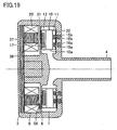
- Fig. 19 is a cross-sectional view showing yet another modification of this first embodiment, which is compared to Fig. 3 .
- yoke 19 is replaced with a yoke 36 and magnetic element 18 is replaced with a magnetic element 37.
- Yoke 36 and magnetic element 37 each include a plurality of steel plates stacked in a length direction of a rotation axis of impeller 10.
- eddy current loss that occurs in yoke 36 and magnetic element 37 can be reduced, thus increasing energy efficiency when impeller 10 is driven to rotate.
- a magnetic element 32 may be replaced with a magnetic element 38 including a plurality of steel plates stacked in a rotation direction of impeller 10.
- magnetic element 32 may be replaced with a magnetic element 39 including a plurality of steel plates stacked in a radial direction of impeller 10. The same effect as in the modification in Fig. 19 can be obtained also in these cases.
- each of yoke 19 and magnetic element 18 in Fig. 3 may be made of powders of pure iron, soft iron or ferrosilicon. In this case, iron loss in yoke 19 and magnetic element 18 can be reduced, thus increasing energy efficiency when impeller 10 is driven to rotate.
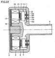
- Fig. 22 is a cross-sectional view showing yet another modification of this first embodiment, which is compared to Fig. 3 .
- magnetic element 18 has been removed.
- magnitude of a resultant force of attractive force F1 between permanent magnets 15a, 15b and permanent magnets 16a, 16b and attractive force F2 between permanent magnet 17 and yoke 19 is adjusted to zero at position P0 in the movable range of impeller 10 in blood chamber 7.
- the same effect as in the first embodiment can be obtained also in this modification.
- magnetic element 40 When attractive force F2 between permanent magnet 17 and yoke 19 is smaller than attractive force F1 between permanent magnets 15a, 15b and permanent magnets 16a, 16b, as shown in Fig. 23 , a magnetic element 40 is arranged at a position different from that of coils 20 and attractive force F3 of magnetic element 40 and permanent magnet 17 is added so that attractive force F1 is balanced with attractive force F2 + F3 substantially at the center in the movable range of impeller 10.
- magnetic element 40 may be a permanent magnet.
- a permanent magnet 41 may be arranged at a position in impeller 10 facing magnetic element 40 and attractive force F4 between magnetic element 40 and permanent magnet 41 may be added so that attractive force F1 is balanced with attractive force F2 + F3 + F4 substantially at the center in the movable range of impeller 10.
- magnetic element 41 may be a permanent magnet.
- permanent magnet 41 may be a magnetic element.
- Figs. 25 (a) and (b) are cross-sectional views showing yet another modification of this first embodiment, which are compared to Figs. 5 (a) and (b) .
- Fig. 22 (a) is a cross-sectional view along the line XXVA-XXVA in Fig. 22 (b).
- the N pole of permanent magnet 15a and the N pole of permanent magnet 15b are provided in directions opposite to each other, and the N pole of permanent magnet 16a and the N pole of permanent magnet 16b are provided in directions opposite to each other.
- the S pole of permanent magnet 15a faces the N pole of permanent magnet 16a and the N pole of permanent magnet 15b faces the S pole of permanent magnet 16b.
- the same effect as in the first embodiment can be obtained also in this modification.
- the invention of the subject application is applicable also to a sensorless drive type centrifugal blood pump apparatus without including magnetic sensor SE.
- phase information is found from a counterelectromotive force waveform and a current waveform generated in coil 20 as permanent magnet 17 rotates or change in inductance in coil 20, and a phase of a current fed to coil 20 is adjusted based on the phase information.
- magnitude of a d-axis current Id (excitation current) is varied while a q-axis current Iq (torque current) is maintained, so that an effect the same as that of phase adjustment can be obtained.
- Fig. 26 is a cross-sectional view showing a structure of a pump unit of a centrifugal blood pump apparatus according to a second embodiment of the present invention, which is compared to Fig. 3 .
- a plurality of (e.g., eight) permanent magnets 50 instead of the plurality of permanent magnets 17 are embedded in shroud 12 of impeller 10.
- the plurality of permanent magnets 50 are arranged at regular angular intervals along the same circle.
- a plurality of (e.g., eight) permanent magnets 51 for attracting the plurality of permanent magnets 50 are provided in motor chamber 8.
- the plurality of permanent magnets 51 are arranged at regular angular intervals along the same circle to face the plurality of permanent magnets 50 in impeller 10.
- the plurality of permanent magnets 51 are provided in a surface of a bowl-shaped rotor 52.
- a plurality of (e.g., eight) permanent magnets 53 are provided at regular angular intervals on an inner side of a circumference of rotor 52.
- the plurality of permanent magnets 53 are arranged at regular angular intervals along the same circle such that adjacent magnetic polarities thereof are different from each other.
- permanent magnet 53 having the N-pole toward the inside of rotor 52 and permanent magnet 53 having the S-pole toward the inside of rotor 52 are alternately arranged at regular angular intervals along the same circle.
- a central portion of rotor 52 is rotatably supported by a central axis 55 with a bearing 54 being interposed, and rotor 52 is rotatably provided along diaphragm 6.
- Central axis 55 is provided to stand in a center of a disc-shaped yoke 56.
- a plurality of (e.g., nine) magnetic elements 57 are provided at regular angular intervals around central axis 55 on the surface of yoke 56. Tip ends of the plurality of magnetic elements 57 are arranged along the same circle, as facing the plurality of permanent magnets 53 in rotor 52.
- a coil 58 is wound around each magnetic element 57.
- the plurality of permanent magnets 53, the plurality of magnetic elements 57, and a plurality of coils 58 constitute a motor for rotating rotor 52.
- Voltages are applied to nine coils 58 in a power distribution system shifted by 120 degrees, for example. Namely, nine coils 58 are divided into groups each including three coils. Voltages VU, VV and VW shown in Fig. 9 are applied to first to third coils 58 of each group, respectively.
- rotating magnetic field can be formed by applying voltages VU, VV and VW to first to third coils 58, respectively, and rotor 52 can be rotated by attractive force and repulsion force between the plurality of magnetic elements 57 and the plurality of permanent magnets 53 in rotor 52.
- impeller 10 rotates as a result of attractive force from the plurality of permanent magnets 51 in rotor 52 and the plurality of permanent magnets 50 in impeller 10.
- impeller 10 is readily levitated from housing 2 without contacting even when hydrodynamic pressure is small during low-speed rotation.
- a plurality of grooves for hydrodynamic bearing 21 are formed in the surface of diaphragm 6 facing shroud 12 of impeller 10, and a plurality of grooves for hydrodynamic bearing 22 are formed in the inner wall of blood chamber 7 facing shroud 11.
- attractive force F1 between permanent magnets 15a, 15b and permanent magnets 16a, 16b decreases as impeller 10 moves in the radial direction.
- attractive force F2 between permanent magnets 50 and 51 decreases as impeller 10 moves in the radial direction.
- impeller 10 is eccentric in the radial direction. Therefore, when amount of change ⁇ F1 in attractive force F1 with respect to an amount of eccentricity of impeller 10 is different from amount of change ⁇ F2 in attractive force F2 with respect to the amount of eccentricity of impeller 10, a levitation position of impeller 10 at that eccentric position is displaced from the central position in blood chamber 7. Therefore, any one gap of the gap between impeller 10 and the inner wall of blood chamber 7 and the gap between impeller 10 and diaphragm 6 becomes narrow, and impeller 10 is brought into contact with the inner wall of blood chamber 7 or with diaphragm 6 even by action of small disturbance on impeller 10.
- Figs. 27 (a) and (b) are diagrams showing a state of overlapping between permanent magnets 50 and 51 when impeller 10 is eccentric.
- Fig. 27 (a) shows a case where a diameter of permanent magnet 50, 51 is relatively large
- Fig. 27 (a) shows a case where a diameter of permanent magnet 50, 51 is relatively small.
- Fig. 28 is a diagram showing relation between an amount of eccentricity of impeller 10 and attractive force F2.
- a center of rotation of the plurality of permanent magnets 50 is denoted as O1
- a center of rotation of the plurality of permanent magnets 51 is denoted as 02.
- centers of rotation O1 and O2 match with each other when viewed in a direction perpendicular to impeller 10.
- centers of rotation O1 and O2 are displaced from each other by a certain distance d as a result of eccentricity of impeller 10.
- Attractive force F2 between the plurality of sets of permanent magnets 50 and 51 varies in accordance with the sum of the facing areas of the plurality of sets of permanent magnets 50 and 51. Therefore, as shown in Fig. 28 , attractive force F2 decreases with displacement of impeller 10 in the radial direction.
- An amount of displacement ⁇ F2A in attractive force F2 in a case where a diameter of permanent magnet 50, 51 is relatively large is smaller than an amount of displacement ⁇ F2B in attractive force F2 in a case where a diameter of permanent magnet 50, 51 is relatively small.
- an amount of displacement between a central point of permanent magnet 50 and a central point of permanent magnet 51 is the sum of an amount of eccentricity of impeller 10 and an amount of displacement in angle in a circumferential direction generated by desired rotational torque, and an amount of displacement between center of rotation O1 of permanent magnet 50 and center of rotation 02 of permanent magnet 51 is equal to the amount of eccentricity of impeller 10.
- an amount of displacement between the center of rotation of permanent magnets 15a, 15b and the center of rotation of permanent magnets 16a, 16b is equal to the amount of eccentricity of impeller 10.
- an absolute value K1 of a positive supporting rigidity value in the radial direction of the magnetic coupling portion constituted of permanent magnets 15a, 15b and permanent magnets 16a, 16b and an absolute value K2 of a positive supporting rigidity value in the radial direction of the magnetic coupling portion constituted of the plurality of sets of permanent magnets 50 and 51 desirably keep relation of K1-K2>0.
- relation of ⁇ F1 ⁇ ⁇ F2 is satisfied by adjusting a diameter of permanent magnet 50, 51 and by adjusting amount of change ⁇ F2 in attractive force F2.
- Relation of ⁇ F1 ⁇ ⁇ F2 may be satisfied, however, by adjusting a dimension of permanent magnets 15a, 15b and permanent magnets 16a, 16b (for example, a width, an interval in the radial direction) and by adjusting amount of change ⁇ F1 in attractive force F1.
- Figs. 29 (a) and (b) are diagrams showing a modification of the second embodiment and showing a state of overlapping between permanent magnets 15a, 15b and permanent magnets 16a, 16b when impeller 10 is eccentric.
- Fig. 27 (a) shows a case where magnetic poles of permanent magnets 15a, 15b (permanent magnets 16a, 16b) are oriented in the same direction, while Fig. 27 (b) shows a case where magnetic poles of permanent magnets 15a, 15b (permanent magnets 16a, 16b) are oriented in directions opposite to each other.
- Fig. 28 is a diagram showing relation between an amount of eccentricity of impeller 10 and attractive force F 1.
- a center of rotation of permanent magnets 15a, 15b is denoted as O1
- a center of rotation of permanent magnets 16a, 16b is denoted as 02.
- centers of rotation O1 and O2 match with each other when viewed in a direction perpendicular to impeller 10.
- centers of rotation O1 and O2 are displaced from each other by certain distance d as a result of eccentricity of impeller 10.
- magnetic poles of permanent magnets 15a, 15b and permanent magnets 16a, 16b are arranged as shown in Figs. 29 (a) and (b) or Figs. 29(c) and (d) , so that amount of change ⁇ F1 in attractive force F1 is adjusted and then amount of change ⁇ F2 in attractive force F2 is adjusted with the method shown in the second embodiment.
- the effect the same as in the second embodiment is obtained also in this modification.
Landscapes
- Engineering & Computer Science (AREA)
- Health & Medical Sciences (AREA)
- Mechanical Engineering (AREA)
- Heart & Thoracic Surgery (AREA)
- General Engineering & Computer Science (AREA)
- Life Sciences & Earth Sciences (AREA)
- Veterinary Medicine (AREA)
- Hematology (AREA)
- Anesthesiology (AREA)
- Animal Behavior & Ethology (AREA)
- General Health & Medical Sciences (AREA)
- Public Health (AREA)
- Biomedical Technology (AREA)
- Cardiology (AREA)
- Physics & Mathematics (AREA)
- Electromagnetism (AREA)
- Fluid Mechanics (AREA)
- External Artificial Organs (AREA)
- Structures Of Non-Positive Displacement Pumps (AREA)
Description
- The present invention relates to a centrifugal pump apparatus, and particularly to a centrifugal pump apparatus including an impeller for delivering liquid by centrifugal force during rotation.
- In recent years, a centrifugal blood pump apparatus in which driving torque from an external motor is transmitted to an impeller in a blood chamber through magnetic coupling has increasingly been used as a blood circulation apparatus of an artificial heart-lung machine. According to such a centrifugal blood pump apparatus, physical contact between the blood chamber and the outside can be eliminated, thus preventing invasion of bacteria and the like into blood.
- A centrifugal blood pump in PTL 1 (Japanese Patent Laying-Open No.
2004-209240 - A centrifugal blood pump in PTL 2 (Japanese Patent Laying-Open No.
2006-167173 - A turbo-type pump in
Figs. 8 and9 of PTL 3 (Japanese Patent Laying-Open No.4-91396 - A clean pump in PTL 4 (Japanese Utility Model Laying-Open No.
6-53790 - The electromagnet is actuated when a rotation speed of the impeller is lower than a prescribed rotation speed, and power supply to the electromagnet is stopped when the rotation speed of the impeller becomes higher than the prescribed rotation speed. Owing to attractive force acting on the one surface of the impeller from the second permanent magnet in the rotor and a hydrodynamic bearing effect of the groove for hydrodynamic bearing, the impeller moves away from an inner surface of the housing and rotates without contacting.
Furthermore, fromUS 2008/124231 A1 a sensorless magnetic bearing type blood pump apparatus is known which includes a blood pump and a control mechanism. The blood pump has electromagnets for rotating a rotating body in a non-contact condition, and a hydrodynamic bearing section for rotating the rotating body in a non-contact condition when operation of the electromagnets is stopped. The control mechanism includes a pulse width modulation type electromagnet driving unit, a carrier component measuring unit for measuring carrier components of voltage and current in the driving unit, a modulation factor calculating unit which calculates a modulation factor using the carrier wave data, and a bearing mode changing-over mechanism for effecting change-over from the magnetic bearing mode to the hydrodynamic bearing mode when the calculated modulation factor is outside a predetermined range and for returning to the magnetic bearing mode after the change-over. -
-
PTL 1; Japanese Patent Laying-Open No.2004-209240 - PTL 2: Japanese Patent Laying-Open No.
2006-167173 - PTL 3: Japanese Patent Laying-Open No.
4-91396 - PTL 4: Japanese Utility Model Laying-Open No.
6-53790 - The pumps in
PTLs 1 to 4 described above are common in the feature of axially (in a direction of a rotation axis of the impeller) supporting the impeller by the grooves for hydrodynamic bearing formed in a portion where the impeller and the housing face each other and radially (in a direction of a radius of the impeller) supporting the impeller by the attractive force between the permanent magnet provided in the impeller and the permanent magnet provided outside the housing. - In such a centrifugal pump apparatus, when rigidity for supporting the impeller (force required for moving the impeller by a unit length) is low, the impeller comes in contact with the inner wall of the blood chamber by application of vibration (accelerated vibration) involved with a user's operation. Therefore, supporting rigidity sufficiently high in each of the axial direction and the radial direction is required.
- In order to increase rigidity for supporting the impeller, magnetic coupling force between the permanent magnet in the impeller and the permanent magnet on the housing side should only be increased. It is not easy, however, to increase that magnetic coupling force. Namely, in a hydrodynamic bearing type centrifugal pump apparatus, initially, a flow rate, a pump head (pressure), and a minimum value of an interval between the blood chamber and the impeller are provided as the specifications. Then, a diameter of the impeller determines a rotation speed and a dimension of a groove for hydrodynamic bearing.
- When the dimension of the groove for hydrodynamic bearing, the diameter of the impeller, the rotation speed, and the interval between the blood chamber and the impeller are determined, a load capacity is determined and hence magnetic coupling force balanced therewith is determined. When magnetic coupling force is determined, rigidity for supporting the impeller is also determined. Therefore, though it is necessary to increase the load capacity in order to increase rigidity for supporting the impeller, increase in the load capacity is limited, because the load capacity is dependent on viscosity of blood, a rotation speed of the impeller, a dimension of a groove for hydrodynamic bearing, and an interval between the blood chamber and the impeller.
- In addition, a gap between an end surface of the impeller and an inner surface of the housing on which hydrodynamic pressure acts is formed on a side of an impeller rotational torque generation portion and on a side of an impeller auxiliary attracting portion. These gaps being substantially equal to each other means a greatest distance between the end surface of the impeller and the inner surface of the housing. Thus, even when disturbance force acts on the impeller, it is less likely that the end surface of the impeller comes in contact with the inner surface of the housing. In a single volute pump construction or a pump construction where there is no volute and a blood outlet port is arranged in contact with a cylindrical housing, however, unbalance in pressure in a pump chamber is caused during a desired pump operation and the impeller moves in a radial direction in such a manner that it is attracted toward the blood outlet port. Then, attractive force in the axial direction at both end surfaces of the impeller becomes smaller.
- Therefore, when an amount of change in attractive force in the axial direction with respect to displacement in the radial direction of the impeller rotational torque generation portion is different from an amount of change in attractive force in the axial direction with respect to displacement in the radial direction of a magnetic coupling portion formed in the impeller auxiliary attracting portion, a position where attractive forces in the axial direction are balanced with each other is displaced from the substantially central position in the housing during the desired pump operation. Consequently, one of the gaps between the end surface of the impeller and the inner surface of the housing on both sides becomes narrower and the other of them becomes wider. On the side where the gap has become narrower, even small disturbance force acting on the impeller readily causes contact between the end surface of the impeller and the inner surface of the housing.
- In view of the above, a main object of the present invention is to provide a centrifugal pump apparatus having resistance to disturbance acting on an impeller, in which a gap for levitation between the impeller and a housing is not varied even when the impeller radially moves in the housing.
- A centrifugal pump apparatus according to the present invention is a centrifugal pump apparatus including a housing having first and second chambers partitioned from each other by a diaphragm, an impeller rotatably provided in the first chamber along the diaphragm, for delivering liquid by centrifugal force during rotation, and drive means provided in the second chamber for driving the impeller to rotate with the diaphragm being interposed, and it includes a first magnetic element provided in one surface of the impeller, a second magnetic element provided in an inner wall of the first chamber facing the one surface of the impeller, for attracting the first magnetic element, and a third magnetic element provided in the other surface of the impeller. During rotation of the impeller, first attractive force between the first and second magnetic elements and second attractive force between the third magnetic element and the drive means are balanced with each other substantially in a center of a movable range of the impeller in the first chamber. An amount of change in the first attractive force with respect to an amount of eccentricity in a radial direction of the impeller is substantially equal to an amount of change in the second attractive force with respect to the amount of eccentricity in the radial direction of the impeller. A first groove for hydrodynamic bearing is formed in the one surface of the impeller or in the inner wall of the first chamber facing the one surface, and a second groove for hydrodynamic bearing is formed in the other surface of the impeller or in the diaphragm facing the other surface. The third magnetic element includes a plurality of magnets arranged along the same circle such that adjacent magnetic polarities are different from each other, and the drive means includes a plurality of coils provided to face the plurality of magnets, for generating rotating magnetic field. Furthermore, the second attractive force is adjusted by varying a phase of a current fed to the plurality of coils.
- Preferably, the drive means includes a rotor rotatably provided along the diaphragm in the second chamber, a fourth magnetic element provided in the rotor, for attracting the third magnetic element, and a motor for rotating the rotor.
- Further preferably, an absolute value of a positive supporting rigidity value in the radial direction of a magnetic coupling portion constituted of the first and second magnetic elements is greater than an absolute value of a positive supporting rigidity value in a radial direction of a magnetic coupling portion constituted of the third and fourth magnetic elements.
- Further preferably, the third magnetic element includes a plurality of magnets arranged along the same circle such that adjacent magnetic polarities are different from each other. The drive means includes a plurality of fourth magnetic elements provided to face the plurality of magnets and a plurality of coils provided in correspondence with the plurality of fourth magnetic elements respectively and each wound around the corresponding fourth magnetic element, for generating rotating magnetic field.
- Further preferably, the centrifugal pump apparatus further includes a magnetic sensor provided in the second chamber to face the plurality of magnets, and a phase of a current fed to the plurality of coils is varied based on an output signal from the magnetic sensor.
- Further preferably, the centrifugal pump apparatus further includes a plurality of the first magnetic elements provided in one surface of the impeller and aligned in a radial direction of the impeller and a plurality of the second magnetic elements provided in the inner wall of the first chamber facing the one surface of the impeller and attracting the plurality of first magnetic elements respectively. During rotation of the impeller, first attractive force between the plurality of first magnetic elements and the plurality of second magnetic elements and second attractive force between the third magnetic element and the drive unit are balanced with each other substantially in the center of the movable range of the impeller in the first chamber.
- Further preferably, at least one magnetic element of the plurality of first magnetic elements and the plurality of second magnetic elements is formed annularly around a rotation centerline of the impeller.
- Further preferably, at least one magnetic element of the plurality of first magnetic elements and the plurality of second magnetic elements are formed as multiple pieces annularly around a rotation centerline of the impeller.
- Further preferably, each of the plurality of first magnetic elements and the plurality of second magnetic elements is a permanent magnet, and N poles of two first magnetic elements adjacent in the radial direction of the impeller are oriented in an identical direction.
- Further preferably, each of the plurality of first magnetic elements and the plurality of second magnetic elements is a permanent magnet, and N poles of two first magnetic elements adjacent in the radial direction of the impeller are oriented in directions different from each other.
- Further preferably, an interval between two first magnetic elements adjacent in the radial direction of the impeller is greater than 1/2 of a movable distance of the impeller in the radial direction in the first chamber. In this case, even when the impeller moves in the radial direction to a maximum extent, magnetic interference between two adjacent pairs of first and second magnetic elements can be avoided.
- Further preferably, a plurality of the third magnetic elements are provided, and the plurality of third magnetic elements are arranged along the same circle such that adjacent magnetic polarities are different from each other. The drive means includes a plurality of coils provided in correspondence with the plurality of third magnetic elements respectively, for generating rotating magnetic field.
- Further preferably, a plurality of the third magnetic elements are provided, and the plurality of third magnetic elements are arranged along the same circle such that adjacent magnetic polarities are different from each other. The drive means includes a plurality of fourth magnetic elements arranged to face the plurality of third magnetic elements and a plurality of coils provided in correspondence with the plurality of fourth magnetic elements respectively and each wound around the corresponding fourth magnetic element, for generating rotating magnetic field.
- Further preferably, the drive means includes a rotor rotatably provided along the diaphragm in the second chamber, a fourth magnetic element provided in the rotor to face the third magnetic element, for attracting the third magnetic element, and a motor for rotating the rotor.
- Further preferably, the liquid is blood and the centrifugal pump apparatus is used for circulating the blood. In this case, the impeller is smoothly activated to rotate and a distance between the impeller and the housing is secured, thereby preventing occurrence of hemolysis.
- In the centrifugal pump apparatus according to the present invention, first and second attractive forces acting on the impeller are balanced with each other substantially in the center of the movable range of the impeller, amounts of change in the first and second attractive forces with respect to an amount of eccentricity in the radial direction of the impeller are made substantially equal to each other, and first and second grooves for hydrodynamic bearing are formed. Therefore, even when the impeller moves in the radial direction in the housing, a gap for levitation between the impeller and the housing is not varied and thus resistance to disturbance acting on the impeller can be improved.
-
-
Fig. 1 is a front view showing the appearance of a pump unit of a centrifugal blood pump apparatus according to a first embodiment of the present invention. -
Fig. 2 is a side view of the pump unit shown inFig. 1 . -
Fig. 3 is a cross-sectional view along the line III-III inFig. 2 . -
Fig. 4 is a cross-sectional view along the line IV-IV inFig. 3 . -
Fig. 5 is a diagram showing a permanent magnet shown inFig. 3 . -
Fig. 6 is a cross-sectional view showing a state where an impeller has been removed from the cross-sectional view along the line IV-IV inFig. 3 . -
Fig. 7 is a cross-sectional view showing the state where the impeller has been removed from a cross-sectional view along the line VII-VII inFig. 3 . -
Fig. 8 is a cross-sectional view along the line VIII-VIII inFig. 3 . -
Fig. 9 is a time chart showing an operation of a magnetic sensor shown inFig. 8 . -
Fig. 10 is a time chart illustrating voltages applied to a plurality of coils shown inFig. 8 . -
Fig. 11 is a diagram showing relation between a levitation position of the impeller and force acting on the impeller. -
Fig. 12 is another diagram showing relation between a levitation position of the impeller and force acting on the impeller. -
Fig. 13 is a diagram showing relation between an amount of eccentricity in a radial direction of the impeller and force acting on the impeller. -
Fig. 14 is a block diagram showing a configuration of a controller for controlling the pump unit shown inFigs. 1 to 8 . -
Fig. 15 is a cross-sectional view showing a modification of this first embodiment. -
Fig. 16 is a cross-sectional view showing another modification of this first embodiment. -
Fig. 17 is a cross-sectional view showing yet another modification of the first embodiment. -
Fig. 18 is a cross-sectional view showing yet another modification of the first embodiment. -
Fig. 19 is a cross-sectional view showing yet another modification of the first embodiment. -
Fig. 20 is a cross-sectional view showing yet another modification of the first embodiment. -
Fig. 21 is a cross-sectional view showing yet another modification of the first embodiment. -
Fig. 22 is a cross-sectional view showing yet another modification of the first embodiment. -
Fig. 23 is a cross-sectional view showing yet another modification of the first embodiment. -
Fig. 24 is a cross-sectional view showing yet another modification of the first embodiment. -
Fig. 25 is a diagram showing yet another modification of the first embodiment. -
Fig. 26 is a cross-sectional view showing a structure of a pump unit of a centrifugal blood pump apparatus according to a second embodiment of the present invention. -
Fig. 27 is a diagram for illustrating relation between a diameter of apermanent magnet Fig. 26 and eccentricity of the impeller. -
Fig. 28 is a diagram showing relation between attractive force F2 betweenpermanent magnets Fig. 27 and an amount of eccentricity of the impeller. -
Fig. 29 is a diagram showing a modification of the second embodiment. -
Fig. 30 is a diagram showing relation between attractive force F1 betweenpermanent magnets permanent magnets Fig. 29 and an amount of eccentricity of the impeller. - As shown in
Figs. 1 and2 , apump unit 1 of a centrifugal blood pump apparatus according to a first embodiment includes ahousing 2 made of a nonmagnetic material.Housing 2 includes acylindrical body portion 3, a cylindricalblood inlet port 4 provided to stand at a center of one end surface ofbody portion 3, and a cylindricalblood outlet port 5 provided on an outer circumferential surface ofbody portion 3.Blood outlet port 5 extends in a tangential direction of the outer circumferential surface ofbody portion 3. - In
housing 2, as shown inFig. 3 , ablood chamber 7 and amotor chamber 8 partitioned from each other by adiaphragm 6 are provided. Inblood chamber 7, as shown inFigs. 3 and4 , a disc-shapedimpeller 10 having a throughhole 10a in a center thereof is rotatably provided.Impeller 10 includes twoshrouds vanes 13 formed between twoshrouds Shroud 11 is arranged on theblood inlet port 4 side andshroud 12 is arranged on thediaphragm 6 side.Shrouds vanes 13 are made of a nonmagnetic material. - A plurality of (six in this case)
blood passages 14 partitioned from one another by the plurality ofvanes 13 are formed between twoshrouds Fig. 4 ,blood passage 14 is in communication with throughhole 10a in the center ofimpeller 10, and it extends with throughhole 10a inimpeller 10 as a starting point to an outer circumference such thatblood passage 14 gradually increases in width. In other words,vane 13 is formed between twoadjacent blood passages 14. In the first embodiment, the plurality ofvanes 13 are formed at regular angular intervals, and they have the same shape. Thus, the plurality ofblood passages 14 are provided at regular angular intervals and they have the same shape. - When
impeller 10 is driven to rotate, blood that has flowed in throughblood inlet port 4 is delivered by centrifugal force from throughhole 10a to an outer circumferential portion ofimpeller 10 viablood passages 14 and it flows out throughblood outlet port 5. -
Permanent magnets shroud 11 andpermanent magnets permanent magnets blood chamber 7 facingshroud 11.Permanent magnets impeller 10 to the side opposite tomotor chamber 8, that is, towardblood inlet port 4. -
Figs. 5 (a) and (b) are diagrams showing a structure ofpermanent magnets Fig. 5 (a) is a cross-sectional view along the line VA-VA inFig. 5 (b) . As shown inFigs. 5 (a) and (b) , each ofpermanent magnets permanent magnet 15a is smaller than an inner diameter ofpermanent magnet 15b.Permanent magnets permanent magnets impeller 10. Though end surfaces of respectivepermanent magnets - On the other hand, each of
permanent magnets impeller 10. An outer diameter and an inner diameter of twopermanent magnets 16a arranged annularly are the same as the outer diameter and the inner diameter ofpermanent magnet 15a, respectively. An outer diameter and an inner diameter of twopermanent magnets 16b arranged annularly are the same as the outer diameter and the inner diameter ofpermanent magnet 15b, respectively. Though end surfaces of respectivepermanent magnets Permanent magnets permanent magnets - In addition, as shown in
Fig. 3 , an interval betweenpermanent magnets permanent magnets impeller 10 in the radial direction (that is, a distance of a difference between the inner diameter ofblood chamber 7 and the outer diameter of impeller 10) (D1>D2). This is because, whenimpeller 10 moves in the radial direction to a maximum extent while relation of D1< D2 is satisfied,permanent magnets permanent magnets impeller 10 to a central position of the pump becomes unstable. - Since two pairs of
permanent magnets permanent magnets impeller 10, rigidity for supportingimpeller 10 in the radial direction can be increased as compared with a case where only a pair of permanent magnets is provided in the radial direction ofimpeller 10. - Instead of providing
permanent magnets permanent magnets shroud 11 and the inner wall ofblood chamber 7, respectively, a permanent magnet may be provided in one ofshroud 11 and the inner wall ofblood chamber 7, and a magnetic element may be provided in the other. Either a soft magnetic element or a hard magnetic element may be used as the magnetic element. - Though
Fig. 3 shows a case where opposing surfaces ofpermanent magnets permanent magnets impeller 10 due to attractive force ofpermanent magnets permanent magnets permanent magnets permanent magnets permanent magnets permanent magnets impeller 10 can be prevented. - In
Figs. 5 (a) and (b) , each ofpermanent magnets permanent magnets impeller 10. In contrast, however, each ofpermanent magnets permanent magnets impeller 10. Alternatively, each ofpermanent magnets permanent magnets impeller 10. - As shown in
Figs. 3 and4 , a plurality of (e.g., eight)permanent magnets 17 are embedded inshroud 12. The plurality ofpermanent magnets 17 are arranged at regular angular intervals along the same circle such that adjacent magnetic polarities thereof are different from each other. In other words,permanent magnet 17 having the N-pole towardmotor chamber 8 andpermanent magnet 17 having the S-pole towardmotor chamber 8 are alternately arranged at regular angular intervals along the same circle. - As shown in
Figs. 3 and8 , a plurality of (e.g., nine)magnetic elements 18 are provided inmotor chamber 8. The plurality ofmagnetic elements 18 are arranged at regular angular intervals along the same circle to face the plurality ofpermanent magnets 17 inimpeller 10. A base end of each of the plurality ofmagnetic elements 18 is joined to one disc-shapedyoke 19. Acoil 20 is wound around eachmagnetic element 18. - Three magnetic sensors SE are provided among four adjacent
magnetic elements 18 among ninemagnetic elements 18. Three magnetic sensors SE are arranged to face paths inimpeller 10, through which the plurality ofpermanent magnets 17 pass. Asimpeller 10 rotates and the S pole and the N pole of the plurality ofpermanent magnets 17 alternately pass by the vicinity of magnetic sensor SE, a level of an output signal from magnetic sensor SE varies sinusoidally as shown inFig. 9 . Therefore, by detecting temporal change in the output signal from magnetic sensor SE, positional relation between the plurality ofpermanent magnets 17 and the plurality ofmagnetic elements 18 can be detected and timing to feed a current to the plurality ofcoils 20 and the rotation speed ofimpeller 10 can be found. - When a gap between
impeller 10 anddiaphragm 6 is wide, magnetic field in the vicinity of magnetic sensor SE becomes weak and an amplitude A1 of the output signal from magnetic sensor SE becomes small. When the gap betweenimpeller 10 anddiaphragm 6 is narrow, magnetic field in the vicinity of magnetic sensor SE becomes strong and an amplitude A2 of the output signal from magnetic sensor SE becomes great. Therefore, by detecting an amplitude of the output signal from magnetic sensor SE, a position ofimpeller 10 in the movable range ofimpeller 10 can be detected. - Voltages are applied to nine
coils 20 in a power distribution system shifted by 120 degrees, for example. That is, ninecoils 20 are divided into groups each including three coils. Voltages VU, VV and VW as shown inFig. 10 are applied to first tothird coils 20 of each group, respectively. Tofirst coil 20, a positive voltage is applied during a period of 0 to 120 degrees, 0 V is applied during a period of 120 to 180 degrees, a negative voltage is applied during a period of 180 to 300 degrees, and 0 V is applied during a period of 300 to 360 degrees. Accordingly, a tip surface ofmagnetic element 18 havingfirst coil 20 wound therearound (end surface on theimpeller 10 side) becomes the N-pole during the period of 0 to 120 degrees and becomes the S-pole during the period of 180 to 300 degrees. Voltage VV is delayed in phase from voltage VU by 120 degrees, and voltage VW is delayed in phase from voltage VV by 120 degrees. Thus, rotating magnetic field can be formed by applying voltages VU, VV and VW to first tothird coils 20, respectively, so thatimpeller 10 can be rotated by attractive force and repulsion force between the plurality ofmagnetic elements 18 and the plurality ofpermanent magnets 17 inimpeller 10. - When
impeller 10 is rotating at a rated rotation speed, attractive force betweenpermanent magnets permanent magnets permanent magnets 17 and the plurality ofmagnetic elements 18 are set to be balanced with each other substantially around a center of a movable range ofimpeller 10 inblood chamber 7. Thus, force acting onimpeller 10 due to the attractive force is very small throughout the movable range ofimpeller 10. Consequently, frictional resistance during relative slide betweenimpeller 10 andhousing 2 which occurs whenimpeller 10 is activated to rotate can be lowered. In addition, a surface ofimpeller 10 and a surface of an inner wall ofhousing 2 are not damaged (no projections and recesses in the surfaces) during the relative slide, and moreover,impeller 10 is readily levitated fromhousing 2 without contacting even when hydrodynamic pressure is low during low-speed rotation. Accordingly, occurrence of hemolysis due to the relative slide betweenimpeller 10 andhousing 2 or occurrence of thrombus due to small damage (projections and recesses) to the surfaces which occurs during the relative slide is avoided. - A plurality of grooves for
hydrodynamic bearing 21 are formed in a surface ofdiaphragm 6 facingshroud 12 ofimpeller 10, and a plurality of grooves forhydrodynamic bearing 22 are formed in the inner wall ofblood chamber 7 facingshroud 11. When a rotation speed ofimpeller 10 becomes higher than a prescribed rotation speed, a hydrodynamic bearing effect is produced between each of grooves forhydrodynamic bearing impeller 10. As a result, drag is generated onimpeller 10 from each of grooves forhydrodynamic bearing impeller 10 to rotate without contacting inblood chamber 7. - Specifically, as shown in
Fig. 6 , the plurality of grooves forhydrodynamic bearing 21 are each formed with a size corresponding toshroud 12 ofimpeller 10. Each of grooves forhydrodynamic bearing 21 has one end on an edge (circumference) of a circular portion slightly distant from a center ofdiaphragm 6, and extends spirally (in other words, in a curved manner) toward a portion near an outer edge ofdiaphragm 6 such that groove forhydrodynamic bearing 21 gradually increases in width. The plurality of grooves forhydrodynamic bearing 21 have substantially the same shape, and they are arranged at substantially regular intervals. Groove forhydrodynamic bearing 21 is a concave portion, and it preferably has a depth of about 0.005 to 0.4 mm. It is preferable that about 6 to 36 grooves forhydrodynamic bearing 21 be provided. - In
Fig. 6 , ten grooves forhydrodynamic bearing 21 are arranged equiangularly with respect to a central axis ofimpeller 10. Since groove forhydrodynamic bearing 21 has a so-called inward spiral groove shape, clockwise rotation ofimpeller 10 causes increase in liquid pressure from an outer diameter portion toward an inner diameter portion of groove forhydrodynamic bearing 21. As a result, repulsion force is generated betweenimpeller 10 anddiaphragm 6 and it acts as hydrodynamic pressure. - In this manner, owing to the hydrodynamic bearing effect produced between
impeller 10 and the plurality of grooves forhydrodynamic bearing 21,impeller 10 moves away fromdiaphragm 6 and rotates without contacting. Accordingly, a blood flow path is secured betweenimpeller 10 anddiaphragm 6, thus preventing occurrence of blood accumulation therebetween and the resultant thrombus. Further, in a normal state, grooves forhydrodynamic bearing 21 perform a stirring function betweenimpeller 10 anddiaphragm 6, thus preventing occurrence of partial blood accumulation therebetween. - Instead of providing grooves for
hydrodynamic bearing 21 indiaphragm 6, grooves forhydrodynamic bearing 21 may be provided in a surface ofshroud 12 ofimpeller 10. - It is preferable that a corner portion of groove for
hydrodynamic bearing 21 be rounded to have R of at least 0.05 mm. As a result, occurrence of hemolysis can further be lessened. - As with the plurality of grooves for
hydrodynamic bearing 21, as shown inFig. 7 , the plurality of grooves forhydrodynamic bearing 22 are formed with a size corresponding toshroud 11 ofimpeller 10. Each of grooves forhydrodynamic bearing 22 has one end on the edge (circumference) of the circular portion slightly distant from the center of the inner wall ofblood chamber 7, and extends spirally (in other words, in a curved manner) toward the portion near the outer edge of the inner wall ofblood chamber 7 such that groove forhydrodynamic bearing 22 gradually increases in width. The plurality of grooves forhydrodynamic bearing 22 have substantially the same shape and they are arranged at substantially regular intervals. Groove forhydrodynamic bearing 22 is a concave portion and it preferably has a depth of about 0.005 to 0.4 mm. It is preferable that about 6 to 36 grooves forhydrodynamic bearing 22 be provided. InFig. 7 , ten grooves forhydrodynamic bearing 22 are equiangularly arranged with respect to the central axis ofimpeller 10. - Owing to the hydrodynamic bearing effect produced between
impeller 10 and the plurality of grooves forhydrodynamic bearing 22,impeller 10 moves away from the inner wall ofblood chamber 7 and rotates without contacting. In addition, whenpump unit 1 is subjected to external impact or when the hydrodynamic pressure generated by grooves forhydrodynamic bearing 21 becomes excessive,impeller 10 can be prevented from being in close contact with the inner wall ofblood chamber 7. The hydrodynamic pressure generated by grooves forhydrodynamic bearing 21 may be different from the hydrodynamic pressure generated by grooves forhydrodynamic bearing 22. - Grooves for
hydrodynamic bearing 22 may be provided in a surface ofshroud 11 ofimpeller 10, rather than on the inner surface side ofblood chamber 7. It is preferable that a comer portion of groove forhydrodynamic bearing 22 be rounded to have R of at least 0.05 mm. As a result, occurrence of hemolysis can further be lessened. - It is preferable that
impeller 10 rotate in a state where a gap betweenshroud 12 ofimpeller 10 anddiaphragm 6 is substantially equal to a gap betweenshroud 11 ofimpeller 10 and the inner wall ofblood chamber 7. If one of the gaps becomes narrower due to serious disturbance such as hydrodynamic force acting onimpeller 10, it is preferable that grooves forhydrodynamic bearing - While both of grooves for
hydrodynamic bearing Figs. 6 and7 , grooves forhydrodynamic bearing hydrodynamic bearing -
Fig. 11 is a diagram showing forces acting onimpeller 10 when magnitude of a resultant force of an attractive force F1 betweenpermanent magnets permanent magnets Fig. 11 ) and an attractive force F2 betweenpermanent magnet 17 andmagnetic element 18 is adjusted to zero at a position P1 other than a central position of the movable range ofimpeller 10 inblood chamber 7. The rotation speed ofimpeller 10 is kept at a rated value. - Namely, it is assumed that attractive force F1 between
permanent magnets permanent magnets permanent magnet 17 andmagnetic element 18 and a levitation position ofimpeller 10 where their resultant force becomes zero is on thediaphragm 6 side relative to the center of the movable range of the impeller. Grooves forhydrodynamic bearing - A horizontal axis of
Fig. 11 represents a position of impeller 10 (the left side in the figure being thediaphragm 6 side) and a vertical axis represents forces acting onimpeller 10. Force acting onimpeller 10 toward thediaphragm 6 side is expressed as a negative acting force. As the forces acting onimpeller 10, attractive force F1 betweenpermanent magnets permanent magnets permanent magnet 17 andmagnetic element 18, a hydrodynamic pressure F3 generated by grooves forhydrodynamic bearing 21, a hydrodynamic pressure F4 generated by grooves forhydrodynamic bearing 22, and "net force F5 acting on impeller," which is their resultant force, are illustrated. - As can be seen in
Fig. 11 , at a position where net force F5 acting onimpeller 10 becomes zero, the levitation position ofimpeller 10 is significantly deviated from the central position of the movable range ofimpeller 10. As a result, a distance between rotatingimpeller 10 anddiaphragm 6 becomes narrower, andimpeller 10 comes in contact withdiaphragm 6 even by the action of small disturbance force onimpeller 10. - In contrast,
Fig. 12 is a diagram showing forces acting onimpeller 10 when magnitude of the resultant force of attractive force F1 betweenpermanent magnets permanent magnets permanent magnet 17 andmagnetic element 18 is adjusted to zero at a central position P0 of the movable range ofimpeller 10 inblood chamber 7. The rotation speed ofimpeller 10 is kept at the rated value also in this case. - Namely, attractive force F1 between
permanent magnets permanent magnets permanent magnet 17 andmagnetic element 18 are set to be substantially equal to each other. In addition, grooves forhydrodynamic bearing impeller 10 is zero at the center of the movable range,impeller 10 is levitated at the central position when disturbance force is not acting onimpeller 10. - As such, a levitation position of
impeller 10 is determined by balance among attractive force F1 betweenpermanent magnets permanent magnets permanent magnet 17 andmagnetic element 18, and hydrodynamic pressures F3, F4 generated by grooves forhydrodynamic bearing impeller 10. By making F1 and F2 substantially equal to each other and by forming grooves forhydrodynamic bearing impeller 10 can be levitated substantially in a central portion ofblood chamber 7 during rotation ofimpeller 10. Sinceimpeller 10 has such a shape that vanes are formed between two discs as shown inFigs. 3 and4 , two surfaces facing the inner wall ofhousing 2 can be formed to have the same shape and the same dimensions. Therefore, it is possible to provide grooves forhydrodynamic bearing impeller 10. - In this case,
impeller 10 is levitated at the central position ofblood chamber 7 and thus held at a position farthest from the inner wall ofhousing 2. As a result, even if the levitation position ofimpeller 10 is changed due to application of disturbance force to levitatedimpeller 10, the possibility thatimpeller 10 is brought into contact with the inner wall ofhousing 2 is lowered, thus also lowering the possibility of occurrence of thrombus and hemolysis resulting from such contact. - While grooves for
hydrodynamic bearing Figs. 11 and12 , grooves forhydrodynamic bearing 21 may be different in shape and hydrodynamic pressure generating function from grooves forhydrodynamic bearing 22. For example, when disturbance acts onimpeller 10 always in one direction due to hydrodynamic force or the like during pumping, performance of a groove for hydrodynamic bearing in the disturbance direction may be made higher than performance of the other groove for hydrodynamic bearing, thereby levitating androtating impeller 10 at the central position ofhousing 2. As a result, the probability of contact betweenimpeller 10 andhousing 2 can be lowered, thereby attaining stable levitation performance ofimpeller 10. - Furthermore, when an absolute value of a negative axial supporting rigidity value of
impeller 10 which is constituted of attractive force F1 betweenpermanent magnets permanent magnets permanent magnet 17 andmagnetic element 18 is expressed as Ka, an absolute value of a positive radial rigidity value is expressed as Kr, and an absolute value of a positive rigidity value obtained by two grooves forhydrodynamic bearing impeller 10 rotates is expressed as Kg, it is preferable that relation of Kg > Ka + Kr be satisfied. - Specifically, when absolute value Ka of the negative axial rigidity value is 20000 N/m and absolute value Kr of the positive radial rigidity value is 10000 N/m, absolute value Kg of the positive rigidity value obtained by two grooves for
hydrodynamic bearing impeller 10 normally rotates is set to a value higher than 30000 N/m. - The axial supporting rigidity for
impeller 10 is a value obtained by subtracting negative rigidity due to the attractive force between the magnetic elements and the like from rigidity resulting from the hydrodynamic pressure generated by grooves forhydrodynamic bearing impeller 10 can be made higher than the radial supporting rigidity. With such setting, movement ofimpeller 10 can be suppressed more in the axial direction than in the radial direction when disturbance force acts onimpeller 10, thereby avoiding mechanical contact betweenimpeller 10 andhousing 2 in a portion where grooves forhydrodynamic bearing 21 are formed. - In particular, since grooves for
hydrodynamic bearing Figs. 3 ,6 and7 , mechanical contact betweenhousing 2 andimpeller 10 in these portions during rotation ofimpeller 10 may result in damage to one or both of a surface ofimpeller 10 and a surface of the inner wall of housing 2 (projections and recesses in the surfaces), and blood passage through this portion may cause occurrence of thrombus and hemolysis. In order to prevent mechanical contact at grooves forhydrodynamic bearing - Whirl occurs in
unbalanced impeller 10 during rotation, and this whirl is greatest when a natural frequency determined by the mass ofimpeller 10 and the supporting rigidity value ofimpeller 10 matches the rotation speed ofimpeller 10. - Since the radial supporting rigidity for
impeller 10 is smaller than the axial supporting rigidity inpump unit 1, it is preferable to set a maximum rotation speed ofimpeller 10 to be equal to or lower than the radial natural frequency. Accordingly, in order to prevent mechanical contact betweenimpeller 10 andhousing 2, when a radial rigidity value ofimpeller 10 which is constituted of attractive force F1 betweenpermanent magnets permanent magnets permanent magnet 17 andmagnetic element 18 is expressed as Kr (N/m), the mass ofimpeller 10 is expressed as m (kg), and the rotation speed of the impeller is expressed as ω (rad/s), it is preferable that relation of ω<(Kr/m)0.5 be satisfied. - Specifically, when the mass of
impeller 10 is 0.03 kg and the radial rigidity value is 2000 N/m, the maximum rotation speed ofimpeller 10 is set to 258 rad/s (2465 rpm) or lower. Conversely, when the maximum rotation speed ofimpeller 10 is set to 366 rad/s (3500 rpm), the radial rigidity is set to 5018 N/m or higher. - It is further preferable to set the maximum rotation speed of
impeller 10 to 80 % or lower of this ω. Specifically, when the mass ofimpeller 10 is 0.03 kg and the radial rigidity value is 2000 N/m, the maximum rotation speed is set to 206.4 rad/s (1971 rpm) or lower. Conversely, when it is desired to set the maximum rotation speed ofimpeller 10 to 366 rad/s (3500 rpm), the radial rigidity value is set to 6279 N/m or higher. By thus setting the maximum rotation speed ofimpeller 10, contact between rotatingimpeller 10 andhousing 2 can be suppressed. - In addition, as shown in
Fig. 13 , attractive force F1 betweenpermanent magnets permanent magnets Fig. 13 ) decreases with movement ofimpeller 10 in the radial direction. Similarly, attractive force F2 betweenpermanent magnet 17 andmagnetic element 18 decreases with movement ofimpeller 10 in the radial direction. - During a desired pump operation,
impeller 10 is eccentric in the radial direction. Therefore, when an amount of change ΔF1 in attractive force F1 with respect to an amount of eccentricity ofimpeller 10 is different from an amount of change ΔF2 in attractive force F2 with respect to the amount of eccentricity ofimpeller 10, a levitation position ofimpeller 10 at that eccentric position is displaced from the central position inblood chamber 7. Therefore, if any one gap of the gap betweenimpeller 10 and the inner wall ofblood chamber 7 and the gap betweenimpeller 10 anddiaphragm 6 becomes narrow,impeller 10 is brought into contact with the inner wall ofblood chamber 7 or withdiaphragm 6 even by action of small disturbance onimpeller 10. - On the other hand, in a case where amount of change ΔF1 in attractive force F1 is equal to amount of change ΔF2 in attractive force F2, even though
impeller 10 is eccentric in the radial direction, a levitation position ofimpeller 10 is maintained at a central position inblood chamber 7. Therefore, even when disturbance acts onimpeller 10, it is less likely thatimpeller 10 comes in contact with the inner wall ofblood chamber 7 ordiaphragm 6. Then, in this first embodiment, by adjusting a phase of a current to be fed tocoil 20, relation of ΔF1 ≈ ΔF2 is satisfied. Thus, even whenimpeller 10 is eccentric in the radial direction, a levitation position ofimpeller 10 in the axial direction is kept at the central position inblood chamber 7. -
Fig. 14 is a block diagram showing a configuration of acontroller 25 for controllingpump unit 1. InFig. 14 ,controller 25 includes anamplitude operation unit 26, acomparator 27, astorage unit 28, amotor control circuit 29, and apower amplifier 30.Amplitude operation unit 26 operates an amplitude of an output signal from magnetic sensor SE, operates a levitation position ofimpeller 10 based on the amplitude, and provides a signal indicating the levitation position ofimpeller 10 tomotor control circuit 29.Comparator 27 compares magnitude of output signals from three magnetic sensors SE and a reference voltage, detects a status of rotation ofpermanent magnet 17 based on a result of comparison, and provides a rotational drive signal indicating a status of rotation ofpermanent magnet 17 tomotor control circuit 29.Storage unit 28 stores waveforms of output signals fromamplitude operation unit 26 andcomparator 27 whileimpeller 10 rotates at the central position in the movable range at a prescribed rotation speed. -
Motor control circuit 29 outputs three-phase control signals in the power distribution system shifted by 120 degrees, for example, such that waveforms of the output signals fromamplitude operation unit 26 andcomparator 27 match waveforms stored instorage unit 28.Power amplifier 27 amplifies the three-phase control signals frommotor control circuit 29 and generates three-phase voltages VU, VV and VW shown inFig. 10 . Three-phase voltages VU, VV and VW are applied to first tothird coils 20 described with reference toFigs. 8 to 10 , respectively. As a result, three-phase AC currents flow through first tothird coils 20 andimpeller 10 rotates at a prescribed rotation speed at the central position of the movable range. - As
impeller 10 is eccentric in the radial direction, attractive forces F1, F2 decrease, however, a load current is increased in order to perform a desired pump operation, and hence attractive force F2 increases. Adjustment of attractive force F2 is made by adjusting a phase of a current fed tocoil 20. - Namely, when a phase difference between three-phase voltages VU, VV, VW and the output signals from three magnetic sensors SE is at a prescribed value, efficiency is maximized. As phases of three-phase voltages VU, VV, VW are advanced with respect to phases of the output signals from three magnetic sensors SE, attractive force F2 between
permanent magnet 17 andmagnetic element 18 decreases. In contrast, as phases of three-phase voltages VU, VV, VW are delayed with respect to phases of the output signals from three magnetic sensors SE, attractive force F2 betweenpermanent magnet 17 andmagnetic element 18 increases. - Therefore, when
impeller 10 is eccentric in the radial direction and the levitation position ofimpeller 10 in the axial direction is displaced from the central position inblood chamber 7, the levitation position ofimpeller 10 can be returned to the central position inblood chamber 7 by adjusting phases of three-phase voltages VU, VV, VW, that is, phases of three-phase AC currents fed tocoil 20, in accordance with the levitation position ofimpeller 10. - It is noted that an amount of change in attractive force F2 in connection with phase adjustment of three-phase voltages VU, VV, VW is approximately ±1 N in the present first embodiment, although it is different depending on a dimension of an apparatus or an output. On the other hand, an amount of change in attractive force F1 between
permanent magnets permanent magnets impeller 10 is not greater than 1 N. Therefore, relation of F1 ≈ F2 can be satisfied by adjusting phases of three-phase voltages VU, VV, VW. - In this first embodiment, attractive force between
permanent magnets permanent magnets permanent magnets 50 and a plurality ofpermanent magnets 51 and grooves forhydrodynamic bearing impeller 10 in the axial direction can be increased. In addition, since two pairs ofpermanent magnets permanent magnets impeller 10, rigidity for supportingimpeller 10 in the radial direction can be increased as compared with a case where only a pair of permanent magnets is provided in the radial direction ofimpeller 10. Further, since amount of change ΔF1 in attractive force F1 betweenpermanent magnets permanent magnets permanent magnet 17 andmagnetic element 18 whenimpeller 10 is eccentric are made substantially equal to each other, rigidity for supportingimpeller 10 in the axial direction can be increased. Therefore, mechanical contact betweenimpeller 10 andhousing 2 can be lessened and occurrence of hemolysis or thrombus can be prevented. - It is noted that a diamond-like carbon (DLC) coating may be formed on at least one of the surface of the inner wall of
blood chamber 7 and the surface ofdiaphragm 6, and the surface ofimpeller 10. As a result, frictional force betweenimpeller 10, and the inner wall ofblood chamber 7 anddiaphragm 6 can be lowered to smoothly activate the impeller to rotate. A fluorine-based resin coating, a paraxylylene-based resin coating or the like may be formed instead of the diamond-like carbon coating. -
Fig. 15 is a cross-sectional view showing a modification of this first embodiment, which is compared toFig. 8 . In this modification, ninecoils 20 are divided into three groups each including three coils, and voltages VU, VV and VW inFig. 10 are applied to first tothird coils 20 of each group, respectively. First magnetic sensor SE is arranged between first andsecond coils 20 of the first group. Second magnetic sensor SE is arranged betweenthird coil 20 of the first group andfirst coil 20 of the second group. Third magnetic sensor SE is arranged between second andthird coils 20 of the second group. Accordingly, an electrical angle between first to third magnetic sensors SE is maintained at 120 degrees. Based on output signals from first to third magnetic sensors SE, three-phase control signals can be generated and an axial position ofimpeller 10 can be detected. Further, a mechanical angle between first to third magnetic sensors SE is each 80 degrees, and hence a levitation posture of rotatingimpeller 10 can also be detected. -
Fig. 16 is a cross-sectional view showing another modification of this first embodiment, which is compared toFig. 8 . In this modification, ninecoils 20 are divided into three groups each including three coils, and three magnetic sensors SE are arranged between the three groups of coils, respectively. Accordingly, a mechanical angle between three magnetic sensors SE is 120 degrees, allowing easy operation of a levitation posture of rotatingimpeller 10. Timing for feeding a current through ninecoils 20 is operated based on an output signal from any one of three magnetic sensors SE. - When rigidity derived from hydrodynamic pressure generated by grooves for
hydrodynamic bearing impeller 10 in the axial direction constituted of attractive force F1 betweenpermanent magnets permanent magnets permanent magnet 17 andmagnetic element 18,impeller 10 andhousing 2 do not come in contact with each other. Therefore, this negative rigidity value is preferably minimized. In order to suppress this negative rigidity value to be small, preferably, opposing surfaces ofpermanent magnets permanent magnets Fig. 17 , by makingpermanent magnets permanent magnets -
Fig. 18 is a cross-sectional view showing yet another modification of this first embodiment, which is compared toFig. 3 . Referring toFig. 18 , in this modification, amagnetic element 35 is provided on a tip surface of eachmagnetic element 18 facingpermanent magnet 17. A surface ofmagnetic element 35 facingpermanent magnet 17 has an area larger than an area of the tip surface ofmagnetic element 18. In this modification, attractive force ofmagnetic elements permanent magnet 17 can be increased, thus increasing energy efficiency whenimpeller 10 is driven to rotate. -
Fig. 19 is a cross-sectional view showing yet another modification of this first embodiment, which is compared toFig. 3 . Referring toFig. 19 , in this modification,yoke 19 is replaced with ayoke 36 andmagnetic element 18 is replaced with amagnetic element 37.Yoke 36 andmagnetic element 37 each include a plurality of steel plates stacked in a length direction of a rotation axis ofimpeller 10. In this modification, eddy current loss that occurs inyoke 36 andmagnetic element 37 can be reduced, thus increasing energy efficiency whenimpeller 10 is driven to rotate. - Alternatively, as shown in
Fig. 20 , a magnetic element 32 may be replaced with amagnetic element 38 including a plurality of steel plates stacked in a rotation direction ofimpeller 10. Alternatively, as shown inFig. 21 , magnetic element 32 may be replaced with amagnetic element 39 including a plurality of steel plates stacked in a radial direction ofimpeller 10. The same effect as in the modification inFig. 19 can be obtained also in these cases. - Alternatively, each of
yoke 19 andmagnetic element 18 inFig. 3 may be made of powders of pure iron, soft iron or ferrosilicon. In this case, iron loss inyoke 19 andmagnetic element 18 can be reduced, thus increasing energy efficiency whenimpeller 10 is driven to rotate. -
Fig. 22 is a cross-sectional view showing yet another modification of this first embodiment, which is compared toFig. 3 . Referring toFig. 22 , in this modification,magnetic element 18 has been removed. In this modification, magnitude of a resultant force of attractive force F1 betweenpermanent magnets permanent magnets permanent magnet 17 andyoke 19 is adjusted to zero at position P0 in the movable range ofimpeller 10 inblood chamber 7. The same effect as in the first embodiment can be obtained also in this modification. - When attractive force F2 between
permanent magnet 17 andyoke 19 is smaller than attractive force F1 betweenpermanent magnets permanent magnets Fig. 23 , amagnetic element 40 is arranged at a position different from that ofcoils 20 and attractive force F3 ofmagnetic element 40 andpermanent magnet 17 is added so that attractive force F1 is balanced with attractive force F2 + F3 substantially at the center in the movable range ofimpeller 10. Here,magnetic element 40 may be a permanent magnet. - Alternatively, as shown in
Fig. 24 , apermanent magnet 41 may be arranged at a position inimpeller 10 facingmagnetic element 40 and attractive force F4 betweenmagnetic element 40 andpermanent magnet 41 may be added so that attractive force F1 is balanced with attractive force F2 + F3 + F4 substantially at the center in the movable range ofimpeller 10. Here,magnetic element 41 may be a permanent magnet. Alternatively, whenmagnetic element 40 is a permanent magnet,permanent magnet 41 may be a magnetic element. -
Figs. 25 (a) and (b) are cross-sectional views showing yet another modification of this first embodiment, which are compared toFigs. 5 (a) and (b) . Fig. 22 (a) is a cross-sectional view along the line XXVA-XXVA in Fig. 22 (b). In this modification, the N pole ofpermanent magnet 15a and the N pole ofpermanent magnet 15b are provided in directions opposite to each other, and the N pole ofpermanent magnet 16a and the N pole ofpermanent magnet 16b are provided in directions opposite to each other. The S pole ofpermanent magnet 15a faces the N pole ofpermanent magnet 16a and the N pole ofpermanent magnet 15b faces the S pole ofpermanent magnet 16b. The same effect as in the first embodiment can be obtained also in this modification. - Though a case where the invention of the subject application is applied to a centrifugal blood pump apparatus including magnetic sensor SE has been described in this first embodiment, the invention of the subject application is applicable also to a sensorless drive type centrifugal blood pump apparatus without including magnetic sensor SE. In sensorless drive, phase information is found from a counterelectromotive force waveform and a current waveform generated in
coil 20 aspermanent magnet 17 rotates or change in inductance incoil 20, and a phase of a current fed tocoil 20 is adjusted based on the phase information. Alternatively, in a case where vector control is employed, magnitude of a d-axis current Id (excitation current) is varied while a q-axis current Iq (torque current) is maintained, so that an effect the same as that of phase adjustment can be obtained. -
Fig. 26 is a cross-sectional view showing a structure of a pump unit of a centrifugal blood pump apparatus according to a second embodiment of the present invention, which is compared toFig. 3 . InFig. 26 , in this pump unit, a plurality of (e.g., eight)permanent magnets 50 instead of the plurality ofpermanent magnets 17 are embedded inshroud 12 ofimpeller 10. The plurality ofpermanent magnets 50 are arranged at regular angular intervals along the same circle. Inmotor chamber 8, a plurality of (e.g., eight)permanent magnets 51 for attracting the plurality ofpermanent magnets 50 are provided. The plurality ofpermanent magnets 51 are arranged at regular angular intervals along the same circle to face the plurality ofpermanent magnets 50 inimpeller 10. - The plurality of
permanent magnets 51 are provided in a surface of a bowl-shapedrotor 52. A plurality of (e.g., eight) permanent magnets 53 are provided at regular angular intervals on an inner side of a circumference ofrotor 52. The plurality of permanent magnets 53 are arranged at regular angular intervals along the same circle such that adjacent magnetic polarities thereof are different from each other. In other words, permanent magnet 53 having the N-pole toward the inside ofrotor 52 and permanent magnet 53 having the S-pole toward the inside ofrotor 52 are alternately arranged at regular angular intervals along the same circle. - A central portion of
rotor 52 is rotatably supported by acentral axis 55 with abearing 54 being interposed, androtor 52 is rotatably provided alongdiaphragm 6.Central axis 55 is provided to stand in a center of a disc-shapedyoke 56. A plurality of (e.g., nine)magnetic elements 57 are provided at regular angular intervals aroundcentral axis 55 on the surface ofyoke 56. Tip ends of the plurality ofmagnetic elements 57 are arranged along the same circle, as facing the plurality of permanent magnets 53 inrotor 52. Acoil 58 is wound around eachmagnetic element 57. The plurality of permanent magnets 53, the plurality ofmagnetic elements 57, and a plurality ofcoils 58 constitute a motor for rotatingrotor 52. - Voltages are applied to nine
coils 58 in a power distribution system shifted by 120 degrees, for example. Namely, ninecoils 58 are divided into groups each including three coils. Voltages VU, VV and VW shown inFig. 9 are applied to first tothird coils 58 of each group, respectively. Thus, rotating magnetic field can be formed by applying voltages VU, VV and VW to first tothird coils 58, respectively, androtor 52 can be rotated by attractive force and repulsion force between the plurality ofmagnetic elements 57 and the plurality of permanent magnets 53 inrotor 52. Asrotor 52 rotates,impeller 10 rotates as a result of attractive force from the plurality ofpermanent magnets 51 inrotor 52 and the plurality ofpermanent magnets 50 inimpeller 10. - Here, when
impeller 10 is rotating at a rated rotation speed, attractive force betweenpermanent magnets permanent magnets permanent magnets 50 and the plurality ofpermanent magnets 51 are set to be balanced with each other substantially around the center of the movable range ofimpeller 10 inblood chamber 7. Thus, force acting onimpeller 10 due to the attractive force is very small throughout the movable range ofimpeller 10. Consequently, frictional resistance during relative slide betweenimpeller 10 andhousing 2 which occurs whenimpeller 10 is activated to rotate can be lowered. In addition, a surface ofimpeller 10 and a surface of the inner wall ofhousing 2 are not damaged (no projections and recesses in the surfaces) during the relative slide, and moreover,impeller 10 is readily levitated fromhousing 2 without contacting even when hydrodynamic pressure is small during low-speed rotation. - In addition, as in the first embodiment, a plurality of grooves for
hydrodynamic bearing 21 are formed in the surface ofdiaphragm 6 facingshroud 12 ofimpeller 10, and a plurality of grooves forhydrodynamic bearing 22 are formed in the inner wall ofblood chamber 7 facingshroud 11. When a rotation speed ofimpeller 10 becomes higher than a prescribed rotation speed, a hydrodynamic bearing effect is produced between each of grooves forhydrodynamic bearing impeller 10. As a result, drag is generated onimpeller 10 from each of grooves forhydrodynamic bearing impeller 10 to rotate without contacting inblood chamber 7. - In addition, in this second embodiment, as shown in
Fig. 13 , attractive force F1 betweenpermanent magnets permanent magnets impeller 10 moves in the radial direction. Similarly, attractive force F2 betweenpermanent magnets impeller 10 moves in the radial direction. - During a desired pump operation,
impeller 10 is eccentric in the radial direction. Therefore, when amount of change ΔF1 in attractive force F1 with respect to an amount of eccentricity ofimpeller 10 is different from amount of change ΔF2 in attractive force F2 with respect to the amount of eccentricity ofimpeller 10, a levitation position ofimpeller 10 at that eccentric position is displaced from the central position inblood chamber 7. Therefore, any one gap of the gap betweenimpeller 10 and the inner wall ofblood chamber 7 and the gap betweenimpeller 10 anddiaphragm 6 becomes narrow, andimpeller 10 is brought into contact with the inner wall ofblood chamber 7 or withdiaphragm 6 even by action of small disturbance onimpeller 10. - On the other hand, in a case where amount of change ΔF1 in attractive force F1 is equal to amount of change ΔF2 in attractive force F2, even though
impeller 10 is eccentric in the radial direction, a levitation position ofimpeller 10 is maintained at the central position inblood chamber 7. Therefore, even when disturbance acts onimpeller 10, it is less likely thatimpeller 10 comes in contact with the inner wall ofblood chamber 7 ordiaphragm 6. Then, in this second embodiment, by adjusting a diameter ofpermanent magnet impeller 10 is eccentric in the radial direction, a levitation position ofimpeller 10 in the axial direction is kept at the central position inblood chamber 7. -
Figs. 27 (a) and (b) are diagrams showing a state of overlapping betweenpermanent magnets impeller 10 is eccentric.Fig. 27 (a) shows a case where a diameter ofpermanent magnet Fig. 27 (a) shows a case where a diameter ofpermanent magnet Fig. 28 is a diagram showing relation between an amount of eccentricity ofimpeller 10 and attractive force F2. - In
Figs. 27 (a) and (b) ), a center of rotation of the plurality ofpermanent magnets 50 is denoted as O1, while a center of rotation of the plurality ofpermanent magnets 51 is denoted as 02. Whenimpeller 10 is not eccentric, centers of rotation O1 and O2 match with each other when viewed in a direction perpendicular toimpeller 10. Here, it is assumed that centers of rotation O1 and O2 are displaced from each other by a certain distance d as a result of eccentricity ofimpeller 10. - In a case of the centrifugal blood pump shown in
Fig. 26 , asrotor 52 rotates, difference in angle is caused betweenpermanent magnets impeller 10. Whenimpeller 10 is not eccentric, facing areas (overlapping areas) of a plurality of sets ofpermanent magnets impeller 10 is eccentric, as shown inFigs. 27 (a) and (b) , facing areas ofpermanent magnets permanent magnets impeller 10 is not eccentric. In a case whereimpeller 10 is eccentric, an amount of change in the sum of the facing areas of the plurality of sets ofpermanent magnets permanent magnet - Attractive force F2 between the plurality of sets of
permanent magnets permanent magnets Fig. 28 , attractive force F2 decreases with displacement ofimpeller 10 in the radial direction. An amount of displacement ΔF2A in attractive force F2 in a case where a diameter ofpermanent magnet permanent magnet permanent magnets permanent magnets permanent magnets permanent magnets permanent magnet - In addition, an amount of displacement between a central point of
permanent magnet 50 and a central point ofpermanent magnet 51 is the sum of an amount of eccentricity ofimpeller 10 and an amount of displacement in angle in a circumferential direction generated by desired rotational torque, and an amount of displacement between center of rotation O1 ofpermanent magnet 50 and center ofrotation 02 ofpermanent magnet 51 is equal to the amount of eccentricity ofimpeller 10. On the other hand, an amount of displacement between the center of rotation ofpermanent magnets permanent magnets impeller 10. - Therefore, in order to make amount of change ΔF1 in attractive force F1 equal to amount of change ΔF2 in attractive force F2, an absolute value K1 of a positive supporting rigidity value in the radial direction of the magnetic coupling portion constituted of
permanent magnets permanent magnets permanent magnets - In this second embodiment, attractive force between
permanent magnets permanent magnets permanent magnets 50 and the plurality ofpermanent magnets 51 are balanced with each other and grooves forhydrodynamic bearing impeller 10 can always be maintained at the substantially central position inhousing 2. In addition, since two pairs ofpermanent magnets permanent magnets impeller 10, rigidity for supportingimpeller 10 in the radial direction can be increased as compared with a case where only a pair of permanent magnets is provided in the radial direction ofimpeller 10. Further, since amount of change ΔF1 in attractive force F1 betweenpermanent magnets permanent magnets permanent magnets 50, 5i whenimpeller 10 is eccentric substantially match with each other, a levitation position ofimpeller 10 can always be maintained at the substantially central position inhousing 2. Therefore, mechanical contact betweenimpeller 10 andhousing 2 can be lessened and hence occurrence of hemolysis or thrombus can be prevented. - In this second embodiment, relation of ΔF1 ≈ ΔF2 is satisfied by adjusting a diameter of
permanent magnet permanent magnets permanent magnets -
Figs. 29 (a) and (b) are diagrams showing a modification of the second embodiment and showing a state of overlapping betweenpermanent magnets permanent magnets impeller 10 is eccentric.Fig. 27 (a) shows a case where magnetic poles ofpermanent magnets permanent magnets Fig. 27 (b) shows a case where magnetic poles ofpermanent magnets permanent magnets Fig. 28 is a diagram showing relation between an amount of eccentricity ofimpeller 10 andattractive force F 1. - In
Figs. 29 (a) and (b) , a center of rotation ofpermanent magnets permanent magnets impeller 10 is not eccentric, centers of rotation O1 and O2 match with each other when viewed in a direction perpendicular toimpeller 10. Here, it is assumed that centers of rotation O1 and O2 are displaced from each other by certain distance d as a result of eccentricity ofimpeller 10. - When
impeller 10 is eccentric, as shown inFigs. 29 (a) to (d) , a facing area ofpermanent magnets permanent magnets impeller 10 is not eccentric. In addition, attractive force F1 betweenpermanent magnets permanent magnets permanent magnets permanent magnets impeller 10 is eccentric, in a case ofFigs. 29 (a) and (b) , attractive force is generated betweenpermanent magnets Figs. 29 (c) and (d) , repulsion force is generated betweenpermanent magnets Fig. 30 , attractive force F1 decreases asimpeller 10 is displaced in the radial direction, and an amount of displacement ΔF1B in the case ofFigs. 29 (c) and (d) is greater than an amount of displacement ΔF1A in the case ofFigs. 29 (a) and (b) . - In this modification, magnetic poles of
permanent magnets permanent magnets Figs. 29 (a) and (b) or Figs. 29(c) and (d) , so that amount of change ΔF1 in attractive force F1 is adjusted and then amount of change ΔF2 in attractive force F2 is adjusted with the method shown in the second embodiment. The effect the same as in the second embodiment is obtained also in this modification. - It should be understood that the embodiments disclosed herein are illustrative and non-restrictive in every respect. The scope of the present invention is defined by the terms of the claims, rather than the description above, and is intended to include any modifications within the scope and meaning equivalent to the terms of the claims.
- 1 pump unit; 2 housing; 3 body portion; 4 blood inlet port; 5 blood outlet port; 6 diaphragm; 7 blood chamber; 8 motor chamber; 10 impeller; 10a through hole; 11, 12 shroud; 13 vane; 14 blood passage; 15a, 15b, 16a, 16b, 17, 41, 50, 51, 53 permanent magnet; 18, 35, 37 to 40, 57 magnetic element; 19, 31, 56 yoke; 20, 58 coil; 21, 22 groove for hydrodynamic bearing; 25 controller; 26 amplitude operation unit; 27 comparator; 28 storage unit; 29 motor control circuit; 30 power amplifier; 52 rotor; 54 bearing; 55 central axis; and SE magnetic sensor.
Claims (17)
- A centrifugal pump apparatus including a housing (2) having first and second chambers (7, 8) partitioned from each other by a diaphragm (6), an impeller (10) rotatably provided in said first chamber (7) along said diaphragm (6), for delivering liquid by centrifugal force during rotation, and a drive unit (18 to 20) provided in said second chamber (8) for driving said impeller (10) to rotate with said diaphragm (6) being interposed, comprising:a first magnetic element (15a, 15b) provided in one surface of said impeller (10);a second magnetic element (16a, 16b) provided in an inner wall of said first chamber (7) facing the one surface of said impeller (10), for attracting said first magnetic element (15a, 15b); anda third magnetic element (17) provided in the other surface of said impeller (10),during rotation of said impeller (10), first attractive force between said first and second magnetic elements (15a, 15b, 16a, 16b) and second attractive force between said third magnetic element (17) and said drive unit (18 to 20) being balanced with each other substantially in a center of a movable range of said impeller (10) in said first chamber (7),an amount of change in said first attractive force with respect to an amount of eccentricity in a radial direction of said impeller (10) being substantially equal to an amount of change in said second attractive force with respect to the amount of eccentricity in the radial direction of said impeller (10), anda first groove for hydrodynamic bearing (22) being formed in one surface of said impeller (10) or in the inner wall of said first chamber (7) facing the one surface and a second groove for hydrodynamic bearing (21) being formed in the other surface of said impeller (10) or in said diaphragm (6) facing the other surface, whereinsaid third magnetic element (17) includes a plurality of magnets (17) arranged along a single, identical circle such that adjacent magnetic polarities are different from each other, andsaid drive unit (18 to 20) includes a plurality of coils (20) provided to face said plurality of magnets (17), for generating rotating magnetic field, and whereinsaid second attractive force is adjusted by varying a phase of a current fed to said plurality of coils (20).
- The centrifugal pump apparatus according to claim 1, wherein
said drive unit (51 to 53, 57, 58) includesa rotor (52) rotatably provided along said diaphragm (6) in said second chamber,a fourth magnetic element (51) provided in said rotor (52), for attracting said third magnetic element (50), anda motor (53, 57, 58) for rotating said rotor (52). - The centrifugal pump apparatus according to claim 2, wherein
an absolute value of a positive supporting rigidity value in the radial direction of a magnetic coupling portion constituted of said first and second magnetic elements (15a, 15b, 16a, 16b) is greater than an absolute value of a positive supporting rigidity value in a radial direction of a magnetic coupling portion constituted of said third and fourth magnetic elements (50, 51). - The centrifugal pump apparatus according to claim 1, further comprising a magnetic sensor (SE) provided in said second chamber (8) to face said plurality of magnets (17), wherein
a phase of a current fed to said plurality of coils (20) is varied based on an output signal from said magnetic sensor (SE). - The centrifugal pump apparatus according to claim 1, wherein
said third magnetic element (17) includes a plurality of magnets (17) arranged along a single, identical circle such that adjacent magnetic polarities are different from each other, and
said drive unit (18 to 20) includesa plurality of fourth magnetic elements (18) provided to face said plurality of magnets (17), anda plurality of coils (20) provided in correspondence with said plurality of fourth magnetic elements (18) respectively and each wound around the corresponding fourth magnetic element (18), for generating rotating magnetic field. - The centrifugal pump apparatus according to claim 5, wherein
said second attractive force is adjusted by varying a phase of a current fed to said plurality of coils (20). - The centrifugal pump apparatus according to claim 6, further comprising a magnetic sensor (SE) provided in said second chamber (8) to face said plurality of magnets (17), wherein
a phase of a current fed to said plurality of coils (20) is varied based on an output signal from said magnetic sensor (SE). - The centrifugal pump apparatus according to claim 1, comprising:a plurality of said first magnetic elements (15a, 15b) provided in one surface of said impeller (10) and aligned in a radial direction of said impeller (10); anda plurality of said second magnetic elements (16a, 16b) provided in the inner wall of said first chamber (7) facing the one surface of said impeller (10) and attracting said plurality of first magnetic elements (15a, 15b) respectively, whereinduring rotation of said impeller (10), first attractive force between said plurality of first magnetic elements (15a, 15b) and said plurality of second magnetic elements (16a, 16b) and second attractive force between said third magnetic element (17) and said drive unit (18 to 20) are balanced with each other substantially in the center of the movable range of said impeller (10) in said first chamber (7).
- The centrifugal pump apparatus according to claim 8, wherein
at least one magnetic element of said plurality of first magnetic elements (15a, 15b) and said plurality of second magnetic elements (16a, 16b) is formed annularly around a rotation centerline of said impeller (10). - The centrifugal pump apparatus according to claim 8, wherein
at least one magnetic element of said plurality of first magnetic elements (15a, 15b) and said plurality of second magnetic elements (16a, 16b) are formed as multiple pieces annularly around a rotation centerline of said impeller (10). - The centrifugal pump apparatus according to claim 8, wherein
each of said plurality of first magnetic elements (15a, 15b) and said plurality of second magnetic elements (16a, 16b) is a permanent magnet, and
N poles of two first magnetic elements (15a, 15b) adjacent in said radial direction of said impeller (10) are oriented in an identical direction. - The centrifugal pump apparatus according to claim 8, wherein
each of said plurality of first magnetic elements (15a, 15b) and said plurality of second magnetic elements (16a, 16b) is a permanent magnet, and
N poles of two first magnetic elements (15a, 15b) adjacent in said radial direction of said impeller (10) are oriented in directions different from each other. - The centrifugal pump apparatus according to claim 8, wherein
an interval between two first magnetic elements (15a, 15b) adjacent in said radial direction of said impeller (10) is greater than 1/2 of a movable distance of said impeller (10) in the radial direction in said first chamber (7). - The centrifugal pump apparatus according to claim 8, wherein
a plurality of said third magnetic elements (17) are provided,
said plurality of third magnetic elements (17) are arranged along a single, identical circle such that adjacent magnetic polarities are different from each other, and
said drive unit (18 to 20) includes a plurality of coils (20) provided to face said plurality of third magnetic elements (17), for generating rotating magnetic field. - The centrifugal pump apparatus according to claim 8, wherein
a plurality of said third magnetic elements (17) are provided,
said plurality of third magnetic elements (17) are arranged along a single, identical circle such that adjacent magnetic polarities are different from each other, and
said drive unit (18 to 20) includesa plurality of fourth magnetic elements (18) arranged to face said plurality of third magnetic elements (17), anda plurality of coils (20) provided in correspondence with said plurality of fourth magnetic elements (18) respectively and each wound around the corresponding fourth magnetic element (18), for generating rotating magnetic field. - The centrifugal pump apparatus according to claim 8, wherein
said drive unit (51 to 53, 57, 58) includesa rotor (52) rotatably provided along said diaphragm (6) in said second chamber (8),a fourth magnetic element (51) provided in said rotor (52) to face said third magnetic element (50), for attracting said third magnetic element (50), anda motor (53, 57, 58) for rotating said rotor (52). - The centrifugal pump apparatus according to claim 1, wherein
said liquid is blood, and
said centrifugal pump apparatus is used for circulating said blood.
Applications Claiming Priority (3)
| Application Number | Priority Date | Filing Date | Title |
|---|---|---|---|
| JP2009053661A JP5378012B2 (en) | 2009-03-06 | 2009-03-06 | Centrifugal pump device |
| JP2009113753A JP5378060B2 (en) | 2009-05-08 | 2009-05-08 | Centrifugal pump device |
| PCT/JP2010/053221 WO2010101107A1 (en) | 2009-03-06 | 2010-03-01 | Centrifugal pump device |
Publications (3)
| Publication Number | Publication Date |
|---|---|
| EP2405140A1 EP2405140A1 (en) | 2012-01-11 |
| EP2405140A4 EP2405140A4 (en) | 2013-05-01 |
| EP2405140B1 true EP2405140B1 (en) | 2016-10-19 |
Family
ID=42709664
Family Applications (1)
| Application Number | Title | Priority Date | Filing Date |
|---|---|---|---|
| EP10748702.7A Not-in-force EP2405140B1 (en) | 2009-03-06 | 2010-03-01 | Centrifugal pump device |
Country Status (4)
| Country | Link |
|---|---|
| US (2) | US8770945B2 (en) |
| EP (1) | EP2405140B1 (en) |
| CN (1) | CN102341600B (en) |
| WO (1) | WO2010101107A1 (en) |
Cited By (8)
| Publication number | Priority date | Publication date | Assignee | Title |
|---|---|---|---|---|
| US10722631B2 (en) | 2018-02-01 | 2020-07-28 | Shifamed Holdings, Llc | Intravascular blood pumps and methods of use and manufacture |
| US11185677B2 (en) | 2017-06-07 | 2021-11-30 | Shifamed Holdings, Llc | Intravascular fluid movement devices, systems, and methods of use |
| US11511103B2 (en) | 2017-11-13 | 2022-11-29 | Shifamed Holdings, Llc | Intravascular fluid movement devices, systems, and methods of use |
| US11654275B2 (en) | 2019-07-22 | 2023-05-23 | Shifamed Holdings, Llc | Intravascular blood pumps with struts and methods of use and manufacture |
| US11724089B2 (en) | 2019-09-25 | 2023-08-15 | Shifamed Holdings, Llc | Intravascular blood pump systems and methods of use and control thereof |
| US11964145B2 (en) | 2019-07-12 | 2024-04-23 | Shifamed Holdings, Llc | Intravascular blood pumps and methods of manufacture and use |
| US12102815B2 (en) | 2019-09-25 | 2024-10-01 | Shifamed Holdings, Llc | Catheter blood pumps and collapsible pump housings |
| US12121713B2 (en) | 2019-09-25 | 2024-10-22 | Shifamed Holdings, Llc | Catheter blood pumps and collapsible blood conduits |
Families Citing this family (53)
| Publication number | Priority date | Publication date | Assignee | Title |
|---|---|---|---|---|
| US20060083642A1 (en) | 2004-10-18 | 2006-04-20 | Cook Martin C | Rotor stability of a rotary pump |
| EP2292282B1 (en) | 2008-06-23 | 2017-11-15 | Thoratec Corporation | Blood pump apparatus |
| US9067005B2 (en) | 2008-12-08 | 2015-06-30 | Thoratec Corporation | Centrifugal pump apparatus |
| JP5378010B2 (en) | 2009-03-05 | 2013-12-25 | ソラテック コーポレーション | Centrifugal pump device |
| CN102341600B (en) | 2009-03-06 | 2014-12-10 | 胸腔科技有限公司 | Centrifugal pump device |
| JP5656835B2 (en) | 2009-07-29 | 2015-01-21 | ソーラテック コーポレイション | Rotation drive device and centrifugal pump device using the same |
| JP5443197B2 (en) | 2010-02-16 | 2014-03-19 | ソラテック コーポレーション | Centrifugal pump device |
| EP2554191B1 (en) | 2010-03-26 | 2019-05-08 | Thoratec Corporation | Centrifugal blood pump device |
| TW201217010A (en) | 2010-06-22 | 2012-05-01 | Thoratec Corp | Apparatus and method for modifying pressure-flow characteristics of a pump |
| TW201212959A (en) | 2010-06-22 | 2012-04-01 | Thoratec Corp | Fluid delivery system and method for monitoring fluid delivery system |
| JP5681403B2 (en) | 2010-07-12 | 2015-03-11 | ソーラテック コーポレイション | Centrifugal pump device |
| JP5577506B2 (en) | 2010-09-14 | 2014-08-27 | ソーラテック コーポレイション | Centrifugal pump device |
| EP2693609B1 (en) | 2011-03-28 | 2017-05-03 | Thoratec Corporation | Rotation and drive device and centrifugal pump device using same |
| EP2785392B1 (en) | 2011-12-03 | 2017-04-12 | Indiana University Research and Technology Corporation | Cavopulmonary viscous impeller assist device and method |
| TW201323718A (en) * | 2011-12-08 | 2013-06-16 | Chin-Chao Wang | Internal rotating jet pump |
| RU2488025C1 (en) * | 2011-12-15 | 2013-07-20 | Федеральное государственное бюджетное образовательное учреждение высшего профессионального образования "Юго-Западный государственный университет" (ЮЗ ГУ) | Beet lifting pump |
| JP6083929B2 (en) | 2012-01-18 | 2017-02-22 | ソーラテック コーポレイション | Centrifugal pump device |
| GB201218768D0 (en) * | 2012-10-18 | 2012-12-05 | Calon Cardio Technology Ltd | Centrifugal pumps |
| US9371826B2 (en) | 2013-01-24 | 2016-06-21 | Thoratec Corporation | Impeller position compensation using field oriented control |
| US9556873B2 (en) | 2013-02-27 | 2017-01-31 | Tc1 Llc | Startup sequence for centrifugal pump with levitated impeller |
| US9713663B2 (en) | 2013-04-30 | 2017-07-25 | Tc1 Llc | Cardiac pump with speed adapted for ventricle unloading |
| US10052420B2 (en) | 2013-04-30 | 2018-08-21 | Tc1 Llc | Heart beat identification and pump speed synchronization |
| US10030664B2 (en) * | 2014-06-17 | 2018-07-24 | Ch Biomedical (Usa) Inc. | Centrifugal blood pump impeller and flow path |
| KR20160017437A (en) * | 2014-08-06 | 2016-02-16 | 한승주 | Magnetic field-induced Power Transmission Device |
| US9623161B2 (en) | 2014-08-26 | 2017-04-18 | Tc1 Llc | Blood pump and method of suction detection |
| CN104265663A (en) * | 2014-10-14 | 2015-01-07 | 中国船舶重工集团公司第七0四研究所 | Low-noise integrated centrifugal fan |
| WO2016130846A1 (en) | 2015-02-11 | 2016-08-18 | Thoratec Corporation | Heart beat identification and pump speed synchronization |
| WO2016130944A1 (en) * | 2015-02-12 | 2016-08-18 | Thoratec Corporation | System and method for controlling the position of a levitated rotor |
| US10371152B2 (en) | 2015-02-12 | 2019-08-06 | Tc1 Llc | Alternating pump gaps |
| US10245361B2 (en) | 2015-02-13 | 2019-04-02 | Tc1 Llc | Impeller suspension mechanism for heart pump |
| JP6698278B2 (en) * | 2015-03-30 | 2020-05-27 | Ntn株式会社 | Centrifugal pump device |
| JP2016188617A (en) * | 2015-03-30 | 2016-11-04 | Ntn株式会社 | Centrifugal pump device |
| US20170016449A1 (en) * | 2015-07-14 | 2017-01-19 | Hamilton Sundstrand Corporation | Axial-flux induction motor pump |
| EP3135933B1 (en) * | 2015-08-25 | 2019-05-01 | ReinHeart GmbH | Active magnetic bearing |
| US10117983B2 (en) | 2015-11-16 | 2018-11-06 | Tc1 Llc | Pressure/flow characteristic modification of a centrifugal pump in a ventricular assist device |
| WO2018158838A1 (en) * | 2017-02-28 | 2018-09-07 | 株式会社サンメディカル技術研究所 | Blood pump and blood pump adjusting method |
| CN110447149B (en) * | 2017-04-18 | 2021-07-16 | 极光先进雷射株式会社 | Gas laser device and magnetic bearing control method |
| CA3061644A1 (en) * | 2017-04-28 | 2018-11-01 | Nuheart As | Ventricular assist device and method |
| CN107050543B (en) * | 2017-05-04 | 2023-07-04 | 浙江理工大学 | Microminiature centrifugal blood pump with self-adjusting blades |
| CN107100855B (en) * | 2017-06-05 | 2019-02-05 | 兰州理工大学 | A kind of solid-liquid two-phase flow pump |
| CN107296988A (en) * | 2017-06-19 | 2017-10-27 | 广东顺德工业设计研究院(广东顺德创新设计研究院) | On-bladed blood pump |
| EP3795836A1 (en) * | 2019-09-18 | 2021-03-24 | Levitronix GmbH | Centrifugal pump and pump housing |
| EP4058093A1 (en) | 2019-11-12 | 2022-09-21 | Fresenius Medical Care Deutschland GmbH | Blood treatment systems |
| CN114728114A (en) | 2019-11-12 | 2022-07-08 | 费森尤斯医疗护理德国有限责任公司 | Blood treatment system |
| CN114728159A (en) | 2019-11-12 | 2022-07-08 | 费森尤斯医疗护理德国有限责任公司 | Blood treatment system |
| EP4058094A1 (en) | 2019-11-12 | 2022-09-21 | Fresenius Medical Care Deutschland GmbH | Blood treatment systems |
| CN110947040A (en) * | 2019-12-18 | 2020-04-03 | 山东大学 | Extracorporeal circulation blood pump and method |
| US12029890B2 (en) | 2020-01-21 | 2024-07-09 | Boston Scientific Scimed, Inc. | Magnetic drives having flux enhancers for blood pumps |
| US20210393941A1 (en) | 2020-06-17 | 2021-12-23 | Tc1 Llc | Extracorporeal blood pump assembly and methods of assembling same |
| CN112747910B (en) * | 2020-12-11 | 2022-03-18 | 清华大学 | Leakage-free pump dynamic pressure suspension rotor performance detection device |
| JP2024536552A (en) | 2021-11-23 | 2024-10-04 | ボストン サイエンティフィック サイムド,インコーポレイテッド | Percutaneous circulatory support device capable of reducing hemolysis |
| CN116920265A (en) * | 2022-03-14 | 2023-10-24 | 心擎医疗(苏州)股份有限公司 | Centrifugal magnetic suspension blood pump |
| CN116592955B (en) * | 2023-07-17 | 2023-09-22 | 四川新川航空仪器有限责任公司 | Flow sensor |
Family Cites Families (280)
| Publication number | Priority date | Publication date | Assignee | Title |
|---|---|---|---|---|
| US1093868A (en) | 1912-03-11 | 1914-04-21 | Henry W Jacobs | Means for forming couplings or joints. |
| US3960468A (en) | 1946-07-16 | 1976-06-01 | The United States Of America As Represented By The United States Energy Research And Development Administration | Fluid lubricated bearing assembly |
| US2684035A (en) | 1947-10-02 | 1954-07-20 | Philip G Kemp | Fluid pump |
| US3510229A (en) | 1968-07-23 | 1970-05-05 | Maytag Co | One-way pump |
| US3932069A (en) | 1974-12-19 | 1976-01-13 | Ford Motor Company | Variable reluctance motor pump |
| LU77252A1 (en) | 1976-05-06 | 1977-08-22 | ||
| FR2451480A1 (en) | 1979-03-16 | 1980-10-10 | Belenger Jacques | MEDICAL CENTRIFUGAL PUMP |
| JPS589535Y2 (en) | 1979-11-06 | 1983-02-21 | ビツグウエイ株式会社 | Cartridge type cosmetics |
| JPH0247496Y2 (en) | 1980-05-21 | 1990-12-13 | ||
| US4382199A (en) | 1980-11-06 | 1983-05-03 | Nu-Tech Industries, Inc. | Hydrodynamic bearing system for a brushless DC motor |
| US4688998A (en) | 1981-03-18 | 1987-08-25 | Olsen Don B | Magnetically suspended and rotated impellor pump apparatus and method |
| US5078741A (en) | 1986-10-12 | 1992-01-07 | Life Extenders Corporation | Magnetically suspended and rotated rotor |
| DE3214397C2 (en) | 1982-04-20 | 1984-07-26 | Karl Dr. 6301 Pohlheim Aigner | Double lumen perfusion catheter |
| US4549860A (en) | 1983-04-04 | 1985-10-29 | Yakich Sam S | Blood pump improvements |
| US4806080A (en) | 1983-07-06 | 1989-02-21 | Ebara Corporation | Pump with shaftless impeller |
| JPS61293146A (en) | 1984-11-02 | 1986-12-23 | Hitachi Ltd | Axial gap type motor |
| US4686982A (en) | 1985-06-19 | 1987-08-18 | John Nash | Spiral wire bearing for rotating wire drive catheter |
| US4769006A (en) | 1985-05-13 | 1988-09-06 | Kos Medical Technologies, Ltd. | Hydrodynamically propelled pacing catheter |
| US4790843A (en) | 1986-06-16 | 1988-12-13 | Baxter Travenol Laboratories, Inc. | Prosthetic heart valve assembly |
| US4753221A (en) | 1986-10-22 | 1988-06-28 | Intravascular Surgical Instruments, Inc. | Blood pumping catheter and method of use |
| US4902272A (en) | 1987-06-17 | 1990-02-20 | Abiomed Cardiovascular, Inc. | Intra-arterial cardiac support system |
| US4930997A (en) | 1987-08-19 | 1990-06-05 | Bennett Alan N | Portable medical suction device |
| US4817586A (en) | 1987-11-24 | 1989-04-04 | Nimbus Medical, Inc. | Percutaneous bloom pump with mixed-flow output |
| US4846152A (en) | 1987-11-24 | 1989-07-11 | Nimbus Medical, Inc. | Single-stage axial flow blood pump |
| US4895557A (en) | 1987-12-07 | 1990-01-23 | Nimbus Medical, Inc. | Drive mechanism for powering intravascular blood pumps |
| US5092879A (en) | 1988-02-17 | 1992-03-03 | Jarvik Robert K | Intraventricular artificial hearts and methods of their surgical implantation and use |
| US4906229A (en) | 1988-05-03 | 1990-03-06 | Nimbus Medical, Inc. | High-frequency transvalvular axisymmetric blood pump |
| FR2632686B1 (en) | 1988-06-14 | 1993-07-16 | Thomson Brandt Armements | |
| US4908012A (en) | 1988-08-08 | 1990-03-13 | Nimbus Medical, Inc. | Chronic ventricular assist system |
| US4964864A (en) | 1988-09-27 | 1990-10-23 | American Biomed, Inc. | Heart assist pump |
| US4919647A (en) | 1988-10-13 | 1990-04-24 | Kensey Nash Corporation | Aortically located blood pumping catheter and method of use |
| US4957504A (en) | 1988-12-02 | 1990-09-18 | Chardack William M | Implantable blood pump |
| US4969865A (en) | 1989-01-09 | 1990-11-13 | American Biomed, Inc. | Helifoil pump |
| US4944722A (en) | 1989-02-23 | 1990-07-31 | Nimbus Medical, Inc. | Percutaneous axial flow blood pump |
| US4995857A (en) | 1989-04-07 | 1991-02-26 | Arnold John R | Left ventricular assist device and method for temporary and permanent procedures |
| US5324177A (en) | 1989-05-08 | 1994-06-28 | The Cleveland Clinic Foundation | Sealless rotodynamic pump with radially offset rotor |
| US4985014A (en) | 1989-07-11 | 1991-01-15 | Orejola Wilmo C | Ventricular venting loop |
| US5147186A (en) | 1989-08-04 | 1992-09-15 | Bio Medicus, Inc. | Blood pump drive system |
| JPH03111697A (en) | 1989-09-22 | 1991-05-13 | Jidosha Denki Kogyo Co Ltd | Small centrifugal pump |
| US5112202A (en) | 1990-01-31 | 1992-05-12 | Ntn Corporation | Turbo pump with magnetically supported impeller |
| JP3025295B2 (en) | 1990-10-11 | 2000-03-27 | エヌティエヌ株式会社 | Turbo pump |
| US5145333A (en) | 1990-03-01 | 1992-09-08 | The Cleveland Clinic Foundation | Fluid motor driven blood pump |
| FR2659396B1 (en) | 1990-03-07 | 1992-05-15 | Cit Alcatel | VACUUM PUMP FOR CLEAN MOLECULAR VACUUM. |
| JPH0636821B2 (en) | 1990-03-08 | 1994-05-18 | 健二 山崎 | Implantable auxiliary artificial heart |
| US5092844A (en) | 1990-04-10 | 1992-03-03 | Mayo Foundation For Medical Education And Research | Intracatheter perfusion pump apparatus and method |
| US5211546A (en) | 1990-05-29 | 1993-05-18 | Nu-Tech Industries, Inc. | Axial flow blood pump with hydrodynamically suspended rotor |
| DE4020120A1 (en) | 1990-06-25 | 1991-01-31 | Klaus Prof Dr Ing Affeld | MEDICAL DEVICE FOR GENERATING AN ALTERNATING VOLUME FLOW FOR DRIVING IMPLANTABLE BLOOD PUMPS |
| CA2022019C (en) | 1990-07-26 | 1992-12-29 | Michael Black | Catheter |
| JP2989233B2 (en) | 1990-07-31 | 1999-12-13 | エヌティエヌ株式会社 | Turbo type pump |
| US5195877A (en) | 1990-10-05 | 1993-03-23 | Kletschka Harold D | Fluid pump with magnetically levitated impeller |
| US5190528A (en) | 1990-10-19 | 1993-03-02 | Boston University | Percutaneous transseptal left atrial cannulation system |
| DE4111713A1 (en) | 1991-04-10 | 1993-01-14 | Magnet Motor Gmbh | FLUID PUMP |
| US5106372A (en) | 1991-05-03 | 1992-04-21 | Sherwood Medical Company | Single use syringe |
| JPH0521197U (en) | 1991-05-17 | 1993-03-19 | 株式会社荏原製作所 | Canned motor pump |
| US5584803A (en) | 1991-07-16 | 1996-12-17 | Heartport, Inc. | System for cardiac procedures |
| US5290236A (en) | 1991-09-25 | 1994-03-01 | Baxter International Inc. | Low priming volume centrifugal blood pump |
| US5449342A (en) | 1991-09-30 | 1995-09-12 | Nippon Zeon Co., Ltd. | Apparatus for assisting blood circulation |
| US5360445A (en) | 1991-11-06 | 1994-11-01 | International Business Machines Corporation | Blood pump actuator |
| US5350283A (en) | 1991-12-04 | 1994-09-27 | Ntn Corporation | Clean pump |
| US5201679A (en) | 1991-12-13 | 1993-04-13 | Attwood Corporation | Marine propeller with breakaway hub |
| FR2690022B1 (en) | 1992-03-24 | 1997-07-11 | Bull Sa | VARIABLE DELAY CIRCUIT. |
| US5306295A (en) | 1992-04-30 | 1994-04-26 | University Of Utah Research Foundation | Electrohydraulic heart with septum mounted pump |
| US5300112A (en) | 1992-07-14 | 1994-04-05 | Aai Corporation | Articulated heart pump |
| US5354331A (en) | 1992-07-15 | 1994-10-11 | Schachar Ronald A | Treatment of presbyopia and other eye disorders |
| JP2564843Y2 (en) | 1992-07-29 | 1998-03-11 | 日本ビクター株式会社 | Sliding thrust bearing structure |
| US5290227A (en) | 1992-08-06 | 1994-03-01 | Pasque Michael K | Method of implanting blood pump in ascending aorta or main pulmonary artery |
| US5312341A (en) | 1992-08-14 | 1994-05-17 | Wayne State University | Retaining apparatus and procedure for transseptal catheterization |
| SE501215C2 (en) | 1992-09-02 | 1994-12-12 | Oeyvind Reitan | catheter Pump |
| US5376114A (en) | 1992-10-30 | 1994-12-27 | Jarvik; Robert | Cannula pumps for temporary cardiac support and methods of their application and use |
| FR2698560B1 (en) | 1992-11-30 | 1995-02-03 | Virbac Laboratoires | Stabilized powdery active ingredients, compositions containing them, process for obtaining them and their applications. |
| JP2583924Y2 (en) | 1992-12-25 | 1998-10-27 | エヌティエヌ株式会社 | Clean pump |
| US5332374A (en) | 1992-12-30 | 1994-07-26 | Ralph Kricker | Axially coupled flat magnetic pump |
| US5643226A (en) | 1993-02-24 | 1997-07-01 | Minnesota Mining And Manufacturing | Low velocity aortic cannula |
| DE4321260C1 (en) | 1993-06-25 | 1995-03-09 | Westphal Dieter Dipl Ing Dipl | Blood pump as a centrifugal pump |
| WO1995001751A1 (en) | 1993-07-01 | 1995-01-19 | Boston Scientific Corporation | Imaging, electrical potential sensing, and ablation catheters |
| JPH0714220U (en) | 1993-08-18 | 1995-03-10 | アスモ株式会社 | Submerged bearing |
| US5527159A (en) | 1993-11-10 | 1996-06-18 | The United States Of America As Represented By The Administrator Of The National Aeronautics And Space Administration | Rotary blood pump |
| JPH0742869U (en) | 1993-12-28 | 1995-08-11 | 象印マホービン株式会社 | Centrifugal pump |
| MX9603104A (en) | 1994-02-01 | 1997-03-29 | Howmedica | Coated femoral stem prosthesis. |
| US5597377A (en) | 1994-05-06 | 1997-01-28 | Trustees Of Boston University | Coronary sinus reperfusion catheter |
| US5607407A (en) | 1994-05-09 | 1997-03-04 | Tolkoff; Marc J. | Catheter assembly |
| US5507629A (en) | 1994-06-17 | 1996-04-16 | Jarvik; Robert | Artificial hearts with permanent magnet bearings |
| US5504978A (en) | 1994-07-15 | 1996-04-09 | Meyer, Iii; Harold A. | Locking clamp assembly |
| US5569111A (en) | 1994-10-11 | 1996-10-29 | The United States Of America As Represented By The Secretary Of The Navy | Permanent magnet torque/force transfer apparatus |
| US5613935A (en) | 1994-12-16 | 1997-03-25 | Jarvik; Robert | High reliability cardiac assist system |
| US5725357A (en) | 1995-04-03 | 1998-03-10 | Ntn Corporation | Magnetically suspended type pump |
| CA2210762C (en) | 1995-04-03 | 2008-06-17 | Sulzer Electronics Ag | Rotary machine with an electromagnetic rotary drive |
| US5707218A (en) | 1995-04-19 | 1998-01-13 | Nimbus, Inc. | Implantable electric axial-flow blood pump with blood cooled bearing |
| US5924848A (en) | 1995-06-01 | 1999-07-20 | Advanced Bionics, Inc. | Blood pump having radial vanes with enclosed magnetic drive components |
| US6206659B1 (en) | 1995-06-01 | 2001-03-27 | Advanced Bionics, Inc. | Magnetically driven rotor for blood pump |
| US5938412A (en) | 1995-06-01 | 1999-08-17 | Advanced Bionics, Inc. | Blood pump having rotor with internal bore for fluid flow |
| US5793974A (en) | 1995-06-30 | 1998-08-11 | Sun Microsystems, Inc. | Network navigation and viewing system for network management system |
| US6007479A (en) | 1996-07-08 | 1999-12-28 | H.D.S. Systems Ltd. | Heart assist system and method |
| US5575630A (en) | 1995-08-08 | 1996-11-19 | Kyocera Corporation | Blood pump having magnetic attraction |
| US5924975A (en) | 1995-08-30 | 1999-07-20 | International Business Machines Corporation | Linear pump |
| DE19535781C2 (en) | 1995-09-26 | 1999-11-11 | Fraunhofer Ges Forschung | Device for active flow support of body fluids |
| JPH09122228A (en) | 1995-10-27 | 1997-05-13 | Terumo Corp | Centrifugal pump driving controller and blood feeding apparatus for extracorporeally circulating blood circuit |
| US5947703A (en) * | 1996-01-31 | 1999-09-07 | Ntn Corporation | Centrifugal blood pump assembly |
| US5695471A (en) | 1996-02-20 | 1997-12-09 | Kriton Medical, Inc. | Sealless rotary blood pump with passive magnetic radial bearings and blood immersed axial bearings |
| US5840070A (en) | 1996-02-20 | 1998-11-24 | Kriton Medical, Inc. | Sealless rotary blood pump |
| DE19613564C1 (en) | 1996-04-04 | 1998-01-08 | Guenter Prof Dr Rau | Intravascular blood pump |
| US5868703A (en) | 1996-04-10 | 1999-02-09 | Endoscopic Technologies, Inc. | Multichannel catheter |
| US5738649A (en) | 1996-04-16 | 1998-04-14 | Cardeon Corporation | Peripheral entry biventricular catheter system for providing access to the heart for cardiopulmonary surgery or for prolonged circulatory support of the heart |
| US5611679A (en) | 1996-04-22 | 1997-03-18 | Eastman Kodak Company | Corrosion-resistant pump |
| US5814011A (en) | 1996-04-25 | 1998-09-29 | Medtronic, Inc. | Active intravascular lung |
| US5746709A (en) | 1996-04-25 | 1998-05-05 | Medtronic, Inc. | Intravascular pump and bypass assembly and method for using the same |
| US6074180A (en) | 1996-05-03 | 2000-06-13 | Medquest Products, Inc. | Hybrid magnetically suspended and rotated centrifugal pumping apparatus and method |
| US6394769B1 (en) | 1996-05-03 | 2002-05-28 | Medquest Products, Inc. | Pump having a magnetically suspended rotor with one active control axis |
| US6254359B1 (en) | 1996-05-10 | 2001-07-03 | The United States Of America As Represented By The Administrator Of The National Aeronautics And Space Administration | Method for providing a jewel bearing for supporting a pump rotor shaft |
| JPH09313600A (en) | 1996-05-28 | 1997-12-09 | Terumo Corp | Centrifugal liquid pump |
| US6244835B1 (en) | 1996-06-26 | 2001-06-12 | James F. Antaki | Blood pump having a magnetically suspended rotor |
| DE19629614A1 (en) | 1996-07-23 | 1998-01-29 | Cardiotools Herzchirurgietechn | Left-heart assist pump for post-operative period |
| US5755783A (en) | 1996-07-29 | 1998-05-26 | Stobie; Robert | Suture rings for rotatable artificial heart valves |
| CA2237203C (en) | 1996-09-10 | 2007-09-18 | Sulzer Electronics Ag | Rotary pump and method for operation thereof |
| DE69721550T2 (en) | 1996-09-13 | 2004-03-18 | Medtronic, Inc., Minneapolis | HEART VALVE PROSTHESIS WITH SEWING PART OF NON-SQUARE RADIAL WIDTH |
| US5851174A (en) | 1996-09-17 | 1998-12-22 | Robert Jarvik | Cardiac support device |
| US5965089A (en) | 1996-10-04 | 1999-10-12 | United States Surgical Corporation | Circulatory support system |
| US5795074A (en) | 1996-10-08 | 1998-08-18 | Seagate Technology, Inc. | Grooved hydrodynamic thrust bearing |
| US6071093A (en) | 1996-10-18 | 2000-06-06 | Abiomed, Inc. | Bearingless blood pump and electronic drive system |
| US5888242A (en) | 1996-11-01 | 1999-03-30 | Nimbus, Inc. | Speed control system for implanted blood pumps |
| US5776111A (en) | 1996-11-07 | 1998-07-07 | Medical Components, Inc. | Multiple catheter assembly |
| US5807311A (en) | 1996-11-29 | 1998-09-15 | Palestrant; Aubrey M. | Dialysis catheter having rigid and collapsible lumens and related method |
| EP0918170B1 (en) | 1997-02-28 | 2006-02-08 | Sumitomo Electric Industries, Ltd. | Dynamic pressure pneumatic bearing structure and optical deflection scanner employing the structure |
| US5890883A (en) | 1997-03-19 | 1999-04-06 | The Cleveland Clinic Foundation | Rotodynamic pump with non-circular hydrodynamic bearing journal |
| US5964694A (en) | 1997-04-02 | 1999-10-12 | Guidant Corporation | Method and apparatus for cardiac blood flow assistance |
| AUPO902797A0 (en) | 1997-09-05 | 1997-10-02 | Cortronix Pty Ltd | A rotary blood pump with hydrodynamically suspended impeller |
| JPH10331841A (en) | 1997-05-27 | 1998-12-15 | Sony Corp | Dynamic pressure fluid bearing device and its manufacture |
| US6532964B2 (en) | 1997-07-11 | 2003-03-18 | A-Med Systems, Inc. | Pulmonary and circulatory blood flow support devices and methods for heart surgery procedures |
| US6123725A (en) | 1997-07-11 | 2000-09-26 | A-Med Systems, Inc. | Single port cardiac support apparatus |
| US6709418B1 (en) | 1997-07-11 | 2004-03-23 | A-Med Systems, Inc. | Apparatus and methods for entering cavities of the body |
| WO1999004834A1 (en) | 1997-07-25 | 1999-02-04 | Sun Medical Technology Research Corporation | Portable drive system for artificial heart |
| EP0899855B1 (en) | 1997-08-25 | 2006-03-08 | Levitronix LLC | Rotary device with magnetic bearing |
| DE59712162D1 (en) | 1997-09-04 | 2005-02-17 | Levitronix Llc Waltham | centrifugal pump |
| JP3919896B2 (en) | 1997-09-05 | 2007-05-30 | テルモ株式会社 | Centrifugal liquid pump device |
| UA56262C2 (en) | 1997-10-09 | 2003-05-15 | Орквіс Медікел Корпорейшн | Extracardiac pumping system for supplementing blood circulation |
| US6610004B2 (en) | 1997-10-09 | 2003-08-26 | Orqis Medical Corporation | Implantable heart assist system and method of applying same |
| US6422990B1 (en) | 1997-11-26 | 2002-07-23 | Vascor, Inc. | Blood pump flow rate control method and apparatus utilizing multiple sensors |
| US6293901B1 (en) | 1997-11-26 | 2001-09-25 | Vascor, Inc. | Magnetically suspended fluid pump and control system |
| US5928131A (en) | 1997-11-26 | 1999-07-27 | Vascor, Inc. | Magnetically suspended fluid pump and control system |
| JPH11244377A (en) | 1998-03-03 | 1999-09-14 | Terumo Corp | Centrifugal blood pump |
| DE29804046U1 (en) | 1998-03-07 | 1998-04-30 | Günther, Rolf W., Prof. Dr.med., 52074 Aachen | Percutaneously implantable, self-expanding axial pump for temporary heart support |
| US6176822B1 (en) | 1998-03-31 | 2001-01-23 | Impella Cardiotechnik Gmbh | Intracardiac blood pump |
| US6086527A (en) | 1998-04-02 | 2000-07-11 | Scimed Life Systems, Inc. | System for treating congestive heart failure |
| US6508777B1 (en) | 1998-05-08 | 2003-01-21 | Cardeon Corporation | Circulatory support system and method of use for isolated segmental perfusion |
| DE19821307C1 (en) | 1998-05-13 | 1999-10-21 | Impella Cardiotech Gmbh | Intra-cardiac blood pump |
| US6042347A (en) | 1998-07-27 | 2000-03-28 | Scholl; Frank G. | Pedia-cadio pump |
| US6135943A (en) | 1998-08-07 | 2000-10-24 | Cardiac Assist Technologies, Inc. | Non-invasive flow indicator for a rotary blood pump |
| US6641558B1 (en) | 1998-09-30 | 2003-11-04 | A-Med Systems, Inc. | Method and apparatus for preventing air embolisms |
| US6149683A (en) | 1998-10-05 | 2000-11-21 | Kriton Medical, Inc. | Power system for an implantable heart pump |
| US6264635B1 (en) | 1998-12-03 | 2001-07-24 | Kriton Medical, Inc. | Active magnetic bearing system for blood pump |
| WO2000037139A1 (en) | 1998-12-23 | 2000-06-29 | A-Med Systems, Inc. | Left and right side heart support |
| US6158984A (en) | 1998-12-28 | 2000-12-12 | Kriton Medical, Inc. | Rotary blood pump with ceramic members |
| US7329236B2 (en) | 1999-01-11 | 2008-02-12 | Flowmedica, Inc. | Intra-aortic renal drug delivery catheter |
| US6749598B1 (en) | 1999-01-11 | 2004-06-15 | Flowmedica, Inc. | Apparatus and methods for treating congestive heart disease |
| US6123659A (en) | 1999-01-26 | 2000-09-26 | Nimbus Inc. | Blood pump with profiled outflow region |
| US6245007B1 (en) | 1999-01-28 | 2001-06-12 | Terumo Cardiovascular Systems Corporation | Blood pump |
| US6319231B1 (en) | 1999-02-12 | 2001-11-20 | Abiomed, Inc. | Medical connector |
| EP1034808A1 (en) | 1999-03-09 | 2000-09-13 | Paul Frederik Gründeman | A device for transventricular mechanical circulatory support |
| US6295877B1 (en) | 1999-03-30 | 2001-10-02 | A-Med Systems, Inc. | Pressure sensing cannula |
| AUPP995999A0 (en) | 1999-04-23 | 1999-05-20 | University Of Technology, Sydney | Non-contact estimation and control system |
| US6234772B1 (en) | 1999-04-28 | 2001-05-22 | Kriton Medical, Inc. | Rotary blood pump |
| JP4043644B2 (en) | 1999-05-06 | 2008-02-06 | 日本電産株式会社 | Method for manufacturing hydrodynamic bearing device |
| US6146325A (en) | 1999-06-03 | 2000-11-14 | Arrow International, Inc. | Ventricular assist device |
| EP1063753B1 (en) | 1999-06-22 | 2009-07-22 | Levitronix LLC | Electric rotary drive comprising a magnetically suspended rotor |
| US6190304B1 (en) | 1999-07-13 | 2001-02-20 | University Of North Texas Health Science Center At Fort Worth | Enhanced intra-aortic balloon assist device |
| US6247892B1 (en) | 1999-07-26 | 2001-06-19 | Impsa International Inc. | Continuous flow rotary pump |
| US7022100B1 (en) | 1999-09-03 | 2006-04-04 | A-Med Systems, Inc. | Guidable intravascular blood pump and related methods |
| US6227820B1 (en) | 1999-10-05 | 2001-05-08 | Robert Jarvik | Axial force null position magnetic bearing and rotary blood pumps which use them |
| DE29921352U1 (en) | 1999-12-04 | 2001-04-12 | Impella Cardiotechnik AG, 52074 Aachen | Intravascular blood pump |
| ATE255685T1 (en) * | 1999-12-27 | 2003-12-15 | Terumo Corp | LIQUID PUMP WITH MAGNETICALLY SUSPENDED IMPELLER |
| DE19963662C2 (en) | 1999-12-29 | 2003-10-16 | Guido Brohlburg | Directly supplied rafter insulation system for house roofs |
| US6439845B1 (en) | 2000-03-23 | 2002-08-27 | Kidney Replacement Services, P.C. | Blood pump |
| EP1267958B1 (en) | 2000-03-27 | 2004-11-24 | The Cleveland Clinic Foundation | Chronic performance control system for rotodynamic blood pumps |
| JP3627974B2 (en) | 2000-04-21 | 2005-03-09 | 矢崎総業株式会社 | Waterproof structure and assembly method for panel feed-through connector |
| US6547530B2 (en) | 2000-05-19 | 2003-04-15 | Ntn Corporation | Fluid pump apparatus |
| US6589030B2 (en) | 2000-06-20 | 2003-07-08 | Ntn Corporation | Magnetically levitated pump apparatus |
| US6458163B1 (en) | 2000-07-11 | 2002-10-01 | Prosthetic Design, Inc. | Coupling-socket adapter assembly for a prosthetic limb |
| AU2002217770A1 (en) | 2000-11-16 | 2002-05-27 | Geoff Briggs | Automatic suture fixation apparatus and method |
| DE10058669B4 (en) | 2000-11-25 | 2004-05-06 | Impella Cardiotechnik Ag | micromotor |
| DE10059714C1 (en) | 2000-12-01 | 2002-05-08 | Impella Cardiotech Ag | Intravasal pump has pump stage fitted with flexible expandible sleeve contricted during insertion through blood vessel |
| DE10060275A1 (en) | 2000-12-05 | 2002-06-13 | Impella Cardiotech Ag | Method for calibrating a pressure sensor or a flow sensor on a rotary pump |
| US20020095210A1 (en) | 2001-01-16 | 2002-07-18 | Finnegan Michael T. | Heart pump graft connector and system |
| DE10108810A1 (en) | 2001-02-16 | 2002-08-29 | Berlin Heart Ag | Device for the axial conveyance of liquids |
| US6547519B2 (en) | 2001-04-13 | 2003-04-15 | Hewlett Packard Development Company, L.P. | Blower impeller apparatus with pivotable blades |
| US6517315B2 (en) | 2001-05-29 | 2003-02-11 | Hewlett-Packard Company | Enhanced performance fan with the use of winglets |
| US20020188167A1 (en) | 2001-06-06 | 2002-12-12 | Anthony Viole | Multilumen catheter for minimizing limb ischemia |
| US20030023302A1 (en) | 2001-07-26 | 2003-01-30 | Riyad Moe | Sewing cuff assembly for heart valves |
| WO2003015609A2 (en) | 2001-08-16 | 2003-02-27 | Apex Medical, Inc. | Physiological heart pump control |
| TW561226B (en) | 2001-09-25 | 2003-11-11 | Matsushita Electric Ind Co Ltd | Ultra-thin pump and cooling system including the pump |
| US6942672B2 (en) | 2001-10-23 | 2005-09-13 | Vascor, Inc. | Method and apparatus for attaching a conduit to the heart or a blood vessel |
| US6692318B2 (en) | 2001-10-26 | 2004-02-17 | The Penn State Research Foundation | Mixed flow pump |
| JP4060570B2 (en) | 2001-11-02 | 2008-03-12 | テルモ株式会社 | Centrifugal blood pump |
| US7175588B2 (en) | 2002-01-08 | 2007-02-13 | Micromed Technology, Inc. | Method and system for detecting ventricular collapse |
| US6991595B2 (en) | 2002-04-19 | 2006-01-31 | Thoratec Corporation | Adaptive speed control for blood pump |
| US20040024285A1 (en) | 2002-06-21 | 2004-02-05 | Helmut Muckter | Blood pump with impeller |
| US6732501B2 (en) | 2002-06-26 | 2004-05-11 | Heartware, Inc. | Ventricular connector |
| US7241257B1 (en) | 2002-06-28 | 2007-07-10 | Abbott Cardiovascular Systems, Inc. | Devices and methods to perform minimally invasive surgeries |
| US6949188B2 (en) | 2002-07-15 | 2005-09-27 | Geyer's Manufacturing & Design, Inc. | Filter assembly having improved sealing features |
| US7959674B2 (en) | 2002-07-16 | 2011-06-14 | Medtronic, Inc. | Suture locking assembly and method of use |
| US7578843B2 (en) | 2002-07-16 | 2009-08-25 | Medtronic, Inc. | Heart valve prosthesis |
| US6949066B2 (en) | 2002-08-21 | 2005-09-27 | World Heart Corporation | Rotary blood pump diagnostics and cardiac output controller |
| US6817836B2 (en) | 2002-09-10 | 2004-11-16 | Miwatec Incorporated | Methods and apparatus for controlling a continuous flow rotary blood pump |
| AU2002951685A0 (en) | 2002-09-30 | 2002-10-17 | Ventrassist Pty Ltd | Physiological demand responsive control system |
| JP4186593B2 (en) | 2002-11-13 | 2008-11-26 | 松下電工株式会社 | DC brushless motor and DC pump provided with the same |
| US6860713B2 (en) | 2002-11-27 | 2005-03-01 | Nidec Corporation | Fan with collapsible blades, redundant fan system, and related method |
| JP4456857B2 (en) | 2002-12-17 | 2010-04-28 | テルモ株式会社 | Centrifugal blood pump device |
| EP1430919A1 (en) | 2002-12-17 | 2004-06-23 | Terumo Kabushiki Kaisha | Centrifugal blood pump apparatus |
| US7048681B2 (en) | 2003-03-28 | 2006-05-23 | Terumo Corporation | Method and apparatus for adjusting a length of the inflow conduit on a ventricular assist device |
| JP2004332566A (en) | 2003-04-30 | 2004-11-25 | Yamada Seisakusho Co Ltd | Magnet pump |
| JP2004346925A (en) | 2003-05-20 | 2004-12-09 | Yoshio Yano | Device for securing noncontact of rotary part in noncontact pump |
| US7128538B2 (en) | 2003-07-07 | 2006-10-31 | Terumo Corporation | Centrifugal fluid pump apparatus |
| WO2005028872A2 (en) | 2003-09-18 | 2005-03-31 | Myrakelle, Llc | Rotary blood pump |
| JP2005094955A (en) | 2003-09-18 | 2005-04-07 | Toyota Central Res & Dev Lab Inc | Axial permanent magnet motor |
| ATE406685T1 (en) | 2003-10-03 | 2008-09-15 | Foster Miller Inc | ROTARY PUMP WITH LCR ELECTROMAGNETIC BEARING |
| JP4767488B2 (en) | 2003-10-23 | 2011-09-07 | Ntn株式会社 | Magnetic levitation pump |
| JP2005245138A (en) | 2004-02-27 | 2005-09-08 | Japan Servo Co Ltd | Motor |
| DE102004019721A1 (en) * | 2004-03-18 | 2005-10-06 | Medos Medizintechnik Ag | pump |
| JP4340178B2 (en) | 2004-03-24 | 2009-10-07 | テルモ株式会社 | Centrifugal blood pump device |
| EP1598087B1 (en) | 2004-03-24 | 2010-02-03 | Terumo Kabushiki Kaisha | blood pump with hydrodynamic bearing |
| US7160243B2 (en) | 2004-03-25 | 2007-01-09 | Terumo Corporation | Method and system for controlling blood pump flow |
| JP4233475B2 (en) | 2004-03-25 | 2009-03-04 | テルモ株式会社 | Centrifugal blood pump device |
| JP4340183B2 (en) | 2004-03-31 | 2009-10-07 | テルモ株式会社 | Centrifugal blood pump device |
| US7172551B2 (en) | 2004-04-12 | 2007-02-06 | Scimed Life Systems, Inc. | Cyclical pressure coronary assist pump |
| JP2006002937A (en) | 2004-05-20 | 2006-01-05 | Minebea Co Ltd | Fluid dynamic pressure bearing device, its manufacturing method, spindle motor and recording disk drive |
| JP2006070476A (en) | 2004-08-31 | 2006-03-16 | Asahi Glass Matex Co Ltd | Roof member for station building |
| KR100600758B1 (en) | 2004-09-15 | 2006-07-19 | 엘지전자 주식회사 | Motor's Stator and the Manufacturing Method for the Same |
| US7393181B2 (en) | 2004-09-17 | 2008-07-01 | The Penn State Research Foundation | Expandable impeller pump |
| US7699586B2 (en) | 2004-12-03 | 2010-04-20 | Heartware, Inc. | Wide blade, axial flow pump |
| US8419609B2 (en) | 2005-10-05 | 2013-04-16 | Heartware Inc. | Impeller for a rotary ventricular assist device |
| JP4759261B2 (en) | 2004-12-16 | 2011-08-31 | テルモ株式会社 | Centrifugal blood pump device |
| JP2006245455A (en) | 2005-03-07 | 2006-09-14 | Ricoh Co Ltd | Variable inductor |
| JP2006254619A (en) | 2005-03-11 | 2006-09-21 | Daikin Ind Ltd | Core, armature, motor, and compressor, and manufacturing method thereof |
| DE102005017546A1 (en) | 2005-04-16 | 2006-10-19 | Impella Cardiosystems Gmbh | Method for controlling a blood pump |
| JP2007002885A (en) | 2005-06-22 | 2007-01-11 | Aisin Takaoka Ltd | Differential gear |
| JP4758166B2 (en) | 2005-08-03 | 2011-08-24 | アスモ株式会社 | Motor and water pump |
| US8657875B2 (en) | 2005-09-26 | 2014-02-25 | Abiomed, Inc. | Method and apparatus for pumping blood |
| JP4472610B2 (en) * | 2005-09-30 | 2010-06-02 | テルモ株式会社 | Centrifugal blood pump device |
| JP4472612B2 (en) | 2005-09-30 | 2010-06-02 | テルモ株式会社 | Centrifugal blood pump device |
| US9744279B2 (en) | 2005-12-08 | 2017-08-29 | Heartware, Inc. | Implant connector |
| EP3477103B1 (en) | 2006-01-13 | 2022-03-02 | HeartWare, Inc. | Rotary blood pump |
| US8672611B2 (en) | 2006-01-13 | 2014-03-18 | Heartware, Inc. | Stabilizing drive for contactless rotary blood pump impeller |
| JP5068951B2 (en) | 2006-02-08 | 2012-11-07 | 本田技研工業株式会社 | Method and apparatus for manufacturing motor rotor |
| US20070213690A1 (en) | 2006-03-08 | 2007-09-13 | Nickolas Phillips | Blood conduit connector |
| JP2007247489A (en) | 2006-03-15 | 2007-09-27 | Asmo Co Ltd | Motor-driven pump |
| CN101448535B (en) | 2006-03-23 | 2011-10-19 | 宾州研究基金会 | Heart assist device with expandable impeller pump |
| CA2647151A1 (en) | 2006-03-31 | 2007-10-11 | Orqis Medical Corporation | Rotary blood pump |
| EP1847281A1 (en) | 2006-04-20 | 2007-10-24 | Ventrassist Pty Ltd | System and method of controlling a rotary blood pump |
| US7850594B2 (en) | 2006-05-09 | 2010-12-14 | Thoratec Corporation | Pulsatile control system for a rotary blood pump |
| JP4898319B2 (en) | 2006-06-23 | 2012-03-14 | テルモ株式会社 | Blood pump device |
| JP2008011611A (en) | 2006-06-28 | 2008-01-17 | Victor Co Of Japan Ltd | Electric motor |
| JP5217145B2 (en) | 2006-10-12 | 2013-06-19 | ダイキン工業株式会社 | Field element and armature core, armature and motor |
| JP2008104278A (en) | 2006-10-18 | 2008-05-01 | Honda Motor Co Ltd | Motor |
| JP4787726B2 (en) | 2006-11-28 | 2011-10-05 | テルモ株式会社 | Sensorless magnetic bearing blood pump device |
| JP4962033B2 (en) | 2007-02-06 | 2012-06-27 | ダイキン工業株式会社 | Axial gap type motor |
| JP4959424B2 (en) | 2007-05-31 | 2012-06-20 | 勇 青谷 | Pump device |
| JP2008301634A (en) | 2007-05-31 | 2008-12-11 | Nidec Sankyo Corp | Motor |
| DE102007043575A1 (en) | 2007-09-13 | 2009-03-26 | Minebea Co., Ltd. | Fluid dynamic bearing structure and fluid dynamic bearing |
| WO2009057667A1 (en) | 2007-10-29 | 2009-05-07 | Semiconductor Energy Laboratory Co., Ltd. | Formation method of single crystal semiconductor layer, formation method of crystalline semiconductor layer, formation method of polycrystalline layer, and method for manufacturing semiconductor device |
| EP2231223B1 (en) | 2007-12-27 | 2018-10-03 | Heartware, Inc. | Vad connector plug |
| EP2292282B1 (en) | 2008-06-23 | 2017-11-15 | Thoratec Corporation | Blood pump apparatus |
| JP5347171B2 (en) | 2008-12-11 | 2013-11-20 | ソラテック コーポレーション | Centrifugal pump device |
| US9067005B2 (en) | 2008-12-08 | 2015-06-30 | Thoratec Corporation | Centrifugal pump apparatus |
| JP5378010B2 (en) | 2009-03-05 | 2013-12-25 | ソラテック コーポレーション | Centrifugal pump device |
| CN102341600B (en) | 2009-03-06 | 2014-12-10 | 胸腔科技有限公司 | Centrifugal pump device |
| US8282829B2 (en) | 2009-05-20 | 2012-10-09 | Baxter International Inc. | System and method for automated data collection of twenty-four hour ultrafiltration and other patient parameters using wired or wireless technology |
| JP5656835B2 (en) | 2009-07-29 | 2015-01-21 | ソーラテック コーポレイション | Rotation drive device and centrifugal pump device using the same |
| US9682180B2 (en) | 2009-11-15 | 2017-06-20 | Thoratec Corporation | Attachment system, device and method |
| US20110118829A1 (en) | 2009-11-15 | 2011-05-19 | Thoratec Corporation | Attachment device and method |
| WO2011090927A1 (en) | 2010-01-19 | 2011-07-28 | Heartware, Inc. | Physiologically responsive vad |
| JP5443197B2 (en) | 2010-02-16 | 2014-03-19 | ソラテック コーポレーション | Centrifugal pump device |
| EP2554191B1 (en) | 2010-03-26 | 2019-05-08 | Thoratec Corporation | Centrifugal blood pump device |
| JP5681403B2 (en) | 2010-07-12 | 2015-03-11 | ソーラテック コーポレイション | Centrifugal pump device |
| JP5577506B2 (en) | 2010-09-14 | 2014-08-27 | ソーラテック コーポレイション | Centrifugal pump device |
| JP5818897B2 (en) | 2010-09-24 | 2015-11-18 | ソーラテック コーポレイション | Generation of artificial beats |
| JP2012200285A (en) | 2011-03-23 | 2012-10-22 | Toshiba Corp | Image processing apparatus, x-ray ct apparatus and image processing method |
| EP2693609B1 (en) | 2011-03-28 | 2017-05-03 | Thoratec Corporation | Rotation and drive device and centrifugal pump device using same |
| US8579790B2 (en) | 2012-01-05 | 2013-11-12 | Thoratec Corporation | Apical ring for ventricular assist device |
| US9713662B2 (en) | 2012-11-30 | 2017-07-25 | The Penn State Research Foundation | Smart tip LVAD inlet cannula |
| US8882477B2 (en) | 2013-03-14 | 2014-11-11 | Circulite, Inc. | Magnetically levitated and driven blood pump and method for using the same |
| US9919088B2 (en) | 2013-03-14 | 2018-03-20 | Yale University | Implantable heart pump controller |
-
2010
- 2010-03-01 CN CN201080011422.9A patent/CN102341600B/en not_active Expired - Fee Related
- 2010-03-01 WO PCT/JP2010/053221 patent/WO2010101107A1/en active Application Filing
- 2010-03-01 EP EP10748702.7A patent/EP2405140B1/en not_active Not-in-force
- 2010-03-01 US US13/254,979 patent/US8770945B2/en not_active Expired - Fee Related
-
2014
- 2014-05-27 US US14/287,822 patent/US9410549B2/en active Active
Non-Patent Citations (1)
| Title |
|---|
| None * |
Cited By (11)
| Publication number | Priority date | Publication date | Assignee | Title |
|---|---|---|---|---|
| US11185677B2 (en) | 2017-06-07 | 2021-11-30 | Shifamed Holdings, Llc | Intravascular fluid movement devices, systems, and methods of use |
| US11717670B2 (en) | 2017-06-07 | 2023-08-08 | Shifamed Holdings, LLP | Intravascular fluid movement devices, systems, and methods of use |
| US11511103B2 (en) | 2017-11-13 | 2022-11-29 | Shifamed Holdings, Llc | Intravascular fluid movement devices, systems, and methods of use |
| US10722631B2 (en) | 2018-02-01 | 2020-07-28 | Shifamed Holdings, Llc | Intravascular blood pumps and methods of use and manufacture |
| US11229784B2 (en) | 2018-02-01 | 2022-01-25 | Shifamed Holdings, Llc | Intravascular blood pumps and methods of use and manufacture |
| US12076545B2 (en) | 2018-02-01 | 2024-09-03 | Shifamed Holdings, Llc | Intravascular blood pumps and methods of use and manufacture |
| US11964145B2 (en) | 2019-07-12 | 2024-04-23 | Shifamed Holdings, Llc | Intravascular blood pumps and methods of manufacture and use |
| US11654275B2 (en) | 2019-07-22 | 2023-05-23 | Shifamed Holdings, Llc | Intravascular blood pumps with struts and methods of use and manufacture |
| US11724089B2 (en) | 2019-09-25 | 2023-08-15 | Shifamed Holdings, Llc | Intravascular blood pump systems and methods of use and control thereof |
| US12102815B2 (en) | 2019-09-25 | 2024-10-01 | Shifamed Holdings, Llc | Catheter blood pumps and collapsible pump housings |
| US12121713B2 (en) | 2019-09-25 | 2024-10-22 | Shifamed Holdings, Llc | Catheter blood pumps and collapsible blood conduits |
Also Published As
| Publication number | Publication date |
|---|---|
| US20110318203A1 (en) | 2011-12-29 |
| CN102341600A (en) | 2012-02-01 |
| US8770945B2 (en) | 2014-07-08 |
| EP2405140A4 (en) | 2013-05-01 |
| EP2405140A1 (en) | 2012-01-11 |
| CN102341600B (en) | 2014-12-10 |
| WO2010101107A1 (en) | 2010-09-10 |
| US9410549B2 (en) | 2016-08-09 |
| US20150017030A1 (en) | 2015-01-15 |
Similar Documents
| Publication | Publication Date | Title |
|---|---|---|
| EP2405140B1 (en) | Centrifugal pump device | |
| US9132215B2 (en) | Centrifugal pump apparatus | |
| US8821365B2 (en) | Rotation drive device and centrifugal pump apparatus using the same | |
| US9068572B2 (en) | Centrifugal pump apparatus | |
| US9067005B2 (en) | Centrifugal pump apparatus | |
| EP2405141B1 (en) | Centrifugal pump device | |
| US9638202B2 (en) | Centrifugal pump apparatus | |
| EP2693609B1 (en) | Rotation and drive device and centrifugal pump device using same | |
| US9366261B2 (en) | Centrifugal pump device | |
| JP5693812B2 (en) | Centrifugal pump device | |
| JP5378060B2 (en) | Centrifugal pump device |
Legal Events
| Date | Code | Title | Description |
|---|---|---|---|
| PUAI | Public reference made under article 153(3) epc to a published international application that has entered the european phase |
Free format text: ORIGINAL CODE: 0009012 |
|
| 17P | Request for examination filed |
Effective date: 20111004 |
|
| AK | Designated contracting states |
Kind code of ref document: A1 Designated state(s): AT BE BG CH CY CZ DE DK EE ES FI FR GB GR HR HU IE IS IT LI LT LU LV MC MK MT NL NO PL PT RO SE SI SK SM TR |
|
| DAX | Request for extension of the european patent (deleted) | ||
| A4 | Supplementary search report drawn up and despatched |
Effective date: 20130402 |
|
| RIC1 | Information provided on ipc code assigned before grant |
Ipc: F04D 29/048 20060101ALI20130325BHEP Ipc: F04D 13/02 20060101AFI20130325BHEP Ipc: F04D 7/04 20060101ALI20130325BHEP |
|
| RAP1 | Party data changed (applicant data changed or rights of an application transferred) |
Owner name: TERUMO KABUSHIKI KAISHA |
|
| RAP1 | Party data changed (applicant data changed or rights of an application transferred) |
Owner name: THORATEC CORPORATION |
|
| 17Q | First examination report despatched |
Effective date: 20150407 |
|
| REG | Reference to a national code |
Ref country code: DE Ref legal event code: R079 Ref document number: 602010037322 Country of ref document: DE Free format text: PREVIOUS MAIN CLASS: F04D0013020000 Ipc: A61M0001100000 |
|
| GRAP | Despatch of communication of intention to grant a patent |
Free format text: ORIGINAL CODE: EPIDOSNIGR1 |
|
| RIC1 | Information provided on ipc code assigned before grant |
Ipc: A61M 1/10 20060101AFI20160322BHEP |
|
| INTG | Intention to grant announced |
Effective date: 20160406 |
|
| GRAP | Despatch of communication of intention to grant a patent |
Free format text: ORIGINAL CODE: EPIDOSNIGR1 |
|
| INTG | Intention to grant announced |
Effective date: 20160608 |
|
| GRAS | Grant fee paid |
Free format text: ORIGINAL CODE: EPIDOSNIGR3 |
|
| GRAA | (expected) grant |
Free format text: ORIGINAL CODE: 0009210 |
|
| AK | Designated contracting states |
Kind code of ref document: B1 Designated state(s): AT BE BG CH CY CZ DE DK EE ES FI FR GB GR HR HU IE IS IT LI LT LU LV MC MK MT NL NO PL PT RO SE SI SK SM TR |
|
| REG | Reference to a national code |
Ref country code: GB Ref legal event code: FG4D |
|
| REG | Reference to a national code |
Ref country code: CH Ref legal event code: EP |
|
| REG | Reference to a national code |
Ref country code: AT Ref legal event code: REF Ref document number: 837787 Country of ref document: AT Kind code of ref document: T Effective date: 20161115 |
|
| REG | Reference to a national code |
Ref country code: IE Ref legal event code: FG4D |
|
| REG | Reference to a national code |
Ref country code: DE Ref legal event code: R096 Ref document number: 602010037322 Country of ref document: DE |
|
| REG | Reference to a national code |
Ref country code: NL Ref legal event code: MP Effective date: 20161019 |
|
| REG | Reference to a national code |
Ref country code: LT Ref legal event code: MG4D |
|
| PG25 | Lapsed in a contracting state [announced via postgrant information from national office to epo] |
Ref country code: LV Free format text: LAPSE BECAUSE OF FAILURE TO SUBMIT A TRANSLATION OF THE DESCRIPTION OR TO PAY THE FEE WITHIN THE PRESCRIBED TIME-LIMIT Effective date: 20161019 |
|
| REG | Reference to a national code |
Ref country code: AT Ref legal event code: MK05 Ref document number: 837787 Country of ref document: AT Kind code of ref document: T Effective date: 20161019 |
|
| REG | Reference to a national code |
Ref country code: FR Ref legal event code: PLFP Year of fee payment: 8 |
|
| PG25 | Lapsed in a contracting state [announced via postgrant information from national office to epo] |
Ref country code: SE Free format text: LAPSE BECAUSE OF FAILURE TO SUBMIT A TRANSLATION OF THE DESCRIPTION OR TO PAY THE FEE WITHIN THE PRESCRIBED TIME-LIMIT Effective date: 20161019 Ref country code: NO Free format text: LAPSE BECAUSE OF FAILURE TO SUBMIT A TRANSLATION OF THE DESCRIPTION OR TO PAY THE FEE WITHIN THE PRESCRIBED TIME-LIMIT Effective date: 20170119 Ref country code: GR Free format text: LAPSE BECAUSE OF FAILURE TO SUBMIT A TRANSLATION OF THE DESCRIPTION OR TO PAY THE FEE WITHIN THE PRESCRIBED TIME-LIMIT Effective date: 20170120 Ref country code: LT Free format text: LAPSE BECAUSE OF FAILURE TO SUBMIT A TRANSLATION OF THE DESCRIPTION OR TO PAY THE FEE WITHIN THE PRESCRIBED TIME-LIMIT Effective date: 20161019 |
|
| PG25 | Lapsed in a contracting state [announced via postgrant information from national office to epo] |
Ref country code: HR Free format text: LAPSE BECAUSE OF FAILURE TO SUBMIT A TRANSLATION OF THE DESCRIPTION OR TO PAY THE FEE WITHIN THE PRESCRIBED TIME-LIMIT Effective date: 20161019 Ref country code: NL Free format text: LAPSE BECAUSE OF FAILURE TO SUBMIT A TRANSLATION OF THE DESCRIPTION OR TO PAY THE FEE WITHIN THE PRESCRIBED TIME-LIMIT Effective date: 20161019 Ref country code: PT Free format text: LAPSE BECAUSE OF FAILURE TO SUBMIT A TRANSLATION OF THE DESCRIPTION OR TO PAY THE FEE WITHIN THE PRESCRIBED TIME-LIMIT Effective date: 20170220 Ref country code: AT Free format text: LAPSE BECAUSE OF FAILURE TO SUBMIT A TRANSLATION OF THE DESCRIPTION OR TO PAY THE FEE WITHIN THE PRESCRIBED TIME-LIMIT Effective date: 20161019 Ref country code: PL Free format text: LAPSE BECAUSE OF FAILURE TO SUBMIT A TRANSLATION OF THE DESCRIPTION OR TO PAY THE FEE WITHIN THE PRESCRIBED TIME-LIMIT Effective date: 20161019 Ref country code: FI Free format text: LAPSE BECAUSE OF FAILURE TO SUBMIT A TRANSLATION OF THE DESCRIPTION OR TO PAY THE FEE WITHIN THE PRESCRIBED TIME-LIMIT Effective date: 20161019 Ref country code: IS Free format text: LAPSE BECAUSE OF FAILURE TO SUBMIT A TRANSLATION OF THE DESCRIPTION OR TO PAY THE FEE WITHIN THE PRESCRIBED TIME-LIMIT Effective date: 20170219 Ref country code: BE Free format text: LAPSE BECAUSE OF FAILURE TO SUBMIT A TRANSLATION OF THE DESCRIPTION OR TO PAY THE FEE WITHIN THE PRESCRIBED TIME-LIMIT Effective date: 20161019 Ref country code: ES Free format text: LAPSE BECAUSE OF FAILURE TO SUBMIT A TRANSLATION OF THE DESCRIPTION OR TO PAY THE FEE WITHIN THE PRESCRIBED TIME-LIMIT Effective date: 20161019 |
|
| REG | Reference to a national code |
Ref country code: DE Ref legal event code: R097 Ref document number: 602010037322 Country of ref document: DE |
|
| PG25 | Lapsed in a contracting state [announced via postgrant information from national office to epo] |
Ref country code: SK Free format text: LAPSE BECAUSE OF FAILURE TO SUBMIT A TRANSLATION OF THE DESCRIPTION OR TO PAY THE FEE WITHIN THE PRESCRIBED TIME-LIMIT Effective date: 20161019 Ref country code: CZ Free format text: LAPSE BECAUSE OF FAILURE TO SUBMIT A TRANSLATION OF THE DESCRIPTION OR TO PAY THE FEE WITHIN THE PRESCRIBED TIME-LIMIT Effective date: 20161019 Ref country code: EE Free format text: LAPSE BECAUSE OF FAILURE TO SUBMIT A TRANSLATION OF THE DESCRIPTION OR TO PAY THE FEE WITHIN THE PRESCRIBED TIME-LIMIT Effective date: 20161019 Ref country code: DK Free format text: LAPSE BECAUSE OF FAILURE TO SUBMIT A TRANSLATION OF THE DESCRIPTION OR TO PAY THE FEE WITHIN THE PRESCRIBED TIME-LIMIT Effective date: 20161019 Ref country code: RO Free format text: LAPSE BECAUSE OF FAILURE TO SUBMIT A TRANSLATION OF THE DESCRIPTION OR TO PAY THE FEE WITHIN THE PRESCRIBED TIME-LIMIT Effective date: 20161019 |
|
| PLBE | No opposition filed within time limit |
Free format text: ORIGINAL CODE: 0009261 |
|
| STAA | Information on the status of an ep patent application or granted ep patent |
Free format text: STATUS: NO OPPOSITION FILED WITHIN TIME LIMIT |
|
| PG25 | Lapsed in a contracting state [announced via postgrant information from national office to epo] |
Ref country code: IT Free format text: LAPSE BECAUSE OF FAILURE TO SUBMIT A TRANSLATION OF THE DESCRIPTION OR TO PAY THE FEE WITHIN THE PRESCRIBED TIME-LIMIT Effective date: 20161019 Ref country code: SM Free format text: LAPSE BECAUSE OF FAILURE TO SUBMIT A TRANSLATION OF THE DESCRIPTION OR TO PAY THE FEE WITHIN THE PRESCRIBED TIME-LIMIT Effective date: 20161019 Ref country code: BG Free format text: LAPSE BECAUSE OF FAILURE TO SUBMIT A TRANSLATION OF THE DESCRIPTION OR TO PAY THE FEE WITHIN THE PRESCRIBED TIME-LIMIT Effective date: 20170119 |
|
| 26N | No opposition filed |
Effective date: 20170720 |
|
| REG | Reference to a national code |
Ref country code: CH Ref legal event code: PL |
|
| PG25 | Lapsed in a contracting state [announced via postgrant information from national office to epo] |
Ref country code: SI Free format text: LAPSE BECAUSE OF FAILURE TO SUBMIT A TRANSLATION OF THE DESCRIPTION OR TO PAY THE FEE WITHIN THE PRESCRIBED TIME-LIMIT Effective date: 20161019 Ref country code: MC Free format text: LAPSE BECAUSE OF FAILURE TO SUBMIT A TRANSLATION OF THE DESCRIPTION OR TO PAY THE FEE WITHIN THE PRESCRIBED TIME-LIMIT Effective date: 20161019 |
|
| REG | Reference to a national code |
Ref country code: IE Ref legal event code: MM4A |
|
| PG25 | Lapsed in a contracting state [announced via postgrant information from national office to epo] |
Ref country code: LU Free format text: LAPSE BECAUSE OF NON-PAYMENT OF DUE FEES Effective date: 20170301 |
|
| PG25 | Lapsed in a contracting state [announced via postgrant information from national office to epo] |
Ref country code: CH Free format text: LAPSE BECAUSE OF NON-PAYMENT OF DUE FEES Effective date: 20170331 Ref country code: LI Free format text: LAPSE BECAUSE OF NON-PAYMENT OF DUE FEES Effective date: 20170331 Ref country code: IE Free format text: LAPSE BECAUSE OF NON-PAYMENT OF DUE FEES Effective date: 20170301 |
|
| REG | Reference to a national code |
Ref country code: FR Ref legal event code: PLFP Year of fee payment: 9 |
|
| PG25 | Lapsed in a contracting state [announced via postgrant information from national office to epo] |
Ref country code: MT Free format text: LAPSE BECAUSE OF NON-PAYMENT OF DUE FEES Effective date: 20170301 |
|
| PGFP | Annual fee paid to national office [announced via postgrant information from national office to epo] |
Ref country code: FR Payment date: 20190220 Year of fee payment: 10 |
|
| PG25 | Lapsed in a contracting state [announced via postgrant information from national office to epo] |
Ref country code: HU Free format text: LAPSE BECAUSE OF FAILURE TO SUBMIT A TRANSLATION OF THE DESCRIPTION OR TO PAY THE FEE WITHIN THE PRESCRIBED TIME-LIMIT; INVALID AB INITIO Effective date: 20100301 |
|
| PG25 | Lapsed in a contracting state [announced via postgrant information from national office to epo] |
Ref country code: CY Free format text: LAPSE BECAUSE OF NON-PAYMENT OF DUE FEES Effective date: 20161019 |
|
| PG25 | Lapsed in a contracting state [announced via postgrant information from national office to epo] |
Ref country code: MK Free format text: LAPSE BECAUSE OF FAILURE TO SUBMIT A TRANSLATION OF THE DESCRIPTION OR TO PAY THE FEE WITHIN THE PRESCRIBED TIME-LIMIT Effective date: 20161019 |
|
| PG25 | Lapsed in a contracting state [announced via postgrant information from national office to epo] |
Ref country code: TR Free format text: LAPSE BECAUSE OF FAILURE TO SUBMIT A TRANSLATION OF THE DESCRIPTION OR TO PAY THE FEE WITHIN THE PRESCRIBED TIME-LIMIT Effective date: 20161019 |
|
| REG | Reference to a national code |
Ref country code: DE Ref legal event code: R079 Ref document number: 602010037322 Country of ref document: DE Free format text: PREVIOUS MAIN CLASS: A61M0001100000 Ipc: A61M0060000000 |
|
| PG25 | Lapsed in a contracting state [announced via postgrant information from national office to epo] |
Ref country code: FR Free format text: LAPSE BECAUSE OF NON-PAYMENT OF DUE FEES Effective date: 20200331 |
|
| PGFP | Annual fee paid to national office [announced via postgrant information from national office to epo] |
Ref country code: GB Payment date: 20210311 Year of fee payment: 12 Ref country code: DE Payment date: 20210210 Year of fee payment: 12 |
|
| REG | Reference to a national code |
Ref country code: DE Ref legal event code: R119 Ref document number: 602010037322 Country of ref document: DE |
|
| GBPC | Gb: european patent ceased through non-payment of renewal fee |
Effective date: 20220301 |
|
| PG25 | Lapsed in a contracting state [announced via postgrant information from national office to epo] |
Ref country code: GB Free format text: LAPSE BECAUSE OF NON-PAYMENT OF DUE FEES Effective date: 20220301 Ref country code: DE Free format text: LAPSE BECAUSE OF NON-PAYMENT OF DUE FEES Effective date: 20221001 |
|
| P01 | Opt-out of the competence of the unified patent court (upc) registered |
Effective date: 20230616 |