EP0576795B1 - Method and apparatus to controle the process of a die casting machine - Google Patents
Method and apparatus to controle the process of a die casting machine Download PDFInfo
- Publication number
- EP0576795B1 EP0576795B1 EP93106696A EP93106696A EP0576795B1 EP 0576795 B1 EP0576795 B1 EP 0576795B1 EP 93106696 A EP93106696 A EP 93106696A EP 93106696 A EP93106696 A EP 93106696A EP 0576795 B1 EP0576795 B1 EP 0576795B1
- Authority
- EP
- European Patent Office
- Prior art keywords
- piston
- multiplier
- casting
- pressure
- pressing
- Prior art date
- Legal status (The legal status is an assumption and is not a legal conclusion. Google has not performed a legal analysis and makes no representation as to the accuracy of the status listed.)
- Expired - Lifetime
Links
- 238000000034 method Methods 0.000 title claims description 27
- 238000004512 die casting Methods 0.000 title claims description 11
- 230000008569 process Effects 0.000 title claims description 7
- 238000005266 casting Methods 0.000 claims description 75
- 230000033001 locomotion Effects 0.000 claims description 29
- 230000001105 regulatory effect Effects 0.000 claims description 11
- 230000001276 controlling effect Effects 0.000 claims description 4
- 239000002184 metal Substances 0.000 claims description 3
- 230000002146 bilateral effect Effects 0.000 claims 1
- 238000002347 injection Methods 0.000 claims 1
- 239000007924 injection Substances 0.000 claims 1
- 238000000465 moulding Methods 0.000 claims 1
- 230000001133 acceleration Effects 0.000 description 6
- 238000010586 diagram Methods 0.000 description 5
- 238000012544 monitoring process Methods 0.000 description 4
- 230000008901 benefit Effects 0.000 description 3
- 238000006073 displacement reaction Methods 0.000 description 3
- 238000005259 measurement Methods 0.000 description 3
- 239000000155 melt Substances 0.000 description 3
- 239000000256 polyoxyethylene sorbitan monolaurate Substances 0.000 description 3
- 238000004886 process control Methods 0.000 description 3
- 230000000712 assembly Effects 0.000 description 2
- 238000000429 assembly Methods 0.000 description 2
- 230000004913 activation Effects 0.000 description 1
- 230000008859 change Effects 0.000 description 1
- 230000001419 dependent effect Effects 0.000 description 1
- 238000011161 development Methods 0.000 description 1
- 230000018109 developmental process Effects 0.000 description 1
- 238000001746 injection moulding Methods 0.000 description 1
Images


Classifications
-
- B—PERFORMING OPERATIONS; TRANSPORTING
- B22—CASTING; POWDER METALLURGY
- B22D—CASTING OF METALS; CASTING OF OTHER SUBSTANCES BY THE SAME PROCESSES OR DEVICES
- B22D17/00—Pressure die casting or injection die casting, i.e. casting in which the metal is forced into a mould under high pressure
- B22D17/20—Accessories: Details
- B22D17/32—Controlling equipment
Definitions
- the invention relates to a method and a device for carrying out the method for process control of a die casting machine according to the preamble of claim 1 and claim 11,
- a device for adjusting the ram speeds and pressures in die casting machines which operates according to the so-called three-phase system in cold chamber die casting machines.
- This operating mode is used to set the different plunger speeds and pressures required for die casting, with only the plunger of the press cylinder acting on the plunger being acted upon via pressure medium lines in the first and second working phases, and a multiplier piston designed as a stepped piston being acted upon during the third working phase.
- the plunger is in the first and second working phase via a bore with a check valve in the multiplier piston with pressure medium acted upon. Due to the increasing pressure in the cylinder space of the press cylinder, the bore in the multiplier piston closes, so that during the third phase (holding pressure phase) the multiplier piston, with its piston surface ratio, acts on the press piston and thus on the casting piston.
- the three-phase system is understood to mean the sequence of the casting process, particularly in the case of a horizontal cold chamber die casting machine, with a pre-filling phase of the casting chamber (first phase), a mold filling phase of the casting mold (second phase) and a holding pressure phase of the casting mold (third phase).
- the known device according to DE-PS 20 21 182 is also referred to as a two-circuit casting unit, since in the first circuit during the first and second working phases of the plunger and in the second circuit during the third working phase of the multiplier piston with pressure medium from different piston accumulators.
- the multiplier piston is designed with a piston rod provided on both sides of the piston, so that there is a front annular surface on the multiplier piston itself and a further circular surface on the rear piston rod for pressurizing the multiplier piston. This has the advantage that a separate regulation of the annular pressure space on the multiplier piston and the additional rear cylinder space behind the piston rod is made possible.
- passage valves are provided, which are attached to the piston rod of the plunger or to the piston rod of the casting piston connected to it by displacement sensors. Via the valve control, pressure is first applied to the rear cylinder space behind the rear piston rod of the multiplier piston, which medium passes through the central bore to the cylinder space of the press cylinder and thus to the press piston (first and second Work phase).
- a passage valve for pressurizing the annular cylinder chamber of the multiplier piston and the rear cylinder chamber with pressure medium is opened by a displacement sensor or by pressure-dependent switching, the center bore in the multiplier piston automatically closing when the pressure rises.
- the pressure medium is pushed out in front of the plunger during the first and second working phases via an outlet bore into an oil container without special regulation and pressure control and is admitted again when the plunger is reset.
- the pressure medium in front of the multiplier piston in the cylinder chamber of the multiplier is also conveyed into an oil tank via a throttle valve when it moves forward in the third working phase (holding pressure phase) and is pumped in again when the multiplier piston is reset.
- the regulation and control of plunger and multiplier piston is therefore done in the known device only via the time the pressure medium is connected to the individual pressure chambers in the press cylinder and in the multiplier cylinder or to the rear cylinder chamber, additional throttle valves allowing a certain amount regulation by a pressure drop. There is no other influence in the control system due to the lack of control options.
- Multiplier arrangements have also become known from the literature reference Ernst Brunnhuber: “Praxis der Druckgußfertigung”, 3rd edition, 1980, which are explained in more detail on pages 70 to 78.
- pages 73, 75 show multiplier arrangements on a casting drive, by means of which it is also possible to work in a three-phase system.
- the Activation of the pressure accumulator for the holding pressure phase also via an impulse from the casting piston by opening a shot valve.
- additional regulation of the multiplier pressure by means of a counterpressure by means of a further pressure accumulator is proposed, by means of which the forward movement of the multiplier piston is braked and pressure peaks are thus avoided.
- the actual values and possibly also the target values are corrected in order to improve the casting result in subsequent casting processes.
- the casting conditions are therefore monitored during the die casting process and corrected if necessary in subsequent casting processes.
- All known casting process monitoring methods have the disadvantage that the casting parameters determined during the casting process cannot act directly on the casting process that is currently taking place, since a feedback of the determined casting parameters is not provided.
- the invention is based on the object of proposing an improved method for monitoring the casting process and in particular for regulating the process of a die casting machine and a corresponding device for carrying out the method.
- the method according to the invention or the corresponding device for carrying out the method has the advantage over the known prior art that a so-called real-time controlled two-circuit casting unit is created, with which a direct influence on the casting parameters is made possible during the casting process.
- the plunger or drive piston is quasi “clamped” in the associated press cylinder and the multiplier piston in the associated multiplier cylinder space between a front and a rear adjustable pressure cushion, so that during the three-phase movement the respective pistons move forward or backward in both their speed as well as their acceleration behavior can be regulated separately and in a coordinated manner.
- the cylinder space in front of the plunger and in front of the multiplier piston is accordingly used as a controllable pressure chamber, the regulation known in this regard being improved in the case of multiplier pistons in such a way that the control values can be fed back directly.
- pressure peaks at the end of the mold filling phase can be reduced or prevented both by braking the plunger and by possibly reversing the multiplier piston depending on these movements.
- the third working phase with the build-up of holding pressure can also be carried out in an optimally short time by coordinating the movement of the two pistons, the control times taking less than 5 ms.
- Any change in the speed of the casting plunger can therefore be achieved by controlling the plunger in the first and second working phases alone and the multiplier plunger in the third working phase by coordinating the hydraulic quantity flowing to these two cylinder spaces, with higher accelerations are possible than is possible with a hydraulic medium supply from only one hydraulic medium reservoir.
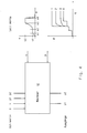
- the casting drive 1 shown in FIG. 1 is used to actuate a casting set 2, consisting of a casting chamber 3 with the molten metal 4 contained therein and a casting piston 5 for inserting the molten metal 4 into a mold cavity, not shown in any more detail.
- the casting piston 5 is connected to the casting drive 1 via a casting piston rod 6.
- the casting drive 1 consists of a front press cylinder 7, with a press piston 8 guided therein, which serves as a drive piston 8 for the associated piston rod 9.
- the piston rod 9 is connected to the casting piston rod 6.
- the press cylinder 7 has a front cylinder chamber 10 and a rear cylinder chamber 11, which are separated by the press piston 8.
- the front cylinder space 10 is connected to a pressure medium connection 14 via a radial and subsequently axial bore 12 in the cylinder head 13.
- the press cylinder 7 is followed by a multiplier device 15, consisting of a closed multiplier cylinder housing 16 with a multiplier piston 17 axially displaceable therein, which separates the multiplier cylinder chamber into a front closed cylinder chamber 18 and a rear closed cylinder chamber 19.
- the multiplier piston 17 points forward in a manner known per se, i. H. towards the casting set 2, pointing first piston rod 20, which extends through the cylinder wall of the multiplier cylinder housing into the rear cylinder space 11 of the press cylinder 7.
- the multiplier piston 17 also has a rear piston rod 21, which likewise extends laterally via the multiplier cylinder housing into a rear cylinder chamber 22 of an additional connection housing 23.
- the multiplier piston 17 with the front piston rod 20 and the rear piston rod 21 is penetrated by a central longitudinal bore 24, in which a check valve 25 is arranged.
- the check valve 25 is pressed away from the valve seat by means of a rod 26 projecting through the longitudinal bore 24 and thus opened.
- the rear cylinder space 19 of the multiplier cylinder can be acted upon by the pressure medium connection 28, the rear cylinder space 22 of the additional connection housing 23 via the pressure medium connection 29.
- Each position of the casting piston rod 6 or the piston rod 9 is detected by means of a displacement / speed / acceleration measuring device 30.
- the measuring device can be carried out, for example, as described in DE 32 09 834 A1.
- a series of quickly controllable servo-proportional valves also called continuous valves, is used to produce a real-time controlled two-circuit casting unit.
- continuous valve assemblies 33, 34 By using at least two continuous valve assemblies 33, 34 and by matching the corresponding piston surfaces A 1 of the plunger 8 and the annular surface A 2 of the multiplier piston 17 and the circular surfaces A 2.1 of the front piston rod 20 and A 2.2 of the rear piston rod 21 the motion sequence of the casting drive coordinates.
- Figure 2 the basic structure or the arrangement of the casting drive is shown again.
- the pressure in the pressure chambers 10, 11 or 18, 19 or 22 can be detected by means of p / U transducer and evaluated as a control signal.
- the servo-proportional valve 33 accordingly regulates the pressure conditions in the front cylinder chamber 10 (pressure p 2 at the transducer 44) of the press cylinder 7 and causes the press piston 8 to be clamped between the pressure chamber 10 (pressure p 2 ) and the pressure chamber 11 (pressure p 1 ).
- the latter can be detected by means of the p / U converter 45 and can therefore be regulated. The movement of the plunger 8 can thus be controlled.
- the servo-proportional valve 34 regulates the rear pressure chamber 19 of the multiplier piston 17, the front pressure chamber 18 of the multiplier piston preferably also being regulated via a further servo-proportional valve 35.
- These continuous valves can also be assigned p / U transducers, which are shown in more detail in FIG. 1, in order to detect and thus regulate the pressure conditions in the pressure chambers 18, 19.
- both the plunger 8 and the multiplier piston 17 are “clamped” on both sides, so that a sensitive movement can take place in all axial directions, ie forwards and backwards.
- the pressure in the individual pressure rooms continues to serve as the measured variable.
- the associated measurement data from the measurement devices 30, 31 or the p / U transducers 44, 45 etc. lead via measurement lines 39, 40 to a computer 41 (see FIGS.
- the continuous valve assemblies or servo proportional valves 33 to 36 are then controlled by the computer 41 so that the movement sequence of the casting drive can be checked and regulated in every phase during the casting process.
- the corresponding pressure P F in the mold cavity or the corresponding temperature sensors T F in the melt can be detected by corresponding additional pressure sensors in the mold cavity and fed to the computer 41 via the control lines 42, 43.
- Pressure peaks at the end of the mold filling phase can then be reduced or avoided altogether by braking the plunger 8 as well as by possibly reversing the multiplier piston 17 depending on these movements.
- the build-up of the holding pressure can also take place in an optimally short time by coordinating the movements of these two pistons, the regulation of the proportional valves 33 to 36 taking place in a time of less than 5 ms.
- the speed changes of the plunger 8 and thus the casting piston 5 to influence the casting speed can be influenced by tuning the amount of hydraulic medium flowing to the press cylinder 7 to act on the plunger 8 and to the multiplier cylinder to act on the multiplier piston 17, with higher accelerations of the two pistons being possible than this with the hydraulic medium supply from only one hydraulic medium reservoir. Appropriate clamping of the two pistons controls and influences any movement of the casting drive.
- the piston surfaces A 2.1 and A 2.2 are to be designed so that, for. B. during the forward movement of the multiplier piston, the amount of the medium flowing in at A 2.2 , ie the rear piston rod of the multiplier piston, for movement to the amount of the medium displaced at A 2.1 in the range of the ratio 0.8 to 1.2: 1.
- the diagrams shown in FIG. 4 relate to target value specifications for controlling the casting process.
- v f (s) as target value specification of the speed of the casting piston via the casting piston path.
- the values s 1 to s 4 represent certain waypoints of the casting piston, and a certain speed can be assigned to each waypoint. For example, in point s 4, the casting piston speed is braked to a residual speed shortly before the mold filling end.
Landscapes
- Engineering & Computer Science (AREA)
- Mechanical Engineering (AREA)
- Injection Moulding Of Plastics Or The Like (AREA)
Description
Die Erfindung betrifft ein Verfahren sowie eine Vorrichtung zur Durchführung des Verfahrens zur Prozeßsteuerung einer Druckgießmaschine nach dem Oberbegriff des Anspruchs 1 bzw. des Anspruchs 11,The invention relates to a method and a device for carrying out the method for process control of a die casting machine according to the preamble of
Aus der DE-PS 20 21 182 der Anmelderin ist eine Vorrichtung zum Einstellen der Preßkolbengeschwindigkeiten und -drücke bei Druckgießmaschinen bekannt geworden, welche nach dem sogenannten Drei-Phasen-System bei Kaltkammer-Druckgießmaschinen arbeitet. Diese Betriebsart wird zum Einstellen der beim Druckgießen erforderlichen unterschiedlichen Preßkolbengeschwindigkeiten und -drücke angewandt, wobei in der ersten und zweiten Arbeitsphase nur der auf den Gießkolben einwirkende Preßkolben des Preßzylinders über Druckmittelleitungen beaufschlagt wird und während der dritten Arbeitsphase eine Beaufschlagung eines als Stufenkolben ausgebildeten Multiplikatorkolbens erfolgt. Dabei wird bei dieser bekannten Einrichtung der Preßkolben in der ersten und zweiten Arbeitsphase über eine Bohrung mit Rückschlagventil im Multiplikatorkolben mit Druckmedium beaufschlagt. Aufgrund des wachsenden Drucks im Zylinderraum des Preßzylinders schließt sich die Bohrung im Multiplikatorkolben, so daß der Multiplikatorkolben während der dritten Phase (Nachdruckphase) mit seiner Kolbenflächenübersetzung auf den Preßkolben und damit auf den Gießkolben einwirkt.From DE-PS 20 21 182 of the applicant, a device for adjusting the ram speeds and pressures in die casting machines has become known, which operates according to the so-called three-phase system in cold chamber die casting machines. This operating mode is used to set the different plunger speeds and pressures required for die casting, with only the plunger of the press cylinder acting on the plunger being acted upon via pressure medium lines in the first and second working phases, and a multiplier piston designed as a stepped piston being acted upon during the third working phase. In this known device, the plunger is in the first and second working phase via a bore with a check valve in the multiplier piston with pressure medium acted upon. Due to the increasing pressure in the cylinder space of the press cylinder, the bore in the multiplier piston closes, so that during the third phase (holding pressure phase) the multiplier piston, with its piston surface ratio, acts on the press piston and thus on the casting piston.
Unter Drei-Phasen-System versteht man demnach den Ablauf des Gießverfahrens insbesondere bei waagrechter Kaltkammer-Druckgießmaschine mit einer Vorfüllphase der Gießkammer (erste Phase), einer Formfüllphase der Gießform (zweite Phase) und einer Nachdruckphase der Gießform (dritte Phase).The three-phase system is understood to mean the sequence of the casting process, particularly in the case of a horizontal cold chamber die casting machine, with a pre-filling phase of the casting chamber (first phase), a mold filling phase of the casting mold (second phase) and a holding pressure phase of the casting mold (third phase).
Die bekannte Einrichtung gemäß der DE-PS 20 21 182 wird darüber hinaus als Zweikreis-Gießaggregat bezeichnet, da im ersten Kreis während der ersten und zweiten Arbeitsphase der Preßkolben und im zweiten Kreis während der dritten Arbeitsphase der Multiplikatorkolben mit Druckmedium aus unterschiedlichen Kolbenspeichern beaufschlagt werden. Dabei wird bei der bekannten Einrichtung der Multiplikatorkolben mit einer beidseitig des Kolbens vorgesehenen Kolbenstange ausgeführt, so daß sich für die Druckbeaufschlagunng des Multiplikatorkolbens eine vordere Ringfläche am Multiplikatorkolben selbst und eine weitere Kreisfläche an der hinteren Kolbenstange ergibt. Dies hat den Vorteil, daß eine gesonderte Regelung des ringförmigen Druckraums am Multiplikatorkolben und des zusätzlichen hinteren Zylinderraums hinter der Kolbenstange ermöglicht wird. Zur Regelung dieser Druckräume sind Durchlaßventile vorgesehen, die durch Weggeber an der Kolbenstange des Preßkolbens oder an der hiermit verbundenen Kolbenstange des Gießkolbens angebracht sind. Dabei wird über die Ventilsteuerung zunächst der hintere Zylinderraum hinter der hinteren Kolbenstange des Multiplikatorkolbens mit Druckmedium beaufschlagt, welches über die Zentralbohrung zum Zylinderraum des Preßzylinders und damit zum Preßkolben gelangt (erste und zweite Arbeitsphase). Während der dritten Arbeitsphase (Nachdruckphase) wird durch einen Weggeber oder durch druckabhängiges Schalten ein weiteres Durchlaßventil zur Beaufschlagung des ringförmigen Zylinderraums des Multiplikatorkolbens und des hinteren Zylinderraums mit Druckmedium geöffnet, wobei die Mittelbohrung im Multiplikatorkolben sich bei Druckanstieg selbsttätig verschließt.The known device according to DE-PS 20 21 182 is also referred to as a two-circuit casting unit, since in the first circuit during the first and second working phases of the plunger and in the second circuit during the third working phase of the multiplier piston with pressure medium from different piston accumulators. In the known device, the multiplier piston is designed with a piston rod provided on both sides of the piston, so that there is a front annular surface on the multiplier piston itself and a further circular surface on the rear piston rod for pressurizing the multiplier piston. This has the advantage that a separate regulation of the annular pressure space on the multiplier piston and the additional rear cylinder space behind the piston rod is made possible. To regulate these pressure chambers, passage valves are provided, which are attached to the piston rod of the plunger or to the piston rod of the casting piston connected to it by displacement sensors. Via the valve control, pressure is first applied to the rear cylinder space behind the rear piston rod of the multiplier piston, which medium passes through the central bore to the cylinder space of the press cylinder and thus to the press piston (first and second Work phase). During the third working phase (holding pressure phase), a passage valve for pressurizing the annular cylinder chamber of the multiplier piston and the rear cylinder chamber with pressure medium is opened by a displacement sensor or by pressure-dependent switching, the center bore in the multiplier piston automatically closing when the pressure rises.
Bei dieser bekannten Vorrichtung wird das Druckmedium vor dem Preßkolben während der ersten und zweiten Arbeitsphase über eine Auslaßbohrung in einen Ölbehälter ohne besondere Regelung und Druckbeeinflussung herausgeschoben und bei der Rückstellung des Preßkolbens wieder eingelassen. Das Druckmedium vor dem Multiplikatorkolben im Zylinderraum des Multiplikators wird bei dessen Vorwärtsbewegung in der dritten Arbeitsphase (Nachdruckphase) ebenfalls über ein Drosselventil in einen Ölbehälter befördert und bei der Rückstellung des Multiplikatorkolbens entsprechend wieder eingepumpt. Die Regelung und Steuerung von Preßkolben und Multiplikatorkolben geschieht deshalb bei der bekannten Vorrichtung ausschließlich über den Zeitpunkt der Zuschaltung des Druckmediums zu den einzelnen Druckräumen im Preßzylinder sowie im Multiplikatorzylinder bzw. zum hinteren Zylinderraum, wobei zusätzliche Drosselventile eine gewisse Mengenregulierung durch einen Druckabfall ermöglichen. Eine sonstige Beeinflussung in der Steuerung ist aufgrund der fehlenden Regelmöglichkeiten nicht vorgesehen.In this known device, the pressure medium is pushed out in front of the plunger during the first and second working phases via an outlet bore into an oil container without special regulation and pressure control and is admitted again when the plunger is reset. The pressure medium in front of the multiplier piston in the cylinder chamber of the multiplier is also conveyed into an oil tank via a throttle valve when it moves forward in the third working phase (holding pressure phase) and is pumped in again when the multiplier piston is reset. The regulation and control of plunger and multiplier piston is therefore done in the known device only via the time the pressure medium is connected to the individual pressure chambers in the press cylinder and in the multiplier cylinder or to the rear cylinder chamber, additional throttle valves allowing a certain amount regulation by a pressure drop. There is no other influence in the control system due to the lack of control options.
Aus der Literaturstelle Ernst Brunnhuber: "Praxis der Druckgußfertigung", 3. Auflage, 1980, sind ebenfalls Multiplikatoranordnungen bekannt geworden, die auf den Seiten 70 bis 78 näher erläutert sind. Insbesondere sind auf den Seiten 73, 75 Multiplikatoranordnungen an einem Gießantrieb gezeigt, mittels welcher ebenfalls im Drei-Phasen-System gearbeitet werden kann. Dabei erfolgt die Zuschaltung des Druckspeichers für die Nachdruckphase ebenfalls über einen Impuls vom Gießkolben durch Öffnung eines Schußventils. In der Darstellung auf Seite 75 dieser Literaturstelle wird darüber hinaus eine zusätzliche Regelung des Multiplikatordruckes durch einen Gegendruck mittels eines weiteren Druckspeichers vorgeschlagen, mittels welchem die Vorwärtsbewegung des Multiplikatorkolbens abgebremst und damit Druckspitzen vermieden werden. Hierdurch kann in gewissem Umfang eine Regelung der Druckaufbauzeit in der dritten Arbeitsphase ermöglicht werden. Gemäß der Literaturangabe werden Druckanstiegszeiten durch die Druckspeicher von ca. 10 ms oder auch weniger erzielt. Ein entsprechendes Druck-Zeit-Diagramm ist auf der Seite 77 der Literaturstelle Brunnhuber zur Erläuterung angegeben.Multiplier arrangements have also become known from the literature reference Ernst Brunnhuber: "Praxis der Druckgußfertigung", 3rd edition, 1980, which are explained in more detail on pages 70 to 78. In particular, pages 73, 75 show multiplier arrangements on a casting drive, by means of which it is also possible to work in a three-phase system. The Activation of the pressure accumulator for the holding pressure phase also via an impulse from the casting piston by opening a shot valve. In the illustration on page 75 of this literature reference, additional regulation of the multiplier pressure by means of a counterpressure by means of a further pressure accumulator is proposed, by means of which the forward movement of the multiplier piston is braked and pressure peaks are thus avoided. To a certain extent, this allows regulation of the pressure build-up time in the third work phase. According to the literature, pressure rise times of about 10 ms or less are achieved by the pressure accumulator. A corresponding pressure-time diagram is given on page 77 of the Brunnhuber reference for explanation.
Bei einer Ausführungsform gemäß der Darstellung in der Literaturstelle Brunnhuber, Seite 78, wird auf eine Durchgangsbohrung im Multiplikatorkolben verzichtet und die Druckbeaufschlagung des Preßkolbens unmittelbar im dahinterliegenden Zylinderraum vorgenommen. In diesem Fall wirkt ein erster Druckspeicher unmittelbar auf den Zylinderraum des Preßkolbens, auch Antriebskolben genannt. Ein zweiter Druckspeicher wirkt durch den entsprechenden Impuls auf den Multiplikatorkolben.In one embodiment, as shown in the Brunnhuber literature, page 78, there is no through hole in the multiplier piston and the pressurization of the plunger is carried out directly in the cylinder space behind it. In this case, a first pressure accumulator acts directly on the cylinder space of the plunger, also called the drive piston. A second pressure accumulator acts on the multiplier piston through the corresponding pulse.
Neben den genannten Literaturstellen sind eine Vielzahl von Literaturstellen bekannt geworden, die sich mit der Prozeßsteuerung sowohl beim Spritzgießen als auch beim Druckgießen beschäftigen. Insbesondere aus der Literaturstelle Klein: "Automatische Gießprozeßüberwachung beim Druckgießen", Gießerei 68, (1981), Nr. 18, Seite 531 ff., ist eine solche Gießprozeßüberwachung bekannt geworden, bei welcher eine Vielzahl von Parametern, wie Formfüllzeit, Druckaufbauzeit, Druck der Schmelze, Formfüllungsgrad, Temperatur der Schmelze usw., als Ist-Werte erfaßt und mit vorgegebenen Soll-Werten verglichen werden.In addition to the cited references, a large number of references have become known which deal with process control both in injection molding and in die casting. Such a casting process monitoring has become known in particular from the literature reference Klein: "Automatic casting process monitoring during die casting", Gießerei 68, (1981), No. 18, page 531 ff., In which a large number of parameters, such as mold filling time, pressure build-up time, pressure of the Melt, degree of mold filling, temperature of the melt, etc., recorded as actual values and compared with predetermined target values.
Bei einer schlechten Qualität des Erzeugnisses werden die Ist-Werte und ggf. auch die Soll-Werte korrigiert, um in nächstfolgenden Gießvorgängen eine Verbesserung des Gießergebnisses zu erzielen. Die Gießbedingungen werden demnach während des Druckgießprozesses überwacht und in nachfolgenden Gießprozessen ggf. korrigiert.If the quality of the product is poor, the actual values and possibly also the target values are corrected in order to improve the casting result in subsequent casting processes. The casting conditions are therefore monitored during the die casting process and corrected if necessary in subsequent casting processes.
Alle bekannten Gießprozeßüberwachungsmethoden haben den Nachteil, daß die während des Gießprozesses ermittelten Gießparameter nicht unmittelbar auf den gerade stattfindenden Gießprozeß einwirken können, da eine Rückkopplung von ermittelten Gießparametern nicht vorgesehen ist.All known casting process monitoring methods have the disadvantage that the casting parameters determined during the casting process cannot act directly on the casting process that is currently taking place, since a feedback of the determined casting parameters is not provided.
Der Erfindung liegt die Aufgabe zugrunde, ein verbessertes Verfahren zur Gießprozeßüberwachung und insbesondere zur Prozeßregelung einer Druckgießmaschine sowie eine entsprechende Vorrichtung zur Durchführung des Verfahrens vorzuschlagen.The invention is based on the object of proposing an improved method for monitoring the casting process and in particular for regulating the process of a die casting machine and a corresponding device for carrying out the method.
Diese Aufgabe wird ausgehend vom Gattungsbegriff des jeweiligen Verfahrens- bzw. Vorrichtungs-Hauptanspruchs durch die kennzeichnenden Merkmale der jeweiligen Schutzrechtsansprüche gelöst.This task is solved on the basis of the generic concept of the respective process or device main claim by the characterizing features of the respective property right claims.
In den Unteransprüchen sind vorteilhafte und zweckmäßige Weiterbildungen der Erfindung angegeben.Advantageous and expedient developments of the invention are specified in the subclaims.
Das erfindungsgemäße Verfahren bzw. die entsprechende Vorrichtung zur Durchführung des Verfahrens hat gegenüber dem bekannten Stand der Technik den Vorteil, daß ein sogenanntes echtzeit-geregeltes Zweikreis-Gießaggregat geschaffen wird, mit welchem eine unmittelbare Beeinflussung der Gießparameter während des Gießprozesses ermöglicht wird. Dies geschieht insbesondere dadurch, daß die Bewegung des Preßkolbens bzw. Antriebskolbens für den Gießkolben in jeder Phase seiner Bewegung kontrolliert und geregelt ablaufen kann. Das gleiche gilt für die Bewegung des Multiplikatorkolbens während dessen Bewegung in der dritten Arbeitsphase. Der Preßkolben oder Antriebskolben wird im zugehörigen Preßzylinder und der Multiplikatorkolben im zugehörigen Multiplikatorzylinderraum quasi zwischen einem vorderen und einem hinteren regelbaren Druckpolster quasi "eingespannt", so daß während der Drei-Phasen-Bewegung die jeweiligen Kolben in ihrer Vorwärtsbewegung oder auch Rückwärtsbewegung sowohl in ihrer Geschwindigkeit als auch in ihrem Beschleunigungsverhalten separat und aufeinander abgestimmt geregelt werden können. Der Zylinderraum vor dem Preßkolben und vor dem Multiplikatorkolben wird demnach als regelbarer Druckraum verwendet, wobei die diesbezüglich bekannte Regelung bei Multiplikatorkolben dahingehend verbessert wird, daß eine unmittelbare Rückkopplung der Regelwerte erfolgen kann.The method according to the invention or the corresponding device for carrying out the method has the advantage over the known prior art that a so-called real-time controlled two-circuit casting unit is created, with which a direct influence on the casting parameters is made possible during the casting process. This happens in particular in that the movement of the plunger or drive piston for the casting piston can be controlled and regulated in every phase of its movement. The same applies to the movement of the multiplier piston during its movement in the third working phase. The plunger or drive piston is quasi "clamped" in the associated press cylinder and the multiplier piston in the associated multiplier cylinder space between a front and a rear adjustable pressure cushion, so that during the three-phase movement the respective pistons move forward or backward in both their speed as well as their acceleration behavior can be regulated separately and in a coordinated manner. The cylinder space in front of the plunger and in front of the multiplier piston is accordingly used as a controllable pressure chamber, the regulation known in this regard being improved in the case of multiplier pistons in such a way that the control values can be fed back directly.
Diese Regelung ist durch den Einsatz von äußerst schnell reagierenden sogenannten Servo-Proportional-Regelventilen in den jeweiligen Steuerkreisen möglich, die auch als sogenannte "Stetig-Ventile" bezeichnet werden.This regulation is possible through the use of extremely fast reacting so-called servo-proportional control valves in the respective control circuits, which are also referred to as so-called "continuous valves".
Durch diese Regelungsmöglichkeit können Druckspitzen am Ende der Formfüllphase sowohl durch Abbremsen des Preßkolbens als auch durch eventuelles Rückwärtssteuern des Multiplikatorkolbens in gegenseitiger Abhängigkeit dieser Bewegungen abgebaut bzw. verhindert werden. Auch die dritte Arbeitsphase mit dem Nachdruckaufbau kann durch eine Abstimmung der Bewegung der beiden Kolben in optimal kurzer Zeit erfolgen, wobei die Regelzeiten unter 5 ms erfolgt.With this control option, pressure peaks at the end of the mold filling phase can be reduced or prevented both by braking the plunger and by possibly reversing the multiplier piston depending on these movements. The third working phase with the build-up of holding pressure can also be carried out in an optimally short time by coordinating the movement of the two pistons, the control times taking less than 5 ms.
Jegliche Geschwindigkeitsänderung des Gießkolbens kann demnach durch eine Steuerung und Regelung des Preßkolbens allein in der ersten und zweiten Arbeitsphase und des Multiplikatorkolbens in der dritten Arbeitsphase durch Abstimmung der zu diesen beiden Zylinderräumen zufließenden Hydraulikmenge erfolgen, wobei höhere Beschleunigungen möglich sind, als dies mit einer Hydraulikmediumversorgung aus nur einem Hydraulikmediumreservoir möglich ist.Any change in the speed of the casting plunger can therefore be achieved by controlling the plunger in the first and second working phases alone and the multiplier plunger in the third working phase by coordinating the hydraulic quantity flowing to these two cylinder spaces, with higher accelerations are possible than is possible with a hydraulic medium supply from only one hydraulic medium reservoir.
Weitere Einzelheiten und Vorteile der Erfindung sind in der nachfolgenden Beschreibung eines Ausführungsbeispiels der Erfindung angegeben. Im einzelnen zeigt
Figur 1- eine schematische Darstellung einer Vorrichtung zur Durchführung des Verfahrens zur erfindungsgemäßen Prozeßsteuerung,
Figur 2- weitere Einzelheiten aus
Figur 1, Figur 3- eine weitere Ausführungsvariante und
Figur 4- einen zentralen Rechner mit Regelfunktion für die zu verarbeitenden Daten.
- Figure 1
- 1 shows a schematic representation of a device for carrying out the method for process control according to the invention,
- Figure 2
- further details from FIG. 1,
- Figure 3
- a further embodiment variant and
- Figure 4
- a central computer with control function for the data to be processed.
Der in der Figur 1 dargestellte Gießantrieb 1 dient zur Betätigung einer Gießgarnitur 2, bestehend aus einer Gießkammer 3 mit darin enthaltener Metallschmelze 4 und einem Gießkolben 5 zum Einschub der Metallschmelze 4 in einen nicht näher dargestellten Formhohlraum. Der Gießkolben 5 ist über eine Gießkolbenstange 6 mit dem Gießantrieb 1 verbunden. Der Gießantrieb 1 besteht aus einem vorderen Preßzylinder 7, mit einem darin geführten Preßkolben 8, der als Antriebskolben 8 für die zugehörige Kolbenstange 9 dient. Die Kolbenstange 9 ist mit der Gießkolbenstange 6 verbunden. Der Preßzylinder 7 weist einen vorderen Zylinderraum 10 und einen hinteren Zylinderraum 11 auf, die durch den Preßkolben 8 getrennt sind. Der vordere Zylinderraum 10 wird über eine radiale und nachfolgend axiale Bohrung 12 im Zylinderkopf 13 mit einem Druckmediumanschluß 14 verbunden.The
Dem Preßzylinder 7 schließt sich eine Multiplikatoreinrichtung 15 an, bestehend aus einem geschlossenen Multiplikatorzylindergehäuse 16 mit einem darin axial verschiebbaren Multiplikatorkolben 17, der den Multiplikatorzylinderraum in einen vorderen geschlossenen Zylinderraum 18 und einen hinteren geschlossenen Zylinderraum 19 auftrennt. Dabei weist der Multiplikatorkolben 17 in an sich bekannter Weise eine nach vorne hin, d. h. zur Gießgarnitur 2 hin, weisende erste Kolbenstange 20 auf, die sich durch die Zylinderwandung des Multiplikatorzylindergehäuses in den hinteren Zylinderraum 11 des Preßzylinders 7 hinein erstreckt. Der Multiplikatorkolben 17 weist darüber hinaus eine hintere Kolbenstange 21 auf, die sich ebenfalls über das Multiplikatorzylindergehäuse seitlich in einen hinteren Zylinderraum 22 eines zusätzlichen Anschlußgehäuses 23 erstreckt. Der Multiplikatorkolben 17 mit vorderer Kolbenstange 20 und hinterer Kolbenstange 21 wird durch eine zentrale Längsbohrung 24 durchsetzt, in welchem ein Rückschlagventil 25 angeordnet ist. In der hintersten Stellung des Multiplikatorkolbens 17 wird das Rückschlagventil 25 mittels einer durch die Längsbohrung 24 hindurchragenden Stange 26 vom Ventilsitz weggedrückt und damit geöffnet.The
Der hintere Zylinderraum 19 des Multiplikatorzylinders ist über den Druckmediumanschluß 28, der hintere Zylinderraum 22 des zusätzlichen Anschlußgehäuses 23 über den Druckmediumanschluß 29 mit Druckmedium beaufschlagbar.The
Jede Position der Gießkolbenstange 6 bzw. der Kolbenstange 9 wird mittels einer Weg/Geschwindigkeits/Beschleunigungs-Meßeinrichtung 30 erfaßt. Gleiches gilt für die Meßeinrichtung 31 zur Erfassung jeglicher Position sowie des Weges, der Geschwindigkeit, der Beschleunigung des Multiplikatorkolbens 17. Hierfür ragt eine verschiebbare Meßstange 32 vom Multiplikatorkolben 17 parallel zur Längsachse zur entsprechenden Meßeinrichtung 30. Die Meßeinrichtung kann beispielsweise ausgeführt werden, wie es in der DE 32 09 834 A1 beschrieben ist.Each position of the
Der prinzipielle Aufbau des Gießantriebs für die Gießgarnitur ist auch in der eingangs erwähnten Patentschrift PS 20 21 182 der Anmelderin beschrieben. Auf den gesamten Inhalt dieser Patentschrift wird, soweit er für die vorliegenden Erfindung maßgeblich ist, hiermit ausdrücklich Bezug genommen.The basic structure of the casting drive for the casting set is also described in the aforementioned
Erfindungsgemäß wird zur Herstellung eines echtzeitgeregelten Zweikreis-Gießaggregats eine Reihe von schnell regelbaren Servo-Proportional-Ventilen, auch Stetig-Ventile genannt, verwendet. Durch den Einsatz von wenigstens zwei Stetig-Ventil-Baugruppen 33, 34 sowie durch Abstimmung der entsprechenden Kolbenflächen A1 des Preßkolbens 8 und der Kreisringfläche A2 des Multiplikatorkolbens 17 sowie der Kreisflächen A2.1 der vorderen Kolbenstange 20 und A2.2 der hinteren Kolbenstange 21 wird der Bewegungsablauf des Gießantriebs koordiniert. In Figur 2 ist der prinzipielle Aufbau bzw. die Anordnung des Gießantriebs nochmals dargestellt.According to the invention, a series of quickly controllable servo-proportional valves, also called continuous valves, is used to produce a real-time controlled two-circuit casting unit. By using at least two
Mittels p/U-Meßwertumformer kann der Druck in den Druckräumen 10, 11 bzw. 18, 19 bzw. 22 erfaßt und als Regelsignal ausgewertet werden.The pressure in the
Das Servo-Proportional-Ventil 33 regelt demnach die Druckverhältnisse im vorderen Zylinderraum 10 (Druck p2 am Meßwertumformer 44) des Preßzylinders 7 und bewirkt eine Art Einspannung des Preßkolbens 8 zwischen dem Druckraum 10 (Druck p2) und dem Druckraum 11 (Druck p1). Letzteres ist mittels des p/U-Umformers 45 erfaßbar und dadurch regelbar. Die Bewegung des Preßkolbens 8 kann damit kontrolliert erfolgen.The servo-
Gleichermaßen erfolgt durch das Servo-Proportional-Ventil 34 eine Regelung des hinteren Druckraums 19 des Multiplikatorkolbens 17, wobei vorzugsweise der vordere Druckraum 18 des Multiplikatorkolbens ebenfalls über ein weiteres Servo-Proportional-Ventil 35 geregelt wird. Auch diesen Stetigventilen können in Fig. 1 näher dargestellte p/U-Meßwertumformer zugeordnet sein, um die Druckverhältnisse in den Druckräumen 18, 19 zu erfassen und damit zu regeln.Similarly, the servo-
Schließlich wird zur Regelung des hinteren Zylinderraums 22 ebenfalls die Regelung eines schnell schaltenden Servo-Proportional-Ventils 36 am Druckmediumanschluß 29 herangezogen, so daß die Beaufschlagung des Druckraumes 22 über einen ersten Druckspeicher 37 und die Beaufschlagung des Druckraumes 19 über einen zweiten Druckspeicher 38 über eine schnell schaltende Proportional-Ventilsteuerung erfolgen kann. Auch hier können zusätzliche p/U-Meßwertumformer eingesetzt werden.Finally, for the regulation of the
Durch diese Maßnahmen wird sowohl der Preßkolben 8 als auch der Multiplikatorkolben 17 beidseitig "eingespannt", so daß eine feinfühlige Bewegung in allen axialen Richtungen, d. h. vorwärts und rückwärts, erfolgen kann. Die Steuerung bzw. Regelung des Gießantriebs erfolgt durch die laufende Bestimmung der Lage "s", der Geschwindigkeit "v" oder der Beschleunigung sowohl der Gießkolbenstange 6 als auch des Multiplikatorkolbens 17 während des Gießprozesses, wie dies auch in den beiden Diagrammen ![]()
![]()
![]()
![]()
Die Geschwindigkeitsänderungen des Preßkolbens 8 und damit des Gießkolbens 5 zur Beeinflussung der Gießgeschwindigkeit kann durch Abstimmung der zum Preßzylinder 7 zur Beaufschlagung des Preßkolbens 8 und zum Multiplikatorzylinder zur Beaufschlagung des Multiplikatorkolbens 17 zufließenden Hydraulikmediummenge beeinflußt werden, wobei höhere Beschleunigungen der beiden Kolben möglich sind, als dies mit der Hydraulikmediumversorgung aus nur einem Hydraulikmediumreservoir möglich ist. Durch die entsprechende Einspannung der beiden Kolben wird dabei jegliche Bewegung des Gießantriebs kontrolliert und beeinflußt.The speed changes of the
Vor allem die Kolbenflächen A2.1 und A2.2 sind so auszulegen, daß, z. B. bei der Vorwärtsbewegung des Multiplikatorkolbens, die Menge des bei A2.2, d. h. der hinteren Kolbenstange des Multiplikatorkolbens, zur Bewegung zufließenden Mediums zur Menge des bei A2.1 verdrängten Mediums im Bereich des Verhältnisses 0,8 bis 1,2 : 1 liegen. Dabei verhält sich die Kreiszylinderfläche A1 des Preßkolbens 8 zur Summe der Flächen aus A2 + A2.2 im Verhältnis von 1 : 2,5 bis 4. Diese Abstimmung der Flächen ermöglicht einen optimalen Betrieb des Gießantriebs.In particular, the piston surfaces A 2.1 and A 2.2 are to be designed so that, for. B. during the forward movement of the multiplier piston, the amount of the medium flowing in at A 2.2 , ie the rear piston rod of the multiplier piston, for movement to the amount of the medium displaced at A 2.1 in the range of the ratio 0.8 to 1.2: 1. The behaves Circular cylinder area A 1 of the
In einem vereinfachten, alternativen Ausführungsbeispiel nach Fig. 3 wird lediglich der vordere Druckraum 10 des Preßzylinders 7 sowie der hintere Druckraum 19 der Multiplikatoreinrichtung 15 über die dargestellten Stetigventile 33, 34 geregelt. Dabei erfolgt wiederum die Meßwerterfassung zur "Einspannung" des Antriebskolbens 8 über die beiden p/U-Meßwertumformer 44, 45 mit den erfaßten Ist-Wert-Signalen p1, p2, die zu Stellwertsignalen y1, y2 am Ausgang des Rechners 41 führen. Die entsprechenden Regelfunktionen sind in Fig. 4 wiedergegeben.In a simplified, alternative exemplary embodiment according to FIG. 3, only the
Die in Fig. 4 dargestellten Diagramme betreffen Soll-Wert-Vorgaben zur Regelung des Gießprozesses.The diagrams shown in FIG. 4 relate to target value specifications for controlling the casting process.
Die in dem Diagramm ![]()
![]()
![]()
![]()
Gleiches gilt für das Diagramm ![]()
![]()
Claims (14)
- Method for controlling the process of a die casting machine, with a casting chamber (3) for the molten metal (4) and a casting piston (5), with a pressing cylinder (7) following the casting chamber (3), with a pressing piston (8) for driving the casting piston (5) and with a multiplier device (15) following the pressing cylinder (7), with a multiplier piston (17) guided therein, the casting drive (1) being constructed as a two-circuit casting unit and a pressure medium acting by means of a first valve control mechanism (36) directly on the pressing piston (8) and by means of a further valve control mechanism (34) on the multiplier piston (17), characterised in that the two-circuit casting drive is controlled by means of quickly adjustable servo-proportional valves (33 to 36) (continuous valves), the control taking place by means of at least one servo-proportional valve (33, 34) located in the inlet or outlet (14) to the pressure chamber (10) in front of the pressing piston (8) as well as in the inlet or outlet (28) of the pressure chamber (19) behind the multiplier piston (17), that the entire movements of the pressing piston (8) and thus of the casting piston (5) as well as the movements of the multiplier piston (17) are ascertained by way of distance/speed measuring devices (30, 31) as well as the pressures in the pressure chambers of the pressing cylinder (7) and/or multiplier device (15), that the control or regulation of the servo-proportional valves (33, 34) takes place depending on each other and depending on the movements of the pressing piston (8) or of the multiplier piston (17) as well as on the pressures and possibly further casting parameters in the moulding cavity by means of a computer (41), so that the current injection process during the pre-filling phase and/or the mould-filling phase and/or the subsequent pressure phase takes place by a controlled movement of the pressing piston (8) in conjunction with the movement of the multiplier piston (17) at the required reference values.
- Method according to Claim 1, characterised in that the multiplier device (15) comprises a multiplier piston (17) with an effective rear pressing surface A2 in the shape of a circular ring, in a closed multiplier cylinder housing (16), in which case a first front piston rod (20) of the multiplier piston (17) with an effective front pressure surface A2.1 opens into the pressure chamber (11) of the pressing cylinder (7) and a second, rear piston rod (21) of the multiplier piston (17) with an effective pressure surface A2.2 opens into a further, rear pressure chamber (22) and the multiplier piston (17) with its two piston rods (20, 21) comprising a common longitudinal axis, having a longitudinal bore (24) with a non-return valve (25).
- Method according to Claim 1 or 2, characterised in that provided in the inlet or outlet of the pressure chamber (18) located in front of the multiplier piston (17) is a further rapidly adjustable servo-proportional valve (35) and/or provided in the inlet or outlet of the rear pressure chamber (22) for the rear piston rod (21) is a further rapidly adjustable servo-proportional valve (36).
- Method according to one of Claims 1 to 3, characterised in that by means of the servo-proportional valve control arrangement on the pressing cylinder (7) and on the multiplier device (15), at the end of the mould-filling phase, a deceleration of the pressing piston (8) by a counter pressure actuation of the pressing piston (8) takes place in the pressure chamber (10), in order to minimize pressure peaks in the casting mould.
- Method according to one of Claims 1 to 4, characterised in that by means of the servo-proportional valve control arrangement on the multiplier device (15), a deceleration or a reverse control of the multiplier piston (17) takes place, in order to minimize pressure peaks in the casting mould.
- Method according to one or more of the preceding Claims, characterised in that by means of the servo-proportional valve control arrangement, the movement of the pressing piston (8) with respect to the movement of the multiplier piston is coordinated within optimum short times of t≤ 0.5 ms with each other so that optimum subsequent pressure values can be achieved in the third working phase.
- Method according to one or more of the preceding Claims, characterised in that the pressing piston (8) and/or the multiplier piston (17) is "clamped" during its movement constantly between two pressure cushions, in which case preferably the bilateral pressure cushions of the pressure chambers (10, 11) or (18, 19) and thus the movements of the pistons (8, 17) being adjustable by means of a servo-proportional valve control arrangement of the valves (33 to 36) within a regulating time of preferably t≤ 5 ms.
- Method according to one or more of the preceding Claims, characterised in that the pressing piston (8) and/or the multiplier piston (17) is variable in its speed within a time interval of t≤ 5 ms.
- Method according to Claim 2, characterised in that the ratio of the piston surface A2.1 of the front piston rod (20) to the piston surface A2.2 of the rear piston rod (21) is measured such that at the time of the forwards movement of the multiplier piston (17), the quantity m1 of the pressure medium flowing towards the rear piston rod (21) with respect to the quantity m2 of the pressure medium compressed in the pressure chamber (11) at the front piston rod (20) has a ratio of m1:m2 = 0.8 to 1.2:1.
- Method according to one or more of the preceding Claims, characterised in that the effective pressure surface A1 of the pressing piston (8) in the pressure chamber (11) with respect to the surface difference of the multiplier circular ring surface A2 in the annular chamber (19) plus the effective pressure surface A2.2 of the rear piston rod (21) in the pressure chamber (22) has a ratio of A1:(A2 + A2.2) = 1:(2.5 to 4).
- Apparatus for carrying out the method according to one or more of the preceding Claims, with a casting lining (2), a subsequent casting drive (1), consisting of a pressing cylinder (7) with pressing piston (8) and a multiplier device (15) with multiplier piston (17), the casting drive being constructed as a two-circuit casting unit, characterised in that a valve control arrangement for the two-circuit casting drive is provided, which consists of rapidly adjustable servo-proportional valves (33 to 36) with an adjusting time t≤ 5 ms, in which case at least the inlet or outlet of the pressing cylinder (7) as well as the inlet or outlet of the multiplier device (15) is provided with rapidly adjustable servo-proportional valves (33, 34) and in which case the entire movements of the casting piston rod (6) and of the multiplier piston (17) can be monitored by way of distance/speed measuring devices (30, 31), and a computer being provided for controlling or regulating the servo-proportional valves depending on the movements of the casting piston rod (6) and of the multiplier piston (17).
- Apparatus according to Claim 11, characterised in that the multiplier device (15) is provided with a multiplier piston (17) and a front piston rod (20) connected thereto and a rear piston rod (21) as well as a central longitudinal bore (24) with a non-return valve (25), the front pressure chamber (18) and the rear pressure chamber (19) being adjustable by means of servo-proportional valves (34, 35) for clamping the multiplier piston (17).
- Apparatus according to Claim 10 or 11, characterised in that the pressure chamber (22) lying behind the rear piston rod (21) of the multiplier piston can be regulated by means of a servo-proportional valve control arrangement (36) as a pressure chamber.
- Apparatus according to Claim 10 or 11, characterised in that the pressure in the pressure chambers (10, 11) or (18, 19) for "clamping" the pressing piston (8) or the multiplier piston (17) can be monitored by means of signal modulators (44, 45 etc.) and can be supplied as an actual value to the computer (41).
Applications Claiming Priority (2)
| Application Number | Priority Date | Filing Date | Title |
|---|---|---|---|
| DE4218556A DE4218556A1 (en) | 1992-06-05 | 1992-06-05 | Method and device for carrying out the method for process control of a die casting machine |
| DE4218556 | 1992-06-05 |
Publications (3)
| Publication Number | Publication Date |
|---|---|
| EP0576795A1 EP0576795A1 (en) | 1994-01-05 |
| EP0576795B1 true EP0576795B1 (en) | 1997-05-28 |
| EP0576795B2 EP0576795B2 (en) | 2002-01-16 |
Family
ID=6460458
Family Applications (1)
| Application Number | Title | Priority Date | Filing Date |
|---|---|---|---|
| EP93106696A Expired - Lifetime EP0576795B2 (en) | 1992-06-05 | 1993-04-24 | Method and apparatus to controle the process of a die casting machine |
Country Status (5)
| Country | Link |
|---|---|
| US (1) | US5365999A (en) |
| EP (1) | EP0576795B2 (en) |
| JP (1) | JPH0631427A (en) |
| DE (2) | DE4218556A1 (en) |
| ES (1) | ES2102547T5 (en) |
Families Citing this family (18)
| Publication number | Priority date | Publication date | Assignee | Title |
|---|---|---|---|---|
| DE4419848C1 (en) * | 1994-06-07 | 1995-12-21 | Frech Oskar Gmbh & Co | Hot chamber die casting machine |
| US5630463A (en) * | 1994-12-08 | 1997-05-20 | Nelson Metal Products Corporation | Variable volume die casting shot sleeve |
| DE19529279C1 (en) * | 1995-08-09 | 1996-11-21 | Bayerische Motoren Werke Ag | Pressure die-casting machine |
| US5988260A (en) * | 1996-03-05 | 1999-11-23 | Toshiba Kikai Kabushiki Kaisha | Method for controlling injection in a die casting machine and apparatus for the same |
| US6082438A (en) * | 1997-10-08 | 2000-07-04 | Outboard Marine Corporation | Method and system for the control of a vacuum valve of a vacuum die casting machine |
| BE1010155A6 (en) * | 1997-11-05 | 1998-01-06 | Buehler Ag | Method for operating a drive piston and device for the implementation thereof. |
| JP3530730B2 (en) * | 1997-11-27 | 2004-05-24 | 東芝機械株式会社 | Injection control method and apparatus for die casting machine |
| JP3332871B2 (en) * | 1998-11-02 | 2002-10-07 | 東芝機械株式会社 | Injection control method and apparatus for die casting machine |
| EP1274526B1 (en) * | 2000-04-20 | 2004-03-03 | ProControl AG | Method and drive system for the control/regulation of linear pressure/cast movement |
| JP3878540B2 (en) * | 2002-11-22 | 2007-02-07 | 東洋機械金属株式会社 | Die casting machine |
| WO2008086181A1 (en) * | 2007-01-05 | 2008-07-17 | Buhlerprince, Inc. | Die casting machine with reduced static injection pressure |
| KR100801749B1 (en) * | 2007-10-16 | 2008-02-11 | 주식회사 한반도건축감리건축사사무소 | A tree protector of apartment house |
| DE102008055536A1 (en) * | 2008-12-17 | 2010-07-01 | Bühler Druckguss AG | Method for operating a drive piston of a die casting machine and device for carrying out the method |
| PL2295171T3 (en) * | 2009-09-15 | 2013-04-30 | Richard Oberle | Method and hydraulic switching assembly for operating a metal pressure casting assembly |
| EP3421155B1 (en) * | 2017-06-28 | 2019-06-19 | Parker Hannifin Manufacturing Germany GmbH & Co. KG | Hydraulic circuit device for a cold chamber casting machine |
| DE102020100588B4 (en) * | 2020-01-13 | 2021-10-07 | AHP Merkle GmbH | Measuring device for a redensification arrangement as well as a method for process control of redensification in a casting process |
| DE102020204634A1 (en) | 2020-04-09 | 2021-10-14 | Oskar Frech Gmbh + Co. Kg | Casting piston system and casting process for a die casting machine |
| DE102020004742A1 (en) | 2020-08-05 | 2022-02-10 | Daimler Ag | Drive device for a die-casting system for the production of die-cast components |
Family Cites Families (20)
| Publication number | Priority date | Publication date | Assignee | Title |
|---|---|---|---|---|
| DE2021182C3 (en) * | 1970-04-30 | 1978-03-30 | Maschinenfabrik Weingarten Ag, 7987 Weingarten | Device for setting the plunger speeds and pressures in die-casting machines with a three-phase system, especially in cold-chamber die-casting machines |
| JPS518097B1 (en) * | 1970-12-29 | 1976-03-13 | ||
| US4011902A (en) * | 1973-10-08 | 1977-03-15 | Gebrueder Buehler Ag | Device for pressure casting |
| SU562380A1 (en) * | 1975-12-08 | 1977-06-25 | Специальное Конструкторское Бюро По Проектированию Машин Для Точного Литья При Заводе "Литмаш" Им.С.М.Кирова | Machine injection molding machine |
| JPS5819383B2 (en) * | 1977-02-15 | 1983-04-18 | 東芝機械株式会社 | injection molding equipment |
| DE2801829C3 (en) * | 1978-01-17 | 1985-02-21 | Maschinenfabrik Müller-Weingarten AG, 7987 Weingarten | Method and device for controlling a die casting machine |
| DE2922914A1 (en) * | 1979-06-06 | 1980-12-11 | Oskar Frech Werkzeugbau Gmbh & | METHOD AND ARRANGEMENT FOR CONTROLLING THE INPRESSION PROCESS IN COLD CHAMBER DIE CASTING MACHINES |
| SU900965A1 (en) * | 1980-06-10 | 1982-01-30 | Научно-Исследовательский Институт Специальных Способов Литья | Moulding unit of pressure die casting machine |
| JPS57128526A (en) * | 1981-02-04 | 1982-08-10 | Toshiba Mach Co Ltd | Pressure controller for injection molding machine |
| JPS5914305B2 (en) * | 1981-03-18 | 1984-04-04 | 東芝機械株式会社 | Ram displacement detection device in die-casting machine |
| JPS57187154A (en) * | 1981-05-15 | 1982-11-17 | Toyota Motor Corp | Method and device for inspecting quality of product produced by die casting machine |
| DE3142811A1 (en) † | 1981-10-28 | 1983-05-05 | Idra Pressen GmbH, 7000 Stuttgart | Method and apparatus for controlling the movement of a casting piston during the injection process on a die-casting machine |
| JPS58212850A (en) * | 1982-06-03 | 1983-12-10 | Toshiba Mach Co Ltd | Method for regulating injection condition automatically |
| US4858103A (en) * | 1983-02-07 | 1989-08-15 | Tokyo Keiki Company, Ltd. | Fluid valve control system for controlling fluid pressure or flow |
| JPS59218505A (en) * | 1983-05-26 | 1984-12-08 | Toshiba Mach Co Ltd | Hydraulic controller using closed loop |
| DE3329705A1 (en) * | 1983-08-17 | 1985-03-07 | Ortwin Prof.Dr.-Ing. Hahn | Diecasting machine with control apparatus for pressure-dependent control of the casting process |
| JPS61150764A (en) * | 1984-12-24 | 1986-07-09 | Nippon Denso Co Ltd | Diecasting method |
| JPH02142664A (en) * | 1988-11-21 | 1990-05-31 | Toshiba Mach Co Ltd | Hydraulic driving circuit in injection cylinder for die casting machine |
| US5052909A (en) * | 1990-01-19 | 1991-10-01 | Cincinnati Milacron Inc. | Energy-conserving injection molding machine |
| US5207267A (en) * | 1990-08-09 | 1993-05-04 | Toshiba Kikai Kabushiki Kaisha | Injection control method of die cast machine |
-
1992
- 1992-06-05 DE DE4218556A patent/DE4218556A1/en not_active Withdrawn
-
1993
- 1993-04-24 DE DE59306564T patent/DE59306564D1/en not_active Expired - Lifetime
- 1993-04-24 EP EP93106696A patent/EP0576795B2/en not_active Expired - Lifetime
- 1993-04-24 ES ES93106696T patent/ES2102547T5/en not_active Expired - Lifetime
- 1993-05-10 US US08/058,254 patent/US5365999A/en not_active Expired - Lifetime
- 1993-05-17 JP JP5114922A patent/JPH0631427A/en active Pending
Also Published As
| Publication number | Publication date |
|---|---|
| JPH0631427A (en) | 1994-02-08 |
| DE4218556A1 (en) | 1993-12-09 |
| ES2102547T5 (en) | 2002-08-16 |
| DE59306564D1 (en) | 1997-07-03 |
| US5365999A (en) | 1994-11-22 |
| EP0576795B2 (en) | 2002-01-16 |
| ES2102547T3 (en) | 1997-08-01 |
| EP0576795A1 (en) | 1994-01-05 |
Similar Documents
| Publication | Publication Date | Title |
|---|---|---|
| EP0576795B1 (en) | Method and apparatus to controle the process of a die casting machine | |
| DE2645849A1 (en) | HYDRAULICALLY DRIVEN PRESS | |
| DE3021978C2 (en) | ||
| DE102004023150A1 (en) | Injection system and casting process of a casting machine | |
| DE102008055536A1 (en) | Method for operating a drive piston of a die casting machine and device for carrying out the method | |
| DE4203401A1 (en) | METHOD AND DEVICE FOR CONTROLLING A POWDER MOLD PRESS | |
| DE10248797A1 (en) | High speed drive method and device | |
| DE19952708B4 (en) | Injection control method and device of a die-casting machine | |
| DE2334499A1 (en) | METHOD AND DEVICE FOR THE PRODUCTION OF BLOCKS | |
| DE4444123C2 (en) | Die casting process and die casting device | |
| DE3803632A1 (en) | MULTI-PILOT FORGING MACHINE | |
| DE2505648C3 (en) | Control device for a die casting machine | |
| DE2352619A1 (en) | DEVICE FOR GENERATING AN OPERATING FORCE | |
| EP0775337B2 (en) | Hydraulic drive control system | |
| DE102017004803A1 (en) | Method for operating a powder press with layer control and powder press for carrying out the method | |
| DE1949360C3 (en) | Device for switching on a multiplier piston for generating a holding pressure on the shot piston of a die casting machine | |
| EP0744267A2 (en) | Method for monitoring and/or controlling an injection moulding machine | |
| DE3327936C2 (en) | Mold clamping unit of an injection molding machine | |
| DE4433932A1 (en) | Die casting or pressure die casting machine | |
| DE1758615C2 (en) | Die casting machine with multiplier | |
| DE2447964B2 (en) | Method and device for die casting with a horizontal cold chamber machine | |
| DE2432774B2 (en) | Press, especially fine blanking press | |
| DE2060681A1 (en) | Device for controlling the pressure curve on the press-fit part of casting machines | |
| DE2305593A1 (en) | CONTROL SYSTEM FOR THE CONTROL OF THE SPEED AND ACCELERATION OF A HYDRAULIC MEDIUM | |
| DE2914472C2 (en) | Injection unit of a plastic injection molding machine |
Legal Events
| Date | Code | Title | Description |
|---|---|---|---|
| PUAI | Public reference made under article 153(3) epc to a published international application that has entered the european phase |
Free format text: ORIGINAL CODE: 0009012 |
|
| AK | Designated contracting states |
Kind code of ref document: A1 Designated state(s): DE ES FR IT |
|
| 17P | Request for examination filed |
Effective date: 19940326 |
|
| 17Q | First examination report despatched |
Effective date: 19951103 |
|
| GRAG | Despatch of communication of intention to grant |
Free format text: ORIGINAL CODE: EPIDOS AGRA |
|
| GRAH | Despatch of communication of intention to grant a patent |
Free format text: ORIGINAL CODE: EPIDOS IGRA |
|
| GRAH | Despatch of communication of intention to grant a patent |
Free format text: ORIGINAL CODE: EPIDOS IGRA |
|
| GRAA | (expected) grant |
Free format text: ORIGINAL CODE: 0009210 |
|
| AK | Designated contracting states |
Kind code of ref document: B1 Designated state(s): DE ES FR IT |
|
| REF | Corresponds to: |
Ref document number: 59306564 Country of ref document: DE Date of ref document: 19970703 |
|
| REG | Reference to a national code |
Ref country code: ES Ref legal event code: FG2A Ref document number: 2102547 Country of ref document: ES Kind code of ref document: T3 |
|
| ITF | It: translation for a ep patent filed | ||
| ET | Fr: translation filed | ||
| PLAV | Examination of admissibility of opposition |
Free format text: ORIGINAL CODE: EPIDOS OPEX |
|
| PLBQ | Unpublished change to opponent data |
Free format text: ORIGINAL CODE: EPIDOS OPPO |
|
| PLBI | Opposition filed |
Free format text: ORIGINAL CODE: 0009260 |
|
| RAP2 | Party data changed (patent owner data changed or rights of a patent transferred) |
Owner name: MUELLER WEINGARTEN AG |
|
| 26 | Opposition filed |
Opponent name: MANNESMANN REXROTH AG Effective date: 19980227 |
|
| PLAV | Examination of admissibility of opposition |
Free format text: ORIGINAL CODE: EPIDOS OPEX |
|
| PLBF | Reply of patent proprietor to notice(s) of opposition |
Free format text: ORIGINAL CODE: EPIDOS OBSO |
|
| PLBF | Reply of patent proprietor to notice(s) of opposition |
Free format text: ORIGINAL CODE: EPIDOS OBSO |
|
| PLBF | Reply of patent proprietor to notice(s) of opposition |
Free format text: ORIGINAL CODE: EPIDOS OBSO |
|
| PLAW | Interlocutory decision in opposition |
Free format text: ORIGINAL CODE: EPIDOS IDOP |
|
| PLAW | Interlocutory decision in opposition |
Free format text: ORIGINAL CODE: EPIDOS IDOP |
|
| PUAH | Patent maintained in amended form |
Free format text: ORIGINAL CODE: 0009272 |
|
| STAA | Information on the status of an ep patent application or granted ep patent |
Free format text: STATUS: PATENT MAINTAINED AS AMENDED |
|
| 27A | Patent maintained in amended form |
Effective date: 20020116 |
|
| AK | Designated contracting states |
Kind code of ref document: B2 Designated state(s): DE ES FR IT |
|
| ET3 | Fr: translation filed ** decision concerning opposition | ||
| REG | Reference to a national code |
Ref country code: ES Ref legal event code: DC2A Kind code of ref document: T5 Effective date: 20020327 |
|
| PGFP | Annual fee paid to national office [announced via postgrant information from national office to epo] |
Ref country code: DE Payment date: 20110418 Year of fee payment: 19 Ref country code: FR Payment date: 20110427 Year of fee payment: 19 Ref country code: ES Payment date: 20110419 Year of fee payment: 19 |
|
| PGFP | Annual fee paid to national office [announced via postgrant information from national office to epo] |
Ref country code: IT Payment date: 20110427 Year of fee payment: 19 |
|
| REG | Reference to a national code |
Ref country code: FR Ref legal event code: ST Effective date: 20121228 |
|
| REG | Reference to a national code |
Ref country code: DE Ref legal event code: R119 Ref document number: 59306564 Country of ref document: DE Effective date: 20121101 |
|
| PG25 | Lapsed in a contracting state [announced via postgrant information from national office to epo] |
Ref country code: IT Free format text: LAPSE BECAUSE OF NON-PAYMENT OF DUE FEES Effective date: 20120424 Ref country code: FR Free format text: LAPSE BECAUSE OF NON-PAYMENT OF DUE FEES Effective date: 20120430 |
|
| REG | Reference to a national code |
Ref country code: ES Ref legal event code: FD2A Effective date: 20130715 |
|
| PG25 | Lapsed in a contracting state [announced via postgrant information from national office to epo] |
Ref country code: ES Free format text: LAPSE BECAUSE OF NON-PAYMENT OF DUE FEES Effective date: 20120425 |
|
| PG25 | Lapsed in a contracting state [announced via postgrant information from national office to epo] |
Ref country code: DE Free format text: LAPSE BECAUSE OF NON-PAYMENT OF DUE FEES Effective date: 20121101 |