CN114569155A - Ultrasound imaging system and method for obtaining ultrasound image by the same - Google Patents
Ultrasound imaging system and method for obtaining ultrasound image by the same Download PDFInfo
- Publication number
- CN114569155A CN114569155A CN202111443175.6A CN202111443175A CN114569155A CN 114569155 A CN114569155 A CN 114569155A CN 202111443175 A CN202111443175 A CN 202111443175A CN 114569155 A CN114569155 A CN 114569155A
- Authority
- CN
- China
- Prior art keywords
- ultrasound
- ultrasound image
- targets
- image
- imaging system
- Prior art date
- Legal status (The legal status is an assumption and is not a legal conclusion. Google has not performed a legal analysis and makes no representation as to the accuracy of the status listed.)
- Pending
Links
- 238000002604 ultrasonography Methods 0.000 title claims abstract description 243
- 238000012285 ultrasound imaging Methods 0.000 title claims abstract description 80
- 238000000034 method Methods 0.000 title claims abstract description 36
- 239000000523 sample Substances 0.000 claims abstract description 106
- 238000001514 detection method Methods 0.000 claims abstract description 37
- 238000012800 visualization Methods 0.000 claims abstract description 37
- 210000004204 blood vessel Anatomy 0.000 claims description 26
- 210000000988 bone and bone Anatomy 0.000 claims description 18
- 210000000056 organ Anatomy 0.000 claims description 12
- 230000010349 pulsation Effects 0.000 claims description 8
- 210000003462 vein Anatomy 0.000 description 123
- 238000006073 displacement reaction Methods 0.000 description 21
- 238000003384 imaging method Methods 0.000 description 19
- 238000003780 insertion Methods 0.000 description 17
- 230000037431 insertion Effects 0.000 description 17
- 230000000007 visual effect Effects 0.000 description 14
- 230000003287 optical effect Effects 0.000 description 9
- 230000008569 process Effects 0.000 description 8
- 239000000835 fiber Substances 0.000 description 6
- 238000012545 processing Methods 0.000 description 6
- 230000003213 activating effect Effects 0.000 description 5
- 230000004044 response Effects 0.000 description 5
- 230000002792 vascular Effects 0.000 description 5
- 230000000737 periodic effect Effects 0.000 description 4
- 210000001519 tissue Anatomy 0.000 description 4
- 230000008859 change Effects 0.000 description 3
- 238000001208 nuclear magnetic resonance pulse sequence Methods 0.000 description 3
- 238000010586 diagram Methods 0.000 description 2
- 238000002592 echocardiography Methods 0.000 description 2
- 230000006870 function Effects 0.000 description 2
- 238000009877 rendering Methods 0.000 description 2
- 206010018852 Haematoma Diseases 0.000 description 1
- 230000004913 activation Effects 0.000 description 1
- 238000013459 approach Methods 0.000 description 1
- 238000011156 evaluation Methods 0.000 description 1
- 238000005259 measurement Methods 0.000 description 1
- 201000003144 pneumothorax Diseases 0.000 description 1
- 239000002699 waste material Substances 0.000 description 1
Images


Classifications
-
- A—HUMAN NECESSITIES
- A61—MEDICAL OR VETERINARY SCIENCE; HYGIENE
- A61B—DIAGNOSIS; SURGERY; IDENTIFICATION
- A61B34/00—Computer-aided surgery; Manipulators or robots specially adapted for use in surgery
- A61B34/20—Surgical navigation systems; Devices for tracking or guiding surgical instruments, e.g. for frameless stereotaxis
-
- A—HUMAN NECESSITIES
- A61—MEDICAL OR VETERINARY SCIENCE; HYGIENE
- A61B—DIAGNOSIS; SURGERY; IDENTIFICATION
- A61B8/00—Diagnosis using ultrasonic, sonic or infrasonic waves
- A61B8/08—Clinical applications
- A61B8/0833—Clinical applications involving detecting or locating foreign bodies or organic structures
- A61B8/085—Clinical applications involving detecting or locating foreign bodies or organic structures for locating body or organic structures, e.g. tumours, calculi, blood vessels, nodules
-
- A—HUMAN NECESSITIES
- A61—MEDICAL OR VETERINARY SCIENCE; HYGIENE
- A61B—DIAGNOSIS; SURGERY; IDENTIFICATION
- A61B8/00—Diagnosis using ultrasonic, sonic or infrasonic waves
- A61B8/08—Clinical applications
- A61B8/0833—Clinical applications involving detecting or locating foreign bodies or organic structures
- A61B8/0841—Clinical applications involving detecting or locating foreign bodies or organic structures for locating instruments
-
- A—HUMAN NECESSITIES
- A61—MEDICAL OR VETERINARY SCIENCE; HYGIENE
- A61B—DIAGNOSIS; SURGERY; IDENTIFICATION
- A61B8/00—Diagnosis using ultrasonic, sonic or infrasonic waves
- A61B8/44—Constructional features of the ultrasonic, sonic or infrasonic diagnostic device
- A61B8/4444—Constructional features of the ultrasonic, sonic or infrasonic diagnostic device related to the probe
- A61B8/4472—Wireless probes
-
- A—HUMAN NECESSITIES
- A61—MEDICAL OR VETERINARY SCIENCE; HYGIENE
- A61B—DIAGNOSIS; SURGERY; IDENTIFICATION
- A61B8/00—Diagnosis using ultrasonic, sonic or infrasonic waves
- A61B8/44—Constructional features of the ultrasonic, sonic or infrasonic diagnostic device
- A61B8/4483—Constructional features of the ultrasonic, sonic or infrasonic diagnostic device characterised by features of the ultrasound transducer
-
- A—HUMAN NECESSITIES
- A61—MEDICAL OR VETERINARY SCIENCE; HYGIENE
- A61B—DIAGNOSIS; SURGERY; IDENTIFICATION
- A61B8/00—Diagnosis using ultrasonic, sonic or infrasonic waves
- A61B8/46—Ultrasonic, sonic or infrasonic diagnostic devices with special arrangements for interfacing with the operator or the patient
- A61B8/461—Displaying means of special interest
- A61B8/463—Displaying means of special interest characterised by displaying multiple images or images and diagnostic data on one display
-
- A—HUMAN NECESSITIES
- A61—MEDICAL OR VETERINARY SCIENCE; HYGIENE
- A61B—DIAGNOSIS; SURGERY; IDENTIFICATION
- A61B8/00—Diagnosis using ultrasonic, sonic or infrasonic waves
- A61B8/52—Devices using data or image processing specially adapted for diagnosis using ultrasonic, sonic or infrasonic waves
- A61B8/5207—Devices using data or image processing specially adapted for diagnosis using ultrasonic, sonic or infrasonic waves involving processing of raw data to produce diagnostic data, e.g. for generating an image
-
- A—HUMAN NECESSITIES
- A61—MEDICAL OR VETERINARY SCIENCE; HYGIENE
- A61B—DIAGNOSIS; SURGERY; IDENTIFICATION
- A61B8/00—Diagnosis using ultrasonic, sonic or infrasonic waves
- A61B8/52—Devices using data or image processing specially adapted for diagnosis using ultrasonic, sonic or infrasonic waves
- A61B8/5215—Devices using data or image processing specially adapted for diagnosis using ultrasonic, sonic or infrasonic waves involving processing of medical diagnostic data
- A61B8/5223—Devices using data or image processing specially adapted for diagnosis using ultrasonic, sonic or infrasonic waves involving processing of medical diagnostic data for extracting a diagnostic or physiological parameter from medical diagnostic data
-
- A—HUMAN NECESSITIES
- A61—MEDICAL OR VETERINARY SCIENCE; HYGIENE
- A61B—DIAGNOSIS; SURGERY; IDENTIFICATION
- A61B8/00—Diagnosis using ultrasonic, sonic or infrasonic waves
- A61B8/56—Details of data transmission or power supply
-
- A—HUMAN NECESSITIES
- A61—MEDICAL OR VETERINARY SCIENCE; HYGIENE
- A61B—DIAGNOSIS; SURGERY; IDENTIFICATION
- A61B34/00—Computer-aided surgery; Manipulators or robots specially adapted for use in surgery
- A61B34/20—Surgical navigation systems; Devices for tracking or guiding surgical instruments, e.g. for frameless stereotaxis
- A61B2034/2046—Tracking techniques
- A61B2034/2063—Acoustic tracking systems, e.g. using ultrasound
Landscapes
- Health & Medical Sciences (AREA)
- Life Sciences & Earth Sciences (AREA)
- Engineering & Computer Science (AREA)
- Surgery (AREA)
- Public Health (AREA)
- General Health & Medical Sciences (AREA)
- Nuclear Medicine, Radiotherapy & Molecular Imaging (AREA)
- Veterinary Medicine (AREA)
- Animal Behavior & Ethology (AREA)
- Biomedical Technology (AREA)
- Heart & Thoracic Surgery (AREA)
- Medical Informatics (AREA)
- Molecular Biology (AREA)
- Pathology (AREA)
- Radiology & Medical Imaging (AREA)
- Biophysics (AREA)
- Physics & Mathematics (AREA)
- Vascular Medicine (AREA)
- Computer Vision & Pattern Recognition (AREA)
- Computer Networks & Wireless Communication (AREA)
- Robotics (AREA)
- Gynecology & Obstetrics (AREA)
- Physiology (AREA)
- Ultra Sonic Daignosis Equipment (AREA)
Abstract
An ultrasound imaging system and a method for obtaining an ultrasound image therethrough are disclosed. The ultrasound imaging system may include an ultrasound probe including a transducer array configured to acquire an ultrasound image; and a console comprising a processor and a non-transitory computer-readable medium having a plurality of logic modules stored thereon, the plurality of logic modules configured to perform operations when executed by the processor, comprising: receiving an ultrasonic image; detecting one or more targets within the ultrasound image; and generating a visualization from the ultrasound image to center the one or more detection targets within the displayed portion of the ultrasound image. Generating the visualization may include cropping the ultrasound image to center the one or more detected objects within the displayed portion of the ultrasound image. Generating the visualization may include increasing a magnification of the cropped portion of the ultrasound image to center the one or more detected objects within the displayed portion of the ultrasound image.
Description
Priority
This application claims priority to U.S. provisional application No. 63/119,829, filed on 12/1/2020, which is incorporated herein by reference in its entirety.
Technical Field
The present application relates to the field of medical instruments, and more particularly to ultrasound imaging systems and methods for obtaining ultrasound images therefrom.
Background
There are various existing ultrasound systems that include a wired or wireless ultrasound probe connected to a visual display. Clinicians may use these systems to hold and manipulate ultrasound probes to place Vascular Access Devices (VADs), such as catheters, within a patient. Ultrasound imaging is commonly used to guide a needle to a target, such as a vein of a patient. The needle may be monitored in real time before and after percutaneous insertion. In this way, the clinician is able to determine the distance and direction of the needle to the target vein and ensure accurate insertion with minimal discomfort to the patient. However, unintentional and unintentional movement of the ultrasound probe may occur during ultrasound imaging. Such movement may result in the clinician not seeing the target vein and needle. Finding and locating the needle and target vein to be viewed on the screen of the visual display can be difficult and can waste valuable time. Since the needle plane including the needle is perpendicular (or nearly perpendicular) to the image plane of the ultrasound probe, the distance and orientation of the needle just prior to percutaneous insertion can be difficult to determine.
When the needle plane is parallel to the image plane, it is easier to monitor the distance and orientation of the needle immediately after percutaneous insertion. When the ultrasound probe is inadvertently moved or displaced, the clinician may lose the vein and/or needle when adjusting the image plane before and after percutaneous insertion, which may result in a loss of valuable time. Existing ultrasound systems do not provide convenient needle guidance capabilities that allow for inadvertent movement or displacement of the ultrasound probe. Accordingly, there is a need for a method and system for ultrasound image target tracking to account for inadvertent movement or shifting of the ultrasound probe to facilitate effective needle guidance.
Accordingly, disclosed herein are methods and systems for analyzing an ultrasound image to detect objects including anatomical objects and medical devices that appear within an ultrasound imaging region, and generating a cropped image to maintain the position of the detected objects in the cropped image in the event of a displacement of the ultrasound probe.
Disclosure of Invention
Briefly, disclosed herein is an ultrasound probe, in some embodiments including image target tracking capability. The ultrasound probe system can provide a consistent ultrasound view throughout the ultrasound guidance process while compensating for inadvertent movement of the ultrasound probe. The exemplary tracking feature advantageously allows for occasional movement of the ultrasound probe during the procedure without the most important imaging data on the screen moving violently.
In some embodiments, an ultrasound imaging system is disclosed that includes an ultrasound probe including a transducer array configured to acquire ultrasound images; and a console comprising a processor and a non-transitory computer-readable medium having a plurality of logic modules stored thereon, the plurality of logic modules configured to perform operations when executed by the processor, comprising: receiving an ultrasonic image; detecting one or more targets within the ultrasound image; and generating a visualization from the ultrasound image to center the one or more detection targets within the displayed portion of the ultrasound image. In some embodiments, generating the visualization includes cropping the ultrasound image to center the one or more detection targets within the displayed portion of the ultrasound image. In some embodiments, generating the visualization includes increasing a magnification of the cropped portion of the ultrasound image to center the one or more detected objects within the displayed portion of the ultrasound image.
In some embodiments, the ultrasound probe is operatively connected to the console via a wired or wireless connection. In some embodiments, the console includes a display, and wherein the plurality of logic modules, when executed by the processor, are configured to perform further operations comprising rendering a visualization of the cropped ultrasound image on the display. In some embodiments, detecting one or more targets includes differentiating components within the ultrasound image according to changing color saturation within the ultrasound image. In particular embodiments, detecting the one or more targets includes identifying each of the one or more targets as a blood vessel, a bone, an organ, or a medical device. In other embodiments, identifying each of the one or more targets includes comparing the characteristics of each of the one or more targets to thresholds set for defining organs, vessels, bones, or medical devices.
In some embodiments, the features include one or more of a pulsation detected while analyzing the ultrasound image and the previous ultrasound image, a size of each of the one or more targets, and a color saturation of each of the one or more targets. In some embodiments, the result of comparing the feature to the one or more thresholds is a confidence for each of the one or more targets, the confidence indicating a likelihood of identifying the particular target. In particular embodiments, when executed by a processor, the plurality of logic modules are configured to perform further operations comprising: detecting that at least a first target of the one or more targets is within a threshold distance of an edge of the ultrasound image.
In some embodiments, the plurality of logic modules, when executed by the processor, are configured to perform further operations comprising: an alert is generated indicating to the clinician that the first target is within a threshold of an edge of the ultrasound image. In some embodiments, the alert comprises a text notification or an arrow indicating the direction of moving the ultrasound probe. In other embodiments, the one or more targets include a blood vessel and a needle. In yet other embodiments, the one or more targets comprise a distal tip of a needle.
In some embodiments, a method for obtaining an ultrasound image by an ultrasound imaging system is disclosed, wherein the ultrasound imaging system comprises an ultrasound probe comprising a transducer array configured to acquire an ultrasound image; and a console including a processor and a non-transitory computer readable medium having a plurality of logic modules stored thereon that, when executed by the processor, are configured to perform operations comprising: receiving an ultrasonic image; detecting one or more targets within the ultrasound image; and generating a visualization from the ultrasound image by cropping the ultrasound image around the one or more detected objects. In some embodiments, the method includes receiving an ultrasound image, detecting one or more targets within the ultrasound image, and generating a visualization from the ultrasound image to center the one or more detected targets within a displayed portion of the ultrasound image. In some embodiments, generating the visualization includes cropping the ultrasound image to center the one or more detected objects within the displayed portion of the ultrasound image. In some embodiments, generating the visualization includes increasing a magnification of the cropped portion of the ultrasound image to center the one or more detected objects within the displayed portion of the ultrasound image.
In some embodiments, the ultrasound probe is operatively connected to the console via a wired or wireless connection. In some embodiments, the console includes a display, and wherein the plurality of logic modules, when executed by the processor, are configured to perform further operations including presenting a visualization of the cropped ultrasound image on the display. In some embodiments, detecting one or more objects includes differentiating components within the ultrasound image according to changing color saturation within the ultrasound image. In particular embodiments, detecting the one or more targets includes identifying each of the one or more targets as a blood vessel, a bone, an organ, or a medical device. In other embodiments, identifying each of the one or more targets includes comparing the characteristics of each of the one or more targets to thresholds set for defining organs, vessels, bones, or medical devices.
In some embodiments, the features include one or more of a pulsation detected while analyzing the ultrasound image and the previous ultrasound image, a size of each of the one or more objects, and a color saturation of each of the one or more objects. In some embodiments, the result of comparing the feature to the one or more thresholds is a confidence for each of the one or more targets, the confidence indicating a likelihood of identifying a particular target. In particular embodiments, when executed by a processor, the plurality of logic modules are configured to perform further operations comprising: detecting that at least a first target of the one or more targets is within a threshold distance of an edge of the ultrasound image.
In some embodiments, the plurality of logic modules, when executed by the processor, are configured to perform further operations comprising: an alert is generated indicating to the clinician that the first target is within a threshold of an edge of the ultrasound image. In some embodiments, the alert comprises a text notification or an arrow indicating the direction of moving the ultrasound probe. In other embodiments, the one or more targets include a blood vessel and a needle. In yet other embodiments, the one or more targets comprise a distal tip of a needle.
These and other features of the concepts provided herein will become more readily apparent to those skilled in the art in view of the drawings and following description, which describe in greater detail certain embodiments of these concepts.
Drawings
A more particular description of the disclosure will be rendered by reference to specific embodiments thereof which are illustrated in the appended drawings. It is appreciated that these drawings depict only typical embodiments of the invention and are therefore not to be considered limiting of its scope. Example embodiments of the invention will be described and explained with additional specificity and detail through the use of the accompanying drawings in which:
fig. 1 illustrates a block diagram of an ultrasound imaging system, shown in accordance with some embodiments.
Fig. 2A illustrates a probe connected to a console according to some embodiments.
Figure 2B illustrates a probe connected to a console that displays a target vein in a trimmed image, according to some embodiments.
Fig. 3A illustrates a visual view of a cropped image of a target vein in a cropped image according to some embodiments.
Fig. 3B illustrates a visual view of a cropped image of a target vein when the detector is shifted, according to some embodiments.
Fig. 3C illustrates a visual view of a cropped image of a target vein including a movement warning when the detector is displaced, according to some embodiments.
Fig. 3D illustrates a view of a warning message displayed on the console display when the probe is displaced and no longer captures the target vein, according to some embodiments.
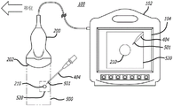
Fig. 4A illustrates a probe connected to a console showing a target vein and a needle, according to some embodiments.
Fig. 4B illustrates a probe connected to a console that displays a target vein and needle in a trimmed image, according to some embodiments.
Fig. 5A illustrates a view of a visualization of a cropped image of a target vein and tracking of a needle projection according to some embodiments.
Fig. 5B illustrates a view of visualization of a cropped image of a target vein and tracking of a needle projection when the detector is shifted, according to some embodiments.
Fig. 5C illustrates a visualization of a cropped image of a target vein and a view showing tracking of a needle tip projection including a movement warning when the detector is displaced, according to some embodiments.
Detailed Description
Before disclosing in greater detail some specific embodiments, it should be understood that the specific embodiments disclosed herein do not limit the scope of the concepts presented herein. It should also be understood that particular embodiments disclosed herein may have features that can be readily separated from the particular embodiments, and optionally combined with or substituted for the features of any of the numerous other embodiments disclosed herein.
With respect to the terms used herein, it is also to be understood that these terms are intended to describe certain specific embodiments, and that these terms are not intended to limit the scope of the concepts provided herein. Ordinals (e.g., first, second, third, etc.) are generally used to distinguish or identify different features or steps in a set of features or steps, and do not provide sequence or numerical limitations. For example, "first," "second," and "third" features or steps need not occur in that order, and particular embodiments that include such features or steps need not be limited to these three features or steps. Labels such as "left", "right", "top", "bottom", "front", "back", and the like are used for convenience and do not imply any particular fixed position, orientation, or direction, for example. Rather, such labels are used to reflect, for example, relative position, orientation, or direction. The singular forms "a", "an" and "the" include plural referents unless the context clearly dictates otherwise.
For clarity, it will be understood that the word "distal" refers to a direction relatively closer to a patient on which the medical device will be used as described herein, while the word "proximal" refers to a direction relatively further away from the patient. Furthermore, the words "comprising," having, "and" with "as used herein, including the claims, are intended to have the same meaning as the word" comprising.
Finally, in the following description, the terms "or" and/or "as used herein are to be interpreted as including or meaning any one or any combination. For example, "A, B or C" or "A, B and/or C" means "any of the following: a; b; c; a and B; a and C; b and C; A. b and C ". An exception to this definition will occur only when a combination of elements, components, functions, steps or acts are in some way inherently mutually exclusive.
Unless defined otherwise, all technical and scientific terms used herein have the same meaning as commonly understood by one of ordinary skill in the art.
Embodiments disclosed herein relate to an ultrasound imaging system for ultrasound imaging while placing a needle into a target vein of a patient. In some embodiments, an ultrasound imaging system is provided that includes image target tracking capabilities. The ultrasound imaging system can provide a consistent ultrasound view throughout the ultrasound guidance process while compensating for inadvertent movement of the ultrasound probe. The exemplary tracking feature advantageously allows for occasional movement of the ultrasound probe during the procedure without the most important imaging data on the screen moving violently. According to an exemplary embodiment, the ultrasound imaging system may be primarily used for insertion of an access device (e.g., a needle). Image tracking provides for accurate placement of the needle into a target vein or another anatomical target despite inadvertent movement of the ultrasound probe.
Referring to fig. 1, a block diagram of an ultrasound imaging system 100 is shown, according to some embodiments. The console 102 may house various components of the ultrasound imaging system 100. A processor 116 and memory 118, such as Random Access Memory (RAM) or non-volatile memory (e.g., electrically erasable programmable read only memory EEPROM), may be included in the console 102 for controlling the functions of the ultrasound imaging system 100 and for performing various logical operations or algorithms during operation of the ultrasound imaging system 100 in accordance with executable instructions 120 stored in the memory 118 for execution by the processor 116. For example, console 102 is configured to instantiate one or more processes by instructions 120 for adjusting the distance of activating ultrasound transducer 148 from a predetermined target (e.g., a target vein) or region, the orientation of activating ultrasound transducer 148 to a predetermined target or region, or both the distance and orientation of activating ultrasound transducer 148 relative to a predetermined target or region, and processing electrical signals from ultrasound probe 106 into an ultrasound image. The activation of the ultrasonic transducer 148 may be adjusted using ultrasonic imaging data, magnetic field data, fiber optic shape sensing data, or a combination thereof received by the console 102. The console 102 may activate some of the ultrasonic transducers in the 2D array of ultrasonic transducers 148 or move the already activated transducers in the linear array of ultrasonic transducers 148.
A digital controller/analog interface 122 may also be included in the console 102 and communicate with the processor 116 and other system components to manage the interface between the ultrasound probe 106 and the other system components described herein. The ultrasound imaging system 100 further includes a port 124 for connecting with additional components, such as optional components 126 including a printer, storage media, keyboard, and the like. The port 124 may be implemented as a Universal Serial Bus (USB) port, although other types of ports may be used for this connection or any other connection shown or described herein. The console 102 includes a power connection 128 to enable an operable connection to an external power source 130. An internal power source 132 (e.g., a battery) may also be used with or without the external power source 130. Power management circuitry 134 is included in the digital controller/analog interface 122 of the console 102 to regulate the use and distribution of power. Alternatively, a separate optical interrogator 154 may be communicatively coupled to console 102 through one of ports 124. Alternatively, console 102 may include an optical interrogator integrated into console 502. Such an optical interrogator is configured to transmit an input optical signal into the accompanying fiber stylet 156 for shape sensing with the ultrasound imaging system 100. The fiber stylet 156, in turn, may be configured to be inserted within a lumen of a medical device, such as a needle, and may transmit an input optical signal from the optical interrogator 154 to a plurality of Fiber Bragg Grating (FBG) sensors along a length of the fiber stylet 156. The optical interrogator 154 may also be configured to receive reflected light signals transmitted by the fiber stylet 156 that are reflected from the plurality of FBG sensors, which may be indicative of the shape of the fiber stylet 156.
The optical interrogator 154 may also be configured to convert the reflected optical signal into a corresponding electrical signal for processing by the console 102 into distance and orientation information relative to the target, and for dynamically adjusting the distance of the activated ultrasound transducer 148, the orientation of the activated ultrasound transducer 148, or both the activated ultrasound transducer 148 distance and orientation relative to the target (e.g., a target vein) or a medical device (e.g., a needle) as the target is approached. For example, the distance and orientation at which the ultrasound transducer 148 is activated may be adjusted relative to the targeted vein. The image plane may be established by activating the ultrasound transducer 148 by being arranged at a particular angle to the target vein based on the orientation of the target vein (e.g., perpendicular or parallel to other configurations). In another embodiment, the image plane may be established by activating the ultrasound transducer 148 perpendicular to the medical device plane including the needle 204 when the medical device (e.g., needle) is in proximity to the ultrasound probe 106. The distance and orientation information may also be used to display an image representation of the medical device on the display.
The display screen 104 may be integrated into (or connected to) the console 102 to provide the clinician with a GUI and display information in the form of ultrasound images of the target acquired by the ultrasound probe 106. Furthermore, the ultrasound imaging system 100 may enable the distance and orientation of a magnetized medical device, such as a needle, to be superimposed in real-time over an ultrasound image of a target, thereby enabling a clinician to accurately guide the magnetized medical device to a predetermined target (e.g., a vein). Alternatively, the display screen 104 may be separate from the console 102 and communicatively (e.g., wirelessly) coupled to the console 102. The console button interface 136 may be used to immediately bring up a desired mode to the display screen 104 by the clinician to provide assistance during an ultrasound-based medical procedure. In some embodiments, the display screen 104 may be implemented as an LCD device. The ultrasound probe 106 may optionally include an Internal Measurement Unit (IMU)158 that may house an accelerometer 160, a gyroscope 162, and a magnetometer 164.
In preparation for inserting a needle or another medical device into a target, the ultrasound probe 106 may be used in conjunction with ultrasound-based visualization of the target, such as a vein. Such visualization gives real-time ultrasound guidance and helps reduce complications commonly associated with such insertions, including inadvertent arterial punctures, hematomas, pneumothorax, and the like. The ultrasound probe 106 may be configured to provide electrical signals corresponding to ultrasound imaging data, magnetic field data, shape sensing data, or a combination thereof to the console 102 for real-time ultrasound needle guidance.
In one embodiment, the object detection logic 166 may be executed by the processor 116 to detect blood vessels and other anatomical objects in the ultrasound image. The target detection logic 166 may include pulse detection logic 168 and component identification logic 170. The target detection logic 166 may use pulse detection logic 168 and component identification logic 170. The pulsation detection logic 168 may compare the image sequences of the blood vessel to detect pulses indicated by periodic changes in blood vessel size (e.g., expansion of the blood vessel diameter). The target detection logic 106 may also detect bone by identifying tissue with a high density based on color saturation in the ultrasound image. The component identification logic 170 may analyze the reflections of the echoes in each ultrasound image. This may be done, for example, using threshold settings to identify organs, blood vessels, and bones. The various logics 166, 168, and 170 may be stored on a non-transitory computer-readable medium of the console 102. Image cropping logic 172 may be executed on processor 116 to crop an image having a detected anatomical target (e.g., a target vein) such that the anatomical target is located at the center of the cropped image, i.e., the center of the entire ultrasound imaging region, as will be discussed in more detail herein. Here, "cropping" may refer to reducing the amount of ultrasound images displayed. Further, cropping may include increasing the magnification of the cropped portion of the ultrasound image. The target detection logic 166 and the image cropping logic 172 may be collectively referred to as "console logic" or "console 102 logic"; however, the term console logic may also include references to any other logic modules shown in FIG. 1.
Referring to fig. 2A, a probe connected to a console is shown according to some embodiments. In this embodiment, the ultrasound probe 200 is connected to the console 102 by a wired connection. In one embodiment, a wireless connection may be used. The ultrasound probe 200 includes a body that can house a console operatively connected to an ultrasound imaging device 220. The ultrasound probe 200 may be configured to assist a user (e.g., a clinician) in inserting an access device (e.g., a needle) into a target vein 210 of a patient. An ultrasound transducer located in the head 202 of the ultrasound probe is configured to capture a 2-D ultrasound image 222 to be displayed on the screen 104 of the console 102. The head 202 may house a linear array of ultrasonic transducers (not shown) or a 2-D array of ultrasonic transducers. The ultrasound transducer may be implemented as a piezoelectric transducer or a Capacitive Micromachined Ultrasound Transducer (CMUT). When the ultrasound probe 200 is configured with a 2-D array of ultrasound transducers, based on the captured ultrasound imaging data, a subset of the ultrasound transducers may be linearly activated as needed for ultrasound imaging.
The transducer may be configured to hold the target in an image plane or to switch to a different image plane (e.g., from a plane perpendicular to the plane of the medical device to a plane parallel to the plane of the medical device) that includes the target. If the ultrasound probe 200 is configured with a movable linear array of ultrasound transducers, the ultrasound transducers may already be activated for ultrasound imaging. For example, based on ultrasound imaging data, a subset of the ultrasound transducers or all available ultrasound transducers may be moved together on the movable linear array as needed for ultrasound imaging to keep the target in the image plane established by the active ultrasound transducers or to switch to a different image plane that includes the target.
The probe 202 may be placed against the patient's skin near the needle insertion site so that an active ultrasound transducer in the probe 202 may generate and emit the generated ultrasound signal as a pulse sequence into the patient. A transmitter (not shown) may then receive the reflected ultrasound signal (i.e., the reflection of the ultrasound pulse generated from the patient's body). The reflected ultrasound signals may be converted into corresponding electrical signals for processing into ultrasound images by the console of the probe 200. Thus, a clinician may use the ultrasound imaging system 100 depicted in fig. 2A to determine a suitable insertion site and establish vascular access to the target vein 210 using a needle or other medical device.
The ultrasound imaging system 100 depicted in fig. 2A is capable of visualizing the target vein 210 in the total available ultrasound image 222 shown on the display 104 of the console 102. In one embodiment, the image data is received from the detector 200 into the console 102 depicted in FIG. 1. The target detection logic 166 may process the image data to render an ultrasound image in the total available ultrasound image 222. As discussed above with reference to fig. 1, the target detection logic 166 may use pulse detection logic 168 and component identification logic 170. The pulsation detection logic 168 may compare the image sequences of the blood vessel to detect pulses indicated by periodic changes in blood vessel size (e.g., expansion of the blood vessel diameter). The component identification logic 170 may also detect bone by identifying tissue having a high density based on color saturation in the ultrasound image. Component identification logic 170 may analyze the reflection of the echo in each image. This can be implemented using thresholds set to define organs, vessels and bones. Various logic may be stored on a non-transitory computer readable medium of console 102. As discussed above, the target detection logic 166 may process the image data including the target vein 210 to render the ultrasound image 222.
The ultrasound imaging system 100 depicted in fig. 2A may be used for insertion procedure site evaluation. Note that while the ultrasound probe assembly depicted in fig. 2A has a general shape, the ultrasound probe 200 may have a different shape as long as the probe captures the insertion site and the target vein 210.
Referring now to fig. 2B, probe 200 is shown connected to console 102, and console 102 displays target vein 210 in cropped image 224 of the total available ultrasound image. As discussed above with reference to fig. 2A, the ultrasound probe 200 is connected to the console 102 by a wired connection. In one embodiment, a wireless connection may be used. The ultrasound probe 200 includes a body that can house a console operatively connected to an ultrasound imaging device 220. The ultrasound probe 200 may be configured to assist a user (e.g., a clinician) in inserting an access device (e.g., a needle) into a target vein 210 of a patient. The probe 202 may be placed against the patient's skin near the needle insertion site so that an active ultrasound transducer in the probe 202 may generate and emit ultrasound signals into the patient as a pulse sequence. A transmitter (not shown) may then receive the reflected ultrasound signal (i.e., the reflection of the ultrasound pulse generated from the patient's body). The reflected ultrasound signals may be converted into corresponding electrical signals for processing into ultrasound images by the console of the probe 200. Thus, a clinician may use the ultrasound imaging system 100 depicted in fig. 2B to determine a suitable insertion site and establish vascular access to the target vein 210 using a needle or other medical device.
The ultrasound imaging system 100 depicted in fig. 2B is capable of imaging and detecting the target vein 210 and providing a visualization as a cropped image 320 shown on the display 104 of the console 102. Cropped image 224 is a subset of the total ultrasound image. In one embodiment, as depicted in FIG. 1, image data is received by console 102 from detector 200. Object detection logic 166 running on console 102 may process the image data to detect an anatomical object (target vein 210) within the ultrasound image.
The target detection logic 166 may use the pulse detection logic 168 and the component identification logic 170 depicted in FIG. 1. The pulsation detection logic 168 may compare the image sequences of the blood vessel to detect pulses indicated by periodic changes in blood vessel size (e.g., expansion of the blood vessel diameter). The component identification logic 170 may also detect bone by identifying tissue having a high density based on color saturation in the ultrasound image. The component identification logic 170 may analyze the reflections of the echoes in each ultrasound image. This may be implemented using a threshold set to define an anatomical target such as an organ, blood vessel, bone, etc. In one embodiment, the image cropping logic 172 depicted in fig. 1 may crop the ultrasound image capturing the imaging region 300 such that the detected anatomical target (e.g., the target vein 210) is located at the center of the cropped image 224. The cropped image 224 then includes the vein 210 in its center and is displayed in the display 104 of the console 102. In addition to cropping the ultrasound image of the captured imaging region 300, the cropped image 224 may be enlarged to fill or substantially fill the display 104. As seen in a comparison of fig. 2A-2B, the image of the target vein 210 in fig. 2B appears larger than the image of the target vein 210 in fig. 2A, indicating that the cropped image 224 has been enlarged.
Referring now to fig. 3A, a display view of a cropped image of a target vein is shown, according to some embodiments. As discussed with reference to fig. 2A-2B, the ultrasound probe 200 includes a body and a head 202, the head 202 housing a transducer that can generate and transmit ultrasound signals into a patient. The ultrasound imaging system 100 depicted in fig. 3A is configured to obtain an ultrasound image, detect a target vein 210 and present a cropped visualization on a display showing the target vein 210. In this embodiment, the ultrasound probe 200 transmits ultrasound pulses such that the ultrasound probe 200 receives reflectance data that includes an imaging region 300 that includes the target vein 210.
The ultrasound image of the imaging region 300 is provided to the console 102, where console logic processes the ultrasound image. In particular, the target detection logic 166 analyzes the ultrasound image to detect the target vein 210. For example, the object detection logic 166 may place a bounding box around the target vein 210 or may detect coordinates of the box around the target vein 210. It should be understood that the term "frame" is not limited to a square or rectangle, but may refer to any other shape, such as a circle, an oval, etc. The image cropping logic 172 then crops the ultrasound image showing the imaging area 300 around the image of the target vein 210 in such a way that the target vein 210 is located in the center of the cropped image 320. For example, when executed by the processor 116, the image cropping logic 172 may crop an ultrasound image showing the imaged area 300 at the bounding box or coordinates determined by the object detection logic 166. The cropped image 320 containing the target vein 210 may then be displayed on the screen of the console 102.
Referring to fig. 3B, a visual view of a cropped image of the target vein when the detector is shifted is shown, according to some embodiments. In this embodiment, the probe 200 is inadvertently displaced in a first direction, e.g., to the left. A displacement of the detector 200 produces a corresponding displacement of the position of the target vein 210 within the imaging region 300, wherein the corresponding displacement of the target vein 210 may be considered to be in a second direction opposite the first direction.
However, according to an exemplary embodiment, the logic of the ultrasound imaging system 100 is configured to detect the target vein 210 and display an image on the console 102, wherein the target vein 210 is displayed in the center of the image (i.e., to compensate for the displacement of the probe 200). Thus, even though the probe 200 may be inadvertently displaced, the image displayed by the console 102 keeps the target vein 210 in the center of the displayed image; thus, the clinician is enabled to continue focusing on the target vein 210 itself, rather than on inadvertent displacement of the probe 200.
In other words, advantageously, cropped image 320 does not change in response to displacement of detector 200. The ultrasound imaging system 100 may identify and distinguish anatomical objects, such as the target vein 210. The ultrasound imaging system 100 may then identify the anatomical target and perform image tracking of the target. The console 102 of the ultrasound imaging system 100 may employ console logic (e.g., the object detection logic 166 and the image cropping logic 172, as described above) to receive a sequence of ultrasound images (or a continuous signal) from the probe 200. Further, the console logic may repeatedly detect the target vein 210 within each image, and may crop the current image for visualization (e.g., as cropped image 320). In this way, the display of the cropped image 320 of the target vein 210 remains unaffected by the displacement of the probe 200, allowing the clinician to advantageously maintain a visual line of sight of the target vein 210.
Referring now to fig. 3C, a display view of a cropped image of a target vein with a movement warning when the detector is shifted is shown, according to some embodiments. In one embodiment, the ultrasound imaging system 100 may maintain and communicate information regarding the location of the identified target vein 210. For example, the console logic may determine that a displacement of the detector 200 has resulted in the target vein 210 being within a threshold distance from an edge of the imaging region 300 and, in response, generate an alert or indication (e.g., alert 322, for example) configured to notify a user (e.g., a clinician) that the target vein 210 may soon be out of view of the detector 200 due to the displacement or movement of the detector 200. In some embodiments, the warning or indication may be a visual warning displayed by console 102, such as warning 322 seen in fig. 3C. The alert 322 may include text, such as "move alert" and/or an indication (e.g., arrow 324) of a direction to move the probe 200 relative to the target vein 210 in order to more centrally locate the ultrasound imaging region 300 on the target vein 210.
For example, the console logic may detect a target vein 210 in each ultrasound image received from the probe 200. When the ultrasound probe 200 is accidentally moved in a manner that the probe 202 is about to stop capturing the target vein 210, the console logic provides a "movement warning" alarm displayed on the display 104, for example as an overlay over the cropped image 320. The console logic may detect the location of the target vein 210 relative to the boundaries of the overall ultrasound image area 300. The visual alarm may be accompanied by an arrow indicating in which way to move the detector away from the edge of the screen. In this way, the clinician is alerted in time before the visualization of the target vein 210 is lost. In one embodiment, the "move alert" alarm may be generated by alarm generation logic of the console logic. In some embodiments, the warning or alarm may be an audio alarm such as a beep. In some embodiments, the warning or alarm may be a vibration of the detector 200, in which case the detector 200 will include a vibration motor communicatively coupled to the console logic. In some embodiments, the warning or alarm may be any combination of a visual alarm, an audio alarm, and/or a vibration.
Referring now to fig. 3D, a view of a warning message displayed on a console display when the probe is displaced and no longer captures the target vein is shown, according to some embodiments. As described above, the ultrasound imaging system 100 may maintain and communicate information regarding the location of the identified target vein 210. For example, the console logic may notify the clinician that the target vein 210 has been moved off-screen in a particular direction, e.g., by analyzing the ultrasound image, failing to detect the target vein 210, and generating a visualization to be presented on the display 104. When the ultrasound probe 200 is moved (shown by the double arrow) in such a way that it no longer captures the target vein 210 (i.e., the target vein is not within the imaging region 300), the console logic may generate an alert configured to be presented on the display 104 for viewing by the clinician.
In the embodiment depicted in fig. 3D, the console logic may analyze each ultrasound image received from the probe 200 in order to detect the target vein 210. When the ultrasound probe 200 is accidentally moved in such a way that the probe 202 no longer captures the target vein 210 (e.g., the target vein 210 is outside the imaging region 300), the console logic provides a "movement warning" alert displayed on the display 104, for example, as an overlay on the cropped image 320. For example, the console logic may provide a "move detector" message alert 326 that is displayed as an overlay on the presentation of the total image area 300. In some embodiments, the console logic may also provide an arrow 324 indicating the direction in which the probe needs to be moved in order to resume capture of the target vein 210. In this way, the clinician is prompted to move the probe and restore visualization of the target vein 210.
Referring to fig. 4A, a probe connected to the console of fig. 2A is shown including imaging of a target vein and needle, according to some embodiments. As described above, the ultrasound probe 200 may be connected to the console 102 via a wired or wireless connection. As shown, the probe 202 may be placed proximate to the needle insertion site against the patient's skin so that an active ultrasound transducer in the probe 202 may generate and emit the generated ultrasound signals as a pulse sequence into the patient. A transmitter (not shown) may then receive the reflected ultrasound signal (i.e., the reflection of the ultrasound pulse generated from the patient's body). The reflected ultrasound signals may be converted into corresponding electrical signals for processing into ultrasound images by the console of the probe 200. Thus, a clinician may use the ultrasound imaging system 100 depicted in fig. 2A to determine a suitable insertion site and establish vascular access to the target vein 210 using the needle 210 or other medical device. Further, the reflected ultrasound signals may include reflections from the needle 404, thereby enabling the ultrasound imaging system 100 to display an ultrasound image showing the imaging region 400.
Referring now to fig. 4B, probe 200 is shown connected to console 102, and console 102 displays a portion of target vein 210 and needle 404 in a cropped image 420 of the total available ultrasound image. As discussed, the ultrasound imaging system 100 may be configured to obtain an ultrasound image showing the ultrasound imaging region 400 and present a cropped image 420 showing a portion of the ultrasound imaging region 400 on the display 104 of the console 102. In some such embodiments, the object detection logic 166 of the console 102 may process the image data (ultrasound reflectance data) to crop the ultrasound image and cause a rendering of the cropped image 420. In particular, the target detection logic 166 may use pulse detection logic 168 and component identification logic 170. The pulsation detection logic 168 may compare image sequences of the blood vessel to detect pulses indicated by periodic changes in the size of the blood vessel (e.g., expansion of the diameter of the blood vessel). The component identification logic 170 may also detect bone by identifying tissue having a high density based on color saturation in the ultrasound image.
Further, in a similar manner, the object detection logic 166 may also be configured to detect the needle with ultrasound images. A needle, such as needle 404, may include certain known reflective characteristics (e.g., size, color saturation, etc.), such that component identification logic 170 of object detection logic 166 may detect and identify the needle in the same manner as discussed with respect to blood vessel and bone detection. Accordingly, the ultrasound probe 200 may be configured to assist a user (e.g., a clinician) in inserting an access device (e.g., a needle 404) into a target vein 210 of a patient. The probe 202 may be placed against the patient's skin near the needle insertion site so that an active ultrasound transducer in the probe 202 may generate and transmit ultrasound signals as a sequence of pulses into the patient. A transmitter (not shown) may then receive the reflected ultrasound signal (i.e., the reflection of the ultrasound pulse generated from the patient's body). The reflected ultrasound signals may be converted into corresponding electrical signals for processing into ultrasound images by the console of the probe 200. Thus, a clinician may use the ultrasound imaging system 100 depicted in fig. 2B to determine a suitable insertion site and establish vascular access to the target vein 210 using the needle 210 or other medical device.
After detecting and identifying the components included within the imaging region 400, the ultrasound imaging system 100 may be configured to generate a cropped image, such as a cropped image 420, that includes the target vein 210 and a portion of the needle 404. In one embodiment, the image cropping logic 172 depicted in fig. 1 may crop an ultrasound image showing the imaging region 400 such that the detected anatomical target (e.g., the target vein 210) is located at the center of the cropped image 420. The cropped image 420 then includes the vein 210 in its center and is displayed on the display 104 of the console 102. In addition to cropping the ultrasound image 300, the cropped image 420 may be enlarged to fill or substantially fill the display 104. As seen in a comparison of fig. 4A-4B, the image of the target vein 210 in fig. 4B appears larger than the image of the target vein 210 in fig. 2A, indicating that the cropped image 420 has been enlarged.
In some embodiments, the determination of the boundary of the ultrasound image from which the crop is shown to image region 400 includes determining the location of needle 404 and its distance from target vein 210. For example, when the needle 404 is very close to the target vein 210, the cropped image 420 may consist of a smaller bounding box around the target vein 210, while when the needle 404 is further away from the target vein 210, the cropped image 420 may consist of a larger bounding box. Thus, in both cases, the cut image 420 shows the target vein 210 and the needle 404. However, in other embodiments, the bounding box on which the cropped image 420 is created is a predetermined size, and the cropping will not take into account the position of the needle 404. As mentioned above, it should be understood that the term "frame" is not limited to a square or rectangle, but may refer to any other shape, such as a circle, an ellipse, etc.
Referring now to fig. 5A, a display view of a cropped image of a portion of a target vein and needle is shown, according to some embodiments. As discussed with reference to fig. 4A-4B, the ultrasound imaging system 100 is configured to obtain ultrasound images, detect the target vein 210 and the needle 404, including the distal tip 501 of the needle 404. Further, the ultrasound imaging system 100 may be configured to present a cropped visualization, such as a cropped image 520, on the display showing the target vein 210 and the needle 404. In some embodiments, tip tracking may be performed using the teachings of one or more of the following U.S. patents: 5,775,322, respectively; 5,879,297; 6,129,668, respectively; 6,216,028, respectively; and 6,263,230, each of which is incorporated by reference herein in its entirety.
Referring to fig. 5B, a visualization view of a cropped image of a portion of a target vein and needle is shown, according to some embodiments. In this embodiment, the probe 200 is inadvertently displaced in a first direction, e.g., to the left. The displacement of the detector 200 may produce a corresponding displacement of the position of the target vein 210 within the imaging region 500, where the corresponding displacement of the target vein 210 may be considered to be in a second direction opposite the first direction. However, according to an exemplary embodiment, no changes occur in the cropped image 520 of the vein 210 and distal tip 501 displayed to the clinician in the cropped image 520 after inadvertent displacement of the probe 200. In other words, advantageously, the cropped image 520 does not change in response to displacement of the detector 200. The ultrasound imaging system 100 may identify and distinguish anatomical objects, such as the target vein 210 and the distal tip 501 of the needle 404, in order to perform image tracking of the distal tip 501. The ultrasound imaging system 100 may employ console logic to receive a sequence of ultrasound images (or a continuous signal) from the probe 200. The console logic may then repeatedly detect the target vein 210 within each image, and may crop the current image for visualization in the cropped image 520. In this way, the target vein 210 displayed in the trimmed image 520 remains unaffected by the displacement of the probe 200. In other words, the focus remains on the target vein 210 and the tracking of the needle tip 501. Thus, advantageously, the clinician does not lose visualization of the target vein 210 and tracking of the distal tip 501.
In other words, advantageously, the cropped image 520 does not change in response to displacement of the detector 200. The ultrasound imaging system 100 may identify and distinguish anatomical objects, such as the target vein 210. The ultrasound imaging system 100 may then identify the anatomical target and perform image tracking of the target. The console 102 of the ultrasound imaging system 100 may employ console logic (e.g., the object detection logic 166 and the image cropping logic 172, as described above) to receive a sequence of ultrasound images (or a continuous signal) from the probe 200. Further, the console logic may repeatedly detect the target vein 210 and needle 404 within each image, and may crop the current image for visualization (e.g., as a cropped image 520). In this way, the display of the cropped image 520 of the target vein 210 remains unaffected by the displacement of the probe 200, allowing the clinician to advantageously maintain a visual line of sight of the target vein 210 and the needle 404 as the needle 404 approaches the target vein 210.
Referring now to fig. 5C, a display view of a cropped image of a portion of a target vein and a needle including a movement warning when a probe is displaced is shown, according to some embodiments. In one embodiment, the ultrasound imaging system 100 may maintain and communicate information about the location of the identified target vein 210. For example, the console logic may determine that the displacement of the probe 200 has caused the distal tip 501 of the needle 404 and/or the target vein 210 to be within a threshold distance from the edge of the imaging region 300 and, in response, generate an alert or indication (e.g., alert 322, for example) configured to notify a user (e.g., a clinician) that the distal tip 501 of the needle 404 or target vein 210 may soon leave the line of sight of the probe 200 due to the displacement or movement of the probe 200. In some embodiments, the warning or indication may be a visual warning displayed by the console 102, such as warning 522 seen in fig. 5C. The alert 522 may include text, such as "move alert" and/or an indication (e.g., arrow 324) of a direction to move the probe 200 relative to the target vein 210 in order to more centrally locate the ultrasound imaging region 500 on the target vein 210.
For example, the console logic may detect the target vein 210 and the needle 404, including the distal tip 501 of the needle 404, in each ultrasound image received from the probe 200. When the ultrasound probe 200 is accidentally moved in such a way that the probe 202 is about to stop capturing the distal tip 501 of the target vein 210 or needle 404, the console logic provides a "movement warning" alarm displayed on the display 104, for example as an overlay on the cropped image 520. The console logic may detect the location of the target vein 210 relative to the boundary of the overall ultrasound image area 500. The visual alarm may be accompanied by an arrow indicating in which way to move the detector away from the edge of the screen. In this way, the clinician is alerted in time before losing visualization of the target vein 210 or the distal tip 501 of the needle 404. In one embodiment, the "move alert" alarm may be generated by alarm generation logic of the console logic. In some embodiments, the warning or alarm may be an audio alarm such as a beep. In some embodiments, the warning or alarm may be a vibration of the detector 200, in which case the detector 200 will include a vibration motor communicatively coupled to the console logic. In some embodiments, the warning or alarm may be any combination of a visual alarm, an audio alarm, and/or a vibration.
Having a system that not only provides ultrasound imaging, but also ensures that the needle is accurately inserted into the target based on the ultrasound image tracking without regard to accidentally displacing the ultrasound probe, advantageously reduces the risk of puncturing the patient's skin in the wrong place or even in multiple places.
Embodiments of the invention may be embodied in other specific forms without departing from the spirit of the disclosure. The described embodiments are to be considered in all respects only as illustrative and not restrictive. The scope of the embodiments is, therefore, indicated by the appended claims rather than by the foregoing description. All changes which come within the meaning and range of equivalency of the claims are to be embraced within their scope.
Claims (30)
1. An ultrasound imaging system, comprising:
an ultrasound probe comprising a transducer array configured to acquire an ultrasound image; and
a console comprising a processor and a non-transitory computer-readable medium having stored thereon a plurality of logic modules that, when executed by the processor, are configured to perform operations comprising:
an ultrasound image is received and,
detecting one or more targets within the ultrasound image, an
A visualization is generated from the ultrasound image to center one or more detection targets within a displayed portion of the ultrasound image.
2. The ultrasound imaging system of claim 1, wherein generating the visualization comprises cropping the ultrasound image to center the one or more detection targets within a displayed portion of the ultrasound image.
3. The ultrasound imaging system of claim 2, wherein generating the visualization comprises increasing a magnification of a cropped portion of the ultrasound image to center the one or more detection targets within a displayed portion of the ultrasound image.
4. The ultrasound imaging system of claim 1, wherein the ultrasound probe is operatively connected to the console via a wired connection or a wireless connection.
5. The ultrasound imaging system of claim 1, wherein the console comprises a display, and wherein the plurality of logic modules, when executed by the processor, are configured to perform further operations comprising: a visualization of the cropped ultrasound image is presented on the display.
6. The ultrasound imaging system of claim 1, wherein detecting the one or more targets comprises differentiating components within the ultrasound image according to changing color saturation within the ultrasound image.
7. The ultrasound imaging system of claim 1, wherein detecting the one or more targets comprises identifying each of the one or more targets as a blood vessel, a bone, an organ, or a medical device.
8. The ultrasound imaging system of claim 7, wherein identifying each of the one or more targets includes comparing the characteristics of each of the one or more targets to a threshold set to define an organ, a blood vessel, a bone, or a medical device.
9. The ultrasound imaging system of claim 8, wherein the features include one or more of a pulsation detected while analyzing the ultrasound image and a previous ultrasound image, a size of each of the one or more targets, and a color saturation of each of the one or more targets.
10. The ultrasound imaging system of claim 9, wherein the comparison of the feature to one or more thresholds results in each of the one or more targets indicating a confidence in the likelihood of identifying a selected target.
11. The ultrasound imaging system of claim 1, wherein the plurality of logic modules, when executed by the processor, are configured to perform further operations comprising: detecting that at least a first target of the one or more targets is within a threshold distance of an edge of the ultrasound image.
12. The ultrasound imaging system of claim 11, wherein the plurality of logic modules, when executed by the processor, are configured to perform further operations comprising: generating an alert indicating to a clinician that the first target is within a threshold of an edge of the ultrasound image.
13. The ultrasound imaging system of claim 12, wherein the alert comprises a text notification or an arrow indicating a direction to move the ultrasound probe.
14. The ultrasound imaging system of claim 1, wherein the one or more targets include a blood vessel and a needle.
15. The ultrasound imaging system of claim 14, wherein the one or more targets comprise a distal tip of the needle.
16. A method for obtaining an ultrasound image by an ultrasound imaging system, the ultrasound imaging system comprising an ultrasound probe including a transducer array configured to acquire an ultrasound image and a console including a processor and a non-transitory computer readable medium having stored thereon a plurality of logic modules configured to perform operations when executed by the processor, the method comprising:
receiving, by the console, an ultrasound image acquired by the ultrasound probe;
detecting one or more targets within the ultrasound image; and
a visualization is generated from the ultrasound image to center one or more detection targets within a displayed portion of the ultrasound image.
17. The method of claim 16, wherein generating the visualization comprises cropping the ultrasound image to center the one or more detection targets within a displayed portion of the ultrasound image.
18. The method of claim 17, wherein generating the visualization includes increasing a magnification of a cropped portion of the ultrasound image to center the one or more detected objects within the displayed portion of the ultrasound image.
19. The method of claim 16, wherein the ultrasound probe is operatively connected to the console via a wired connection or a wireless connection.
20. The method of claim 16, wherein the console comprises a display, and wherein the plurality of logic modules, when executed by the processor, are configured to perform further operations comprising: a visualization of the cropped ultrasound image is presented on the display.
21. The method of claim 16, wherein detecting the one or more objects comprises differentiating components within the ultrasound image according to changing color saturation within the ultrasound image.
22. The method of claim 16, wherein detecting the one or more targets comprises identifying each of the one or more targets as a vessel, a bone, an organ, or a medical device.
23. The method of claim 22, wherein identifying each of the one or more targets comprises comparing the characteristic of each of the one or more targets to a threshold set to define an organ, a blood vessel, a bone, or a medical device.
24. The method of claim 23, wherein the features include one or more of a pulsation detected while analyzing the ultrasound image and a previous ultrasound image, a size of each of the one or more targets, and a color saturation of each of the one or more targets.
25. The method of claim 24, wherein the result of comparing the feature to one or more thresholds is that each of the one or more targets indicates a confidence level in the likelihood of identifying the selected target.
26. The method of claim 16, wherein the plurality of logic modules, when executed by the processor, are configured to perform further operations comprising: detecting that at least a first target of the one or more targets is within a threshold distance of an edge of the ultrasound image.
27. The method of claim 26, wherein the plurality of logic modules, when executed by the processor, are configured to perform further operations comprising: generating an alert indicating to a clinician that the first target is within a threshold of an edge of the ultrasound image.
28. The method of claim 27, wherein the alert comprises a text notification or an arrow indicating a direction to move the ultrasound probe.
29. The method of claim 16, wherein the one or more targets comprise a blood vessel and a needle.
30. The method of claim 29, wherein the one or more targets comprise a distal tip of the needle.
Applications Claiming Priority (2)
| Application Number | Priority Date | Filing Date | Title |
|---|---|---|---|
| US202063119829P | 2020-12-01 | 2020-12-01 | |
| US63/119,829 | 2020-12-01 |
Publications (1)
| Publication Number | Publication Date |
|---|---|
| CN114569155A true CN114569155A (en) | 2022-06-03 |
Family
ID=79164547
Family Applications (1)
| Application Number | Title | Priority Date | Filing Date |
|---|---|---|---|
| CN202111443175.6A Pending CN114569155A (en) | 2020-12-01 | 2021-11-30 | Ultrasound imaging system and method for obtaining ultrasound image by the same |
Country Status (4)
| Country | Link |
|---|---|
| US (1) | US12048491B2 (en) |
| EP (1) | EP4251063A1 (en) |
| CN (1) | CN114569155A (en) |
| WO (1) | WO2022119853A1 (en) |
Families Citing this family (5)
| Publication number | Priority date | Publication date | Assignee | Title |
|---|---|---|---|---|
| CA3152545A1 (en) | 2019-09-20 | 2021-03-25 | Bard Access Systems, Inc. | Automatic vessel detection tools and methods |
| CN216135922U (en) | 2020-09-08 | 2022-03-29 | 巴德阿克塞斯系统股份有限公司 | Dynamically adjusting an ultrasound imaging system |
| US12048491B2 (en) | 2020-12-01 | 2024-07-30 | Bard Access Systems, Inc. | Ultrasound probe with target tracking capability |
| US12102481B2 (en) | 2022-06-03 | 2024-10-01 | Bard Access Systems, Inc. | Ultrasound probe with smart accessory |
| WO2024010940A1 (en) * | 2022-07-08 | 2024-01-11 | Bard Access Systems, Inc. | Systems and methods for intelligent ultrasound probe guidance |
Family Cites Families (336)
| Publication number | Priority date | Publication date | Assignee | Title |
|---|---|---|---|---|
| US3697917A (en) | 1971-08-02 | 1972-10-10 | Gen Electric | Semiconductor strain gage pressure transducer |
| US5148809A (en) | 1990-02-28 | 1992-09-22 | Asgard Medical Systems, Inc. | Method and apparatus for detecting blood vessels and displaying an enhanced video image from an ultrasound scan |
| FR2662813B1 (en) | 1990-05-29 | 1992-08-14 | Traitement Synthese Image | PROCESS FOR ACQUIRING ECHOGRAPHY IMAGES. |
| US5325293A (en) | 1992-02-18 | 1994-06-28 | Dorne Howard L | System and method for correlating medical procedures and medical billing codes |
| US5441052A (en) | 1992-12-28 | 1995-08-15 | Kabushiki Kaisha Toshiba | Color doppler-type ultrasonic diagnostic apparatus |
| US5349865A (en) | 1993-08-30 | 1994-09-27 | Kavlico Corporation | Wide-pressure-range, adaptable, simplified pressure transducer |
| US5549554A (en) | 1994-04-01 | 1996-08-27 | Advanced Cardiovascular Systems, Inc. | Catheters having separable reusable components |
| US5573529A (en) | 1994-10-31 | 1996-11-12 | Haak; Benjamin A. | Color coded medical instruments |
| US6019724A (en) | 1995-02-22 | 2000-02-01 | Gronningsaeter; Aage | Method for ultrasound guidance during clinical procedures |
| EP0835075A4 (en) | 1995-06-30 | 1999-06-23 | Boston Scient Corp | Ultrasound imaging catheter with a cutting element |
| US6375615B1 (en) | 1995-10-13 | 2002-04-23 | Transvascular, Inc. | Tissue penetrating catheters having integral imaging transducers and their methods of use |
| US5908387A (en) | 1996-06-21 | 1999-06-01 | Quinton Instrument Company | Device and method for improved quantitative coronary artery analysis |
| US5775322A (en) | 1996-06-27 | 1998-07-07 | Lucent Medical Systems, Inc. | Tracheal tube and methods related thereto |
| US5879297A (en) | 1997-05-08 | 1999-03-09 | Lucent Medical Systems, Inc. | System and method to determine the location and orientation of an indwelling medical device |
| US6263230B1 (en) | 1997-05-08 | 2001-07-17 | Lucent Medical Systems, Inc. | System and method to determine the location and orientation of an indwelling medical device |
| US6129668A (en) | 1997-05-08 | 2000-10-10 | Lucent Medical Systems, Inc. | System and method to determine the location and orientation of an indwelling medical device |
| CA2240757C (en) | 1997-07-14 | 2001-08-28 | Matsushita Electric Industrial Co., Ltd. | Blood vessel puncturing device |
| US5897503A (en) | 1997-08-01 | 1999-04-27 | Acuson Corporation | Ultrasound transducer probe having case handle grip surfaces |
| EP1019134B1 (en) | 1997-10-01 | 2004-04-14 | Boston Scientific Limited | Kit for use in preinsertion measurement of catheters |
| US5970119A (en) | 1997-11-18 | 1999-10-19 | Douglas Holtz (Part Interest) | Radiological scaling and alignment device |
| US20030135115A1 (en) | 1997-11-24 | 2003-07-17 | Burdette Everette C. | Method and apparatus for spatial registration and mapping of a biopsy needle during a tissue biopsy |
| KR100255730B1 (en) | 1997-12-15 | 2000-05-01 | 이민화 | Ultrasonic color doppler system for displaying artery and vein |
| US6231546B1 (en) | 1998-01-13 | 2001-05-15 | Lumend, Inc. | Methods and apparatus for crossing total occlusions in blood vessels |
| US7713190B2 (en) | 1998-02-24 | 2010-05-11 | Hansen Medical, Inc. | Flexible instrument |
| US6004270A (en) | 1998-06-24 | 1999-12-21 | Ecton, Inc. | Ultrasound system for contrast agent imaging and quantification in echocardiography using template image for image alignment |
| US6132379A (en) | 1998-11-04 | 2000-10-17 | Patacsil; Estelito G. | Method and apparatus for ultrasound guided intravenous cannulation |
| US6524249B2 (en) | 1998-11-11 | 2003-02-25 | Spentech, Inc. | Doppler ultrasound method and apparatus for monitoring blood flow and detecting emboli |
| IL127112A0 (en) | 1998-11-18 | 1999-09-22 | Biosonix Ltd | System for measuring flow and method therefor |
| JP2000271136A (en) | 1999-03-25 | 2000-10-03 | Toshiba Corp | Ultrasonic therapeutic apparatus and method for controlling the same |
| US6233476B1 (en) | 1999-05-18 | 2001-05-15 | Mediguide Ltd. | Medical positioning system |
| US7534209B2 (en) | 2000-05-26 | 2009-05-19 | Physiosonics, Inc. | Device and method for mapping and tracking blood flow and determining parameters of blood flow |
| AU768362B2 (en) | 1999-06-05 | 2003-12-11 | Cook Medical Technologies Llc | Indicia for an endoscopic medical device |
| US6687386B1 (en) | 1999-06-15 | 2004-02-03 | Hitachi Denshi Kabushiki Kaisha | Object tracking method and object tracking apparatus |
| WO2001010295A1 (en) | 1999-08-06 | 2001-02-15 | The Board Of Regents Of The University Of Texas System | Optoacoustic monitoring of blood oxygenation |
| US6251073B1 (en) | 1999-08-20 | 2001-06-26 | Novasonics, Inc. | Miniaturized ultrasound apparatus and method |
| EP1152694B1 (en) | 1999-12-07 | 2004-07-21 | Koninklijke Philips Electronics N.V. | Ultrasonic image processing method and system for displaying a composite image sequence of an artery segment |
| EP1157285A1 (en) | 1999-12-21 | 2001-11-28 | Koninklijke Philips Electronics N.V. | Ultrasonic image processing method and examination system for displaying an ultrasonic composite image sequence of an artery |
| WO2001047421A1 (en) | 1999-12-28 | 2001-07-05 | Koninklijke Philips Electronics N.V. | Ultrasonic image processing method and system for displaying an ultrasonic color-coded image sequence of an object having moving parts |
| US6612992B1 (en) | 2000-03-02 | 2003-09-02 | Acuson Corp | Medical diagnostic ultrasound catheter and method for position determination |
| US6554774B1 (en) | 2000-03-23 | 2003-04-29 | Tensys Medical, Inc. | Method and apparatus for assessing hemodynamic properties within the circulatory system of a living subject |
| US6640976B1 (en) | 2000-06-13 | 2003-11-04 | Careguide, Inc. | Male clean intermittent catheter system |
| US6524246B1 (en) | 2000-10-13 | 2003-02-25 | Sonocine, Inc. | Ultrasonic cellular tissue screening tool |
| US7831449B2 (en) | 2001-02-02 | 2010-11-09 | Thompson Reuters (Healthcare) Inc. | Method and system for extracting medical information for presentation to medical providers on mobile terminals |
| US6592565B2 (en) | 2001-04-26 | 2003-07-15 | Zbylut J. Twardowski | Patient-tailored, central-vein catheters |
| ES2357099T3 (en) | 2001-05-23 | 2011-04-18 | Radi Medical Systems Ab | INTERACTIVE MEASUREMENT SYSTEM. |
| US7217266B2 (en) | 2001-05-30 | 2007-05-15 | Anderson R Rox | Apparatus and method for laser treatment with spectroscopic feedback |
| US6592520B1 (en) | 2001-07-31 | 2003-07-15 | Koninklijke Philips Electronics N.V. | Intravascular ultrasound imaging apparatus and method |
| WO2003022169A1 (en) | 2001-09-12 | 2003-03-20 | Scimed Life Systems, Inc. | System for identifying medical devices |
| US6543642B1 (en) | 2001-09-21 | 2003-04-08 | Daydots International, Inc. | Disposable glove dispenser system |
| US6733458B1 (en) | 2001-09-25 | 2004-05-11 | Acuson Corporation | Diagnostic medical ultrasound systems and methods using image based freehand needle guidance |
| JP3863414B2 (en) | 2001-11-22 | 2006-12-27 | 株式会社東芝 | Ultrasonic diagnostic equipment |
| US6689067B2 (en) | 2001-11-28 | 2004-02-10 | Siemens Corporate Research, Inc. | Method and apparatus for ultrasound guidance of needle biopsies |
| US6601705B2 (en) | 2001-12-07 | 2003-08-05 | The Procter & Gamble Company | Package containing a window and performance characteristic indicator |
| US6554771B1 (en) | 2001-12-18 | 2003-04-29 | Koninklijke Philips Electronics N.V. | Position sensor in ultrasound transducer probe |
| US6746402B2 (en) | 2002-01-02 | 2004-06-08 | E. Tuncay Ustuner | Ultrasound system and method |
| US6755789B2 (en) | 2002-02-05 | 2004-06-29 | Inceptio Medical Technologies, Llc | Ultrasonic vascular imaging system and method of blood vessel cannulation |
| JP4217023B2 (en) | 2002-02-25 | 2009-01-28 | 一郎 佐久間 | Vascular endothelial measuring device |
| US7734326B2 (en) | 2002-06-20 | 2010-06-08 | Brainlab Ag | Method and device for preparing a drainage |
| US7359554B2 (en) | 2002-08-26 | 2008-04-15 | Cleveland Clinic Foundation | System and method for identifying a vascular border |
| US7697972B2 (en) | 2002-11-19 | 2010-04-13 | Medtronic Navigation, Inc. | Navigation system for cardiac therapies |
| US7599730B2 (en) | 2002-11-19 | 2009-10-06 | Medtronic Navigation, Inc. | Navigation system for cardiac therapies |
| US7925327B2 (en) | 2002-12-04 | 2011-04-12 | Koninklijke Philips Electronics N.V. | Apparatus and method for assisting the navigation of a catheter in a vessel |
| US7927278B2 (en) | 2002-12-13 | 2011-04-19 | California Institute Of Technology | Split-screen display system and standardized methods for ultrasound image acquisition and multi-frame data processing |
| US7074187B2 (en) | 2002-12-13 | 2006-07-11 | Selzer Robert H | System and method for improving ultrasound image acquisition and replication for repeatable measurements of vascular structures |
| US6979294B1 (en) | 2002-12-13 | 2005-12-27 | California Institute Of Technology | Split-screen display system and standardized methods for ultrasound image acquisition and processing for improved measurements of vascular structures |
| JP2006510412A (en) | 2002-12-18 | 2006-03-30 | コーニンクレッカ フィリップス エレクトロニクス エヌ ヴィ | Ultrasound device for estimating arterial parameters |
| AU2003303048A1 (en) | 2002-12-18 | 2004-07-09 | Koninklijke Philips Electronics N.V. | Ultrasonic doppler system for determining movement of artery walls |
| US6749569B1 (en) | 2003-01-07 | 2004-06-15 | Esaote S.P.A. | Method and apparatus for ultrasound imaging |
| JP4607859B2 (en) | 2003-02-19 | 2011-01-05 | サイセル・テクノロジーズ,インコーポレイテッド | In vivo fluorescent sensor, system and related methods operating in conjunction with a fluorescent analyte |
| US7727153B2 (en) | 2003-04-07 | 2010-06-01 | Sonosite, Inc. | Ultrasonic blood vessel measurement apparatus and method |
| USD496596S1 (en) | 2003-04-30 | 2004-09-28 | Robert Dalrymple | Image french measuring adjunct |
| JP4401354B2 (en) | 2003-05-19 | 2010-01-20 | 株式会社日立製作所 | Ultrasonic therapy device |
| US20050000975A1 (en) | 2003-05-28 | 2005-01-06 | Carco Darlene Marie | Sterile surgical glove dispenser |
| WO2005002446A1 (en) | 2003-07-03 | 2005-01-13 | Matsushita Electric Industrial Co., Ltd. | Ultrasonic diagnostic system |
| TWI221407B (en) | 2003-08-27 | 2004-10-01 | Micro Star Int Co Ltd | Device and method for detecting the location of vein by ultrasound |
| JP4698589B2 (en) | 2003-09-04 | 2011-06-08 | コーニンクレッカ フィリップス エレクトロニクス エヌ ヴィ | Apparatus and method for displaying ultrasound image of blood vessel |
| US7244234B2 (en) | 2003-11-11 | 2007-07-17 | Soma Development Llc | Ultrasound guided probe device and method of using same |
| ATE482664T1 (en) | 2004-01-20 | 2010-10-15 | Koninkl Philips Electronics Nv | DEVICE AND METHOD FOR NAVIGATING A CATHETER |
| US7787936B2 (en) | 2004-01-23 | 2010-08-31 | Traxyz Medical, Inc. | Methods and apparatus for performing procedures on target locations in the body |
| US9681925B2 (en) | 2004-04-21 | 2017-06-20 | Siemens Medical Solutions Usa, Inc. | Method for augmented reality instrument placement using an image based navigation system |
| US8014848B2 (en) | 2004-04-26 | 2011-09-06 | Brainlab Ag | Visualization of procedural guidelines for a medical procedure |
| DE602004013926D1 (en) | 2004-04-26 | 2008-07-03 | Brainlab Ag | Visualization of procedural guidelines for medical procedures |
| US20050267365A1 (en) | 2004-06-01 | 2005-12-01 | Alexander Sokulin | Method and apparatus for measuring anatomic structures |
| JP4648652B2 (en) | 2004-06-24 | 2011-03-09 | テルモ株式会社 | Ultrasonic diagnostic apparatus and method for operating ultrasonic diagnostic apparatus |
| US20060004290A1 (en) | 2004-06-30 | 2006-01-05 | Smith Lowell S | Ultrasound transducer with additional sensors |
| US20060020204A1 (en) * | 2004-07-01 | 2006-01-26 | Bracco Imaging, S.P.A. | System and method for three-dimensional space management and visualization of ultrasound data ("SonoDEX") |
| US20060013523A1 (en) | 2004-07-16 | 2006-01-19 | Luna Innovations Incorporated | Fiber optic position and shape sensing device and method relating thereto |
| US20060015039A1 (en) | 2004-07-19 | 2006-01-19 | Cassidy Kenneth T | Guidewire bearing markings simplifying catheter selection |
| US7426497B2 (en) | 2004-08-31 | 2008-09-16 | Microsoft Corporation | Method and apparatus for analysis and decomposition of classifier data anomalies |
| US8016758B2 (en) * | 2004-10-30 | 2011-09-13 | Sonowise, Inc. | User interface for medical imaging including improved pan-zoom control |
| CN100539951C (en) | 2004-11-17 | 2009-09-16 | 株式会社日立医药 | Diagnostic ultrasound equipment |
| US7720520B2 (en) | 2004-12-01 | 2010-05-18 | Boston Scientific Scimed, Inc. | Method and system for registering an image with a navigation reference catheter |
| US20060184029A1 (en) * | 2005-01-13 | 2006-08-17 | Ronen Haim | Ultrasound guiding system and method for vascular access and operation mode |
| US7918787B2 (en) | 2005-02-02 | 2011-04-05 | Voyage Medical, Inc. | Tissue visualization and manipulation systems |
| JPWO2006082966A1 (en) | 2005-02-07 | 2008-06-26 | 松下電器産業株式会社 | Ultrasonic diagnostic equipment |
| US7892177B2 (en) | 2005-02-28 | 2011-02-22 | Scimed Life Systems, Inc. | Systems and methods for estimating the length and position of a stent to be applied within a patient |
| JP5484674B2 (en) | 2005-03-04 | 2014-05-07 | シー・アール・バード・インコーポレーテッド | Access port and identification method |
| US20090306509A1 (en) | 2005-03-30 | 2009-12-10 | Worcester Polytechnic Institute | Free-hand three-dimensional ultrasound diagnostic imaging with position and angle determination sensors |
| US7680307B2 (en) | 2005-04-05 | 2010-03-16 | Scimed Life Systems, Inc. | Systems and methods for image segmentation with a multi-stage classifier |
| ES2425388T3 (en) | 2005-05-06 | 2013-10-15 | Vasonova, Inc. | Apparatus for guiding and positioning an endovascular device |
| WO2006119572A1 (en) | 2005-05-12 | 2006-11-16 | Compumedics Medical Innovation Pty Ltd | Ultrasound diagnosis and treatment apparatus |
| US8298147B2 (en) | 2005-06-24 | 2012-10-30 | Volcano Corporation | Three dimensional co-registration for intravascular diagnosis and therapy |
| US7681579B2 (en) | 2005-08-02 | 2010-03-23 | Biosense Webster, Inc. | Guided procedures for treating atrial fibrillation |
| US8147408B2 (en) | 2005-08-31 | 2012-04-03 | Sonosite, Inc. | Medical device guide locator |
| US8852111B2 (en) | 2005-09-02 | 2014-10-07 | Ultrasound Ventures, Llc | Ultrasound guidance system |
| WO2007047566A2 (en) | 2005-10-14 | 2007-04-26 | The Cleveland Clinic Foundation | System and method for characterizing vascular tissue |
| US8303505B2 (en) | 2005-12-02 | 2012-11-06 | Abbott Cardiovascular Systems Inc. | Methods and apparatuses for image guided medical procedures |
| US8105239B2 (en) | 2006-02-06 | 2012-01-31 | Maui Imaging, Inc. | Method and apparatus to visualize the coronary arteries using ultrasound |
| JP4812460B2 (en) | 2006-02-22 | 2011-11-09 | 株式会社ユネクス | Arterial blood vessel determination method and apparatus |
| US20070199848A1 (en) | 2006-02-28 | 2007-08-30 | Ellswood Mark R | Packaging with color-coded identification |
| US8060181B2 (en) | 2006-04-07 | 2011-11-15 | Brainlab Ag | Risk assessment for planned trajectories |
| WO2007122698A1 (en) | 2006-04-18 | 2007-11-01 | Panasonic Corporation | Ultrasonograph |
| US8112292B2 (en) | 2006-04-21 | 2012-02-07 | Medtronic Navigation, Inc. | Method and apparatus for optimizing a therapy |
| ES2524303T3 (en) | 2006-05-08 | 2014-12-05 | C.R. Bard, Inc. | User interface and methods for an ultrasound presentation device |
| US20080021322A1 (en) | 2006-05-24 | 2008-01-24 | Michael Benjamin Stone | Ultrasonic imaging apparatus and method |
| US20080033759A1 (en) | 2006-08-02 | 2008-02-07 | Vastrac, Inc. | Information manager for a procedure-based medical practice |
| JP5336369B2 (en) | 2006-08-11 | 2013-11-06 | コーニンクレッカ フィリップス エヌ ヴェ | Ultrasound system for cerebral blood flow imaging and microbubble improvement thrombus resolution |
| JP4886432B2 (en) | 2006-09-04 | 2012-02-29 | ジーイー・メディカル・システムズ・グローバル・テクノロジー・カンパニー・エルエルシー | Ultrasonic diagnostic equipment |
| US8478377B2 (en) | 2006-10-04 | 2013-07-02 | Dexcom, Inc. | Analyte sensor |
| US20080146915A1 (en) | 2006-10-19 | 2008-06-19 | Mcmorrow Gerald | Systems and methods for visualizing a cannula trajectory |
| WO2008057478A2 (en) | 2006-11-03 | 2008-05-15 | The Regents Of The University Of Michigan | Method and system for determining volume flow in a blood conduit |
| US20080177186A1 (en) | 2007-01-18 | 2008-07-24 | Slater Charles R | Methods and Apparatus for Determining a Treatment Volume of a Fluid Treatment Agent for Treating The Interior of a Blood Vessel |
| US20080188752A1 (en) | 2007-02-05 | 2008-08-07 | Penrith Corporation | Automated movement detection with audio and visual information |
| WO2008100386A2 (en) | 2007-02-09 | 2008-08-21 | Board Of Regents, The University Of Texas System | Intravascular photoacoustic and ultrasound echo imaging |
| US8781193B2 (en) | 2007-03-08 | 2014-07-15 | Sync-Rx, Ltd. | Automatic quantitative vessel analysis |
| US11197651B2 (en) * | 2007-03-08 | 2021-12-14 | Sync-Rx, Ltd. | Identification and presentation of device-to-vessel relative motion |
| US10433929B2 (en) | 2007-03-09 | 2019-10-08 | St. Jude Medical, Atrial Fibrillation Division, Inc. | System and method for local deformable registration of a catheter navigation system to image data or a model |
| US8038619B2 (en) | 2007-04-30 | 2011-10-18 | General Electric Company | Motor driver for ultrasound system |
| JP2010527678A (en) | 2007-05-23 | 2010-08-19 | オスシロン リミテッド | Apparatus and method for guided penetration of chronic total occlusion |
| US7976469B2 (en) | 2007-06-04 | 2011-07-12 | Medtronic, Inc. | Percutaneous needle guide |
| US8702609B2 (en) | 2007-07-27 | 2014-04-22 | Meridian Cardiovascular Systems, Inc. | Image-guided intravascular therapy catheters |
| US8073215B2 (en) | 2007-09-18 | 2011-12-06 | Siemens Medical Solutions Usa, Inc. | Automated detection of planes from three-dimensional echocardiographic data |
| US8818472B2 (en) | 2007-09-28 | 2014-08-26 | University Of Florida Research Foundation, Inc. | Methods and devices for noninvasive measurement of energy absorbers in blood |
| US8323202B2 (en) | 2007-11-16 | 2012-12-04 | Pneumrx, Inc. | Method and system for measuring pulmonary artery circulation information |
| US8388541B2 (en) | 2007-11-26 | 2013-03-05 | C. R. Bard, Inc. | Integrated system for intravascular placement of a catheter |
| US10449330B2 (en) | 2007-11-26 | 2019-10-22 | C. R. Bard, Inc. | Magnetic element-equipped needle assemblies |
| US8849382B2 (en) | 2007-11-26 | 2014-09-30 | C. R. Bard, Inc. | Apparatus and display methods relating to intravascular placement of a catheter |
| US9649048B2 (en) | 2007-11-26 | 2017-05-16 | C. R. Bard, Inc. | Systems and methods for breaching a sterile field for intravascular placement of a catheter |
| US9521961B2 (en) | 2007-11-26 | 2016-12-20 | C. R. Bard, Inc. | Systems and methods for guiding a medical instrument |
| US10524691B2 (en) | 2007-11-26 | 2020-01-07 | C. R. Bard, Inc. | Needle assembly including an aligned magnetic element |
| US8781555B2 (en) | 2007-11-26 | 2014-07-15 | C. R. Bard, Inc. | System for placement of a catheter including a signal-generating stylet |
| US10751509B2 (en) | 2007-11-26 | 2020-08-25 | C. R. Bard, Inc. | Iconic representations for guidance of an indwelling medical device |
| US8073529B2 (en) | 2007-12-04 | 2011-12-06 | Civco Medical Instruments Co., Inc. | Needle guide system for use with ultrasound transducers to effect shallow path needle entry and method of use |
| US20090143672A1 (en) | 2007-12-04 | 2009-06-04 | Harms Steven E | Method for mapping image reference points to facilitate biopsy using magnetic resonance imaging |
| US20090281413A1 (en) | 2007-12-18 | 2009-11-12 | Searete Llc, A Limited Liability Corporation Of The State Of Delaware | Systems, devices, and methods for detecting occlusions in a biological subject |
| US8172753B2 (en) * | 2008-07-11 | 2012-05-08 | General Electric Company | Systems and methods for visualization of an ultrasound probe relative to an object |
| US9022940B2 (en) | 2008-07-18 | 2015-05-05 | Joseph H. Meier | Handheld imaging devices and related methods |
| US20100063400A1 (en) | 2008-09-05 | 2010-03-11 | Anne Lindsay Hall | Method and apparatus for catheter guidance using a combination of ultrasound and x-ray imaging |
| US20120179044A1 (en) | 2009-09-30 | 2012-07-12 | Alice Chiang | Ultrasound 3d imaging system |
| WO2010029521A2 (en) | 2008-09-15 | 2010-03-18 | Moshe Ben Chorin | Vein locator and associated devices |
| US8200313B1 (en) | 2008-10-01 | 2012-06-12 | Bioquantetics, Inc. | Application of image-based dynamic ultrasound spectrography in assisting three dimensional intra-body navigation of diagnostic and therapeutic devices |
| US10863970B2 (en) | 2008-12-18 | 2020-12-15 | C. R. Bard, Inc. | Needle guide including enhanced visibility entrance |
| WO2010076808A1 (en) | 2008-12-31 | 2010-07-08 | Larsen & Tourbo Limited | Integrated ultrasound imaging device with pulse oximeter waveform display for application of regional anesthesia |
| US20100249598A1 (en) | 2009-03-25 | 2010-09-30 | General Electric Company | Ultrasound probe with replaceable head portion |
| US8355554B2 (en) * | 2009-04-14 | 2013-01-15 | Sonosite, Inc. | Systems and methods for adaptive volume imaging |
| US8781194B2 (en) | 2009-04-17 | 2014-07-15 | Tufts Medical Center, Inc. | Aneurysm detection |
| EP2429405B1 (en) | 2009-05-13 | 2018-07-18 | Koninklijke Philips N.V. | Ultrasonic blood flow doppler audio with pitch shifting |
| US8556815B2 (en) | 2009-05-20 | 2013-10-15 | Laurent Pelissier | Freehand ultrasound imaging systems and methods for guiding fine elongate instruments |
| US20100312121A1 (en) | 2009-06-09 | 2010-12-09 | Zhonghui Guan | Apparatus for a needle director for an ultrasound transducer probe |
| US20100324418A1 (en) | 2009-06-23 | 2010-12-23 | Essa El-Aklouk | Ultrasound transducer |
| US20110002518A1 (en) | 2009-07-01 | 2011-01-06 | General Electric Company | Method and system for processing ultrasound data |
| CN102469988B (en) | 2009-07-16 | 2014-12-03 | 尤奈克斯公司 | Ultrasonic blood vessel examination apparatus |
| KR101121286B1 (en) * | 2009-07-31 | 2012-03-23 | 한국과학기술원 | Ultrasound system and method for performing calibration of sensor |
| WO2011038044A2 (en) | 2009-09-23 | 2011-03-31 | Lightlab Imaging, Inc. | Lumen morphology and vascular resistance measurements data collection systems, apparatus and methods |
| EP2482719A4 (en) | 2009-09-29 | 2016-03-09 | Bard Inc C R | Stylets for use with apparatus for intravascular placement of a catheter |
| JP2011072585A (en) | 2009-09-30 | 2011-04-14 | Fujifilm Corp | Ultrasonic probe |
| WO2011044421A1 (en) | 2009-10-08 | 2011-04-14 | C. R. Bard, Inc. | Spacers for use with an ultrasound probe |
| US10639008B2 (en) | 2009-10-08 | 2020-05-05 | C. R. Bard, Inc. | Support and cover structures for an ultrasound probe head |
| US20140180116A1 (en) | 2009-10-08 | 2014-06-26 | C. R. Bard, Inc. | Coupling Structures for an Ultrasound Probe |
| ES2552372T3 (en) | 2009-12-03 | 2015-11-27 | Deltex Medical Limited | Method and apparatus for hemodynamic control using combined measurement of blood flow and blood pressure |
| US9445780B2 (en) | 2009-12-04 | 2016-09-20 | University Of Virginia Patent Foundation | Tracked ultrasound vessel imaging |
| JP5672241B2 (en) | 2009-12-18 | 2015-02-18 | コニカミノルタ株式会社 | Ultrasonic diagnostic apparatus and control method thereof |
| WO2011085135A1 (en) | 2010-01-07 | 2011-07-14 | Verathon Inc. | Blood vessel access device, sysem, and method |
| US9204858B2 (en) | 2010-02-05 | 2015-12-08 | Ultrasonix Medical Corporation | Ultrasound pulse-wave doppler measurement of blood flow velocity and/or turbulence |
| RU2589625C2 (en) | 2010-02-09 | 2016-07-10 | Конинклейке Филипс Электроникс Н.В. | Device, system and method for imaging and treatment using optical determination of position |
| US9179889B2 (en) | 2010-02-10 | 2015-11-10 | Konica Minolta, Inc. | Ultrasonic diagnostic device, and method for measuring initma-media complex thickness |
| US8961420B2 (en) | 2010-04-01 | 2015-02-24 | Siemens Medical Solutions Usa, Inc. | System for cardiac condition detection and characterization |
| EP2912999B1 (en) | 2010-05-28 | 2022-06-29 | C. R. Bard, Inc. | Apparatus for use with needle insertion guidance system |
| JP5868961B2 (en) | 2010-05-28 | 2016-02-24 | シー・アール・バード・インコーポレーテッドC R Bard Incorporated | Device for use with a needle insertion guidance system |
| US8315812B2 (en) | 2010-08-12 | 2012-11-20 | Heartflow, Inc. | Method and system for patient-specific modeling of blood flow |
| US8553954B2 (en) | 2010-08-24 | 2013-10-08 | Siemens Medical Solutions Usa, Inc. | Automated system for anatomical vessel characteristic determination |
| US8622913B2 (en) | 2010-09-28 | 2014-01-07 | General Electric Company | Method and system for non-invasive monitoring of patient parameters |
| CN102551812B (en) | 2010-12-09 | 2015-11-25 | Ge医疗系统环球技术有限公司 | Ultrasound volume probe navigation and vehicle controL method and apparatus and ultrasonic device |
| WO2012088458A1 (en) | 2010-12-22 | 2012-06-28 | C. R. Bard, Inc. | Selectable angle needle guide |
| WO2012088471A1 (en) | 2010-12-22 | 2012-06-28 | Veebot, Llc | Systems and methods for autonomous intravenous needle insertion |
| US20120220866A1 (en) | 2010-12-31 | 2012-08-30 | Volcano Corporation | Deep Vein Thrombosis Therapeutic Methods Using Therapeutic Inflatable Devices and Systems |
| US20120179038A1 (en) | 2011-01-07 | 2012-07-12 | General Electric Company | Ultrasound based freehand invasive device positioning system and method |
| US10485513B2 (en) | 2011-01-31 | 2019-11-26 | Analogic Corporation | Ultrasound imaging apparatus |
| US9318032B2 (en) | 2011-02-04 | 2016-04-19 | University of Pittsburgh—of the Commonwealth System of Higher Education | Hybrid physical-virtual reality simulation for clinical training capable of providing feedback to a physical anatomic model |
| US8951195B2 (en) | 2011-04-05 | 2015-02-10 | Houston Medical Robotics, Inc. | Motorized systems and methods for accessing the lumen of a vessel |
| CN103747742B (en) | 2011-04-14 | 2016-04-06 | 明尼苏达大学评议会 | Use the vascular characterization of ultra sonic imaging |
| US20120277576A1 (en) | 2011-04-26 | 2012-11-01 | Chun Kee Lui | Echogenic infusion port catheter |
| JP5788229B2 (en) | 2011-06-06 | 2015-09-30 | 株式会社東芝 | Ultrasonic diagnostic equipment |
| JP2013031651A (en) | 2011-07-04 | 2013-02-14 | Toshiba Corp | Ultrasonic diagnostic device and control method for ultrasonic probe |
| JP6008960B2 (en) | 2011-07-06 | 2016-10-19 | シー・アール・バード・インコーポレーテッドC R Bard Incorporated | Needle length determination and calibration for insertion guidance systems |
| CN102871645A (en) | 2011-07-11 | 2013-01-16 | 浙江大学 | Near-infrared imaging ultrasonic vascular therapeutic apparatus |
| US9199082B1 (en) | 2011-07-27 | 2015-12-01 | Cvrx, Inc. | Devices and methods for improved placement of implantable medical devices |
| US20130041250A1 (en) | 2011-08-09 | 2013-02-14 | Ultrasonix Medical Corporation | Methods and apparatus for locating arteries and veins using ultrasound |
| US9295447B2 (en) | 2011-08-17 | 2016-03-29 | Volcano Corporation | Systems and methods for identifying vascular borders |
| JP5596866B2 (en) | 2011-08-26 | 2014-09-24 | イービーエム株式会社 | Blood flow simulation system for vascular treatment effect, method and computer software program |
| US8744211B2 (en) | 2011-08-31 | 2014-06-03 | Analogic Corporation | Multi-modality image acquisition |
| CN103028185B (en) | 2011-09-30 | 2017-04-12 | Ge医疗系统环球技术有限公司 | Automatic vessel intervention device, system and method based on real-time volume ultrasonic waves |
| JP2015505679A (en) | 2011-10-09 | 2015-02-26 | クリア・ガイド・メディカル・リミテッド・ライアビリティ・カンパニーClear Guide Medical,LLC | Intervention image guidance by fusing ultrasound images |
| KR101938922B1 (en) | 2011-10-21 | 2019-04-10 | 닛산 가가쿠 가부시키가이샤 | Improved synthesis of conjugated polymers via oxidative polymerization and related compositions |
| JP6373758B2 (en) | 2011-11-16 | 2018-08-15 | ボルケーノ コーポレイション | Medical measurement system and method |
| WO2013075112A1 (en) | 2011-11-18 | 2013-05-23 | Verathon, Inc. | Blood vessel access system and device |
| RU2014129216A (en) | 2011-12-16 | 2016-02-10 | Конинклейке Филипс Н.В. | AUTOMATIC NAME IDENTIFICATION OF BLOOD VESSELS |
| WO2013105197A1 (en) | 2012-01-10 | 2013-07-18 | パナソニック株式会社 | Ultrasonic diagnosis device, and blood vessel detection method |
| US8764663B2 (en) | 2012-03-14 | 2014-07-01 | Jeffrey Smok | Method and apparatus for locating and distinguishing blood vessel |
| US8548778B1 (en) | 2012-05-14 | 2013-10-01 | Heartflow, Inc. | Method and system for providing information from a patient-specific model of blood flow |
| JP6085366B2 (en) | 2012-05-31 | 2017-02-22 | コーニンクレッカ フィリップス エヌ ヴェKoninklijke Philips N.V. | Ultrasound imaging system for image guidance procedure and method of operation thereof |
| JP6065421B2 (en) | 2012-06-15 | 2017-01-25 | セイコーエプソン株式会社 | Ultrasonic probe and ultrasonic inspection device |
| US10820885B2 (en) | 2012-06-15 | 2020-11-03 | C. R. Bard, Inc. | Apparatus and methods for detection of a removable cap on an ultrasound probe |
| CN103505288B (en) | 2012-06-29 | 2017-11-17 | 通用电气公司 | Ultrasonic imaging method and supersonic imaging apparatus |
| US10499878B2 (en) | 2012-07-26 | 2019-12-10 | Interson Corporation | Portable ultrasonic imaging probe including a transducer array |
| JP6051693B2 (en) | 2012-09-03 | 2016-12-27 | セイコーエプソン株式会社 | Ultrasonic probe, electronic device and ultrasonic diagnostic apparatus |
| US10433740B2 (en) | 2012-09-12 | 2019-10-08 | Heartflow, Inc. | Systems and methods for estimating ischemia and blood flow characteristics from vessel geometry and physiology |
| US11272845B2 (en) | 2012-10-05 | 2022-03-15 | Philips Image Guided Therapy Corporation | System and method for instant and automatic border detection |
| US9814433B2 (en) | 2012-10-24 | 2017-11-14 | Cathworks Ltd. | Creating a vascular tree model |
| US20140188440A1 (en) | 2012-12-31 | 2014-07-03 | Intuitive Surgical Operations, Inc. | Systems And Methods For Interventional Procedure Planning |
| US20150359520A1 (en) | 2013-01-22 | 2015-12-17 | Koninklijke Philips N.V. | Ultrasound probe and ultrasound imaging system |
| JP6334566B2 (en) | 2013-01-24 | 2018-05-30 | タイラートン インターナショナル ホールディングス インコーポレイテッドTylerton International Holdings Inc. | Body structure imaging |
| CN103961135B (en) | 2013-02-04 | 2017-04-12 | 通用电气公司 | System and method for detecting guide pipe position in three-dimensional ultrasonic image |
| JP2014150928A (en) | 2013-02-07 | 2014-08-25 | Hitachi Aloka Medical Ltd | Ultrasonic diagnostic device |
| GB201303917D0 (en) | 2013-03-05 | 2013-04-17 | Ezono Ag | System for image guided procedure |
| US10555719B2 (en) | 2013-03-12 | 2020-02-11 | St. Jude Medical Puerto Rico Llc | Ultrasound assisted needle puncture mechanism |
| US20140276059A1 (en) | 2013-03-12 | 2014-09-18 | Volcano Corporation | Externally imaging a body structure within a patient |
| US20140276085A1 (en) | 2013-03-13 | 2014-09-18 | Volcano Corporation | Coregistered intravascular and angiographic images |
| US9057600B2 (en) | 2013-03-13 | 2015-06-16 | Hansen Medical, Inc. | Reducing incremental measurement sensor error |
| US10758308B2 (en) | 2013-03-14 | 2020-09-01 | The Spectranetics Corporation | Controller to select optical channel parameters in a catheter |
| WO2014152260A1 (en) | 2013-03-15 | 2014-09-25 | Nilus Medical, Llc | Hemodynamic monitoring device and methods of using same |
| US20140276069A1 (en) | 2013-03-15 | 2014-09-18 | EagIEyeMed | Ultrasound probe |
| US10933259B2 (en) | 2013-05-23 | 2021-03-02 | CardioSonic Ltd. | Devices and methods for renal denervation and assessment thereof |
| KR20140140331A (en) | 2013-05-29 | 2014-12-09 | 삼성메디슨 주식회사 | Ultrasound system and method for detecting pressure applied to living body |
| JP2014233522A (en) | 2013-06-04 | 2014-12-15 | セイコーエプソン株式会社 | Ultrasonic measurement apparatus and ultrasonic measurement method |
| US11229490B2 (en) | 2013-06-26 | 2022-01-25 | Corindus, Inc. | System and method for monitoring of guide catheter seating |
| KR20150005052A (en) | 2013-07-04 | 2015-01-14 | 삼성메디슨 주식회사 | Ultrasound system and method for providing target object information |
| EP3027138A4 (en) | 2013-07-29 | 2017-07-05 | Intuitive Surgical Operations, Inc. | Shape sensor systems with redundant sensing |
| US20150065916A1 (en) | 2013-08-29 | 2015-03-05 | Vasculogic, Llc | Fully automated vascular imaging and access system |
| WO2015038786A2 (en) | 2013-09-11 | 2015-03-19 | Boston Scientific Scimed, Inc. | Systems and methods for selection and displaying of images using an intravascular ultrasound imaging system |
| EP3086736B8 (en) * | 2013-12-20 | 2020-04-01 | Koninklijke Philips N.V. | System for tracking a penetrating instrument |
| WO2015108941A1 (en) | 2014-01-14 | 2015-07-23 | Volcano Corporation | Devices and methods for forming vascular access |
| WO2015108942A1 (en) | 2014-01-14 | 2015-07-23 | Volcano Corporation | Vascular access evaluation and treatment |
| EP3318192B1 (en) | 2014-01-29 | 2019-09-25 | Becton, Dickinson and Company | Wearable electronic device for enhancing visualization during insertion of an invasive device |
| CN106068510B (en) | 2014-01-29 | 2020-02-07 | 贝克顿·迪金森公司 | System and method for ensuring patient medication and fluid delivery at a clinical point of use |
| US10987088B2 (en) | 2014-07-01 | 2021-04-27 | Augusta University Research Institute, Inc. | Systems and methods for detecting intracranial pressure and volume |
| US9320493B2 (en) | 2014-07-08 | 2016-04-26 | Nadarasa Visveshwara | System and method for measuring fluidics in arteries |
| US20160026894A1 (en) | 2014-07-28 | 2016-01-28 | Daniel Nagase | Ultrasound Computed Tomography |
| KR101705120B1 (en) | 2014-08-28 | 2017-02-09 | 삼성전자 주식회사 | Untrasound dianognosis apparatus and operating method thereof for self-diagnosis and remote-diagnosis |
| US9918701B2 (en) | 2014-09-03 | 2018-03-20 | Contextvision Ab | Methods and systems for automatic control of subjective image quality in imaging of objects |
| EP2998932B1 (en) | 2014-09-16 | 2021-01-27 | Esaote S.p.A. | Method and device for the acquisition of ultrasound images and for the fusion of such images with pre-acquired images |
| US20160120607A1 (en) | 2014-11-03 | 2016-05-05 | Michael Sorotzkin | Ultrasonic imaging device for examining superficial skin structures during surgical and dermatological procedures |
| WO2016081023A1 (en) | 2014-11-18 | 2016-05-26 | C.R. Bard, Inc. | Ultrasound imaging system having automatic image presentation |
| KR20160066927A (en) | 2014-12-03 | 2016-06-13 | 삼성전자주식회사 | Apparatus and method for supporting computer aided diagnosis |
| JP6751092B2 (en) | 2014-12-10 | 2020-09-02 | コーニンクレッカ フィリップス エヌ ヴェKoninklijke Philips N.V. | Device, system and method for predicting in-stent restenosis |
| US10973584B2 (en) | 2015-01-19 | 2021-04-13 | Bard Access Systems, Inc. | Device and method for vascular access |
| KR20160089647A (en) * | 2015-01-20 | 2016-07-28 | 삼성전자주식회사 | X-ray imaging apparatus and control method for the same |
| US10136915B2 (en) | 2015-01-26 | 2018-11-27 | Loving Heart Medical Technology Inc. | Ultrasound needle guide apparatus |
| US10217022B2 (en) | 2015-03-06 | 2019-02-26 | Ricoh Company, Ltd. | Image acquisition and management |
| US10765400B2 (en) | 2015-04-24 | 2020-09-08 | The Government Of The United States, As Represented By The Secretary Of The Army | Vascular targeting system |
| EP3307353A4 (en) | 2015-06-15 | 2019-03-13 | The University Of Sydney | Insertion system and method |
| US10792011B2 (en) | 2015-06-23 | 2020-10-06 | Hemonitor Medical Ltd. | Systems and methods for hand-free continuous ultrasonic monitoring |
| CN107920775A (en) | 2015-06-25 | 2018-04-17 | 瑞文那医疗有限责任公司 | Guided relative to the probe sonication of anatomical features |
| CN105107067B (en) | 2015-07-16 | 2018-05-08 | 执鼎医疗科技(杭州)有限公司 | A kind of venipuncture system of infrared guiding localization by ultrasonic |
| WO2017013539A1 (en) | 2015-07-22 | 2017-01-26 | Koninklijke Philips N.V. | Fiber-optic realshape sensor for enhanced doppler measurement display |
| EP3334325A4 (en) | 2015-08-14 | 2019-05-01 | Intuitive Surgical Operations Inc. | Systems and methods of registration for image-guided surgery |
| JP6732896B2 (en) | 2015-09-17 | 2020-07-29 | コーニンクレッカ フィリップス エヌ ヴェKoninklijke Philips N.V. | Distinguishing Langsliding from external movements |
| US11324476B2 (en) | 2015-12-10 | 2022-05-10 | 1929803 Ontario Corp. | Systems and methods for automated fluid response measurement |
| JP6547612B2 (en) | 2015-12-14 | 2019-07-24 | コニカミノルタ株式会社 | IMAGE PROCESSING APPARATUS, IMAGE PROCESSING METHOD, AND ULTRASONIC DIAGNOSTIC APPARATUS PROVIDED WITH IMAGE PROCESSING APPARATUS |
| US20190200951A1 (en) | 2015-12-16 | 2019-07-04 | Glo-Tip, Llc | Needle tracking transducer array methods and apparatus |
| US10231789B2 (en) | 2015-12-18 | 2019-03-19 | Biosense Webster (Israel) Ltd. | Using force sensor to give angle of ultrasound beam |
| US10667787B2 (en) | 2016-03-01 | 2020-06-02 | EchoNous, Inc. | Ultrasound system with docking station and dockable ultrasound probe |
| DE102016108986A1 (en) | 2016-05-13 | 2017-11-16 | Krohne Messtechnik Gmbh | Method for the detection of pipe vibrations and measuring device |
| US20190254624A1 (en) | 2016-06-08 | 2019-08-22 | The United States Of America, As Represented By The Secretary, Department Of Health And Human Serv | Tissue characterization with acoustic wave tomosynthesis |
| US20170367678A1 (en) | 2016-06-22 | 2017-12-28 | Cesare Sirtori | Ultrasound automated method for measuring the thickness of the walls of the left anterior descending, right and circumflex coronary arteries |
| US11020563B2 (en) | 2016-07-14 | 2021-06-01 | C. R. Bard, Inc. | Automated catheter-to-vessel size comparison tool and related methods |
| KR20190030698A (en) | 2016-08-02 | 2019-03-22 | 아벤트, 인크. | Motor-assisted needle guide assembly for ultrasonic needle placement |
| US10231784B2 (en) | 2016-10-28 | 2019-03-19 | Medtronic Ardian Luxembourg S.A.R.L. | Methods and systems for optimizing perivascular neuromodulation therapy using computational fluid dynamics |
| JP6494591B2 (en) | 2016-12-08 | 2019-04-03 | キヤノン株式会社 | Ultrasonic probe and ultrasonic image acquisition apparatus |
| KR102107581B1 (en) | 2016-12-19 | 2020-05-07 | 지멘스 메디컬 솔루션즈 유에스에이, 인크. | Method of providing annotation information of ultrasound probe and ultrasound system |
| IT201700006088A1 (en) | 2017-01-20 | 2018-07-20 | Torino Politecnico | METHOD AND EQUIPMENT FOR NON-INVASIVE DETECTION OF BLOOD VESSEL CONDITIONS |
| US10952700B2 (en) | 2017-01-27 | 2021-03-23 | Wayne State University | Ultrasound and photoacoustic systems and methods for fetal brain assessment during delivery |
| WO2018156196A1 (en) | 2017-02-22 | 2018-08-30 | Elkadi Hisham | Adjustable surgical device with ultrasound guidance and related techniques |
| JP6880963B2 (en) | 2017-04-17 | 2021-06-02 | ニプロ株式会社 | Puncture guide and ultrasonic diagnostic equipment with puncture guide |
| EP4059417A1 (en) | 2017-04-27 | 2022-09-21 | Bard Access Systems, Inc. | Magnetizing system for needle assemblies |
| EP3420914A1 (en) | 2017-06-30 | 2019-01-02 | Koninklijke Philips N.V. | Ultrasound system and method |
| US11259879B2 (en) | 2017-08-01 | 2022-03-01 | Inneroptic Technology, Inc. | Selective transparency to assist medical device navigation |
| US11950869B2 (en) | 2017-08-30 | 2024-04-09 | Intuitive Surgical Operations, Inc. | System and method for providing on-demand functionality during a medical procedure |
| US11000206B2 (en) | 2017-10-26 | 2021-05-11 | Biosense Webster (Israel) Ltd. | Esophageal probe with transmitting coils |
| JP7229240B2 (en) | 2017-11-14 | 2023-02-27 | コーニンクレッカ フィリップス エヌ ヴェ | Ultrasound vascular navigation device, system and method |
| US11771399B2 (en) | 2018-02-07 | 2023-10-03 | Atherosys, Inc. | Apparatus and method to guide ultrasound acquisition of the peripheral arteries in the transverse plane |
| JP7047556B2 (en) | 2018-04-10 | 2022-04-05 | コニカミノルタ株式会社 | Ultrasonic diagnostic device and puncture needle deviation angle calculation method |
| WO2019226626A1 (en) | 2018-05-22 | 2019-11-28 | The Board Of Trustees Of The Leland Stanford Junior University | Combined frequency and angle compounding for speckle reduction in ultrasound imaging |
| US20210220059A1 (en) | 2018-05-31 | 2021-07-22 | Matt Mcgrath Design & Co, Llc | Anatomical Attachment Device and Associated Method of Use |
| CN112334076A (en) | 2018-06-29 | 2021-02-05 | 皇家飞利浦有限公司 | Biopsy prediction and guidance using ultrasound imaging and associated devices, systems, and methods |
| EP3590436A1 (en) | 2018-07-06 | 2020-01-08 | Koninklijke Philips N.V. | Identifying an optimal image from a number of ultrasound images |
| CN112512432B (en) | 2018-07-18 | 2024-09-03 | 皇家飞利浦有限公司 | Automated image review on a handheld medical scanning device |
| JP6924905B2 (en) | 2018-08-27 | 2021-08-25 | 富士フイルム株式会社 | Control method of ultrasonic diagnostic equipment and ultrasonic diagnostic equipment |
| US10603479B2 (en) | 2018-08-28 | 2020-03-31 | Access For Life Inc. | Vascular access device and method |
| US11864790B2 (en) | 2018-09-27 | 2024-01-09 | Umc Utrecht Holding B.V. | Vascoscope |
| EP3870059B1 (en) | 2018-10-22 | 2023-12-20 | Koninklijke Philips N.V. | Methods and systems for deriving a parameter relating to flow from a blood vessel |
| WO2020083660A1 (en) | 2018-10-22 | 2020-04-30 | Koninklijke Philips N.V. | Methods and systems for deriving a parameter relating to flow from a blood vessel |
| WO2020112775A1 (en) | 2018-11-28 | 2020-06-04 | Butterfly Network, Inc. | Method and apparatus to calibrate ultrasound transducers |
| JP7157649B2 (en) | 2018-12-19 | 2022-10-20 | 富士フイルムヘルスケア株式会社 | ULTRASOUND IMAGING DEVICE AND CONTROL METHOD THEREOF |
| US20200205774A1 (en) * | 2018-12-27 | 2020-07-02 | Avent, Inc. | Methods for Needle Identification on an Ultrasound Display Screen |
| US20200230391A1 (en) | 2019-01-18 | 2020-07-23 | Becton, Dickinson And Company | Intravenous therapy system for blood vessel detection and vascular access device placement |
| US20200281561A1 (en) | 2019-03-05 | 2020-09-10 | Ethos Medical, Inc. | Systems, Methods, and Devices for Instrument Guidance |
| WO2020186198A1 (en) | 2019-03-13 | 2020-09-17 | University Of Florida Research Foundation | Guidance and tracking system for templated and targeted biopsy and treatment |
| KR102176196B1 (en) | 2019-07-09 | 2020-11-09 | (주)메디센텍 | Real-time detection device and method of superficial vein |
| US11564861B1 (en) | 2019-07-11 | 2023-01-31 | Richard Gaines | Method for treating erectile and sexual dysfunction with dual extracorporeal shockwave therapy |
| JP7124223B2 (en) | 2019-07-23 | 2022-08-23 | 富士フイルム株式会社 | ULTRASOUND DIAGNOSTIC SYSTEM AND CONTROL METHOD OF ULTRASOUND DIAGNOSTIC SYSTEM |
| US11497467B2 (en) | 2019-08-30 | 2022-11-15 | Bard Access Systems, Inc. | Probe head-cover applicator and method thereof |
| JP7379120B2 (en) | 2019-11-28 | 2023-11-14 | キヤノン株式会社 | Ultrasonic diagnostic equipment, medical imaging equipment, learning equipment, ultrasound image display method and program |
| JP7456151B2 (en) | 2019-12-24 | 2024-03-27 | コニカミノルタ株式会社 | Ultrasonic diagnostic device, method of controlling the ultrasonic diagnostic device, and control program for the ultrasonic diagnostic device |
| EP3888559A1 (en) | 2020-04-02 | 2021-10-06 | Koninklijke Philips N.V. | Ultrasound probe, user console, system and method |
| US11883229B2 (en) | 2020-04-10 | 2024-01-30 | GE Precision Healthcare LLC | Methods and systems for detecting abnormal flow in doppler ultrasound imaging |
| WO2022035760A1 (en) | 2020-08-10 | 2022-02-17 | Bard Access Systems, Inc. | System and method for generating vessel representations in mixed reality/virtual reality |
| CN216257185U (en) | 2020-09-10 | 2022-04-12 | 巴德阿克塞斯系统股份有限公司 | Ultrasound probe and ultrasound system |
| CN114246614A (en) | 2020-09-25 | 2022-03-29 | 巴德阿克塞斯系统股份有限公司 | Ultrasound imaging system and minimum catheter length tool |
| CN216221488U (en) | 2020-10-02 | 2022-04-08 | 巴德阿克塞斯系统股份有限公司 | Ultrasound probe and ultrasound system |
| WO2022081904A1 (en) | 2020-10-15 | 2022-04-21 | Bard Access Systems, Inc. | Ultrasound imaging system for generation of a three-dimensional ultrasound image |
| WO2022115479A1 (en) | 2020-11-24 | 2022-06-02 | Bard Access Systems, Inc. | Ultrasound system with target and medical instrument awareness |
| EP4251062A1 (en) | 2020-12-01 | 2023-10-04 | Bard Access Systems, Inc. | Ultrasound system with pressure and flow determination capability |
| US12048491B2 (en) | 2020-12-01 | 2024-07-30 | Bard Access Systems, Inc. | Ultrasound probe with target tracking capability |
| EP4319644A1 (en) | 2021-04-15 | 2024-02-14 | Bard Access Systems, Inc. | An ultrasound imaging system having near-infrared/infrared detection |
| CN217907828U (en) | 2021-04-15 | 2022-11-29 | 巴德阿克塞斯系统股份有限公司 | Medical device system configured to detect one or more blood vessels within a target region |
| WO2023059512A1 (en) | 2021-10-04 | 2023-04-13 | Bard Access Systems, Inc. | Non-uniform ultrasound image modification of targeted sub-regions |
| EP4419011A1 (en) | 2021-10-25 | 2024-08-28 | Bard Access Systems, Inc. | High fidelity doppler ultrasound using vessel detection for relative orientation |
| WO2023081223A1 (en) | 2021-11-03 | 2023-05-11 | Bard Access Systems, Inc. | Optimized functionality through interoperation of doppler and image based vessel differentiation |
| WO2023081220A1 (en) | 2021-11-03 | 2023-05-11 | Bard Access Systems, Inc. | Doppler-based vein-artery detection for vascular assessment |
| EP4426187A1 (en) | 2021-11-16 | 2024-09-11 | Bard Access Systems, Inc. | Temperature monitoring for vessel detection |
| EP4452100A1 (en) | 2021-12-23 | 2024-10-30 | Bard Access Systems, Inc. | U" guide for scalpel tip |
| US20230277153A1 (en) | 2022-03-01 | 2023-09-07 | Bard Access Systems, Inc. | Ultrasound Imaging System |
| US20230277154A1 (en) | 2022-03-01 | 2023-09-07 | Bard Access Systems, Inc. | Ultrasound Imaging System |
| CN116763338A (en) | 2022-03-16 | 2023-09-19 | 巴德阿克塞斯系统股份有限公司 | Ultrasound imaging system |
| US20240065673A1 (en) | 2022-08-24 | 2024-02-29 | Bard Access Systems, Inc. | Ultrasound Smart Port Accessory |
-
2021
- 2021-11-30 US US17/538,911 patent/US12048491B2/en active Active
- 2021-11-30 EP EP21835043.7A patent/EP4251063A1/en active Pending
- 2021-11-30 WO PCT/US2021/061267 patent/WO2022119853A1/en unknown
- 2021-11-30 CN CN202111443175.6A patent/CN114569155A/en active Pending
Also Published As
| Publication number | Publication date |
|---|---|
| US12048491B2 (en) | 2024-07-30 |
| EP4251063A1 (en) | 2023-10-04 |
| US20220168050A1 (en) | 2022-06-02 |
| WO2022119853A1 (en) | 2022-06-09 |
Similar Documents
| Publication | Publication Date | Title |
|---|---|---|
| US12048491B2 (en) | Ultrasound probe with target tracking capability | |
| US20220172354A1 (en) | Ultrasound System with Pressure and Flow Determination Capability | |
| US20100022871A1 (en) | Device and method for guiding surgical tools | |
| EP1913875B1 (en) | Ultrasound system for fusing an ultrasound image and an external medical image | |
| US20080188749A1 (en) | Three Dimensional Imaging for Guiding Interventional Medical Devices in a Body Volume | |
| US20160000399A1 (en) | Method and apparatus for ultrasound needle guidance | |
| US8795178B2 (en) | Ultrasound imaging system and method for identifying data from a shadow region | |
| CN217310576U (en) | Guidance system for assisting the advancement of a medical component within a patient | |
| CN116019486A (en) | High fidelity Doppler ultrasound with relative orientation using vessel detection | |
| CN112533540A (en) | Ultrasonic imaging method, ultrasonic imaging device and puncture navigation system | |
| CN116421215A (en) | Non-uniform ultrasound image modification of target subregions | |
| US20230135562A1 (en) | Doppler-Based Vein-Artery Detection for Vascular Assessment | |
| US20230138970A1 (en) | Optimized Functionality Through Interoperation of Doppler and Image Based Vessel Differentiation | |
| CN220655593U (en) | Ultrasound imaging system | |
| CN219323439U (en) | Ultrasound imaging system and ultrasound probe apparatus | |
| CN117582288A (en) | Spatially aware medical device configured to perform insertion path approximation | |
| CN216135922U (en) | Dynamically adjusting an ultrasound imaging system | |
| CN116077087A (en) | System and method for enabling ultrasound association of artificial intelligence | |
| US20220241024A1 (en) | Ultrasound object point tracking | |
| EP3804629A1 (en) | Ultrasound object point tracking | |
| US12137989B2 (en) | Systems and methods for intelligent ultrasound probe guidance | |
| US20230131115A1 (en) | System and Method for Displaying Position of Echogenic Needles |
Legal Events
| Date | Code | Title | Description |
|---|---|---|---|
| PB01 | Publication | ||
| PB01 | Publication | ||
| SE01 | Entry into force of request for substantive examination | ||
| SE01 | Entry into force of request for substantive examination |