CN111294488B - Image pickup apparatus, control method thereof, and storage medium - Google Patents
Image pickup apparatus, control method thereof, and storage medium Download PDFInfo
- Publication number
- CN111294488B CN111294488B CN201911241530.4A CN201911241530A CN111294488B CN 111294488 B CN111294488 B CN 111294488B CN 201911241530 A CN201911241530 A CN 201911241530A CN 111294488 B CN111294488 B CN 111294488B
- Authority
- CN
- China
- Prior art keywords
- image
- learning
- image pickup
- camera
- information
- Prior art date
- Legal status (The legal status is an assumption and is not a legal conclusion. Google has not performed a legal analysis and makes no representation as to the accuracy of the status listed.)
- Active
Links
Images


Classifications
-
- H—ELECTRICITY
- H04—ELECTRIC COMMUNICATION TECHNIQUE
- H04N—PICTORIAL COMMUNICATION, e.g. TELEVISION
- H04N23/00—Cameras or camera modules comprising electronic image sensors; Control thereof
- H04N23/50—Constructional details
-
- G—PHYSICS
- G06—COMPUTING; CALCULATING OR COUNTING
- G06V—IMAGE OR VIDEO RECOGNITION OR UNDERSTANDING
- G06V10/00—Arrangements for image or video recognition or understanding
- G06V10/20—Image preprocessing
- G06V10/24—Aligning, centring, orientation detection or correction of the image
-
- G—PHYSICS
- G06—COMPUTING; CALCULATING OR COUNTING
- G06V—IMAGE OR VIDEO RECOGNITION OR UNDERSTANDING
- G06V10/00—Arrangements for image or video recognition or understanding
- G06V10/20—Image preprocessing
- G06V10/22—Image preprocessing by selection of a specific region containing or referencing a pattern; Locating or processing of specific regions to guide the detection or recognition
-
- H—ELECTRICITY
- H04—ELECTRIC COMMUNICATION TECHNIQUE
- H04N—PICTORIAL COMMUNICATION, e.g. TELEVISION
- H04N23/00—Cameras or camera modules comprising electronic image sensors; Control thereof
- H04N23/50—Constructional details
- H04N23/55—Optical parts specially adapted for electronic image sensors; Mounting thereof
-
- H—ELECTRICITY
- H04—ELECTRIC COMMUNICATION TECHNIQUE
- H04N—PICTORIAL COMMUNICATION, e.g. TELEVISION
- H04N23/00—Cameras or camera modules comprising electronic image sensors; Control thereof
- H04N23/60—Control of cameras or camera modules
- H04N23/61—Control of cameras or camera modules based on recognised objects
- H04N23/611—Control of cameras or camera modules based on recognised objects where the recognised objects include parts of the human body
-
- H—ELECTRICITY
- H04—ELECTRIC COMMUNICATION TECHNIQUE
- H04N—PICTORIAL COMMUNICATION, e.g. TELEVISION
- H04N23/00—Cameras or camera modules comprising electronic image sensors; Control thereof
- H04N23/60—Control of cameras or camera modules
- H04N23/65—Control of camera operation in relation to power supply
- H04N23/651—Control of camera operation in relation to power supply for reducing power consumption by affecting camera operations, e.g. sleep mode, hibernation mode or power off of selective parts of the camera
-
- H—ELECTRICITY
- H04—ELECTRIC COMMUNICATION TECHNIQUE
- H04N—PICTORIAL COMMUNICATION, e.g. TELEVISION
- H04N23/00—Cameras or camera modules comprising electronic image sensors; Control thereof
- H04N23/60—Control of cameras or camera modules
- H04N23/66—Remote control of cameras or camera parts, e.g. by remote control devices
-
- H—ELECTRICITY
- H04—ELECTRIC COMMUNICATION TECHNIQUE
- H04N—PICTORIAL COMMUNICATION, e.g. TELEVISION
- H04N23/00—Cameras or camera modules comprising electronic image sensors; Control thereof
- H04N23/60—Control of cameras or camera modules
- H04N23/67—Focus control based on electronic image sensor signals
-
- H—ELECTRICITY
- H04—ELECTRIC COMMUNICATION TECHNIQUE
- H04N—PICTORIAL COMMUNICATION, e.g. TELEVISION
- H04N23/00—Cameras or camera modules comprising electronic image sensors; Control thereof
- H04N23/60—Control of cameras or camera modules
- H04N23/68—Control of cameras or camera modules for stable pick-up of the scene, e.g. compensating for camera body vibrations
- H04N23/681—Motion detection
- H04N23/6812—Motion detection based on additional sensors, e.g. acceleration sensors
-
- H—ELECTRICITY
- H04—ELECTRIC COMMUNICATION TECHNIQUE
- H04N—PICTORIAL COMMUNICATION, e.g. TELEVISION
- H04N23/00—Cameras or camera modules comprising electronic image sensors; Control thereof
- H04N23/60—Control of cameras or camera modules
- H04N23/68—Control of cameras or camera modules for stable pick-up of the scene, e.g. compensating for camera body vibrations
- H04N23/682—Vibration or motion blur correction
- H04N23/685—Vibration or motion blur correction performed by mechanical compensation
-
- H—ELECTRICITY
- H04—ELECTRIC COMMUNICATION TECHNIQUE
- H04N—PICTORIAL COMMUNICATION, e.g. TELEVISION
- H04N23/00—Cameras or camera modules comprising electronic image sensors; Control thereof
- H04N23/60—Control of cameras or camera modules
- H04N23/69—Control of means for changing angle of the field of view, e.g. optical zoom objectives or electronic zooming
-
- H—ELECTRICITY
- H04—ELECTRIC COMMUNICATION TECHNIQUE
- H04N—PICTORIAL COMMUNICATION, e.g. TELEVISION
- H04N23/00—Cameras or camera modules comprising electronic image sensors; Control thereof
- H04N23/60—Control of cameras or camera modules
- H04N23/695—Control of camera direction for changing a field of view, e.g. pan, tilt or based on tracking of objects
-
- H—ELECTRICITY
- H04—ELECTRIC COMMUNICATION TECHNIQUE
- H04N—PICTORIAL COMMUNICATION, e.g. TELEVISION
- H04N23/00—Cameras or camera modules comprising electronic image sensors; Control thereof
- H04N23/60—Control of cameras or camera modules
- H04N23/698—Control of cameras or camera modules for achieving an enlarged field of view, e.g. panoramic image capture
Landscapes
- Engineering & Computer Science (AREA)
- Multimedia (AREA)
- Signal Processing (AREA)
- Physics & Mathematics (AREA)
- General Physics & Mathematics (AREA)
- Theoretical Computer Science (AREA)
- Studio Devices (AREA)
- Accessories Of Cameras (AREA)
Abstract
The invention relates to an image pickup apparatus, a control method thereof, and a storage medium. The image pickup apparatus includes: an image pickup means for picking up an object image; a determination section that determines a region to search for an object in the image data captured by the image capturing section; a zoom member for changing a photographing angle of view of the image pickup member; and a control unit configured to perform control such that the zoom unit changes the shooting angle of view of the image pickup unit to a wide-angle side in a case where the determination unit determines the area to search for the subject.
Description
Technical Field
The present invention relates to an automatic shooting technique in an image pickup apparatus.
Background
A life recording camera (life recording camera) is known which periodically performs continuous shooting without a shooting instruction from a user (japanese patent laid-open No. 2016-. The life recording camera is used in a state of being attached to the body of the user with a tape or the like, and records scenes from the daily life of the user as images at set time intervals. The lifelog camera does not take a picture at a time specified by the user pressing a shutter button or the like. Instead, the camera automatically performs shooting for each set time interval, which makes it possible to shoot an image at an unexpected moment that would not normally be shot.
Japanese patent 05453953 discloses a technique of automatically searching out and capturing an object applied in an image capturing apparatus configured to be able to change a shooting direction. Even in automatic shooting, determining a shooting composition based on a detected subject makes it possible to improve the chance of shooting an image that a user will like.
When images are taken for the purpose of life recording, it is also possible to record images that are of less interest to the user. Automatically panning and tilting the camera to search out surrounding subjects and shooting at an angle of view including the detected subjects can improve the opportunity to record images that the user will like.
However, there are also cases where the subject that is automatically searched out and detected by the camera is not the most suitable subject for shooting. For example, in searching for a subject, the camera may fail to detect a person who is not looking at the camera as an important subject, and as a result the person may be excluded from shooting. Further, when an object is enlarged using the optical zoom mechanism, the camera may fail to find another object that has approached. In other words, there is a limitation on the process in which the camera automatically searches out the subject. This causes a problem that a subject different from the subject intended by the user will be captured.
Disclosure of Invention
The present invention has been achieved in view of the above problems, and makes it possible to automatically search for a subject in a manner that reflects the intention of a user during automatic subject search.
According to a first aspect of the present invention, there is provided an image pickup apparatus comprising: an image pickup means for picking up an object image; a determination section that determines a region to search for an object in the image data captured by the image capturing section; a zoom member for changing a photographing angle of view of the image pickup member; and control means for performing control such that the zoom means changes the shooting angle of view of the image pickup means to a wide-angle side in a case where the determination means determines the region to search for the subject.
According to a second aspect of the present invention, there is provided a control method of an image pickup apparatus including image pickup means for picking up an object image, the method comprising: determining a region to search for an object in image data captured by the image capturing means; changing the shooting visual angle of the image pickup component; and performing control such that, in a case where the region to search for the object is determined in the determining step, the photographing angle of view of the image pickup means is changed to a wide-angle side in the changing step.
According to a third aspect of the present invention, there is provided a computer-readable storage medium storing a program for causing a computer to execute the steps of a control method of an image pickup apparatus including image pickup means for picking up an object image, and the control method comprising: determining a region to search for an object in image data captured by the image capturing means; changing the shooting visual angle of the image pickup component; and performing control such that, in a case where the region to search for the object is determined in the determining step, the photographing angle of view of the image pickup means is changed to a wide-angle side in the changing step.
Further features of the invention will become apparent from the following description of exemplary embodiments with reference to the attached drawings.
Drawings
Fig. 1A and 1B are diagrams schematically showing the appearance of a camera as an embodiment of an image pickup apparatus according to the present invention.
Fig. 2 is a block diagram showing the overall structure of the camera according to the embodiment.
Fig. 3 is a diagram showing an example of the structure of a wireless communication system between a camera and an external device.
Fig. 4 is a diagram showing the structure of an external device.
Fig. 5 is a diagram showing the structures of the camera and the external device.
Fig. 6 is a diagram showing the structure of an external device.
Fig. 7 is a flowchart showing an operation performed by the first control unit.
Fig. 8 is a flowchart showing an operation performed by the second control unit.
Fig. 9A is a flowchart illustrating an operation performed in the shooting mode process.
Fig. 9B is a flowchart showing a zoom control operation performed when the importance level is found in units of areas.
Fig. 10A to 10E are diagrams illustrating region division in a captured image.
Fig. 11 is a diagram showing a neural network.
Fig. 12 is a diagram illustrating browsing an image in an external device.
Fig. 13 is a flowchart showing the learning mode determination.
Fig. 14 is a flowchart showing the learning process.
Detailed Description
Embodiments of the present invention will be described in detail below with reference to the accompanying drawings.
Camera structure
Fig. 1A and 1B are diagrams schematically showing the appearance of a camera as an embodiment of an image pickup apparatus according to the present invention. The camera 101 shown in fig. 1A is provided with a power switch, an operation member capable of camera operation, and the like. A lens barrel 102 integrally including a photographing lens group serving as an optical image pickup system for photographing an object image, an image sensor, and the like is movably attached to an anchor 103 of the camera 101. Specifically, the lens barrel 102 is attached to the anchor 103 via a pitch rotation unit 104 and a panning rotation unit 105 as mechanisms that can be rotationally driven with respect to the anchor 103.
The pitch rotation unit 104 includes a motor drive mechanism capable of rotationally driving the lens barrel 102 in the pitch direction shown in fig. 1B. The panning rotation unit 105 includes a motor drive mechanism capable of rotating the drive barrel 102 in the yaw direction also shown in fig. 1B. In other words, the camera 101 has a mechanism that rotationally drives the lens barrel 102 in two axial directions. The axes shown in fig. 1B are defined with respect to the position of the anchor 103. An angular velocity meter 106 and an accelerometer 107 are arranged in the anchor portion 103 of the camera 101. The camera 101 detects vibration based on output signals from the angular velocity meter 106, the accelerometer 107, and the like, and can correct shake, inclination, and the like in the lens barrel 102 by rotationally driving the pitch rotation unit 104 and the yaw rotation unit 105. The angular velocity meter 106, the accelerometer 107, and the like also detect the movement of the camera based on the measurement result obtained in the set period of time.
Fig. 2 is a block diagram showing the overall structure of the camera 101 according to the present embodiment. In fig. 2, the first control unit 223 includes, for example, a cpu (mpu), a memory (DRAM, SRAM), and the like. The first control unit 223 controls the respective blocks of the camera 101, the transfer of data between control blocks, and the like by executing various types of processing in accordance with a program stored in a nonvolatile memory (EEPROM) 216. The nonvolatile memory 216 is an electrically erasable/recordable memory that stores operation constants, programs, and the like used by the first control unit 223 as described above.
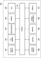
In fig. 2, a zoom unit 201 includes a zoom lens for performing magnification variation (enlargement and reduction of a formed object image). The zoom drive control unit 202 controls the drive of the zoom unit 201, and detects the focal length at this time. The focus unit 203 includes a focus lens for adjusting a focus. The focus drive control unit 204 controls the driving of the focus unit 203. The image pickup unit 206 includes an image sensor. The image pickup unit 206 receives incident light via each lens group, and outputs information of electric charge generated by the amount of light to the image processing unit 207 as an analog image signal. Note that a zoom unit 201, a focus unit 203, and an image pickup unit 206 are arranged inside the lens barrel 102.
The image processing unit 207 applies image processing such as distortion correction, white balance adjustment, color interpolation, and the like to digital image data obtained by a/D converting an analog image signal, and outputs the processed digital image data. The digital image data output from the image processing unit 207 is converted into a format for recording such as JPEG by the image recording unit 208, and then stored in the memory 215, or sent to an image output unit 217 (described later) or the like.
The barrel rotation driving unit 205 rotates the barrel 102 in the pitch direction and the pan direction by driving the pitch rotation unit 104 and the pan rotation unit 105. The device shake detection unit 209 includes an angular velocity meter (gyro sensor) 106 for detecting angular velocities of the camera 101 in the three-axis directions, an accelerometer 107 for detecting accelerations of the camera 101 in the three-axis directions, and the like. The rotation angle, the offset amount, and the like of the device are calculated based on the signals detected by these sensors.
The audio input unit 213 obtains a signal of the ambient audio from the camera 101 via a microphone provided in the camera 101, converts the audio into a digital audio signal, and sends the signal to the audio processing unit 214. The audio processing unit 214 performs audio-related processing such as optimization on the input digital audio signal. The audio signal processed by the audio processing unit 214 is sent to the memory 215 by the first control unit 223. The memory 215 temporarily stores the image signal and the audio signal obtained from the image processing unit 207 and the audio processing unit 214.
The image processing unit 207 and the audio processing unit 214 read out the image signal and the audio signal and the like temporarily stored in the memory 215, and encode the image signal and the audio signal to generate a compressed image signal and a compressed audio signal. The first control unit 223 transmits the compressed image signal and the compressed audio signal to the recording/playback unit 220.
The recording/playback unit 220 records the compressed image signal and the compressed audio signal generated by the image processing unit 207 and the audio processing unit 214, and other control data related to shooting, and the like in the recording medium 221. Without compressing and encoding the audio signal, the first control unit 223 transmits the audio signal generated by the audio processing unit 214 and the compressed image signal generated by the image processing unit 207 to the recording/playback unit 220, and causes these signals to be recorded into the recording medium 221.
The recording medium 221 may be a recording medium built in the camera 101 or a removable recording medium, and is capable of recording various types of data, such as a compressed image signal, a compressed audio signal, and an audio signal generated by the camera 101. For the recording medium 221, a medium having a larger capacity than the nonvolatile memory 216 is generally used. For example, the recording medium 221 may be any type of recording medium, such as a hard disk, an optical disk, a magneto-optical disk, a CD-R, DVD-R, a magnetic tape, a nonvolatile semiconductor memory, or a flash memory.
The recording/playback unit 220 reads out (or plays back) a compressed image signal, a compressed audio signal, an audio signal, various types of data, a program, and the like recorded in the recording medium 221. Then, the first control unit 223 sends the read out compressed image signal and compressed audio signal to the image processing unit 207 and audio processing unit 214. The image processing unit 207 and the audio processing unit 214 temporarily store the compressed image signal and the compressed audio signal in the memory 215, decode these signals by a predetermined process, and send the decoded signals to the image output unit 217.
The audio input unit 213 is provided with a plurality of microphones. The audio processing unit 214 can detect the direction of sound with respect to a plane in which a plurality of microphones are arranged, and thus is used for searching for a subject, automatically capturing an image, and the like, which will be described later. In addition, the audio processing unit 214 detects a specific voice command. This configuration may be as follows: in addition to several commands registered in advance, the user can register a specific voice as a voice command in the camera. The audio processing unit 214 also identifies an audio scene. In audio scene recognition, an audio scene is judged using a network trained in advance by machine learning based on a large amount of audio data. For example, a network for detecting a specific scene such as a viewer's cheering, applause, and speaking is provided in the audio processing unit 214, and the specific audio scene and a specific voice command and the like are detected using the network. Upon detecting a specific audio scene or a specific voice command, the audio processing unit 214 outputs a detection trigger signal to the first control unit 223 or the second control unit 211, or the like.
The camera 101 is provided with a second control unit 211 for controlling power supply of the first control unit 223, in addition to the first control unit 223 for controlling the main system of the camera 101 as a whole. The first power supply unit 210 and the second power supply unit 212 supply power for operation to the first control unit 223 and the second control unit 211, respectively. In response to pressing of a power button provided in the camera 101, power is first supplied to both the first control unit 223 and the second control unit 211. However, as will be described later, the first control unit 223 itself may perform control for cutting off the supply of electric power to the first power supply unit 210. The second control unit 211 operates even when the first control unit 223 is not operating, and takes as input information from the device shake detection unit 209, the audio processing unit 214, and the like. The second control unit 211 determines whether to activate the first control unit 223 based on various input information, and instructs the first power supply unit 210 to supply power to the first control unit 223 when it is determined that the first control unit 223 is to be activated.
The audio output unit 218 outputs a preset audio pattern from a speaker built in the camera 101, for example, during shooting or the like. The LED control unit 224 causes LEDs provided in the camera 101 to light based on a preset lighting pattern, a blinking pattern, or the like, for example, during shooting or the like. The image output unit 217 is constituted by, for example, an image output terminal, and outputs an image signal for causing an image to be displayed in a connected external display or the like. The audio output unit 218 and the image output unit 217 may be a single integrated terminal, such as a High-Definition Multimedia Interface (HDMI (registered trademark) terminal.
The communication unit 222 is a part for performing communication between the camera 101 and an external device, and transmits and receives data such as an audio signal, an image signal, a compressed audio signal, and a compressed image signal, for example. The communication unit 222 also receives commands for starting and stopping shooting, control signals related to shooting such as pan, tilt, and zoom driving, and the like, and drives the camera 101 based on instructions from an external device. The communication unit 222 also transmits and receives information such as various parameters related to learning processed by a learning processing unit 219 (described later) between the camera 101 and an external device. The communication unit 222 includes an infrared communication module, a Bluetooth (registered trademark) communication module, a Wireless LAN communication module, or a Wireless communication module such as a Wireless USB (registered trademark) or a GPS receiver, or the like.
The environment sensor 226 detects the state of the surrounding environment of the camera 101 at predetermined cycles. The environment sensor 226 includes a temperature sensor for detecting the ambient temperature of the camera 101, an atmospheric pressure sensor for detecting a change in atmospheric pressure around the camera 101, and an illuminance sensor for detecting the ambient brightness of the camera 101. The environment sensor 226 also includes a humidity sensor for detecting humidity around the camera 101, a UV sensor for detecting the amount of ultraviolet light around the camera 101, and the like. In addition to the detected temperature information, atmospheric pressure information, luminance information, humidity information, and UV information, in determination of automatic shooting or the like, which will be described later, a temperature change amount, an atmospheric pressure change amount, a luminance change amount, a humidity change amount, an ultraviolet light change amount, and the like calculated as a change rate in a predetermined period of time from the detected various information are used.
Communication with external device
Fig. 3 is a diagram showing an example of the structure of a wireless communication system between the camera 101 and the external device 301. The camera 101 is a digital camera having a photographing function, and the external device 301 is a smart device including a bluetooth communication module and a wireless LAN communication module.
The camera 101 and the external device 301 are capable of communicating via a first communication 302 and a second communication 303 such as bluetooth Low energy (hereinafter referred to as "ble (bluetooth Low energy)") or the like, wherein the first communication 302 uses, for example, a wireless LAN based on the IEEE 802.11 specification series, and the second communication 303 provides a master/slave relationship between the control station and the accessory station. Note that the wireless LAN and BLE are merely examples of the communication method. Other communication methods may be used as long as each communication device has two or more communication functions, one of which for example is capable of controlling the other communication functions for communication within the relationship between the control station and the subsidiary station. However, the following is assumed: the first communication 302 (e.g., wireless LAN) is capable of faster communication than the second communication 303 (e.g., BLE), and the second communication 303 consumes less power, has a shorter communication range, or both than the first communication 302.
The structure of the external device 301 will be described using fig. 4. The external device 301 includes, for example, a wireless LAN control unit 401 and a BLE control unit 402 for BLE for wireless LAN, and a common wireless control unit 406 for common wireless line communication. The external device 301 also includes a packet transmission/reception unit 403. The wireless LAN control unit 401 executes RF control for wireless LAN, communication processing, driver processing for executing various controls for wireless LAN communication based on the IEEE 802.11 specification series, protocol processing relating to communication by wireless LAN, and the like. The BLE control unit 402 performs RF control for BLE, communication processing, driver processing for performing various controls for BLE communication, protocol processing related to communication through BLE, and the like. The common wireless control unit 406 performs RF control for common wireless line communication, communication processing, driver processing for performing various controls for common wireless line communication, protocol processing related to common wireless line communication, and the like. Public wireless line communication is based on standards such as International Multimedia Telecommunications (IMT) or Long Term Evolution (LTE). The packet transmission/reception unit 403 performs processing for performing at least one of transmission and reception of packets relating to wireless LAN, BLE, and public wireless line communication. Although the present embodiment describes the external device 301 as transmitting packets, receiving packets, or both in communication, a communication format other than packet switching, such as circuit switching, may be used instead.
The external device 301 further includes, for example, a control unit 411, a storage unit 404, a GPS receiving unit 405, a display unit 407, an operation unit 408, an audio input/audio processing unit 409, and a power supply unit 410. The control unit 411 controls the entire external device 301 by executing a control program stored in the storage unit 404, for example. The storage unit 404 stores, for example, a control program executed by the control unit 411, and various information such as parameters necessary for communication. Various operations (described later) are realized by the control unit 411 executing a control program stored in the storage unit 404.
The power supply unit 410 supplies power to the external device 301. The display unit 407 has a function of enabling output of visually recognizable information like an LCD, an LED, or the like, or output of audio like a speaker or the like, and displays various types of information. The operation unit 408 includes, for example, a button or the like for accepting an operation of the external device 301 by the user. The display unit 407 and the operation unit 408 may be configured as an integrated member, for example, like a touch panel.
The audio input/audio processing unit 409 is, for example, a general microphone built in the external device 301 for acquiring the voice of the user. The unit may be configured to recognize an operation command from a user through a voice recognition process. Further, using a dedicated application in the external device 301, voice commands issued by the user can be acquired and then registered as specific voice commands to be recognized by the audio processing unit 214 of the camera 101 through the first communication 302 using the wireless LAN.
A GPS (global positioning system) receiving unit 405 estimates the current position (longitude/latitude information) of the external device 301 by receiving GPS signals transmitted from satellites and analyzing the GPS signals. Instead, the current position of the external device 301 may be estimated using a Wi-Fi positioning system (WPS) or the like based on information of wireless networks existing in the surrounding area. The movement information may be communicated to the camera 101 via the BLE control unit 402 in a case where the GPS position information currently acquired is within a preset position range (within a range corresponding to a predetermined radius centered on the detection position), and in a case where the position in the GPS position information has changed by not less than a predetermined amount, or the like. This movement information can be used as a parameter for automatic shooting, automatic editing, and the like to be described later.
As described above, the camera 101 and the external device 301 exchange data by communication using the wireless LAN control unit 401 and the BLE control unit 402. For example, data such as an audio signal, an image signal, a compressed audio signal, and a compressed image signal are transmitted and received. A shooting instruction or the like, voice command registration data, a predetermined position detection notification based on GPS position information, a place movement notification, and the like are also transmitted from the external device 301 to the camera 101. Learning data used by the dedicated application in the external device 301 is also transmitted and received.
Structure of fitting
Fig. 5 is a diagram showing an example of the configuration of an external device 501 capable of communicating with the camera 101. The camera 101 is a digital camera having a photographing function, and the external device 501 is, for example, a wearable device including various sensing units, which can communicate with the camera 101 through a bluetooth communication module.
The external device 501 is configured to be wearable on an arm or the like of a user, for example, and includes a sensor for detecting biological information of the user (such as his or her pulse, heartbeat, blood flow, and the like) at a predetermined cycle, an accelerometer or the like capable of detecting an activity state of the user, and the like.
The biological information detection unit 602 includes, for example, a pulse sensor for detecting a pulse of the user, a heartbeat sensor for detecting a heartbeat of the user, a blood flow sensor for detecting a blood flow of the user, a sensor for detecting a change in potential using a conductive polymer in contact with the skin, and the like. The description given in the present embodiment assumes that a heartbeat sensor is used as the biological information detecting unit 602. The heartbeat sensor detects the heartbeat of the user by, for example, irradiating the skin with infrared light using an LED or the like, detecting infrared light that has passed through living tissue using a light receiving sensor, and executing signal processing. The biological information detection unit 602 outputs the detected biological information as a signal to the control unit 607 (see fig. 6).
The swing detection unit 603 for detecting the activity state of the user includes, for example, an accelerometer or a gyro sensor, and the like, and can detect a motion such as whether the user is moving, or swinging his or her arm, and the like, based on acceleration information. An operation unit 605 for accepting an operation of the external device 501 by a user, and a display unit 604 as an LCD or LED monitor or the like for outputting information in a visually recognizable manner are also provided.
Fig. 6 is a diagram showing the structure of the external device 501. As described above, external device 501 includes, for example, control section 607, communication section 601, biological information detection section 602, swing detection section 603, display section 604, operation section 605, power supply section 606, and storage section 608.
The control unit 607 controls the entire external device 501 by executing a control program stored in the storage unit 608, for example. The storage unit 608 stores, for example, a control program executed by the control unit 607, and various information such as parameters necessary for communication. Various operations (described later) are realized by the control unit 607 executing a control program stored in the storage unit 608, for example.
The power supply unit 606 supplies power to the external device 501. The display unit 604 has an output unit for outputting visually recognizable information such as an LCD or an LED or for outputting audio such as a speaker, and displays various types of information. The operation unit 605 includes, for example, buttons and the like for accepting operations of the external device 501 by the user. The display unit 604 and the operation unit 605 may be configured as an integrated member like a touch panel, for example. The operation unit 605 can acquire the voice of the user using, for example, a general-purpose microphone built in the external device 501. The unit may be configured to recognize an operation command from a user through a voice recognition process.
Various types of detection information acquired by the biological information detection unit 602 and the sway detection unit 603 and then processed by the control unit 607 are transmitted to the camera 101 via the communication unit 601. For example, the detection information may be transmitted to the camera 101 when a change in the heartbeat of the user is detected, or the detection information may be transmitted when there is a change in the movement state of the user such as walking, running, or standing. Further, the detection information may be transmitted when a preset arm swing motion is detected, or the detection information may be transmitted when a movement of a preset distance is detected.
Camera operation sequence
Fig. 7 is a flowchart showing an example of operations performed by the first control unit 223 of the camera 101 according to the present embodiment.
When the user operates a power button provided in the camera 101, power is supplied from the first power supply unit 210 to the first control unit 223 and each block in the camera 101. Similarly, power is supplied from the second power supply unit 212 to the second control unit 211. The operation of the second control unit 211 will be described in detail later using the flowchart of fig. 8.
When power is supplied, the process of fig. 7 starts. In step S701, the startup condition is loaded. In the present embodiment, the following three conditions are provided to start the power supply.
(1) In response to a manual press of the power button, power supply is started.
(2) The power supply is started in response to an activation instruction transmitted from an external device (e.g., the external device 301) through external communication (e.g., BLE communication).
(3) In response to an instruction from the second control unit 211, power supply is started.
Here, in the case where (3) the power supply is started in response to the instruction from the second control unit 211, the start-up condition calculated in the second control unit 211 is loaded. This will be described in detail later using fig. 8. The start-up condition loaded here is used as one parameter element during object search, automatic shooting, and the like, and these will also be described later. Once the startup condition is loaded, the sequence proceeds to step S702.
In step S702, detection signals from various sensors are loaded. One of the sensor signals loaded here is a signal from a sensor for detecting vibration, such as an accelerometer or a gyro sensor in the device shake detection unit 209. There is also a signal indicating the rotational positions of the pitch rotating unit 104 and the yaw rotating unit 105. Further, there are an audio signal detected by the audio processing unit 214, a detection trigger signal for specific voice recognition, a sound direction detection signal, and an environmental information detection signal detected by the environmental sensor 226. Once the detection signals from the various sensors are loaded in step S702, the sequence proceeds to step S703.
In step S703, it is detected whether or not a communication instruction is transmitted from the external apparatus. If the communication instruction is transmitted, communication is performed with the external device. The communication includes, for example: remote operation from the external device 301 through a wireless LAN or BLE; exchange of audio signals, image signals, compressed audio signals, compressed image signals, and the like; an operation instruction for shooting or the like from the external apparatus 301; sending voice command registration data; exchange of predetermined location detection notifications and location movement notifications and learning data based on GPS location information; and so on. The communication further includes: in the case where the biological information (such as activity information, arm movement information, heartbeat, and the like) of the user is updated, the information is loaded from the external device 501 through BLE. Although the environment sensor 226 described above may be provided in the camera 101, the environment sensor 226 may be provided in the external device 301 or the external device 501. In this case, in step S703, the environment information is loaded by BLE. Once information is loaded from the external apparatus by communication in step S703, the sequence proceeds to step S704.
In step S704, a mode setting determination is made, and the sequence thereafter proceeds to step S705. In step S705, it is determined whether the operation mode is set to the low power mode in step S704. If the mode is neither (described later) "automatic shooting mode", "automatic editing mode", "automatic image transfer mode", "learning mode", nor (described later) "automatic file deletion mode", the mode is determined to be a low power mode. If the mode is determined to be the low power mode in step S705, the sequence proceeds to step S706.
In step S706, various parameters (the sway detection determination parameter, the sound detection parameter, and the elapsed time detection parameter) relating to the activation factor determined in the second control unit 211 are communicated to the second control unit 211 (as a sub-CPU). The values of the various parameters are changed by learning in a learning process (described later). Once the processing of step S706 ends, the sequence proceeds to step S707, where in step S707 the first control unit 223 (as the main CPU) is turned off, and the processing ends.
If the mode is determined not to be the low power mode in step S705, it is determined whether the mode setting in step S704 is the automatic photographing mode in step S709. Next, the mode setting determination process performed in step S704 will be described. The mode to be determined is selected from the following modes.
(1) Automatic shooting mode
Mode judging condition
In the case where it is determined that automatic shooting is to be performed based on information such as the following, an automatic shooting mode is set: various types of detection information (images, sounds, time, vibration, places, body changes, environmental changes) set by learning; information indicating an amount of time elapsed since the transition to the automatic shooting mode; and past shooting information and the number of times of shooting of past shooting; and so on.
Processing in this mode
In the automatic shooting mode process (step S710), a subject is automatically searched for by panning, tilting, and zooming operations based on various types of detection information (image, sound, time, vibration, place, body change, and environmental change). Then, when it is determined that photographing matching the preference of the user is possible, photographing is automatically performed.
(2) Automatic edit mode
Mode judging condition
In a case where it is determined that automatic editing is to be performed based on the amount of time elapsed since the last automatic editing and information of images captured in the past, an automatic editing mode is set.
Processing in this mode
In the automatic editing mode processing (step S712), automatic editing processing in which still images, moving images, and the like are selected based on learning processing and collected into a single moving image according to image effects, durations of edited moving images, and the like based on learning is performed to generate a highlight moving image.
(3) Automatic image transfer mode
Mode judging condition
In the case where the automatic image transfer mode is set in response to an instruction made using a dedicated application in the external apparatus 301, the automatic image transfer mode is set when it is determined that automatic transfer should be performed based on the amount of time elapsed since the previous image transfer and information of images captured in the past.
Processing in this mode
In the automatic image transfer mode processing (step S714), the camera 101 automatically extracts an image that is supposed to match the preference of the user, and automatically transfers the image to the external apparatus 301. Extraction of an image matching the preference of the user is performed based on a score determined according to the preference of the user added to each image (described later).
(4) Learning mode
Mode judging condition
The learning mode is set when it is determined that automatic learning should be performed based on the amount of time elapsed since the previous learning process, information integrated with images that can be used in learning, the number of learning data, and the like. When an instruction for setting the learning mode is made by communication from the external apparatus 301, the mode is also set.
Processing in this mode
In the learning mode process (step S716), learning based on the preference of the user is performed using a neural network based on various operation information from the external device 301 (information of an image acquired from the camera, information that has been manually edited via a dedicated application, and determination value information that the user has input for an image within the camera), notification of learning information from the external device 301, and the like. While also performing learning concerning detection (such as registration for personal authentication, voice registration, audio scene registration, and registration for general object recognition), learning of conditions for the above-described low-power mode, and the like.
(5) Automatic file deletion mode
Mode judging condition
The automatic file deletion mode is set in the case where it is determined that automatic file deletion should be performed based on the amount of time elapsed since the last automatic file deletion, the space remaining in the nonvolatile memory 216 for recording images, and the like.
Processing in this mode
In the automatic file deletion mode processing (step S718), a file to be automatically deleted in the nonvolatile memory 216 is specified and deleted based on the tag information of each image and the date/time when the image was captured, and the like.
The processing in each of these modes will be described in detail later.
Returning to fig. 7, if it is determined in step S705 that the mode is not the low power mode, the sequence proceeds to step S709, where in step S709 it is determined whether the mode is set to the auto shooting mode. If the result of the judgment indicates that the mode is the automatic shooting mode, the sequence proceeds to step S710, where in step S710, automatic shooting mode processing is performed. Once the process ends, the sequence returns to step S702, where in step S702 the process is repeated. If the mode is determined not to be the automatic shooting mode in step S709, the sequence proceeds to step S711.
In step S711, it is determined whether the mode is set to the automatic editing mode. If the mode is the automatic edit mode, the sequence proceeds to step S712, where in step S712, automatic edit mode processing is performed. Once the process ends, the sequence returns to step S702, where in step S702 the process is repeated. If the mode is determined not to be the automatic editing mode in step S711, the sequence proceeds to step S713. Since the automatic editing mode has no direct relation to the main subject matter of the present invention, a detailed description of the automatic editing mode will not be given here.
In step S713, it is determined whether the mode is set to the automatic image transfer mode. If the mode is the automatic image transfer mode, the sequence proceeds to step S714, where in step S714, automatic image transfer mode processing is performed. Once the process ends, the sequence returns to step S702, where in step S702 the process is repeated. If the mode is determined not to be the automatic image transfer mode in step S713, the sequence proceeds to step S715. Since the automatic image transfer mode has no direct relation to the main subject of the present invention, a detailed description of the automatic image transfer mode will not be given here.
In step S715, it is determined whether the mode is set to the learning mode. If the mode is the learning mode, the sequence proceeds to step S716, where in step S716, learning mode processing is performed. Once the process ends, the sequence returns to step S702, where in step S702 the process is repeated. If the mode is determined not to be the learning mode in step S715, the sequence proceeds to step S717.
In step S717, it is determined whether the mode is set to the automatic file deletion mode. If the mode is the automatic file deletion mode, the sequence proceeds to step S718, where in step S718, automatic file deletion mode processing is executed. Once the process ends, the sequence returns to step S702, where in step S702 the process is repeated. If it is determined in step S717 that the mode is not the automatic file deletion mode, the sequence returns to step S702, and the process is repeated. Since the automatic file deletion mode has no direct relation to the main subject matter of the present invention, a detailed description of the automatic file deletion mode will not be given here.
Fig. 8 is a flowchart showing an example of operations performed by the second control unit 211 of the camera 101 according to the present embodiment.
When the user operates a power button provided in the camera 101, power is supplied from the first power supply unit 210 to the first control unit 223 and each block in the camera 101. Similarly, power is supplied from the second power supply unit 212 to the second control unit 211.
When the power is supplied, the second control unit (sub CPU)211 starts, and the process shown in fig. 8 starts. In step S801, it is determined whether a predetermined sampling period has elapsed. The predetermined sampling period is set to 10ms, for example, and thus the sequence proceeds to step S802 after the period of 10 ms. In the case where it is determined that the predetermined sampling period has not elapsed, the second control unit 211 stands by.
In step S802, learning information is loaded. The learning information is information transmitted when communicating information to the second control unit 211 in step S706 of fig. 7, and includes the following information, for example.
(1) Judgment of specific shake detection (used in step S804 described later)
(2) Judgment of specific sound detection (used in step S805 described later)
(3) Determination of elapsed time (used in step S807 described later)
Once the learning information is loaded in step S802, the sequence proceeds to step S803, where a shake detection value is acquired in step S803. The shake detection value is a value output by a gyro sensor, an accelerometer, or the like in the device shake detection unit 209.
Once the shake detection value is acquired in step S803, the sequence proceeds to step S804, where in step S804, processing for detecting a preset specific shake state is performed. Here, the determination processing is changed according to the learning information loaded in step S802. Several examples will be given below.
Flick detection
A state (flick state) in which the user taps the camera 101 with his or her fingertip, for example, can be detected from the value output by the accelerometer 107 attached to the camera 101. By passing the output of the triaxial accelerometer 107 through a Band Pass Filter (BPF) set to a specific frequency range at a predetermined sampling period, a signal range corresponding to a change in acceleration caused by a tap can be extracted. Then, a flick is detected based on whether the acceleration signal that has passed the BPF exceeds a predetermined threshold ThreshA a predetermined number of times CountA within a predetermined amount of time TimeA. For a double click, CountA is set to 2, and for a triple click, CountA is set to 3. TimeA and ThreshA may also be changed based on the learning information.
Jitter condition detection
The shake state of the camera 101 can be detected from values output by the gyro sensor 106 and the accelerometer 107 and the like attached to the camera 101. A high-pass filter (HPF) and a low-pass filter (LPF) are used to cut off high-frequency components and low-frequency components of the outputs from the gyro sensor 106 and the accelerometer 107, etc., respectively, and then convert these outputs into absolute values. The vibration is detected based on whether the calculated absolute value exceeds the predetermined threshold ThreshB not less than the predetermined number of times CountB within the predetermined amount of time TimeB. This makes it possible to determine a state in which there is little shake such as a case where the camera 101 is placed on a desk or the like, or a state in which there is much shake such as a case where the camera 101 is attached to the body of the user as a wearable camera and the user is walking. By setting a plurality of conditions for the determination threshold value, the determination count, and the like, the shake state can be detected more finely based on the shake level. TimeB, ThreshB, and CountB may also be changed according to the learning information.
The above describes a method of detecting a specific shake state by judging a detection value from a shake detection sensor. However, by inputting data from the shake detection sensor sampled within a predetermined amount of time into the shake state determiner using the neural network, it is also possible to detect a specific shake state registered in advance using the trained neural network based on the data. In this case, the learning information loaded in step S802 is the weight parameter of the neural network.
Once the specific shake state detection processing is performed in step S804, the sequence proceeds to step S805, where in step S805, processing for detecting a preset specific sound is performed. Here, the detection determination process is changed according to the learning information loaded in step S802. Several examples will be given below.
Specific voice command detection
A specific voice command is detected. In addition to several commands registered in advance, the user can register a specific voice as a voice command in the camera.
Specific audio scene recognition
An audio scene is judged using a network trained in advance by machine learning based on a large amount of audio data. For example, certain scenes such as audience cheering, applause, and speech are detected. The detected scene changes based on learning.
Sound level determination
The sound level is detected by determining whether the volume of the audio level exceeds a predetermined volume within a predetermined amount of time. The predetermined amount of time, the predetermined size, and the like vary based on learning.
Sound direction determination
The direction of sound is detected for sound of a predetermined volume using a plurality of microphones arranged on a plane.
The above-described determination processing is executed within the audio processing unit 214, and it is determined whether or not a specific sound is detected in step S805 based on various settings learned in advance.
When the process for detecting the specific sound is performed in step S805, the sequence proceeds to step S806, where in step S806, it is determined whether the power of the first control unit 223 is turned off. If the first control unit 223 (main CPU) is turned off, the sequence proceeds to step S807, where in step S807, processing for detecting the elapse of the preset amount of time is executed. Here, the detection determination process is changed according to the learning information loaded in step S802. The learning information is information transmitted when communicating information to the second control unit 211 in step S706 of fig. 7. The amount of time elapsed since the first control unit 223 turned on to off is measured. If the amount of elapsed time is greater than or equal to the predetermined amount of time, TimeC, the time is determined to have elapsed, and if the amount of elapsed time is less than TimeC, the time is determined to have not elapsed. TimeC is a parameter that changes according to the learning information.
Once the processing for detecting the amount of elapsed time is executed in step S807, the sequence proceeds to step S808, where it is determined in step S808 whether a condition for canceling the low power mode is satisfied. Whether to cancel the low power mode is determined based on the following conditions.
(1) A particular type of jitter is detected.
(2) A particular sound is detected.
(3) A predetermined amount of time has elapsed.
With regard to (1), it is determined whether or not a specific type of shake is detected by the specific shake state detection processing executed in step S804. With regard to (2), it is determined whether or not the specific sound is detected by the specific sound detection processing executed in step S805. With regard to (3), it is determined whether a predetermined amount of time has elapsed through the process for detecting the amount of elapsed time performed in step S807. If at least one of (1) to (3) is satisfied, it is determined that the low power mode is to be cancelled.
Upon determining in step S808 that the low power mode is to be cancelled, the sequence proceeds to step S809, where in step S809, the power supply of the first control unit 223 is turned on. Then, in step S810, a condition (jitter, sound, or amount of time) for determining that the low power mode is canceled is communicated to the first control unit 223. Then, the sequence returns to step S801, and the process loops. If any condition for canceling the low power mode is not satisfied in step S808 and it is determined that the low power mode will not be canceled, the sequence returns to step S801, and the process loops.
On the other hand, if it is determined in step S806 that the first control unit 223 is on, the sequence proceeds to step S811, where in step S811, the information acquired from steps S803 to S805 is communicated to the first control unit 223. Then, the sequence returns to step S801, and the process loops.
In the present embodiment, the configuration is as follows: even when the first control unit 223 is turned on, the second control unit 211 detects jitter, specific sound, and the like, and communicates the results of these detections to the first control unit 223. However, the configuration may also be as follows: when the first control unit 223 is turned on, the processing of steps S803 to S805 is not performed, and detection of a shake, a specific sound, and the like is performed by the processing within the first control unit 223 (step S702 of fig. 7).
As described above, by the processing in steps S704 to S707 in fig. 7, the processing shown in fig. 8, and the like, the condition for shifting to the low-power mode, the condition for canceling the low-power mode, and the like are learned based on the user operation. This makes it possible to perform a camera operation that matches the way in which the user who owns the camera 101 uses the camera. The method of learning will be described later.
Although the foregoing has described in detail the method for canceling the low-power mode based on the shake detection, the sound detection, or the elapse of time, the low-power mode may be canceled based on the environmental information. The environmental information may be judged based on whether or not the absolute amounts or the variation amounts of the temperature, the atmospheric pressure, the brightness, the humidity, and the ultraviolet light exceed predetermined thresholds, and these thresholds may also be changed based on learning to be described later.
Detection information such as detected shake, sound, and time lapse, and absolute values and amounts of change in each environmental information, and the like may be determined based on the neural network, and may be used to determine whether to cancel the low power mode. The determination condition in this determination process may be changed based on learning which will be described later.
Automatic shooting mode processing
The process performed in the automatic shooting mode will be described using fig. 9A. First, in step S901, the image processing unit 207 performs image processing on a signal obtained from the image capturing unit 206, and generates an image for object detection. Subject detection processing for detecting a person, an object, or the like is performed on the generated image.
In the case of detecting a person, the face, body, and the like of the subject are detected. In the face detection processing, patterns for determining the face of a person are set in advance, and a portion matching these patterns within a captured image can be detected as a face area of the person. While calculating a reliability level indicating a degree of determination that the subject is a face. For example, the reliability level is calculated from the size of a face region within an image, the degree to which the region matches a face pattern, and the like. The same applies to object recognition that recognizes an object matching a pre-registered pattern.
There is also a method of extracting a characteristic object using a histogram of hue, saturation, or the like in a captured image. A distribution calculated from a histogram of hue, saturation, or the like regarding an image of an object found within a shooting angle of view is divided into a plurality of sections, and processing for classifying the captured image in units of sections is performed. For example, a plurality of histograms of color components are created for a captured image, and these histograms are divided into peak-like distribution ranges. The captured images are classified in regions belonging to the same section combination, and an image region corresponding to the subject is identified. Then, by calculating an evaluation value for each image region of the recognized subject, a subject image region having the highest evaluation value can be determined as the main subject region. By the above method, each object information can be obtained from the shooting information.
In step S902, an image blur correction amount is calculated. Specifically, first, the absolute angle of the camera movement is calculated based on the angular velocity and acceleration information obtained by the device shake detection unit 209. Then, an angle at which the image blur is corrected by moving the pitch rotating unit 104 and the pan rotating unit 105 in an angular direction that cancels the absolute angle is found, and this angle is regarded as an image blur correction amount. Note that the calculation method used in the image blur correction amount calculation process performed here may be changed based on a learning process (described later).
In step S903, the state of the camera is determined. The current state of vibration/movement in the camera is determined based on the camera angle and the camera movement amount, etc., detected from the angular velocity information, the acceleration information, the GPS position information, etc. For example, if the camera 101 performs shooting in a state of being mounted on a vehicle, object information such as surrounding scenery will greatly change depending on the distance the vehicle moves. In this manner, it is determined whether or not the camera is in a "vehicle moving state" in which the camera is mounted on a vehicle or the like and is moving at a high speed, and this determination is used in an automatic object search (described later). It is also determined whether the angle of the camera has changed greatly to determine whether the camera 101 is in a "still shooting state" in which the camera hardly experiences wobbling. In this "still shooting state", it can be safely assumed that the camera 101 itself will not change position, and thus object search for still shooting can be performed. On the other hand, when the angle of the camera changes relatively largely, the camera is determined to be in a "hand-held state", and the determination is usable to perform an object search for a hand-held situation.
In step S904, subject search processing is executed. The object search is composed of the following processing.
(1) Region segmentation
(2) Calculating importance levels in units of regions
(3) Determining search object region
These processes will be described in sequence below.
(1) Region segmentation
The region division will be described with reference to fig. 10A to 10E. As shown in fig. 10A, the entire periphery of the camera is divided into regions with the position of the camera serving as the center (the origin O is regarded as the camera position). In the example of fig. 10A, the division is performed for every 22.5 degrees in both the pitch direction and the pan direction. When the division is performed as shown in fig. 10A, as the angle in the pitch direction is away from 0 degrees, the circumference in the horizontal direction becomes small, and these regions also become small. In this way, in the case where the pitch angle is greater than or equal to 45 degrees as shown in fig. 10B, the area range in the horizontal direction is set to be greater than 22.5 degrees.
Fig. 10C and 10D show examples of regions obtained by region division performed within the shooting angle of view. The axis 1301 represents the orientation of the camera 101 in the initial state, and region division is performed using this orientation of the reference position. 1302 denotes a viewing angle region of a captured image, and fig. 10D shows an example of the captured image at this time. Based on the region segmentation performed within the image from the shooting perspective, the image is segmented as shown by reference numerals 1303 to 1318 of fig. 10D.
(2) Calculating importance levels in units of regions
For each of the regions obtained by the above-described division, an importance level indicating a priority order for performing search is calculated from the state of the subject, the state of the scene, and the like in each region. The importance level based on the state of the subject is calculated based on, for example, the number of persons present in the area, the size of the faces of the persons, the orientation of the faces, the degree of determination of face detection, the expressions of the persons, and the personal authentication results of the persons. On the other hand, the importance level based on the state of the scene is calculated based on, for example, a general object recognition result, a scene determination result (blue sky, backlight, night scene, and the like), a level of sound from the direction of the region and a voice recognition result, and motion detection information within the region.
In addition, in the case where vibration is detected in the camera state determination (step S903) in fig. 9A, the importance level may be changed according to the vibration state. For example, if it has been determined as "still shooting state", it is determined that object search is to be performed by focusing attention on an object (e.g., the owner of the camera) with a high priority among objects registered by face authentication. Automatic shooting (described later) is also performed by giving priority to the face of the camera owner, for example. By doing so, even if the owner of the camera typically takes images while the camera is moving around in a state where the camera is attached to his or her body, a larger number of images including the owner can be taken by removing the camera and placing the camera on a table or the like. Since the face can be searched out by panning and tilting at this time, it is possible to simply take an image including the owner, a group photograph including many faces, and the like by placing the camera in an appropriate manner without considering the placement angle of the camera and the like.
Only under the above conditions, if there is no change in the respective regions, the same region will always have the highest level of importance. As a result, the searched area will never change. In view of this, the importance level is changed according to the past shooting information. Specifically, the importance level may be lowered for an area that is continuously specified as a search area for a predetermined amount of time, and the importance level may be lowered for a predetermined amount of time in an area where photographing is performed in step S910 (described later), and so on.
Further, in a case where the camera is moving (such as a case where the camera is attached to the body of the owner of the camera or mounted on a vehicle or the like), there are cases where: when the object search is performed on the surroundings using the pan/tilt function, the object is no longer visible at the point in time when shooting is performed. Alternatively, the subject may have become too far or too small, which makes the subject search meaningless. In view of this, the moving direction and moving speed of the camera, and the like, are calculated from the angular velocity information, acceleration information, and GPS position information detected in step S903, and also from the motion vectors calculated for the respective coordinates in the captured image. Then, based on this, it can be determined from the beginning that there is no object in the region away from the traveling direction. In contrast, the search time interval may be changed according to the moving speed (such as shortening the object search time interval at the time of high-speed movement) in order to ensure that important objects are not missed.
Additional explanation will be given here regarding the zoom position when the importance level is found in units of areas. The importance level is calculated in units of areas in a state where the zoom unit 201 has been driven to the wide-angle side, in a case where a predetermined amount of time has elapsed since the importance level was calculated in units of areas for the first time, and the like. This is because, when the importance degree is calculated for the first time, or when a predetermined amount of time has elapsed since the calculation of the importance degree, it is not known where the important subject is present, and therefore it is necessary to perform the search in a wide range. Finding the importance level at which the zoom unit has been controlled to move to the wide-angle side makes it possible to shorten the time required for the search. After the subject target region is determined, the subject is tracked using zoom driving in step S906 (described later). In a state where the subject is being tracked, the angle of view is controlled by the zoom unit 201 to ensure that the subject has an appropriate size, an appropriate balance with the background, and the like. However, in the case where the subject tracking is to be canceled and the subject is to be searched out again, the importance level is calculated in units of areas after the zoom unit is driven to the wide-angle side.
Note that the pan rotation unit 105 includes a mechanism capable of manual positioning in addition to rotational driving by a motor, and thus the position may also be set manually. The manual panning operation may be detected using a pulse sensor used when the panning rotation unit is driven. When the importance level is calculated in units of areas, if the panning operation is manually performed using the mechanism, the area designated manually is determined to be the most important area. Setting the importance level of the region to an extremely high value makes it possible to determine the search target region in a manner reflecting the user's intention. Further, if a panning operation is manually performed in a state in which an object is being tracked, zooming is quickly controlled to move to the wide-angle side and then the importance level is recalculated in units of area, which makes it possible to determine a search target area in a manner that reflects the user's intention.
At this time, the zoom control amount for moving to the wide-angle side may be changed in accordance with the manual control amount used during the manual panning operation. In other words, upon manually performing a large panning operation, zooming is controlled to move to the wide-angle end, and the importance level for each area is deleted. On the other hand, when a small panning operation is performed, the zooming is controlled to move only slightly toward the wide-angle side, and the importance level for each area is saved at this time. This is useful in improving the possibility that the subject will be correctly captured.
In addition, regarding the pitch drive, when searching for an object, first, a region search is performed from a horizontal position. In particular, when the manual pan operation is performed, the tilt driving is performed so that the camera is horizontal with respect to the ground, and then the object search is performed. Then, after returning to the pitch direction used before the manual panning operation, the object search is performed again. This makes it possible to find an important subject faster.
Fig. 9B is a flowchart showing a zoom control operation performed when the importance level is found in units of areas, which has been generally described so far.
Upon starting the operation for finding the importance level in units of areas, in step S931, it is determined whether or not the subject is currently being tracked. The sequence proceeds to step S934 if the camera is currently tracking the object, and proceeds to step S932 if the camera is not currently tracking the object.
In step S932, it is determined whether this is the first importance level calculation in units of area. If this is the first importance level calculation, the sequence proceeds to step S934, and if this is not the first importance level calculation, the sequence proceeds to step S933.
In step S933, it is determined whether a predetermined amount of time has elapsed since the previous calculation of the importance level in units of area. If the predetermined amount of time has elapsed, the importance level needs to be calculated again, and the sequence therefore proceeds to step S934. However, if the predetermined amount of time has not elapsed, the operation of the flowchart ends with the current zoom position (angle of view) maintained.
In step S934, it is determined whether or not the manual panning operation is performed. If the manual panning operation is performed, the sequence proceeds to step S935, whereas if the manual panning operation is not performed, the sequence proceeds to step S941.
In step S935, it is determined whether the operation amount of the manual panning operation is greater than or equal to a predetermined amount. If the operation amount is greater than or equal to the predetermined amount, the area in the direction in which the user intentionally points the camera is regarded as the most important area. Thus, the sequence advances to step S936, and the zoom is driven to the wide-angle side. At this time, the control amount toward the zoom side is adjusted according to the moving amount of the panning operation confirmed in step S935, which makes it possible to photograph the subject that the user wants to photograph. After this operation is performed, the sequence advances to step S937 to calculate the importance level again in units of regions.
In step S937, the previously stored importance levels are deleted, and then the sequence proceeds to step S938. In step S938, the pitch driving is performed so that the angle of view is horizontal, and in step S939, the importance level is recalculated.
On the other hand, if the manual panning operation is not performed in step S934 or S935, or if the manual panning operation is performed but the operation amount is low, the camera is zoomed out to a predetermined wide angle position slightly before the wide angle end in step S941. Then, in step S942, the stored importance level is held. Alternatively, if this is the first time the importance level is calculated, the importance level is calculated.
In this way, in the case where the importance level is calculated in units of areas, controlling the zoom as described above makes it possible to find an important object more quickly.
(3) Determining search object region
As described above, once the importance level is calculated for each area, an area with a high importance level is determined as a search target area. Then, a pan/tilt search target angle required to photograph the search target area in the angle of view is calculated.
Returning to the explanation of fig. 9A, in step S905, the pan/tilt driving is performed. Specifically, the pan/tilt driving amount is calculated by adding the image blur correction amount to the driving angle based on the pan/tilt search target angle at the control sampling frequency. Then, the driving control of the pitch rotation unit 104 and the panning rotation unit 105 is performed by the barrel rotation driving unit 205.
In step S906, the zoom unit 201 is controlled and zoom driving is performed. Specifically, the zoom is driven according to the state of the object to be searched out determined in step S904. For example, if the subject to be searched out is a face of a person, but the face is too small in the image, the size of the face may be smaller than the minimum size that can be detected. Therefore, the face may not be detected, which results in the face being missed by the camera. In this case, control is performed to zoom to the telephoto side and increase the size of the face in the image. On the other hand, if the face is too large in the image, the subject may move out of the angle of view according to the movement of the subject, the camera itself, and the like. In this case, control is performed to zoom to the wide-angle side and reduce the size of the face in the image. Performing such zoom control makes it possible to maintain a state suitable for tracking the object.
In step S907, it is determined whether or not a shooting instruction is manually made, and if the manual shooting instruction is made, the sequence proceeds to step S910. At this time, a manual shooting instruction can be performed by pressing a shutter button, tapping (tapping) a camera housing with a finger or the like, inputting a voice command, inputting an instruction from an external device, or the like. The shooting instruction that regards the flick operation as a trigger is determined by the device shake detection unit 209 detecting a high-frequency acceleration that continues for a short period of time during which the user flicks the camera housing. The input voice command is a shooting instruction method as follows: in the case where the user speaks a predetermined key phrase (e.g., "take a picture") instructing to take a picture, the audio processing unit 214 recognizes the voice and uses the voice as a trigger for the picture taking. The use of the instruction from the external apparatus is a shooting instruction method as follows: a shutter instruction signal transmitted from a smartphone or the like connected to the camera through bluetooth using a dedicated application is used as a trigger.
If no manual photographing instruction is made in step S907, the sequence proceeds to step S908, where in step S908, automatic photographing determination is performed. In the automatic shooting determination, it is determined whether automatic shooting is performed, and also a shooting method (i.e., it is determined whether a still image, a moving image, a continuous image, a panorama, or the like is shot).
Determining whether to perform automatic photographing
The determination as to whether or not to perform automatic shooting is made in the following manner. Specifically, it is determined that automatic shooting is to be performed in the following two cases. First, based on the importance level of each region obtained in step S904, in the case where the importance level exceeds a predetermined value, it is determined that automatic shooting is to be performed. Second, the determination is made based on a neural network.
Fig. 11 shows a multilayer perceptron network as an example of a neural network. The neural network is used for predicting an output value according to an input value. By learning input values in advance and output values modeling these inputs, output values following the learned model can be estimated for new input values. The method used for this learning will be described later. In fig. 11, 1201 and circles vertically arranged from 1201 denote neurons of an input layer, 1203 and circles vertically arranged from 1203 denote neurons of an intermediate layer, and 1204 denotes neurons of an output layer. Arrows, such as the arrow represented by 1202, represent links connecting neurons. In the neural network-based determination, an object appearing at a current angle of view, a feature amount based on a state of a scene or a camera, and the like are supplied as inputs to neurons of an input layer, and a value output from an output layer is obtained by calculation based on a forward propagation rule of a multilayer perceptron. If the output value is greater than or equal to the threshold value, it is determined that automatic shooting is to be performed. The following features are used as the features of the subject: a current zoom ratio; a general object recognition result and a face detection result at a current view angle; the number of faces, smile intensity of the face, degree of opening/closing of eyes, face angle, face authentication ID number, and line-of-sight angle of a person serving as a subject of the current angle of view; a scene judgment result; the amount of time elapsed since the previous shot; the current time; GPS position information and an amount of change from a previous shooting position; a current audio level; a person making a sound; whether applause or cheering is present; vibration information (acceleration information, camera state); and environmental information (temperature, atmospheric pressure, brightness, humidity, amount of ultraviolet light); and so on. Further, if information is communicated from the external device 501, the information (activity information of the user, motion information of the arm, and biological information such as the heartbeat) is also used as a feature. These features are converted into numerical values within a predetermined range, and the numerical values are supplied as feature quantities to neurons of the input layer. Therefore, it is necessary to set the number of neurons in the input layer to be equivalent to the number of feature quantities used as described above.
In the judgment based on the neural network, the output value may be changed by changing the weight of the connection between neurons in the learning process (described later), and the result of the judgment may be applied to the learning result.
In addition, the judgment of the automatic shooting is also changed according to the start-up condition of the first control unit 223 loaded in step S702 of fig. 7. For example, the possibility that the unit activated in response to the detection of a tap or a specific voice command is an operation indicating that the user currently wishes to capture an image is high. Therefore, the frequency of shooting is set higher.
Shooting method judgment
In the shooting method determination, whether to shoot a still image, a moving image, a continuous image, a panorama, or the like is determined based on the camera state detected in steps S901 to S904, the state of the peripheral object, or the like. For example, in the case where an object (person) is still, a still image is captured, and in the case where the object is moving, a moving image or a continuous image is captured. On the other hand, if a plurality of subjects are surrounding the camera, or it is determined based on the above-described GPS information that the current location is a sight spot or the like, panoramic shooting processing for generating a panoramic image by synthesizing sequentially shot images while panning/tilting the camera may be performed. As with the determination method described in "determining whether to perform automatic shooting", it is also possible to determine various types of information detected before shooting based on a neural network and use the information in shooting method determination. The determination condition in the determination process may be changed based on a learning process to be described later.
Returning to the explanation of fig. 9A, in step S909, if it has been determined in step S908 that automatic shooting is to be performed, the sequence proceeds to step S910, and if it has not been determined that automatic shooting is to be performed, the automatic shooting mode processing ends.
In step S910, automatic shooting is started. At this time, automatic shooting is started using the shooting method determined in step S908. At this time, the focus drive control unit 204 executes autofocus control. In addition, exposure is controlled using a diaphragm control unit, a sensor gain control unit, and a shutter control unit (not shown) so that the subject is at an appropriate brightness. Further, after shooting, the image processing unit 207 performs various types of known image processing such as auto white balance processing, noise reduction processing, and gamma correction processing, and as a result, an image is generated.
During shooting, if a predetermined condition is satisfied, the camera may perform shooting after notifying a person being shot that shooting is being performed. The notification may be performed, for example, by emitting a sound from the audio output unit 218, or blinking an LED using the LED control unit 224, or the like. The predetermined conditions include, for example, the following conditions: the number of faces at the current angle of view, smile intensity of the face, degree of opening/closing of eyes, face angle and line-of-sight angle of a person serving as a subject, face authentication ID number, and the number of persons registered for personal authentication; a general object recognition result at the time of photographing; a scene judgment result; the amount of time elapsed since the previous shot; shooting time; based on the GSP information, whether the current location is a scenic spot; audio level at the time of shooting; whether a person making a sound is present; whether applause or cheering is present; vibration information (acceleration information, camera state); and environmental information (temperature, atmospheric pressure, brightness, humidity, amount of ultraviolet light); and so on. By providing a shooting notification based on these conditions, an image with a better line of sight of the camera can be obtained in a scene with a high degree of importance.
When the notification is provided before shooting in this way, it is also possible to judge information of a shot image or various types of information detected before shooting based on a neural network, and determine a notification method, timing, and the like. The determination condition in this determination process may be changed based on a learning process to be described later.
In step S911, an editing process is performed in which the image generated in step S910 is edited or added to a moving image or the like. The "editing image" specifically includes cropping an image based on the face of a person or the position of a focus, rotating an image, and adding an HDR (high dynamic range) effect, a background blurring effect, a color conversion filter effect, and the like. In the image editing, a plurality of edited images obtained by combining the above-described processes may be generated based on the image generated in step S910, and these edited images may be saved separately from the image generated in step S910. In addition, in processing a moving image, the following processing may be performed: the already shot moving image or still image is added to the already generated edited moving image while adding special effects such as erasing, zooming, and fading in and out. Also in the editing performed in step S911, it is also possible to determine information of a captured image or various types of information detected before capturing based on a neural network, and determine an image editing method. The determination condition in the determination process may be changed based on a learning process to be described later.
In step S912, a captured image learning information generation process is executed. Here, information used in learning processing (described later) is generated and recorded. Specifically, the information is the following information acquired from the currently captured image: a zoom ratio used during shooting; a general object recognition result and a face detection result at the time of photographing; the number of faces in the captured image; smile intensity of the face; degree of opening/closing of the eye; a face angle; a face authentication ID number; an angle of a line of sight of a person serving as a subject; a scene judgment result; the amount of time elapsed since the previous shot; shooting time; GPS position information and an amount of change from the position of the previous shot; audio level at the time of shooting; a person making a sound; whether applause or cheering is present; vibration information (acceleration information, camera state); environmental information (temperature, atmospheric pressure, brightness, humidity, amount of ultraviolet light); a moving image capturing duration; and whether photographing is manually instructed; and so on. A score may also be calculated that is the output of the neural network used to quantify the image preferences of the user. The information is generated and recorded as tag information in the captured image file. Alternatively, the information may be written to the nonvolatile memory 216, or the information of each captured image may be saved in the recording medium 221 in a list format called "directory data".
In step S913, past shooting information is updated. Specifically, the number of images captured at this time is counted up by 1 for the number of times of capturing performed in units of area, the number of times of capturing performed for each person registered for personal authentication, the number of times of capturing performed for each object recognized by general object recognition, and the number of times of capturing performed for each scene from scene determination, which have been described in step S908.
Learning process
Next, learning according to the preference of the user as performed in the present embodiment will be described. In the present embodiment, the learning processing unit 219 employs a machine learning algorithm using a neural network such as the one shown in fig. 11 to perform learning according to the preference of the user. A neural network is a device for predicting an output value from an input value. By learning the actual input value as well as the actual output value, the output value can be estimated for the new input value. Learning according to the preference of the user for the above-described automatic photographing, automatic editing, and object search is performed using a neural network. Operations for changing, by learning, registration of subject information (results of face authentication, general object recognition, and the like), photographing notification control, low-power mode control, automatic file deletion, and the like, which also serve as feature data input to the neural network, are also performed.
In the present embodiment, the learning process is applied to the following operation.
(1) Automatic shooting
(2) Automatic editing
(3) Object search
(4) Subject registration
(5) Shooting notification control
(6) Low power mode control
(7) Automatic file deletion
(8) Image blur correction
(9) Automatic image transfer
In the foregoing operations to which the learning process is applied, automatic editing, automatic file deletion, and automatic image transfer have no direct relationship with the main subject matter of the present invention, and therefore, the three will not be described.
Automatic shooting
Next, learning for automatic shooting will be described. In the automatic shooting, learning is performed so that an image that conforms to the preference of the user is automatically shot. As described using the flowchart of fig. 9A, the learning information generation process (step S912) is executed after the shooting (after step S910). An image to be learned is selected by a method to be described later, and learning is performed by changing the weight of the neural network based on learning information included in the image.
Learning is performed by changing a neural network for determining the automatic shooting timing, and changing a neural network for determining a shooting method (shooting a still image, a moving image, a continuous image, a panoramic image, or the like).
Object search
Next, learning for object search will be described. In the subject search, learning is performed so that subjects that meet the user's preference are automatically searched out. As described using the flowchart of fig. 9A, in the subject search processing (step S904), a subject is searched out by calculating the importance level for each region and then performing pan, tilt, and zoom driving. Learning is performed based on a captured image and currently searched detection information or the like, and is reflected as a learning result by changing the weight of the neural network. An object search reflecting learning is performed by inputting various types of detection information used during a search operation into a neural network and then determining an importance level. In addition to calculating the importance level, for example, controlling the pan/tilt search method (based on the speed or the movement frequency), controlling the object search region according to the movement speed of the camera, and the like are performed.
Subject registration
Next, learning for subject registration will be described. In the subject registration, learning is performed so that subjects that meet the preference of the user are automatically registered and ranked. As the learning, for example, face authentication registration, registration of general object recognition, gesture registration, voice recognition, and scene recognition based on voice, and the like are performed. Authentication registration is performed for a person and an object, and ranking is set based on the number and frequency of times images are acquired, the number and frequency of times manual shooting, and the frequency of occurrence of searched subjects, and the like. The registered information is registered as an input for judgment using each neural network.
Shooting notification control
Next, learning for shooting notification will be described. As described in step S910 of fig. 9A, if a predetermined condition is satisfied immediately before shooting is performed, the camera may perform shooting after notifying a person being shot that shooting is being performed. For example, the line of sight of the subject is visually guided by pan/tilt driving, the attention of the subject is drawn using a speaker sound emitted from the audio output unit 218, and blinking an LED lamp using the LED control unit 224, or the like. Whether or not to use the detection information for learning is determined immediately after the above notification based on whether or not the detection information (for example, smile intensity, line-of-sight detection, gesture, and the like) of the subject is obtained, and then learning is performed by changing the weight of the neural network.
Detection information immediately before shooting is input to the neural network, and it is determined whether or not to perform notification, various operations to be performed (sound level/sound type/timing), light (lighting time, speed), orientation of the camera (pan/tilt movement)), and the like.
Low power mode control
As described using fig. 7 and 8, the power supply to the main CPU (first control unit 223) is controlled to be on and off, but learning is also performed for the condition for returning from the low-power mode, the condition for shifting to the low-power mode, and the like. The learning of the condition for canceling the low power mode will be described next.
Flick detection
As described above, the predetermined amount of time TimeA and the predetermined threshold thresh, etc. are changed by learning. In the state where the above-described tap detection threshold has been lowered, preliminary tap detection is also performed, and the parameters of TimeA, ThreshA, and the like are set to be more easily detected based on whether or not it is determined as preliminary tap detection before tap detection. If it is determined from the camera detection information after the tap detection that the tap is not the cause of the startup, the parameters of TimeA and ThreshA, etc. are set to make the tap detection more difficult.
Jitter condition detection
As described above, the predetermined amount of time TimeB, the predetermined threshold ThreshB, the predetermined number of times CountB, and the like are changed by learning. If the result of judging the jitter state meets the starting condition, starting is executed; however, if it is determined from the camera detection information obtained in a predetermined amount of time after the startup that these results are not the cause of the startup, learning is performed to make the startup based on the judgments of the shake state more difficult. In addition, if it is determined that shooting is frequently performed in a state where the shake amount is extremely large, setting is made so that startup based on shake state determination is more difficult.
Sound detection
For example, the learning may be performed by the user manually setting a specific voice, a specific audio scene to be detected, a specific sound level, or the like via communication using a dedicated application in the external device 301. The learning may also be performed by setting a plurality of detection methods in advance in the audio processing unit, selecting an image to be learned by a method to be described later, learning front-rear sound information included in the image, and then setting sound judgment (a specific sound command, or an audio scene such as cheering or applause, or the like) to be used as a cause of the startup.
Environmental information detection
For example, the learning may be performed by the user manually setting a change of the environmental information to be used as the start-up condition via communication using a dedicated application in the external device 301. For example, the activation may be caused under specific conditions of temperature, atmospheric pressure, brightness, humidity, and absolute amount or variation amount of ultraviolet light amount, or the like. The determination threshold based on each environmental information may also be learned. If it is determined from the camera detection information after the startup using the environment information that the information is not the cause of the startup, the parameters of the respective determination thresholds are set so that it is more difficult to detect the environmental change.
The above parameters are also changed according to the remaining capacity of the battery. For example, when the remaining amount of the battery is small, various determinations are made more difficult, and when the remaining amount of the battery is large, the determination is made easier. Specifically, there are the following cases: even when the shake state detection result, the sound scene detection result, or the like does not absolutely indicate that the user wishes to activate the camera, it is determined that the camera is activated when the remaining capacity of the battery is large.
In addition, the determination of the condition for canceling the low power mode may be made based on a neural network using shake detection, sound detection, information of detection of an elapsed amount of time, various types of environmental information, and a remaining capacity of a battery, or the like. In this case, an image to be learned is selected by a method to be described later, and learning is performed by changing the weight of the neural network based on learning information included in the image.
Next, the learning of the condition for shifting to the low-power mode will be described. As shown in fig. 7, when it is determined in the mode setting determination of step S704 that the mode is neither the "auto shooting mode", the "auto editing mode", the "auto image transfer mode", the "learning mode", or the "auto file deletion mode", the mode is shifted to the low power mode. The conditions for determining the respective modes are as described above, but the conditions for determining the respective modes are also changed by learning.
Automatic shooting mode
As described above, automatic shooting is performed by determining the importance level in units of areas and then controlling panning/tilting while searching out an object, but if it is determined that there is no object to be shot, the automatic shooting mode is cancelled. For example, in a case where the importance levels of all the regions, or the value obtained by adding together the importance levels of the regions has fallen below a predetermined threshold value, the automatic shooting mode is cancelled. At this time, the predetermined threshold may also be decreased according to the amount of time elapsed from the transition to the automatic shooting mode. The transition to the low power mode is made easier as the amount of time elapsed since the transition to the auto shooting mode increases.
In addition, the low power mode may be controlled according to the remaining capacity of the battery by changing the predetermined threshold according to the remaining capacity of the battery. For example, when the remaining amount of the battery is small, the threshold is increased to make it easier to shift to the low-power mode, and when the remaining amount of the battery is large, the threshold is decreased to make it more difficult to shift to the low-power mode. Here, a parameter (threshold TimeC of the amount of elapsed time) for the condition for canceling the low power mode next time is set for the second control unit 211 (sub CPU) according to the amount of elapsed time from the previous transition to the automatic shooting mode and the number of times of shooting performed. The above threshold value is changed by learning. For example, the learning is performed by manually setting a shooting frequency and a start-up frequency, and the like, via communication using a dedicated application in the external device 301.
On the other hand, the configuration may be as follows: the distribution data is accumulated for an average value or a time period of elapsed time from when the power button of the camera 101 is turned on until when the power button is turned off, and these parameters are learned. In this case, learning is performed so that the time for recovering from and transitioning to the low-power mode or the like becomes short for a user who keeps the power supply on only for a short time and becomes long for a user who keeps the power supply on for a long time.
Learning is also performed using the detection information during the search. Learning is performed such that the time for recovery from the low-power mode and transition to the low-power mode or the like becomes shorter if it is determined that there are a plurality of subjects set to be important by learning, and becomes longer if it is determined that there are no plurality of such important subjects.
Image blur correction
Next, learning for image blur correction will be described. The image blur correction is performed by calculating a correction amount in step S902 of fig. 9A, and then performing pan/tilt driving in step S905 based on the correction amount. In the image blur correction, learning is performed so that the correction matches the feature of the shake of the user. For example, the direction and magnitude of blur can be estimated in a captured image by using a Point Spread Function (PSF). In the learning information generation performed in step S912 of fig. 9A, the direction and magnitude of the estimated blur are added as information to the image.
In the learning mode process executed in step S716 of fig. 7, the weight of the neural network used for image blur correction is learned by using the estimated direction and magnitude of blur as outputs and using various types of detection information acquired during shooting (motion vector information of an image within a predetermined amount of time before shooting, movement information of a detected subject (person or object), vibration information (gyro sensor output, acceleration output, camera state)) as inputs. The determination may also be performed by adding other information as input, such as: environmental information (temperature, atmospheric pressure, brightness, humidity), sound information (audio scene determination, specific audio detection, sound level change), time information (amount of time elapsed since startup, amount of time elapsed since previous shooting), and location information (GPS position information, amount of change in position movement), and the like.
When the image blur correction amount is calculated in step S902, the above-described detection information is input to the neural network, which makes it possible to estimate the magnitude of blur in the image captured at that instant. When the magnitude of the estimated blur is high, control for increasing the shutter speed or the like may also be performed. When the estimated blur size is high, the resulting image will be blurred, and thus a method of prohibiting photographing may also be used.
Since there is a limit to the pan/tilt drive angle, once the end of the drive range is reached, no further correction can be performed. However, estimating the magnitude and direction of blur at the time of shooting makes it possible to estimate the pan/tilt driving range necessary to correct image blur during exposure. If there is no margin in the movement range during exposure, it is possible to suppress a large blur by increasing the cutoff frequency of the filter used in calculating the image blur correction amount so as not to exceed the movement range. Further, when it appears that the movement range will be exceeded, the exposure is started after the pan/tilt angle is first rotated in the direction opposite to the direction in which it appears that the movement range will be exceeded immediately before the exposure, which makes it possible to remain within the movement range and take an image without blur. This makes it possible to learn image blur correction that matches the features of the user when taking an image, the way the user uses the camera, and the like, and this in turn makes it possible to prevent the taken image from being blurred.
In the "shooting method determination" described above, it may be determined whether or not "panning" in which the moving subject is sharp but the stationary background is undergoing motion blur is performed. In this case, the pan/tilt driving speed for photographing an object without blur may be estimated from the detection information until photographing, and then the object blur correction may be performed. At this time, the above-described detection information is input to the trained neural network, which makes it possible to estimate the driving speed. The image is divided into blocks, and the PSF is estimated for each block to estimate the direction and magnitude of blur in the block in which the main object is located, and learning is performed based on this information.
The background blur amount may also be learned from information of an image selected by the user. In this case, the size of blur in a block in which the main subject is not located is estimated, and the preference of the user can be learned based on this information. By setting the shutter speed used during shooting based on the learned background blur amount of the preference, shooting with a panning effect matching the preference of the user can be automatically performed.
Next, the learning method will be explained. As the learning method, "learning in a camera" and "learning by linking to a communication apparatus" can be given.
A method of learning in the camera will be described below. The learning in the camera according to the present embodiment includes the following method.
(1) Learning from detection information obtained during manual shooting
(2) Learning from detection information obtained during object search
Learning from detection information obtained during manual shooting
As described with reference to steps S907 to S913 of fig. 9A, in the present embodiment, the camera 101 can perform shooting by both manual shooting and automatic shooting. If a manual shooting instruction is made in step S907, information indicating that the shot image is a manually shot image is added in step S912. However, if it is determined in step S909 that an image is captured with the automatic capturing turned on, information indicating that the captured image is an automatically captured image is added in step S912.
Here, if an image is manually captured, there is a high possibility that an image is captured based on a preference subject, a preference scene, a preference place, a time interval, and the like of the user. Therefore, learning is performed based on feature data obtained during manual shooting, learning information of a shot image, and the like. In addition, learning related to extraction of feature amounts from a captured image, personal authentication registration, registration of expressions in units of individuals, registration of a combination of persons, and the like is performed based on detection information obtained during manual capturing. Learning is also performed to change the importance level of a nearby person or object based on detection information (e.g., the expression of a subject registered as a person) obtained during subject search.
Learning from detection information obtained during object search
During a subject search operation, the types of persons, objects, and scenes that appear simultaneously with a subject registered for personal authentication are determined, and the time ratio at which these objects appear simultaneously in the same angle of view is calculated. For example, a time ratio is calculated at which a person a as an object registered for personal authentication and a person B as an object also registered for personal authentication appear simultaneously. In the case where the person a and the person B are within the same angle of view, each type of detection information is saved as learning data so that the score for automatic shooting determination is increased, and then learning is performed by the learning mode processing (step S716).
As another example, a time ratio at which the person a as an object registered for personal authentication and the object "cat" determined by the general object recognition appear simultaneously is calculated. In the case where the person a and the cat are within the same angle of view, each type of detection information is saved as learning data so that the score for the automatic shooting determination is increased, and then learning is performed by the learning mode processing (step S716).
Further, in the case where a very large smile or an expression indicating happiness or surprise or the like is detected in the person a as a subject registered for personal authentication, learning is performed so that subjects appearing at the same time are regarded as important. Alternatively, for example, if an expression indicating anger, seriousness, or the like is detected, a subject appearing at the same time is less likely to be important, and processing is performed so that learning is not performed.
Next, learning by linking to an external device according to the present embodiment will be explained. The learning by linking to the external device according to the present embodiment includes the following method.
(1) Learning from images acquired by external devices
(2) Learning by inputting a determination value for an image via an external device
(3) Learning by analyzing images held in an external device
(4) Learning based on information uploaded to an SNS server by an external device
(5) Learning by changing camera parameters using external devices
(6) Learning from information of images manually edited using external device
Learning from images acquired by external devices
As described with reference to fig. 3, the camera 101 and the external device 301 have communication units for performing the first communication 302 and the second communication 303. The image is transmitted and received mainly by the first communication 302, and the image within the camera 101 can be transmitted to the external apparatus 301 using a dedicated application set in the external apparatus 301. In addition, a thumbnail image of image data saved in the camera 101 can be browsed using a dedicated application provided in the external device 301. The user can transmit the image to the external device 301 by selecting the image he or she likes from the thumbnail images, confirming the image, and instructing to acquire the image.
At this time, since the image is acquired based on the selection of the user, the possibility that the acquired image is an image that the user likes is high. In this manner, it is determined that the acquired image is an image that should be learned, and various types of learning for the preference of the user can be performed by performing learning based on the learning information of the acquired image.
Examples of these operations will be described herein. Fig. 12 shows an example of browsing an image in the camera 101 using a dedicated application provided in the external device 301. Thumbnail images (1604 to 1609) of image data saved in the camera are displayed in the display unit 407, and the user can select and acquire an image he or she likes. At this time, buttons 1601, 1602, and 1603 constituting a display method changing unit for changing the display method are provided.
Pressing the button 1601 shifts to a date/time priority display mode in which images in the camera 101 are displayed in the display unit 407 in accordance with the date/time at which the images were captured. For example, an image whose date/time is latest is displayed at a position indicated by 1604, and an image whose date/time is earliest is displayed at a position indicated by 1609.
Pressing the button 1602 shifts to a recommended image priority display mode. Based on the scores calculated in step S912 of fig. 9A for determining the preference of the user for each image, the images within the camera 101 are displayed in the display unit 407 in order from the image with the highest score. For example, the image with the highest score is displayed at the position indicated by 1604, and the image with the lowest score is displayed at the position indicated by 1609.
By pressing a button 1603, a subject such as a person or an inanimate object can be specified, and a specific person or object is specified so that only an image with the specific subject can be displayed. Buttons 1601-1603 can also be set to be turned on at the same time. For example, if all of these buttons are set to on, only an image containing a specified object is displayed in a state where an image newly captured and having a higher score is preferentially displayed. In this way, learning is also performed in accordance with the user's preference for captured images, which makes it possible to extract only images matching the user's preference from among a large number of captured images using a simple confirmation operation.
Learning by inputting a determination value for an image via an external device
As described above, the camera 101 and the external device 301 include a communication unit, and images saved in the camera 101 can be browsed using a dedicated application provided in the external device 301. Here, the configuration may add a score to each image for the user. The user may add a high score (e.g., 5 scores) to an image he or she likes and a low score (e.g., 1 score) to an image he or she does not like, and the configuration is learned by the camera based on the user operation. The scores of the images are used in the camera for relearning along with the learning information. Learning is performed so that the output of the neural network having the feature data from the specified image information as an input approaches the score specified by the user.
In the present embodiment, the configuration is such that the user uses the external device 301 to input a determination value for a captured image. However, this configuration may be such that the user operates the camera 101 to directly input the determination value for the image. In this case, the camera 101 is provided with, for example, a touch panel display, and the user presses a GUI button displayed in a screen display portion of the touch panel display to shift to a mode for displaying a captured image. Then, the same type of learning is performed using a method such as a user inputting a determination value for each image that has been captured while confirming the image.
Learning by analyzing images held in an external device
The external device 301 includes a storage unit 404, and it is assumed that the configuration records images other than the image captured by the camera 101 in the storage unit 404. At this time, the image saved in the external device 301 can be easily viewed by the user, and can also be easily uploaded to the shared server via the common wireless control unit 406. Therefore, there is a high possibility that many images matching the preference of the user exist.
The control unit 411 of the external device 301 is configured to be able to process the image held in the storage unit 404 using a dedicated application at the same performance level as the learning processing unit 219 in the camera 101. Then, learning is performed by communicating the processed learning data to the camera 101. Alternatively, the configuration may be as follows: images, data, and the like to be learned are transmitted to the camera 101, and then are learned within the camera 101. The following configuration is also possible: the user selects images to be learned from among the images saved in the storage unit 404 using a dedicated application, and then learns the images.
Learning based on information uploaded to an SNS server by an external device
A method of using information from a Social Network Service (SNS), which is a service or a website or the like that constructs a social network service whose main object is to connect people with each other, for learning will now be described. The following techniques exist: in uploading an image to the SNS, tags related to the image are input from the external device 301 and then transmitted together with the image. There are also techniques as follows: the user inputs whether he or she likes or dislikes the images uploaded by the other users, and thus it is possible to determine whether the images uploaded by the other users are images matching the preferences of the owner of the external device 301.
As described above, the image uploaded by the user himself or herself and the information related to the image may be acquired using the dedicated SNS application downloaded to the external device 301. It is also possible to acquire images and tag information, etc. matching the user's preferences by inputting whether the user likes images uploaded by other users. This makes it possible to perform learning within the camera 101 by analyzing these images and tag information and the like.
The control unit 411 of the external device 301 is configured to be able to acquire images uploaded by the user, images determined to be liked by the user, and the like as described above, and execute processing with the same performance as the learning processing unit 219 in the camera 101. Then, learning is performed by communicating the processed learning data to the camera 101. Alternatively, the configuration may be as follows: images to be learned are sent to the camera 101 and then learned within the camera 101.
Information of a subject that is likely to match the preference of the user can be estimated from subject information (e.g., object information indicating the type of the subject such as a dog or cat, scene information indicating a beach, and expression information indicating smiling, and the like) set in the tag information. Then, learning is performed by registering the subject as a subject to be detected to be input to the neural network.
The following configuration is also possible: information of an image that is popular in the current world is estimated from the statistical values of the above-described SNS tag information (image filter information, object information, and the like), and then can be learned in the camera 101.
Learning by changing camera parameters using external devices
As described above, the camera 101 and the external device 301 include the communication unit. The learning parameters (neural network weights, selection of an object input to the neural network, and the like) currently set in the camera 101 may be communicated to the external device 301 and saved in the storage unit 404 of the external device 301. In addition, it is possible to acquire learning parameters set in the dedicated server via the common wireless control unit 406 using a dedicated application set in the external device 301 and set these learning parameters as learning parameters within the camera 101. Thus, by setting parameters from a certain point in time in the external device 301 and setting these parameters in the camera 101, the learning parameters can be restored. In addition, it is possible to acquire learning parameters held by other users via a dedicated server and set the learning parameters in the user's own camera 101.
In addition, voice commands, authentication registration, and gestures registered by the user can be registered using a dedicated application provided in the external device 301, and also important places can be registered. This information is handled as a shooting trigger during the auto shooting mode processing (fig. 9A), input data for auto shooting determination, and the like. In addition, with a configuration such that the shooting frequency, the start-up interval, the ratio of still images to moving images, and the preference image and the like can be set, the start-up interval and the like described above in the "low power mode control" can be set.
Learning from information of images manually edited using external device
The dedicated application in the external device 301 may be provided with a function of allowing the user to manually edit an image, and details of the editing operation may be fed back into the learning process. For example, editing to add image effects (cropping, rotation, erasing, scaling, fading, color conversion filter effects, time, still image/moving image scale, BGM, and the like) may be performed. Then, a neural network used for automatic editing is trained using learning information from the image so that it is determined that the image effect that has been manually edited is added.
Next, the learning processing sequence will be explained. In the mode setting judgment performed in step S704 of fig. 7, it is judged whether or not the learning process should be performed. If it is determined that the learning process should be performed, the learning mode process of step S716 is performed.
First, the learning mode determination condition will be explained. Whether to transit to the learning mode is determined based on the amount of time elapsed since the previous learning process, the amount of information that can be used in learning, and whether there is an instruction to execute the learning process made via the communication device, or the like. A flow of processing for determining whether to shift to the learning mode, which is executed within the mode setting determination processing of step S704, is shown in fig. 13.
When the start of the learning mode determination is instructed in the mode setting determination process of step S704, the process shown in fig. 13 starts. In step S1401, it is determined whether or not there is a registration instruction from the external apparatus 301. Here, "registration" refers to determination as to whether or not there is a registration instruction for learning such as the following: the above-described "learning from an image acquired by an external apparatus", "learning by inputting a determination value for an image via an external apparatus", and "learning by analyzing an image held in an external apparatus".
If there is a registration instruction from the external device 301 in step S1401, the sequence proceeds to step S1408, where in step S1408 the learning mode determination is set to "true", so that the processing of step S716 is performed. Then, the learning mode determination processing ends. However, if there is no registration instruction from the external apparatus in step S1401, the sequence proceeds to step S1402.
In step S1402, it is determined whether or not there is a learning instruction from the external apparatus. Here, the "learning instruction" refers to a determination as to whether or not there is an instruction to set the learning parameter, like "learning by changing the camera parameter using an external device". If there is a learning instruction from the external apparatus in step S1402, the sequence proceeds to step S1408, where in step S1408, the learning mode is determined to be "true", so that the process of step S716 is performed. Then, the learning mode determination processing ends. However, if there is no learning instruction from the external apparatus in step S1402, the sequence proceeds to step S1403.
In step S1403, the amount of time, TimeN, that has elapsed since the previous learning process (recalculation of neural network weights) was performed is acquired, after which the sequence proceeds to step S1404. In step S1404, the number DN of data to be newly learned (the number of images designated for learning during the amount of time TimeN elapsed since the previous learning process was performed) is acquired, after which the sequence proceeds to step S1405. In step S1405, a threshold DT for determining whether to enter the learning mode based on the elapsed amount of time TimeN is calculated. The setting is as follows: the lower the value of the threshold DT, the easier it is to enter the learning mode. For example, DTa, which is the value of the threshold DT when the TimeN is smaller than a predetermined value, is set higher than DTb, which is the value of the threshold DT when the TimeN is larger than a predetermined value, and the threshold is set to decrease as time passes. Therefore, even if the learning data is small, the learning mode is more easily entered when a larger amount of time has elapsed. Performing learning again makes it easier for the camera to change by learning according to the amount of time the camera is used.
Once the threshold DT is calculated in step S1405, the sequence proceeds to step S1406, where in step S1406, it is determined whether the number of data DN used for learning is greater than the threshold DT. If the number of data DN is greater than the threshold DT, the sequence proceeds to step S1407, where DN is set to 0 in step S1407. Then, the sequence proceeds to step S1408, where in step S1408, the learning mode determination is set to "true", so that the process of step S716 (fig. 7) is performed. Then, the learning mode determination processing ends.
If DN is less than or equal to the threshold DT in step S1406, the sequence proceeds to step S1409. Here, there are no registration instruction and learning instruction from the external apparatus, and the number of data used for learning is less than or equal to a predetermined value. Therefore, the learning mode determination is set to "false" so that the processing of step S716 is not performed, after which the learning mode determination processing ends.
Next, the process executed in the learning mode process (step S716) will be described. Fig. 14 is a detailed flowchart showing an operation performed in the learning mode process.
When it is determined in step S715 of fig. 7 that the mode is the learning mode and the sequence proceeds to step S716, the process shown in fig. 14 starts. In step S1501, it is determined whether or not there is a registration instruction from the external apparatus 301. If there is a registration instruction from the external device 301 in step S1501, the sequence proceeds to step S1502. In step S1502, various registration processes are executed.
The various types of registration are registration of features to be input to the neural network, such as registration of face authentication, registration of general object recognition, registration of sound information, registration of place information, and the like. Once the registration process ends, the sequence proceeds to step S1503, where in step S1503, the elements input to the neural network are changed based on the information registered in step S1502. Once the process of step S1503 ends, the sequence advances to step S1507.
If it is determined in step S1501 that there is no registration instruction from the external apparatus 301, the sequence proceeds to step S1504, where in step S1504, it is determined whether there is a learning instruction from the external apparatus 301. If there is a learning instruction from the external device 301, the sequence proceeds to step S1505, where in step S1505, the learning parameters communicated from the external device 301 are set in various judgers (i.e., neural network weights, etc.). Then, the sequence advances to step S1507.
However, if there is no learning instruction from the external device 301 in step S1504, learning (recalculation of weights of the neural network) is performed in step S1506. In the case where the number DN of data to be learned exceeds the threshold DT and the respective judgers are to be relearned as described using fig. 13, the process of step S1506 is performed. Relearning is performed using methods such as error back-propagation or gradient descent, recalculating weights in the neural network, and changing the parameters of the judgers. Once the learning parameters are set, the sequence proceeds to step S1507.
In step S1507, the images in the file are rescored. In the present embodiment, all the captured images saved in the file (recording medium 221) are given scores based on the learning result, and the configuration is such that automatic editing, automatic file deletion, and the like are performed in accordance with the provided scores. Therefore, when the learning parameters are set via relearning or from an external device, it is also necessary to update the score given to the captured image. Thus, in step S1507, recalculation is performed to give a new score to the captured image saved in the file, and when the processing ends, the learning mode processing also ends.
The present embodiment describes a configuration in which learning is performed in the camera 101. However, the same learning effect can be achieved even with a structure in which the external device 301 is provided with a learning function, data necessary for learning is communicated to the external device 301, and learning is performed only in the external device. In this case, the configuration may be as follows: as described above in "learning to change camera parameters by using an external device", learning is performed by setting parameters such as neural network weights or the like learned in the external device in the camera 101 using communication.
Alternatively, the configuration may be as follows: a learning function is provided in both the camera 101 and the external device 301, in which learning information held by the external device 301 is communicated to the camera 101 when, for example, a learning mode process is to be executed in the camera 101 (step S716), and then learning is executed by incorporating learning parameters.
OTHER EMBODIMENTS
The embodiments of the present invention can also be realized by a method in which software (programs) that execute the functions of the above-described embodiments is supplied to a system or an apparatus via a network or various storage media, and a computer or a Central Processing Unit (CPU), a Micro Processing Unit (MPU) of the system or the apparatus reads out and executes a method of the programs.
While the present invention has been described with reference to exemplary embodiments, it is to be understood that the invention is not limited to the disclosed exemplary embodiments. The scope of the following claims is to be accorded the broadest interpretation so as to encompass all such modifications and equivalent structures and functions.
Claims (10)
1. An image pickup apparatus includes:
an image pickup means for picking up an object image;
a detection means for detecting a state of an object in image data captured by the image capturing means;
a calculation means for dividing a shooting angle of view of the image pickup means into a plurality of regions and calculating an importance level of each region according to a state of an object existing in each of the plurality of regions; and
control means for controlling the calculation means to delete the previously stored importance level and recalculate the importance level of each of the plurality of regions after changing the photographing angle of view to the wide-angle side in a case where an operation amount in a case where the manual pan operation is performed on the image pickup means is greater than or equal to a predetermined amount.
2. The image pickup apparatus according to claim 1,
wherein the control means determines an area of which the importance level is high as an area to search for the subject based on the importance levels of the plurality of areas.
3. The image pickup apparatus according to claim 1,
wherein, in a case where the calculation of the importance level by the calculation means is the first calculation or in a case where a predetermined amount of time has elapsed after the previous calculation of the importance level, the control means performs control such that the photographing angle of view is changed to the wide-angle side regardless of the operation amount in a case where the manual panning operation is performed on the image pickup means.
4. The image pickup apparatus according to claim 1,
wherein the control means executes control such that the photographing angle of view is changed to a wide-angle side in a case where a manual panning operation is performed on the image pickup means.
5. The image pickup apparatus according to claim 4,
wherein the control means controls an amount by which the photographing angle of view is changed to a wide-angle side, based on an operation amount in a case where the manual panning operation is performed on the image pickup means.
6. The image pickup apparatus according to claim 5,
wherein the control means performs control such that the photographing angle of view is changed to a predetermined wide-angle position before a wide-angle end in a case where an operation amount in a case where the manual pan operation is performed on the image pickup means is smaller than a predetermined amount.
7. The image pickup apparatus according to claim 6,
wherein the control means holds the previously stored importance level in a case where an operation amount in a case where the manual pan operation is performed on the image pickup means is smaller than a predetermined amount.
8. The image pickup apparatus according to claim 4,
wherein the control means moves the image pickup means to a horizontal position with respect to a pitch direction when the manual pan operation is performed on the image pickup means.
9. A control method of an image capturing apparatus including image capturing means for capturing an object image, comprising:
detecting a state of an object in image data captured by the imaging means;
dividing a photographing angle of view of the image pickup means into a plurality of regions, and calculating an importance level of each region according to a state of an object existing in each of the plurality of regions; and
the calculation is controlled so that, in a case where an operation amount in a case where a manual pan operation is performed on the image pickup section is greater than or equal to a predetermined amount, after the photographing angle of view is changed to the wide-angle side, the previously stored importance level is deleted, and the importance level of each of the plurality of regions is recalculated.
10. A computer-readable storage medium storing a program for causing a computer to execute the steps of a control method of an image capturing apparatus including image capturing means for capturing an object image, the control method comprising:
detecting a state of an object in image data captured by the imaging means;
dividing a shooting angle of view of the image pickup means into a plurality of regions, and calculating an importance level of each region according to a state of an object existing in each of the plurality of regions; and
the calculation is controlled so that, in a case where an operation amount in a case where a manual pan operation is performed on the image pickup section is greater than or equal to a predetermined amount, after the photographing angle of view is changed to the wide-angle side, the previously stored importance level is deleted, and the importance level of each of the plurality of regions is recalculated.
Applications Claiming Priority (2)
| Application Number | Priority Date | Filing Date | Title |
|---|---|---|---|
| JP2018229210A JP7222683B2 (en) | 2018-12-06 | 2018-12-06 | IMAGING DEVICE AND CONTROL METHOD THEREOF, PROGRAM, STORAGE MEDIUM |
| JP2018-229210 | 2018-12-06 |
Publications (2)
| Publication Number | Publication Date |
|---|---|
| CN111294488A CN111294488A (en) | 2020-06-16 |
| CN111294488B true CN111294488B (en) | 2022-08-12 |
Family
ID=70971373
Family Applications (1)
| Application Number | Title | Priority Date | Filing Date |
|---|---|---|---|
| CN201911241530.4A Active CN111294488B (en) | 2018-12-06 | 2019-12-06 | Image pickup apparatus, control method thereof, and storage medium |
Country Status (3)
| Country | Link |
|---|---|
| US (1) | US11184550B2 (en) |
| JP (1) | JP7222683B2 (en) |
| CN (1) | CN111294488B (en) |
Families Citing this family (8)
| Publication number | Priority date | Publication date | Assignee | Title |
|---|---|---|---|---|
| JP7348754B2 (en) * | 2019-06-03 | 2023-09-21 | キヤノン株式会社 | Image processing device and its control method, program, storage medium |
| JP2022053356A (en) | 2020-09-24 | 2022-04-05 | キヤノン株式会社 | Communication device, control method thereof, and program |
| US11659268B2 (en) | 2020-09-24 | 2023-05-23 | Canon Kabushiki Kaisha | Imaging apparatus capable of automatically capturing image, control method, and recording medium |
| US11893668B2 (en) | 2021-03-31 | 2024-02-06 | Leica Camera Ag | Imaging system and method for generating a final digital image via applying a profile to image information |
| US11394865B1 (en) * | 2021-06-28 | 2022-07-19 | Western Digital Technologies, Inc. | Low-power, fast-response machine learning autofocus enhancements |
| CN113676624A (en) * | 2021-06-30 | 2021-11-19 | 西人马帝言(北京)科技有限公司 | Image acquisition method, device, equipment and storage medium |
| CN115550544B (en) * | 2022-08-19 | 2024-04-12 | 荣耀终端有限公司 | Image processing method and device |
| CN116772730B (en) * | 2023-08-22 | 2023-11-10 | 成都睿铂科技有限责任公司 | Crack size measurement method, computer storage medium and system |
Family Cites Families (19)
| Publication number | Priority date | Publication date | Assignee | Title |
|---|---|---|---|---|
| US6734911B1 (en) * | 1999-09-30 | 2004-05-11 | Koninklijke Philips Electronics N.V. | Tracking camera using a lens that generates both wide-angle and narrow-angle views |
| US7233684B2 (en) * | 2002-11-25 | 2007-06-19 | Eastman Kodak Company | Imaging method and system using affective information |
| JP2006191411A (en) * | 2005-01-07 | 2006-07-20 | Canon Inc | Camera control apparatus, image display apparatus, method for controlling camera, method for displaying image, and program |
| JP2010068030A (en) * | 2008-09-08 | 2010-03-25 | Panasonic Corp | Image processing apparatus, image processing method, image processing program and imaging apparatus |
| JP5297222B2 (en) * | 2009-02-17 | 2013-09-25 | キヤノン株式会社 | Focus adjustment device and focus adjustment method |
| JP5453953B2 (en) | 2009-06-24 | 2014-03-26 | ソニー株式会社 | Movable mechanism control device, movable mechanism control method, program |
| JP2011188065A (en) * | 2010-03-05 | 2011-09-22 | Sony Corp | Imaging controller, method of detecting subject, and program |
| US8395653B2 (en) * | 2010-05-18 | 2013-03-12 | Polycom, Inc. | Videoconferencing endpoint having multiple voice-tracking cameras |
| JP2012054810A (en) * | 2010-09-02 | 2012-03-15 | Olympus Corp | Image processing device, image processing method, imaging apparatus, and image processing program |
| US20130188045A1 (en) * | 2012-01-20 | 2013-07-25 | Nokia Corporation | High Resolution Surveillance Camera |
| CN105850111A (en) | 2013-10-14 | 2016-08-10 | 纳拉提弗股份公司 | Method of operating a wearable lifelogging device |
| KR101533686B1 (en) * | 2014-06-30 | 2015-07-09 | 숭실대학교산학협력단 | Apparatus and method for tracking gaze, recording medium for performing the method |
| JP6205070B2 (en) | 2014-09-08 | 2017-09-27 | 富士フイルム株式会社 | Camera initial position setting method, camera and camera system |
| EP3214832B1 (en) | 2014-10-31 | 2019-11-27 | Fujifilm Corporation | Imaging device and method for recognizing target object |
| JP6566626B2 (en) * | 2014-11-18 | 2019-08-28 | キヤノン株式会社 | Imaging device |
| JP6618255B2 (en) | 2014-12-24 | 2019-12-11 | キヤノン株式会社 | Zoom control device, imaging device, control method for zoom control device, control program for zoom control device, and storage medium |
| JP6574645B2 (en) * | 2015-08-28 | 2019-09-11 | キヤノン株式会社 | Control device for controlling imaging apparatus, control method for imaging apparatus, and program |
| JP6824710B2 (en) | 2015-12-15 | 2021-02-03 | キヤノン株式会社 | Zoom control device and zoom control method, imaging device |
| JP6765917B2 (en) * | 2016-09-21 | 2020-10-07 | キヤノン株式会社 | Search device, its imaging device, and search method |
-
2018
- 2018-12-06 JP JP2018229210A patent/JP7222683B2/en active Active
-
2019
- 2019-12-02 US US16/700,795 patent/US11184550B2/en active Active
- 2019-12-06 CN CN201911241530.4A patent/CN111294488B/en active Active
Also Published As
| Publication number | Publication date |
|---|---|
| CN111294488A (en) | 2020-06-16 |
| US20200186721A1 (en) | 2020-06-11 |
| US11184550B2 (en) | 2021-11-23 |
| JP7222683B2 (en) | 2023-02-15 |
| JP2020092354A (en) | 2020-06-11 |
Similar Documents
| Publication | Publication Date | Title |
|---|---|---|
| CN111294488B (en) | Image pickup apparatus, control method thereof, and storage medium | |
| US11102389B2 (en) | Image pickup apparatus and control method therefor | |
| JP6641447B2 (en) | Imaging device and control method therefor, program, storage medium | |
| US11303802B2 (en) | Image capturing apparatus, control method therefor, and storage medium | |
| US11451704B2 (en) | Image capturing apparatus, method for controlling the same, and storage medium | |
| CN109981976B (en) | Image pickup apparatus, control method thereof, and storage medium | |
| CN110557560B (en) | Image pickup apparatus, control method thereof, and storage medium | |
| KR102475999B1 (en) | Image processing apparatus and method for controling thereof | |
| CN112040115B (en) | Image processing apparatus, control method thereof, and storage medium | |
| JP7545505B2 (en) | Imaging device, control method thereof, and program | |
| US11818457B2 (en) | Image capturing apparatus, control method therefor, and storage medium | |
| JP7403218B2 (en) | Imaging device, its control method, program, storage medium | |
| CN111105039A (en) | Information processing apparatus, control method thereof, and memory | |
| JP7199808B2 (en) | Imaging device and its control method | |
| JP2020071873A (en) | Information processing device, information processing method, and program | |
| JP2020145556A (en) | Imaging device and control method thereof, program, and storage medium | |
| JP2020195099A (en) | Image processing device, and image processing method, imaging device, program, and storage medium |
Legal Events
| Date | Code | Title | Description |
|---|---|---|---|
| PB01 | Publication | ||
| PB01 | Publication | ||
| SE01 | Entry into force of request for substantive examination | ||
| SE01 | Entry into force of request for substantive examination | ||
| GR01 | Patent grant | ||
| GR01 | Patent grant |