CN111208417A - Test method, device, equipment and medium - Google Patents
Test method, device, equipment and medium Download PDFInfo
- Publication number
- CN111208417A CN111208417A CN202010003346.2A CN202010003346A CN111208417A CN 111208417 A CN111208417 A CN 111208417A CN 202010003346 A CN202010003346 A CN 202010003346A CN 111208417 A CN111208417 A CN 111208417A
- Authority
- CN
- China
- Prior art keywords
- button
- tested
- image
- determining
- pixel
- Prior art date
- Legal status (The legal status is an assumption and is not a legal conclusion. Google has not performed a legal analysis and makes no representation as to the accuracy of the status listed.)
- Granted
Links
- 238000010998 test method Methods 0.000 title claims abstract description 11
- 238000012360 testing method Methods 0.000 claims abstract description 83
- 230000006870 function Effects 0.000 claims description 63
- 238000000034 method Methods 0.000 claims description 29
- 230000015654 memory Effects 0.000 claims description 19
- 238000012937 correction Methods 0.000 claims description 9
- 238000006243 chemical reaction Methods 0.000 claims description 6
- 239000013598 vector Substances 0.000 description 7
- 230000008569 process Effects 0.000 description 5
- 238000004891 communication Methods 0.000 description 4
- 238000004590 computer program Methods 0.000 description 4
- 238000010586 diagram Methods 0.000 description 4
- 239000003086 colorant Substances 0.000 description 3
- 238000012986 modification Methods 0.000 description 3
- 230000004048 modification Effects 0.000 description 3
- 238000009499 grossing Methods 0.000 description 2
- 230000003993 interaction Effects 0.000 description 2
- 239000004973 liquid crystal related substance Substances 0.000 description 2
- 238000012545 processing Methods 0.000 description 2
- 230000001413 cellular effect Effects 0.000 description 1
- 238000010276 construction Methods 0.000 description 1
- 238000013461 design Methods 0.000 description 1
- 238000001514 detection method Methods 0.000 description 1
- 238000011161 development Methods 0.000 description 1
- 230000018109 developmental process Effects 0.000 description 1
- 230000006872 improvement Effects 0.000 description 1
- 238000005259 measurement Methods 0.000 description 1
- 238000010295 mobile communication Methods 0.000 description 1
- 230000003287 optical effect Effects 0.000 description 1
- 230000008672 reprogramming Effects 0.000 description 1
- 230000001953 sensory effect Effects 0.000 description 1
- 239000007787 solid Substances 0.000 description 1
- 238000006467 substitution reaction Methods 0.000 description 1
- 230000000007 visual effect Effects 0.000 description 1
Images


Classifications
-
- G—PHYSICS
- G01—MEASURING; TESTING
- G01R—MEASURING ELECTRIC VARIABLES; MEASURING MAGNETIC VARIABLES
- G01R31/00—Arrangements for testing electric properties; Arrangements for locating electric faults; Arrangements for electrical testing characterised by what is being tested not provided for elsewhere
- G01R31/327—Testing of circuit interrupters, switches or circuit-breakers
- G01R31/3277—Testing of circuit interrupters, switches or circuit-breakers of low voltage devices, e.g. domestic or industrial devices, such as motor protections, relays, rotation switches
-
- G—PHYSICS
- G06—COMPUTING; CALCULATING OR COUNTING
- G06T—IMAGE DATA PROCESSING OR GENERATION, IN GENERAL
- G06T5/00—Image enhancement or restoration
- G06T5/70—Denoising; Smoothing
-
- G—PHYSICS
- G06—COMPUTING; CALCULATING OR COUNTING
- G06T—IMAGE DATA PROCESSING OR GENERATION, IN GENERAL
- G06T7/00—Image analysis
- G06T7/70—Determining position or orientation of objects or cameras
- G06T7/73—Determining position or orientation of objects or cameras using feature-based methods
-
- G—PHYSICS
- G06—COMPUTING; CALCULATING OR COUNTING
- G06T—IMAGE DATA PROCESSING OR GENERATION, IN GENERAL
- G06T7/00—Image analysis
- G06T7/90—Determination of colour characteristics
Landscapes
- Engineering & Computer Science (AREA)
- Physics & Mathematics (AREA)
- General Physics & Mathematics (AREA)
- Theoretical Computer Science (AREA)
- Computer Vision & Pattern Recognition (AREA)
- User Interface Of Digital Computer (AREA)
Abstract
The embodiment of the application discloses a test method, a test device, equipment and a medium, relates to the technical field of tests, and particularly relates to a test on hardware equipment with buttons. The specific implementation scheme is as follows: determining the spatial position of a button to be tested according to the device and the button function of the button to be tested in the instruction to be tested and the spatial position, the device and the button function of the button in the device to be tested, wherein the spatial position, the device and the button function of the button in the device to be tested are determined by identifying the button image of the device to be tested; and controlling a clicking device to click the button to be tested according to the spatial position of the button to be tested so as to test the button of the device to be tested. The embodiment of the application provides a testing method, a testing device, testing equipment and a testing medium, so that automatic and flexible testing of buttons in hardware equipment is realized.
Description
Technical Field
The embodiment of the application relates to the technical field of testing, in particular to testing of hardware equipment with buttons. Specifically, the embodiment of the application provides a test method, a test device, equipment and a medium.
Background
For hardware equipment (such as a sound box, a keyboard and the like) with buttons, the hardware equipment needs to be tested repeatedly in the development process.
The test of hardware equipment with buttons is currently solved by the following three schemes:
1. and manual testing is carried out manually, and the scheme is used for executing the test cases by people.
2. Software simulates testing, which uses software to simulate hardware button click events to perform testing.
3. The technical scheme is that some clicking devices capable of being operated in a programmable mode are adopted, a fixed testing process is recorded in advance, and the clicking devices are used for playing back during testing to press buttons on hardware devices with fixed program points, so that testing is achieved.
The three schemes have different implementation methods and different disadvantages:
1. the manual test is carried out manually, and the scheme has low efficiency because of manual participation in the whole process and cannot be carried out in batch.
2. Software simulation test, the scheme can cause incomplete test coverage due to the fact that the process of clicking a hardware button is not covered, and test results are affected.
3. According to the click device click test with the fixed flow, the requirement on the placement position of hardware equipment is high, reprogramming is needed when the equipment is replaced, and the adaptability is poor.
Disclosure of Invention
The embodiment of the application provides a testing method, a testing device, testing equipment and a testing medium, so that automatic and flexible testing of buttons in hardware equipment is realized.
The embodiment of the application provides a test method, which comprises the following steps:
determining the spatial position of a button to be tested according to the device and the button function of the button to be tested in the instruction to be tested and the spatial position, the device and the button function of the button in the device to be tested, wherein the spatial position, the device and the button function of the button in the device to be tested are determined by identifying the button image of the device to be tested;
and controlling a clicking device to click the button to be tested according to the spatial position of the button to be tested so as to test the button of the device to be tested.
According to the technical scheme of the embodiment of the application, the spatial position of the button to be tested is determined according to the device and the button function of the button to be tested in the instruction to be tested and the spatial position, the device and the button function of the button in the device to be tested; and then controlling the clicking equipment to click the button to be tested based on the spatial position of the button to be tested, thereby realizing the test of the button to be tested in the instruction to be tested.
Because the spatial position of the button in the device to be tested, the device to which the button belongs and the function of the button are determined by identifying the button image of the device to be tested, the embodiment of the application has no strict requirement on the placement position of the device to be tested, and the adaptability is high. In addition, because the embodiment of the application can realize the test of the button to be tested in the instruction to be tested, the embodiment of the application can realize the automatic and flexible test of the button based on the instruction to be tested.
Further, the determining the spatial position of the button to be tested according to the device and the button function to which the button to be tested belongs in the instruction to be tested, and the spatial position, the device and the button function to which the button belongs in the device to be tested, includes:
matching the device and the button function of the button to be tested with the device and the button function of the button in the device to be tested;
and taking the spatial position of the button matched and consistent as the spatial position of the button to be tested.
Based on the technical characteristics, the embodiment of the application matches the device and the button function of the button to be tested with the device and the button function of the button in the device to be tested; and taking the spatial position of the button which is matched with the button to be tested as the spatial position of the button to be tested, thereby realizing the determination of the spatial position of the button to be tested.
Further, identifying the button image of the device to be tested and determining the spatial position of the button in the device to be tested comprises:
determining the image position of a button in the device to be tested according to the identification result;
and converting the image position by a coordinate system to obtain the spatial position of the button in the device to be tested.
Based on the technical characteristics, the embodiment of the application obtains the spatial position of the button in the device to be tested by converting the coordinate system of the image position of the button in the device to be tested, so that the spatial position of the button in the device to be tested is determined.
Further, identifying the button image of the device to be tested, and determining the device to which the button in the device to be tested belongs includes:
determining the image position or the space position of a button in the device to be tested according to the identification result;
determining the relative position relation of the buttons in the equipment to be tested according to the image position or the space position of the buttons in the equipment to be tested;
and determining the equipment to which the button in the equipment to be tested belongs according to the relative position relation.
Because the relative position relationship between different keys in the same device is fixed, based on the technical characteristics, the embodiment of the application determines the relative position relationship of the buttons in the device to be tested according to the image position or the space position of the buttons in the device to be tested; and determining the equipment to which the button belongs in the equipment to be tested according to the relative position relation.
Further, before identifying the button image of the device under test, the method further comprises:
determining a shadow region and a highlight region in the button image according to the image brightness;
modifying the pixel value of the single color channel in the button image according to the total pixel median value of the shadow area, the pixel median value of the single color channel in the shadow area, the total pixel median value of the highlight area and the pixel median value of the single color channel in the highlight area so as to stretch the pixel value interval of the single color channel;
and combining the stretched color channels to obtain the button image with the corrected color.
Based on the technical characteristics, the embodiment of the application stretches the pixel value-taking interval of the single color channel in the button image according to the total pixel median of the shadow region, the pixel median of the single color channel in the shadow region, the total pixel median of the highlight region and the pixel median of the single color channel in the highlight region, so that the color correction of the button image is realized, and the identification accuracy of the button image is improved.
Further, the modifying the pixel value of the single color channel in the button image according to the total pixel median value of the shadow area, the pixel median value of the single color channel in the shadow area, the total pixel median value of the highlight area, and the pixel median value of the single color channel in the highlight area includes:
the pixel values of the individual color channels in the button image are modified according to the following formula,

wherein, VCIs the pixel value of a single color channel in the button image, C is any one of R, G, B channels, MShadow_CFor the pixel median value, M, of a single color channel in the shadow regionHighlight_CIs the pixel median value of a single color channel in the highlight region, MShadowIs the total pixel median value, M, of the shadow regionHighlightIs the total pixel median value of the highlight area.
Based on the technical characteristics, the embodiment of the application realizes the correction of the pixel value of the single color channel in the button image according to the total pixel median value of the shadow region, the pixel median value of the single color channel in the shadow region, the total pixel median value of the highlight region and the pixel median value of the single color channel in the highlight region.
Further, before correcting the pixel values of the single color channel in the button image, the method further includes:
and in the shadow region or the highlight region, if the pixel median of a single color channel is greater than the total pixel median of a set multiple, taking the total pixel median as the pixel median of the color channel.
Based on the technical characteristics, in the shadow region or the highlight region, if the pixel median of a single color channel is greater than the total pixel median of a set multiple, the embodiment of the application uses the total pixel median as the pixel median of the color channel, so that the corrected pixel value is not inclined to any color channel, and further, the button image is smoothed.
The embodiment of the application provides a testing arrangement, and the device includes:
the position determining module is used for determining the spatial position of the button to be tested according to the device and the button function of the button to be tested in the instruction to be tested and the spatial position, the device and the button function of the button in the device to be tested, wherein the spatial position, the device and the button function of the button in the device to be tested are determined by identifying the button image of the device to be tested;
and the button clicking module is used for controlling clicking equipment to click the button to be tested according to the spatial position of the button to be tested so as to test the button of the equipment to be tested.
Further, the position determination module includes:
the button matching unit is used for matching the device and the button function of the button to be tested with the device and the button function of the button in the device to be tested;
and the position determining unit is used for taking the spatial position of the button matched and consistent as the spatial position of the button to be tested.
Further, the position determination module includes:
the position determining unit is used for determining the image position of the button in the device to be tested according to the identification result;
and the coordinate conversion unit is used for carrying out coordinate system conversion on the image position to obtain the spatial position of the button in the device to be tested.
Further, the position determination module includes:
the position determining unit is used for determining the image position or the space position of a button in the device to be tested according to the identification result;
the relation determining unit is used for determining the relative position relation of the buttons in the equipment to be tested according to the image position or the space position of the buttons in the equipment to be tested;
and the affiliated device determining unit is used for determining the affiliated device of the button in the device to be tested according to the relative position relation of the button in the device to be tested.
Further, the apparatus further comprises:
the area determining module is used for determining a shadow area and a highlight area in the button image according to the image brightness before identifying the button image of the device to be tested;
the interval stretching module is used for modifying the pixel value of the single color channel in the button image according to the total pixel median value of the shadow area, the pixel median value of the single color channel in the shadow area, the total pixel median value of the high light area and the pixel median value of the single color channel in the high light area so as to stretch the pixel value interval of the single color channel;
and the channel merging module is used for merging the stretched color channels to obtain the button image with corrected color.
Further, the span stretching module comprises:
a pixel value correction unit for correcting the pixel values of the individual color channels in the button image according to the following formula,

wherein, VCIs the pixel value of a single color channel in the button image, C is any one of R, G, B channels, MShadow_CFor the pixel median value, M, of a single color channel in the shadow regionHighlight_CIs the pixel median value of a single color channel in the highlight region, MShadowIs the total pixel median value, M, of the shadow regionHighlightIs the total pixel median value of the highlight area.
Further, the apparatus further comprises:
and the pixel median value determining module is used for taking the total pixel median value as the pixel median value of the color channel in the shadow area or the highlight area if the pixel median value of the single color channel is greater than the total pixel median value of the set multiple before correcting the pixel median value of the single color channel in the button image.
An embodiment of the present application further provides an electronic device, where the electronic device includes:
at least one processor; and
a memory communicatively coupled to the at least one processor; wherein,
the memory stores instructions executable by the at least one processor to enable the at least one processor to perform the method of any one of the embodiments of the present application.
Embodiments of the present application also provide a non-transitory computer-readable storage medium having stored thereon computer instructions for causing a computer to perform the method of any of the embodiments of the present application.
Drawings
The drawings are included to provide a better understanding of the present solution and are not intended to limit the present application. Wherein:
FIG. 1 is a flow chart of a testing method provided in a first embodiment of the present application;
FIG. 2 is a flow chart of a testing method provided in a second embodiment of the present application;
FIG. 3 is a flow chart of a testing method provided in a third embodiment of the present application;
FIG. 4 is a flow chart of image color correction according to a third embodiment of the present application;
FIG. 5 is a flow chart of image shape recognition provided by a third embodiment of the present application;
FIG. 6 is a schematic structural diagram of a testing apparatus according to a fourth embodiment of the present disclosure;
FIG. 7 is a block diagram of an electronic device for a testing method according to an embodiment of the present application.
Detailed Description
The following description of the exemplary embodiments of the present application, taken in conjunction with the accompanying drawings, includes various details of the embodiments of the application for the understanding of the same, which are to be considered exemplary only. Accordingly, those of ordinary skill in the art will recognize that various changes and modifications of the embodiments described herein can be made without departing from the scope and spirit of the present application. Also, descriptions of well-known functions and constructions are omitted in the following description for clarity and conciseness.
First embodiment
Fig. 1 is a flowchart of a testing method according to a first embodiment of the present application. The present embodiment is applicable to a case where a device is tested by clicking a button in the device. The method may be performed by a testing device, which may be implemented in software and/or hardware. Referring to fig. 1, a test method provided in an embodiment of the present application includes:
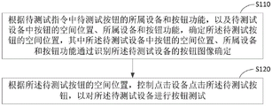
s110, determining the spatial position of the button to be tested according to the device and the button function of the button to be tested in the instruction to be tested and the spatial position, the device and the button function of the button in the device to be tested, wherein the spatial position, the device and the button function of the button in the device to be tested are determined by identifying the button image of the device to be tested.
The test instruction is used for indicating a test, and the test instruction comprises the equipment to which the button to be tested belongs and the button function.
The button to be tested refers to the button to be clicked for testing. Specifically, the button to be tested may be a volume plus button on the first sound box.
Specifically, the test instruction may be generated according to a test case.
The image position of the button refers to a position of the button in an image coordinate system to which the button image belongs.
The spatial position of the button refers to the position of the button in the spatial coordinate system used by the pointing device.
Typically, the spatial coordinate system may be a world coordinate system.
The device to which the button belongs is a device to which the button is set.
The button in the device to be tested refers to a button located in the device to be tested. In particular, the button in the device to be tested may be any button in the device to be tested.
The button image refers to an image including buttons of the device to be tested. Specifically, the button image may be acquired by an image acquisition device.
Specifically, the determining the spatial position of the button to be tested according to the device and the button function to which the button to be tested belongs in the instruction to be tested, and the spatial position, the device and the button function to which the button belongs in the device to be tested, includes:
matching the device and the button function of the button to be tested with the device and the button function of the button in the device to be tested;
and taking the spatial position of the button matched and consistent as the spatial position of the button to be tested.
Identifying the button image of the device to be tested, and determining the spatial position of the button in the device to be tested, including:
determining the image position of a button in the device to be tested according to the identification result;
and converting the image position by a coordinate system to obtain the spatial position of the button in the device to be tested.
Identifying the button image of the device to be tested, and determining the device to which the button in the device to be tested belongs, wherein the method comprises the following steps:
determining the image position or the space position of a button in the device to be tested according to the identification result;
determining the relative position relation of the buttons in the equipment to be tested according to the image position or the space position of the buttons in the equipment to be tested;
and determining the equipment to which the button in the equipment to be tested belongs according to the relative position relation.
Wherein, at least one device to be tested can be included in the button image. The buttons in the image can be associated with the devices to be tested to which the buttons belong according to the relative position relation among the buttons in the image, so that the devices to be tested included in the button image and the buttons included in the devices to be tested can be identified.
Identifying the button image of the device to be tested, and determining the button functions of the buttons in the device to be tested comprises:
determining the button function of a button in the device to be tested according to the identified button identification; or,
and determining the button functions of the buttons in the device to be tested according to the positions of the buttons in the device to be tested.
In particular, the button identification may be a function identification pattern on or near the button, such as a minus sign on a volume down button.
And S120, according to the spatial position of the button to be tested, controlling a clicking device to click the button to be tested so as to test the button of the device to be tested.
Wherein the pointing device may be any clickable button device.
Typically, the pointing device is a robotic arm.
Specifically, performing a button test on a device under test includes:
after clicking a button to be tested, detecting whether the device to be tested realizes the button function of the button to be tested;
if yes, determining that the test on the button to be tested is successful.
According to the technical scheme of the embodiment of the application, the spatial position of the button to be tested is determined according to the device and the button function of the button to be tested in the instruction to be tested and the spatial position, the device and the button function of the button in the device to be tested; and then controlling the clicking equipment to click the button to be tested based on the spatial position of the button to be tested, thereby realizing the test of the button to be tested in the instruction to be tested.
Because the spatial position of the button in the device to be tested, the device to which the button belongs and the function of the button are determined by identifying the button image of the device to be tested, the embodiment of the application has no strict requirement on the placement position of the device to be tested, and the adaptability is high. In addition, because the embodiment of the application can realize the test of the button to be tested in the instruction to be tested, the embodiment of the application can realize the automatic and flexible test of the button based on the instruction to be tested.
In order to improve the identification accuracy of the buttons, button marks are arranged on the buttons of the equipment to be tested and used for marking different buttons.
In particular, the button identifications may be different colors and/or different shapes of stickers.
Second embodiment
Fig. 2 is a flowchart of a testing method according to a second embodiment of the present application. The present embodiment adds color correction to the button image on the basis of the above-described embodiment. Referring to fig. 2, the test method provided by the embodiment of the present application includes:
s210, determining a shadow area and a highlight area in the button image according to the image brightness.
Specifically, determining a shadow region and a highlight region in a button image of a device to be tested according to image brightness comprises the following steps:
converting the button image into an HSV format, and extracting V vectors of all pixels;
and dividing the shadow area and the highlight area of the button image according to the extracted V vector.
S220, modifying the pixel value of the single color channel in the button image according to the total pixel median value of the shadow area, the pixel median value of the single color channel in the shadow area, the total pixel median value of the high light area and the pixel median value of the single color channel in the high light area so as to stretch the pixel value interval of the single color channel.
Specifically, the modifying the pixel value of the single color channel in the button image according to the total pixel median value of the shadow area, the pixel median value of the single color channel in the shadow area, the total pixel median value of the highlight area, and the pixel median value of the single color channel in the highlight area includes:
the pixel values of the individual color channels in the button image are modified according to the following formula,

wherein, VCIs the pixel value of a single color channel in the button image, C is any one of R, G, B channels, MShadow_CFor the pixel median value, M, of a single color channel in the shadow regionHighlight-CIs the pixel median value of a single color channel in the highlight region, MShadowIs the total pixel median value, M, of the shadow regionHighlightIs the total pixel median value of the highlight area.
And S230, combining the stretched color channels to obtain the button image with the corrected color.
S240, determining the spatial position of the button in the device to be tested, the device to which the button belongs and the function of the button by identifying the button image after color correction.
S250, determining the spatial position of the button to be tested according to the device and the button function of the button to be tested in the instruction to be tested, and the spatial position, the device and the button function of the button in the device to be tested.
S260, according to the spatial position of the button to be tested, clicking the button to be tested by a clicking device to test the button of the device to be tested.
According to the embodiment of the application, the pixel value interval of the single color channel in the button image is stretched according to the total pixel median of the shadow area, the pixel median of the single color channel in the shadow area, the total pixel median of the highlight area and the pixel median of the single color channel in the highlight area, so that the color correction of the button image is realized, and the identification accuracy of the button image is improved.
In order to make the corrected pixel value not bias to any color channel and further realize the smoothing of the button image, before correcting the pixel value of a single color channel in the button image, the method further comprises:
and in the shadow region or the highlight region, if the pixel median of a single color channel is greater than the total pixel median of a set multiple, taking the total pixel median as the pixel median of the color channel.
The setting multiple can be set according to actual needs, and this embodiment does not limit this.
Third embodiment
Fig. 3 is a flowchart of a testing method according to a third embodiment of the present application. The present embodiment is an alternative proposed on the basis of the above-described embodiments. Referring to fig. 3, the test method provided by the embodiment of the present application includes:
sticking stickers with set shapes of different colors (such as red, yellow, green and blue) on the buttons of the device to be tested so as to identify the buttons;
acquiring a button image of a device to be tested by using a camera;
correcting the button image, identifying the button of the device to be tested from the corrected button image based on the color and the shape of the sticker, and determining the device to which the button belongs according to the relative position relationship of the identified button;
converting the image position of the identified button into a physical space coordinate used by the mechanical arm;
determining the spatial position of the button to be tested according to the device and the button function of the button to be tested in the test instruction, and the device, the spatial position and the button function of the button in the device to be tested; and controlling the mechanical arm to click the button to be tested according to the spatial position of the button to be tested, thereby realizing the operation of the hardware equipment.
Specifically, correcting the deformation includes:
measuring the actual physical size of a photographing area of the camera and the physical coordinates of four corners of the photographing area;
and according to the measurement result, performing trapezoidal deformation and scaling on the shot picture so as to restore the shape of the shot picture to the shape seen right above the equipment.
Referring to fig. 4, in particular, correcting color includes:
1. firstly, converting a shot button image into an HSV format, extracting V vectors of all pixels in the button image, and arranging the V vectors according to the size sequence. And taking the pixel to which the V vector with the set proportion belongs as a shadow region in the descending order according to the sorting result, and taking the pixel to which the V vector with the set proportion belongs as a highlight region in the descending order.
2. The total pixel median value of the pixel values in all color channels (R, G, and B channels) of the shaded region and the pixel median value of the pixel values in a single color channel (R, G, or B channel) of the shaded region are calculated. And if the pixel median value of the single color channel is greater than 2 times of the total pixel median value, the pixel median value of the single color channel is equal to the total pixel median value.
3. The total pixel median value of all pixel values in all color channels (R-channel, G-channel, and B-channel) of the highlight region and the pixel median value of the pixel value in a single color channel (R-channel, G-channel, or B-channel) of the highlight region are calculated. And if the pixel median value of the single color channel is greater than 2 times of the total pixel median value, the pixel median value of the single color channel is equal to the total pixel median value.
4. The pixel values in each color channel in the button image are corrected according to the following formula:

wherein, VCIs the pixel value of a single color channel in the button image, C is any one of R, G, B channels, MShadow_CFor the pixel median value, M, of a single color channel in the shadow regionHighlight_CIs a single color in the highlight regionPixel median value, M, of the color channelShadowIs the total pixel median value, M, of the shadow regionHjghlightIs the total pixel median value of the highlight area. If the last calculated VCIf the value is greater than 255, it is equal to 255, if the last calculated V isCValues less than 0 are equal to 0.
5. And combining the stretched color channels to obtain the button image with the corrected color.
Specifically, the color recognition of the button image includes:
the button image is converted into HSV format and the corresponding color is extracted from the values of the three vectors H, S, V.
Referring to fig. 5, specifically, the shape recognition of the button image includes:
firstly, carrying out median blurring on a button image to reduce details;
then calculating a histogram of the button image, and smoothing the histogram of the set step length according to the histogram;
deriving the smoothed histogram, finding out a maximum length interval in which the absolute value of the derivative is smaller than a set threshold value, and calculating the median of the length interval;
binarizing the button image by using the obtained value as a threshold value;
corroding the binarized button image by using a convolution kernel with a set size to filter image noise;
and searching the edge of the corroded image result, and performing circle detection according to the edge search result.
Specifically, according to the spatial position of the button to be tested, a clicking device is controlled to click the button to be tested:
and transmitting the spatial position of the button to be tested to the programmable mechanical arm, controlling the programmable mechanical arm to move to the coordinate of the spatial position, and performing descending click operation.
According to the technical scheme of the embodiment of the application, the button position of the hardware equipment is automatically identified through an image identification method and is given to the mechanical arm for automatic clicking. Meanwhile, the functions of different buttons can be distinguished in advance through stickers with different colors. Therefore, programmable automatic testing can be realized in the embodiment of the application, and when the equipment changes, self-adaptation can be carried out by replacing the paster, no strict requirement is required on the placing position of the equipment, and the adaptability is higher.
Fourth embodiment
Fig. 6 is a schematic structural diagram of a testing apparatus according to a fourth embodiment of the present application. Referring to fig. 6, a test apparatus 600 provided in an embodiment of the present application includes: a position determination module 601 and a button click module 602.
The position determining module 601 is configured to determine a spatial position of a button to be tested according to a device and a button function to which the button to be tested belongs in a command to be tested, and a spatial position, a device and a button function of the button in the device to be tested, where the spatial position, the device and the button function of the button in the device to be tested are determined by identifying a button image of the device to be tested;
and the button clicking module 602 is configured to control a clicking device to click the button to be tested according to the spatial position of the button to be tested, so as to perform a button test on the device to be tested.
According to the technical scheme of the embodiment of the application, the spatial position of the button to be tested is determined according to the device and the button function of the button to be tested in the instruction to be tested and the spatial position, the device and the button function of the button in the device to be tested; and then controlling the clicking equipment to click the button to be tested based on the spatial position of the button to be tested, thereby realizing the test of the button to be tested in the instruction to be tested.
Because the spatial position of the button in the device to be tested, the device to which the button belongs and the function of the button are determined by identifying the button image of the device to be tested, the embodiment of the application has no strict requirement on the placement position of the device to be tested, and the adaptability is high. In addition, because the embodiment of the application can realize the test of the button to be tested in the instruction to be tested, the embodiment of the application can realize the automatic and flexible test of the button based on the instruction to be tested.
Further, the position determination module includes:
the button matching unit is used for matching the device and the button function of the button to be tested with the device and the button function of the button in the device to be tested;
and the position determining unit is used for taking the spatial position of the button matched and consistent as the spatial position of the button to be tested.
Further, the position determination module includes:
the position determining unit is used for determining the image position of the button in the device to be tested according to the identification result;
and the coordinate conversion unit is used for carrying out coordinate system conversion on the image position to obtain the spatial position of the button in the device to be tested.
Further, the position determination module includes:
the position determining unit is used for determining the image position or the space position of a button in the device to be tested according to the identification result;
the relation determining unit is used for determining the relative position relation of the buttons in the equipment to be tested according to the image position or the space position of the buttons in the equipment to be tested;
and the affiliated device determining unit is used for determining the affiliated device of the button in the device to be tested according to the relative position relation of the button in the device to be tested.
Further, the apparatus further comprises:
the area determining module is used for determining a shadow area and a highlight area in the button image according to the image brightness before identifying the button image of the device to be tested;
the interval stretching module is used for modifying the pixel value of the single color channel in the button image according to the total pixel median value of the shadow area, the pixel median value of the single color channel in the shadow area, the total pixel median value of the high light area and the pixel median value of the single color channel in the high light area so as to stretch the pixel value interval of the single color channel;
and the channel merging module is used for merging the stretched color channels to obtain the button image with corrected color.
Further, the span stretching module comprises:
a pixel value correction unit for correcting the pixel values of the individual color channels in the button image according to the following formula,

wherein, VCIs the pixel value of a single color channel in the button image, C is any one of R, G, B channels, MShadow_CFor the pixel median value, M, of a single color channel in the shadow regionHighlight_CIs the pixel median value of a single color channel in the highlight region, MShadowIs the total pixel median value, M, of the shadow regionHighlightIs the total pixel median value of the highlight area.
Further, the apparatus further comprises:
and the pixel median value determining module is used for taking the total pixel median value as the pixel median value of the color channel in the shadow area or the highlight area if the pixel median value of the single color channel is greater than the total pixel median value of the set multiple before correcting the pixel median value of the single color channel in the button image.
Fifth embodiment
According to an embodiment of the present application, an electronic device and a readable storage medium are also provided.
Fig. 7 is a block diagram of an electronic device according to the testing method of the embodiment of the present application. Electronic devices are intended to represent various forms of digital computers, such as laptops, desktops, workstations, personal digital assistants, servers, blade servers, mainframes, and other appropriate computers. The electronic device may also represent various forms of mobile devices, such as personal digital processing, cellular phones, smart phones, wearable devices, and other similar computing devices. The components shown herein, their connections and relationships, and their functions, are meant to be examples only, and are not meant to limit implementations of the present application that are described and/or claimed herein.
As shown in fig. 7, the electronic apparatus includes: one or more processors 701, a memory 702, and interfaces for connecting the various components, including a high-speed interface and a low-speed interface. The various components are interconnected using different buses and may be mounted on a common motherboard or in other manners as desired. The processor may process instructions for execution within the electronic device, including instructions stored in or on the memory to display graphical information of a GUI on an external input/output apparatus (such as a display device coupled to the interface). In other embodiments, multiple processors and/or multiple buses may be used, along with multiple memories and multiple memories, as desired. Also, multiple electronic devices may be connected, with each device providing portions of the necessary operations (e.g., as a server array, a group of blade servers, or a multi-processor system). In fig. 7, one processor 701 is taken as an example.
The memory 702 is a non-transitory computer readable storage medium as provided herein. The memory stores instructions executable by at least one processor to cause the at least one processor to perform the testing method provided herein. The non-transitory computer readable storage medium of the present application stores computer instructions for causing a computer to perform the testing method provided herein.
The memory 702 may include a storage program area and a storage data area, wherein the storage program area may store an operating system, an application program required for at least one function; the storage data area may store data created according to use of the test electronic device, and the like. Further, the memory 702 may include high speed random access memory, and may also include non-transitory memory, such as at least one magnetic disk storage device, flash memory device, or other non-transitory solid state storage device. In some embodiments, the memory 702 may optionally include memory located remotely from the processor 701, which may be connected to the test electronics over a network. Examples of such networks include, but are not limited to, the internet, intranets, blockchain networks, local area networks, mobile communication networks, and combinations thereof.
The electronic device of the test method may further include: an input device 703 and an output device 704. The processor 701, the memory 702, the input device 703 and the output device 704 may be connected by a bus or other means, and fig. 7 illustrates an example of a connection by a bus.
The input device 703 may receive input numeric or character information and generate key signal inputs related to user settings and function controls of the test electronic device, such as a touch screen, keypad, mouse, track pad, touch pad, pointer stick, one or more mouse buttons, track ball, joystick, or other input device. The output devices 704 may include a display device, auxiliary lighting devices (e.g., LEDs), and tactile feedback devices (e.g., vibrating motors), among others. The display device may include, but is not limited to, a Liquid Crystal Display (LCD), a Light Emitting Diode (LED) display, and a plasma display. In some implementations, the display device can be a touch screen.
Various implementations of the systems and techniques described here can be realized in digital electronic circuitry, integrated circuitry, application specific ASICs (application specific integrated circuits), computer hardware, firmware, software, and/or combinations thereof. These various embodiments may include: implemented in one or more computer programs that are executable and/or interpretable on a programmable system including at least one programmable processor, which may be special or general purpose, receiving data and instructions from, and transmitting data and instructions to, a storage system, at least one input device, and at least one output device.
These computer programs (also known as programs, software applications, or code) include machine instructions for a programmable processor, and may be implemented using high-level procedural and/or object-oriented programming languages, and/or assembly/machine languages. As used herein, the terms "machine-readable medium" and "computer-readable medium" refer to any computer program product, apparatus, and/or device (e.g., magnetic discs, optical disks, memory, Programmable Logic Devices (PLDs)) used to provide machine instructions and/or data to a programmable processor, including a machine-readable medium that receives machine instructions as a machine-readable signal. The term "machine-readable signal" refers to any signal used to provide machine instructions and/or data to a programmable processor.
To provide for interaction with a user, the systems and techniques described here can be implemented on a computer having: a display device (e.g., a CRT (cathode ray tube) or LCD (liquid crystal display) monitor) for displaying information to a user; and a keyboard and a pointing device (e.g., a mouse or a trackball) by which a user can provide input to the computer. Other kinds of devices may also be used to provide for interaction with a user; for example, feedback provided to the user can be any form of sensory feedback (e.g., visual feedback, auditory feedback, or tactile feedback); and input from the user may be received in any form, including acoustic, speech, or tactile input.
The systems and techniques described here can be implemented in a computing system that includes a back-end component (e.g., as a data server), or that includes a middleware component (e.g., an application server), or that includes a front-end component (e.g., a user computer having a graphical user interface or a web browser through which a user can interact with an implementation of the systems and techniques described here), or any combination of such back-end, middleware, or front-end components. The components of the system can be interconnected by any form or medium of digital data communication (e.g., a communication network). Examples of communication networks include: local Area Networks (LANs), Wide Area Networks (WANs), the internet, and blockchain networks.
The computer system may include clients and servers. A client and server are generally remote from each other and typically interact through a communication network. The relationship of client and server arises by virtue of computer programs running on the respective computers and having a client-server relationship to each other.
It should be understood that various forms of the flows shown above may be used, with steps reordered, added, or deleted. For example, the steps described in the present application may be executed in parallel, sequentially, or in different orders, and the present invention is not limited thereto as long as the desired results of the technical solutions disclosed in the present application can be achieved.
The above-described embodiments should not be construed as limiting the scope of the present application. It should be understood by those skilled in the art that various modifications, combinations, sub-combinations and substitutions may be made in accordance with design requirements and other factors. Any modification, equivalent replacement, and improvement made within the spirit and principle of the present application shall be included in the protection scope of the present application.
Claims (15)
1. A method of testing, comprising:
determining the spatial position of a button to be tested according to the device and the button function of the button to be tested in the instruction to be tested and the spatial position, the device and the button function of the button in the device to be tested, wherein the spatial position, the device and the button function of the button in the device to be tested are determined by identifying the button image of the device to be tested;
and controlling a clicking device to click the button to be tested according to the spatial position of the button to be tested so as to test the button of the device to be tested.
2. The method of claim 1, wherein determining the spatial position of the button to be tested according to the device and the button function to which the button to be tested belongs in the instruction to be tested and the spatial position of the button in the device to be tested, the device and the button function to which the button belongs comprises:
matching the device and the button function of the button to be tested with the device and the button function of the button in the device to be tested;
and taking the spatial position of the button matched and consistent as the spatial position of the button to be tested.
3. The method of claim 1, wherein identifying button images of the device under test, determining spatial locations of buttons in the device under test, comprises:
determining the image position of a button in the device to be tested according to the identification result;
and converting the image position by a coordinate system to obtain the spatial position of the button in the device to be tested.
4. The method of claim 1, wherein identifying button images of the devices under test, determining the device to which a button in the devices under test belongs, comprises:
determining the image position or the space position of a button in the device to be tested according to the identification result;
determining the relative position relation of the buttons in the equipment to be tested according to the image position or the space position of the buttons in the equipment to be tested;
and determining the equipment to which the button in the equipment to be tested belongs according to the relative position relation.
5. The method of claim 1, wherein prior to identifying the button image of the device under test, the method further comprises:
determining a shadow region and a highlight region in the button image according to the image brightness;
modifying the pixel value of the single color channel in the button image according to the total pixel median value of the shadow area, the pixel median value of the single color channel in the shadow area, the total pixel median value of the highlight area and the pixel median value of the single color channel in the highlight area so as to stretch the pixel value interval of the single color channel;
and combining the stretched color channels to obtain the button image with the corrected color.
6. The method according to claim 5, wherein the modifying the pixel values of the individual color channels in the button image according to the median total pixel value of the shaded area, the median total pixel value of the individual color channels in the shaded area, the median total pixel value of the highlight area, and the median total pixel value of the individual color channels in the highlight area comprises:
the pixel values of the individual color channels in the button image are modified according to the following formula,

wherein, VCIs the pixel value of a single color channel in the button image, C is any one of R, G, B channels, MShadow_CFor the pixel median value, M, of a single color channel in the shadow regionHighlight_CIs the pixel median value of a single color channel in the highlight region, MShadowIs the total pixel median value, M, of the shadow regionHighlightIs the total pixel median value of the highlight area.
7. The method of claim 5, wherein before modifying the pixel values of the individual color channels in the button image, the method further comprises:
and in the shadow region or the highlight region, if the pixel median of a single color channel is greater than the total pixel median of a set multiple, taking the total pixel median as the pixel median of the color channel.
8. A test apparatus, comprising:
the position determining module is used for determining the spatial position of the button to be tested according to the device and the button function of the button to be tested in the instruction to be tested and the spatial position, the device and the button function of the button in the device to be tested, wherein the spatial position, the device and the button function of the button in the device to be tested are determined by identifying the button image of the device to be tested;
and the button clicking module is used for controlling clicking equipment to click the button to be tested according to the spatial position of the button to be tested so as to test the button of the equipment to be tested.
9. The apparatus of claim 8, wherein the location determination module comprises:
the button matching unit is used for matching the device and the button function of the button to be tested with the device and the button function of the button in the device to be tested;
and the position determining unit is used for taking the spatial position of the button matched and consistent as the spatial position of the button to be tested.
10. The apparatus of claim 8, wherein the location determination module comprises:
the position determining unit is used for determining the image position of the button in the device to be tested according to the identification result;
and the coordinate conversion unit is used for carrying out coordinate system conversion on the image position to obtain the spatial position of the button in the device to be tested.
11. The apparatus of claim 8, wherein the location determination module comprises:
the position determining unit is used for determining the image position or the space position of a button in the device to be tested according to the identification result;
the relation determining unit is used for determining the relative position relation of the buttons in the equipment to be tested according to the image position or the space position of the buttons in the equipment to be tested;
and the affiliated device determining unit is used for determining the affiliated device of the button in the device to be tested according to the relative position relation of the button in the device to be tested.
12. The apparatus of claim 8, further comprising:
the area determining module is used for determining a shadow area and a highlight area in the button image according to the image brightness before identifying the button image of the device to be tested;
the interval stretching module is used for modifying the pixel value of the single color channel in the button image according to the total pixel median value of the shadow area, the pixel median value of the single color channel in the shadow area, the total pixel median value of the high light area and the pixel median value of the single color channel in the high light area so as to stretch the pixel value interval of the single color channel;
and the channel merging module is used for merging the stretched color channels to obtain the button image with corrected color.
13. The apparatus of claim 12, wherein the span stretching module comprises:
a pixel value correction unit for correcting the pixel values of the individual color channels in the button image according to the following formula,

wherein, VCIs the pixel value of a single color channel in the button image, C is any one of R, G, B channels, MShadow_CFor the pixel median value, M, of a single color channel in the shadow regionHighlight_CIs the pixel median value of a single color channel in the highlight region, MShadowIs the total pixel median value, M, of the shadow regionHighlightIs the total pixel median value of the highlight area.
14. An electronic device, comprising:
at least one processor; and
a memory communicatively coupled to the at least one processor; wherein,
the memory stores instructions executable by the at least one processor to enable the at least one processor to perform the method of any one of claims 1-7.
15. A non-transitory computer readable storage medium having stored thereon computer instructions for causing the computer to perform the method of any one of claims 1-7.
Priority Applications (1)
| Application Number | Priority Date | Filing Date | Title |
|---|---|---|---|
| CN202010003346.2A CN111208417B (en) | 2020-01-02 | 2020-01-02 | Test method, device, equipment and medium |
Applications Claiming Priority (1)
| Application Number | Priority Date | Filing Date | Title |
|---|---|---|---|
| CN202010003346.2A CN111208417B (en) | 2020-01-02 | 2020-01-02 | Test method, device, equipment and medium |
Publications (2)
| Publication Number | Publication Date |
|---|---|
| CN111208417A true CN111208417A (en) | 2020-05-29 |
| CN111208417B CN111208417B (en) | 2022-11-11 |
Family
ID=70785877
Family Applications (1)
| Application Number | Title | Priority Date | Filing Date |
|---|---|---|---|
| CN202010003346.2A Active CN111208417B (en) | 2020-01-02 | 2020-01-02 | Test method, device, equipment and medium |
Country Status (1)
| Country | Link |
|---|---|
| CN (1) | CN111208417B (en) |
Citations (10)
| Publication number | Priority date | Publication date | Assignee | Title |
|---|---|---|---|---|
| KR20080046928A (en) * | 2006-11-23 | 2008-05-28 | 주식회사 대우일렉트로닉스 | Apparatus and method for detecting location of remote controller |
| CN102116842A (en) * | 2009-12-31 | 2011-07-06 | 比亚迪股份有限公司 | System and method for detecting electric property of assembled keys |
| CN202351344U (en) * | 2011-11-10 | 2012-07-25 | 深圳市兆驰股份有限公司 | Automatic life aging testing platform of remote controller |
| CN103354660A (en) * | 2013-06-21 | 2013-10-16 | 北京邮电大学 | Positioning method and device based on signal intensity in mobile communication network |
| JP2014030496A (en) * | 2012-08-01 | 2014-02-20 | Juki Corp | Method for detecting button direction, device for detecting button direction, and device for feeding button |
| CN105653056A (en) * | 2015-12-17 | 2016-06-08 | 北京奇虎科技有限公司 | Input method test method and device |
| CN107507138A (en) * | 2017-07-27 | 2017-12-22 | 北京大学深圳研究生院 | A kind of underwater picture Enhancement Method based on Retinex model |
| CN110154026A (en) * | 2019-05-24 | 2019-08-23 | 合肥工业大学 | Rail traction substation operates robot control system and control method |
| CN110310332A (en) * | 2019-06-26 | 2019-10-08 | 珠海格力智能装备有限公司 | Key calibration method and device |
| CN110413529A (en) * | 2019-07-31 | 2019-11-05 | 中国工商银行股份有限公司 | Applied to the test method of electronic equipment, device, calculate equipment and medium |
-
2020
- 2020-01-02 CN CN202010003346.2A patent/CN111208417B/en active Active
Patent Citations (10)
| Publication number | Priority date | Publication date | Assignee | Title |
|---|---|---|---|---|
| KR20080046928A (en) * | 2006-11-23 | 2008-05-28 | 주식회사 대우일렉트로닉스 | Apparatus and method for detecting location of remote controller |
| CN102116842A (en) * | 2009-12-31 | 2011-07-06 | 比亚迪股份有限公司 | System and method for detecting electric property of assembled keys |
| CN202351344U (en) * | 2011-11-10 | 2012-07-25 | 深圳市兆驰股份有限公司 | Automatic life aging testing platform of remote controller |
| JP2014030496A (en) * | 2012-08-01 | 2014-02-20 | Juki Corp | Method for detecting button direction, device for detecting button direction, and device for feeding button |
| CN103354660A (en) * | 2013-06-21 | 2013-10-16 | 北京邮电大学 | Positioning method and device based on signal intensity in mobile communication network |
| CN105653056A (en) * | 2015-12-17 | 2016-06-08 | 北京奇虎科技有限公司 | Input method test method and device |
| CN107507138A (en) * | 2017-07-27 | 2017-12-22 | 北京大学深圳研究生院 | A kind of underwater picture Enhancement Method based on Retinex model |
| CN110154026A (en) * | 2019-05-24 | 2019-08-23 | 合肥工业大学 | Rail traction substation operates robot control system and control method |
| CN110310332A (en) * | 2019-06-26 | 2019-10-08 | 珠海格力智能装备有限公司 | Key calibration method and device |
| CN110413529A (en) * | 2019-07-31 | 2019-11-05 | 中国工商银行股份有限公司 | Applied to the test method of electronic equipment, device, calculate equipment and medium |
Non-Patent Citations (1)
| Title |
|---|
| 方志强等: "获取目标姿态的图像匹配方法研究", 《制造业自动化》 * |
Also Published As
| Publication number | Publication date |
|---|---|
| CN111208417B (en) | 2022-11-11 |
Similar Documents
| Publication | Publication Date | Title |
|---|---|---|
| US20210209802A1 (en) | Image Detection Method, Apparatus, Electronic Device and Storage Medium | |
| CN111986178A (en) | Product defect detection method and device, electronic equipment and storage medium | |
| CN111523468B (en) | Human body key point identification method and device | |
| CN111931591A (en) | Method and device for constructing key point learning model, electronic equipment and readable storage medium | |
| CN111833303A (en) | Product detection method and device, electronic equipment and storage medium | |
| CN110458826B (en) | Ambient brightness detection method and device | |
| CN111612820A (en) | Multi-target tracking method, and training method and device of feature extraction model | |
| CN106951346A (en) | The method of testing and device of a kind of response time | |
| CN111857334B (en) | Human gesture letter recognition method and device, computer equipment and storage medium | |
| CN107895377B (en) | Foreground target extraction method, device, equipment and storage medium | |
| CN108881875B (en) | Image white balance processing method and device, storage medium and terminal | |
| CN109359043B (en) | Mobile game automatic testing method based on machine learning | |
| CN110609912B (en) | Component information recording method, device, equipment and readable storage medium | |
| CN111640103B (en) | Image detection method, device, equipment and storage medium | |
| CN111862030B (en) | Face synthetic image detection method and device, electronic equipment and storage medium | |
| CN111739069B (en) | Image registration method, device, electronic equipment and readable storage medium | |
| CN111611903A (en) | Training method, using method, device, equipment and medium of motion recognition model | |
| CN110659600A (en) | Object detection method, device and equipment | |
| JP2019075130A (en) | Information processing unit, control method, program | |
| CN110263608B (en) | Automatic electronic component identification method based on image feature space variable threshold measurement | |
| CN112559341A (en) | Picture testing method, device, equipment and storage medium | |
| CN108830820B (en) | Electronic device, image acquisition method, and computer-readable storage medium | |
| CN111819567A (en) | Method and apparatus for matching images using semantic features | |
| CN112036315A (en) | Character recognition method, character recognition device, electronic equipment and storage medium | |
| CN111652103A (en) | Indoor positioning method, device, equipment and storage medium |
Legal Events
| Date | Code | Title | Description |
|---|---|---|---|
| PB01 | Publication | ||
| PB01 | Publication | ||
| SE01 | Entry into force of request for substantive examination | ||
| SE01 | Entry into force of request for substantive examination | ||
| GR01 | Patent grant | ||
| GR01 | Patent grant |