CN110728158A - Apparatus and system for triggering a mobile scanning device - Google Patents
Apparatus and system for triggering a mobile scanning device Download PDFInfo
- Publication number
- CN110728158A CN110728158A CN201810783869.6A CN201810783869A CN110728158A CN 110728158 A CN110728158 A CN 110728158A CN 201810783869 A CN201810783869 A CN 201810783869A CN 110728158 A CN110728158 A CN 110728158A
- Authority
- CN
- China
- Prior art keywords
- glove
- conductive
- conductive pad
- scanning device
- woven
- Prior art date
- Legal status (The legal status is an assumption and is not a legal conclusion. Google has not performed a legal analysis and makes no representation as to the accuracy of the status listed.)
- Granted
Links
- 238000004891 communication Methods 0.000 claims abstract description 48
- 230000001960 triggered effect Effects 0.000 claims abstract description 7
- 238000000034 method Methods 0.000 claims description 27
- 239000011248 coating agent Substances 0.000 claims description 15
- 238000000576 coating method Methods 0.000 claims description 15
- BQCADISMDOOEFD-UHFFFAOYSA-N Silver Chemical compound [Ag] BQCADISMDOOEFD-UHFFFAOYSA-N 0.000 claims description 4
- -1 polyethylene Polymers 0.000 claims description 4
- 239000004332 silver Substances 0.000 claims description 4
- 229910052709 silver Inorganic materials 0.000 claims description 4
- 239000004677 Nylon Substances 0.000 claims description 2
- 239000004698 Polyethylene Substances 0.000 claims description 2
- 229920001778 nylon Polymers 0.000 claims description 2
- 229920000573 polyethylene Polymers 0.000 claims description 2
- 229920000728 polyester Polymers 0.000 claims 1
- 210000003811 finger Anatomy 0.000 description 62
- 210000003813 thumb Anatomy 0.000 description 12
- 238000010586 diagram Methods 0.000 description 11
- 230000006870 function Effects 0.000 description 8
- 238000005286 illumination Methods 0.000 description 6
- 229920001971 elastomer Polymers 0.000 description 4
- 238000005516 engineering process Methods 0.000 description 4
- 229920001084 poly(chloroprene) Polymers 0.000 description 4
- 230000009471 action Effects 0.000 description 3
- 230000008878 coupling Effects 0.000 description 3
- 238000010168 coupling process Methods 0.000 description 3
- 238000005859 coupling reaction Methods 0.000 description 3
- 238000003384 imaging method Methods 0.000 description 3
- 238000009940 knitting Methods 0.000 description 3
- 238000004519 manufacturing process Methods 0.000 description 3
- 238000012986 modification Methods 0.000 description 3
- 230000004048 modification Effects 0.000 description 3
- 230000003287 optical effect Effects 0.000 description 3
- 238000012545 processing Methods 0.000 description 3
- RRHGJUQNOFWUDK-UHFFFAOYSA-N Isoprene Chemical compound CC(=C)C=C RRHGJUQNOFWUDK-UHFFFAOYSA-N 0.000 description 2
- 230000005540 biological transmission Effects 0.000 description 2
- 210000004247 hand Anatomy 0.000 description 2
- 229920000126 latex Polymers 0.000 description 2
- 239000004816 latex Substances 0.000 description 2
- 239000000463 material Substances 0.000 description 2
- 150000002825 nitriles Chemical class 0.000 description 2
- 229920002635 polyurethane Polymers 0.000 description 2
- 239000004814 polyurethane Substances 0.000 description 2
- 239000011118 polyvinyl acetate Substances 0.000 description 2
- 239000004800 polyvinyl chloride Substances 0.000 description 2
- 230000004044 response Effects 0.000 description 2
- 239000007787 solid Substances 0.000 description 2
- 238000009941 weaving Methods 0.000 description 2
- 230000003213 activating effect Effects 0.000 description 1
- 238000007792 addition Methods 0.000 description 1
- 230000003321 amplification Effects 0.000 description 1
- 230000008901 benefit Effects 0.000 description 1
- 238000004590 computer program Methods 0.000 description 1
- 239000004020 conductor Substances 0.000 description 1
- 230000007423 decrease Effects 0.000 description 1
- 230000007812 deficiency Effects 0.000 description 1
- 238000011161 development Methods 0.000 description 1
- 210000005224 forefinger Anatomy 0.000 description 1
- 239000004973 liquid crystal related substance Substances 0.000 description 1
- 239000000203 mixture Substances 0.000 description 1
- 239000012811 non-conductive material Substances 0.000 description 1
- 238000003199 nucleic acid amplification method Methods 0.000 description 1
- 229920003023 plastic Polymers 0.000 description 1
- 239000004033 plastic Substances 0.000 description 1
- 230000008569 process Effects 0.000 description 1
- 210000001525 retina Anatomy 0.000 description 1
- 210000000707 wrist Anatomy 0.000 description 1
Images


Classifications
-
- A—HUMAN NECESSITIES
- A41—WEARING APPAREL
- A41D—OUTERWEAR; PROTECTIVE GARMENTS; ACCESSORIES
- A41D19/00—Gloves
- A41D19/0024—Gloves with accessories
- A41D19/0027—Measuring instruments, e.g. watch, thermometer
-
- A—HUMAN NECESSITIES
- A41—WEARING APPAREL
- A41D—OUTERWEAR; PROTECTIVE GARMENTS; ACCESSORIES
- A41D19/00—Gloves
- A41D19/0024—Gloves with accessories
-
- G—PHYSICS
- G06—COMPUTING; CALCULATING OR COUNTING
- G06K—GRAPHICAL DATA READING; PRESENTATION OF DATA; RECORD CARRIERS; HANDLING RECORD CARRIERS
- G06K7/00—Methods or arrangements for sensing record carriers, e.g. for reading patterns
- G06K7/10—Methods or arrangements for sensing record carriers, e.g. for reading patterns by electromagnetic radiation, e.g. optical sensing; by corpuscular radiation
- G06K7/10544—Methods or arrangements for sensing record carriers, e.g. for reading patterns by electromagnetic radiation, e.g. optical sensing; by corpuscular radiation by scanning of the records by radiation in the optical part of the electromagnetic spectrum
- G06K7/10821—Methods or arrangements for sensing record carriers, e.g. for reading patterns by electromagnetic radiation, e.g. optical sensing; by corpuscular radiation by scanning of the records by radiation in the optical part of the electromagnetic spectrum further details of bar or optical code scanning devices
- G06K7/10881—Methods or arrangements for sensing record carriers, e.g. for reading patterns by electromagnetic radiation, e.g. optical sensing; by corpuscular radiation by scanning of the records by radiation in the optical part of the electromagnetic spectrum further details of bar or optical code scanning devices constructional details of hand-held scanners
- G06K7/10891—Methods or arrangements for sensing record carriers, e.g. for reading patterns by electromagnetic radiation, e.g. optical sensing; by corpuscular radiation by scanning of the records by radiation in the optical part of the electromagnetic spectrum further details of bar or optical code scanning devices constructional details of hand-held scanners the scanner to be worn on a finger or on a wrist
-
- A—HUMAN NECESSITIES
- A41—WEARING APPAREL
- A41D—OUTERWEAR; PROTECTIVE GARMENTS; ACCESSORIES
- A41D19/00—Gloves
- A41D19/0034—Retaining means
- A41D19/0037—Retaining means for fastening an article to the glove
-
- G—PHYSICS
- G06—COMPUTING; CALCULATING OR COUNTING
- G06F—ELECTRIC DIGITAL DATA PROCESSING
- G06F1/00—Details not covered by groups G06F3/00 - G06F13/00 and G06F21/00
- G06F1/16—Constructional details or arrangements
- G06F1/1613—Constructional details or arrangements for portable computers
- G06F1/163—Wearable computers, e.g. on a belt
-
- G—PHYSICS
- G06—COMPUTING; CALCULATING OR COUNTING
- G06F—ELECTRIC DIGITAL DATA PROCESSING
- G06F3/00—Input arrangements for transferring data to be processed into a form capable of being handled by the computer; Output arrangements for transferring data from processing unit to output unit, e.g. interface arrangements
- G06F3/01—Input arrangements or combined input and output arrangements for interaction between user and computer
- G06F3/011—Arrangements for interaction with the human body, e.g. for user immersion in virtual reality
- G06F3/014—Hand-worn input/output arrangements, e.g. data gloves
-
- G—PHYSICS
- G06—COMPUTING; CALCULATING OR COUNTING
- G06F—ELECTRIC DIGITAL DATA PROCESSING
- G06F3/00—Input arrangements for transferring data to be processed into a form capable of being handled by the computer; Output arrangements for transferring data from processing unit to output unit, e.g. interface arrangements
- G06F3/01—Input arrangements or combined input and output arrangements for interaction between user and computer
- G06F3/017—Gesture based interaction, e.g. based on a set of recognized hand gestures
-
- G—PHYSICS
- G06—COMPUTING; CALCULATING OR COUNTING
- G06F—ELECTRIC DIGITAL DATA PROCESSING
- G06F3/00—Input arrangements for transferring data to be processed into a form capable of being handled by the computer; Output arrangements for transferring data from processing unit to output unit, e.g. interface arrangements
- G06F3/01—Input arrangements or combined input and output arrangements for interaction between user and computer
- G06F3/03—Arrangements for converting the position or the displacement of a member into a coded form
- G06F3/033—Pointing devices displaced or positioned by the user, e.g. mice, trackballs, pens or joysticks; Accessories therefor
- G06F3/038—Control and interface arrangements therefor, e.g. drivers or device-embedded control circuitry
-
- G—PHYSICS
- G06—COMPUTING; CALCULATING OR COUNTING
- G06K—GRAPHICAL DATA READING; PRESENTATION OF DATA; RECORD CARRIERS; HANDLING RECORD CARRIERS
- G06K7/00—Methods or arrangements for sensing record carriers, e.g. for reading patterns
- G06K7/10—Methods or arrangements for sensing record carriers, e.g. for reading patterns by electromagnetic radiation, e.g. optical sensing; by corpuscular radiation
- G06K7/10009—Methods or arrangements for sensing record carriers, e.g. for reading patterns by electromagnetic radiation, e.g. optical sensing; by corpuscular radiation sensing by radiation using wavelengths larger than 0.1 mm, e.g. radio-waves or microwaves
- G06K7/10366—Methods or arrangements for sensing record carriers, e.g. for reading patterns by electromagnetic radiation, e.g. optical sensing; by corpuscular radiation sensing by radiation using wavelengths larger than 0.1 mm, e.g. radio-waves or microwaves the interrogation device being adapted for miscellaneous applications
- G06K7/10376—Methods or arrangements for sensing record carriers, e.g. for reading patterns by electromagnetic radiation, e.g. optical sensing; by corpuscular radiation sensing by radiation using wavelengths larger than 0.1 mm, e.g. radio-waves or microwaves the interrogation device being adapted for miscellaneous applications the interrogation device being adapted for being moveable
- G06K7/10396—Methods or arrangements for sensing record carriers, e.g. for reading patterns by electromagnetic radiation, e.g. optical sensing; by corpuscular radiation sensing by radiation using wavelengths larger than 0.1 mm, e.g. radio-waves or microwaves the interrogation device being adapted for miscellaneous applications the interrogation device being adapted for being moveable the interrogation device being wearable, e.g. as a glove, bracelet, or ring
-
- G—PHYSICS
- G06—COMPUTING; CALCULATING OR COUNTING
- G06K—GRAPHICAL DATA READING; PRESENTATION OF DATA; RECORD CARRIERS; HANDLING RECORD CARRIERS
- G06K7/00—Methods or arrangements for sensing record carriers, e.g. for reading patterns
- G06K7/10—Methods or arrangements for sensing record carriers, e.g. for reading patterns by electromagnetic radiation, e.g. optical sensing; by corpuscular radiation
- G06K7/10544—Methods or arrangements for sensing record carriers, e.g. for reading patterns by electromagnetic radiation, e.g. optical sensing; by corpuscular radiation by scanning of the records by radiation in the optical part of the electromagnetic spectrum
- G06K7/10554—Moving beam scanning
- G06K7/10594—Beam path
- G06K7/10603—Basic scanning using moving elements
-
- G—PHYSICS
- G06—COMPUTING; CALCULATING OR COUNTING
- G06K—GRAPHICAL DATA READING; PRESENTATION OF DATA; RECORD CARRIERS; HANDLING RECORD CARRIERS
- G06K7/00—Methods or arrangements for sensing record carriers, e.g. for reading patterns
- G06K7/10—Methods or arrangements for sensing record carriers, e.g. for reading patterns by electromagnetic radiation, e.g. optical sensing; by corpuscular radiation
- G06K2007/10524—Hand-held scanners
- G06K2007/10534—Scanner to be worn on a finger or on a wrist
-
- G—PHYSICS
- G06—COMPUTING; CALCULATING OR COUNTING
- G06Q—INFORMATION AND COMMUNICATION TECHNOLOGY [ICT] SPECIALLY ADAPTED FOR ADMINISTRATIVE, COMMERCIAL, FINANCIAL, MANAGERIAL OR SUPERVISORY PURPOSES; SYSTEMS OR METHODS SPECIALLY ADAPTED FOR ADMINISTRATIVE, COMMERCIAL, FINANCIAL, MANAGERIAL OR SUPERVISORY PURPOSES, NOT OTHERWISE PROVIDED FOR
- G06Q10/00—Administration; Management
- G06Q10/08—Logistics, e.g. warehousing, loading or distribution; Inventory or stock management
- G06Q10/087—Inventory or stock management, e.g. order filling, procurement or balancing against orders
Landscapes
- Engineering & Computer Science (AREA)
- Physics & Mathematics (AREA)
- Theoretical Computer Science (AREA)
- General Physics & Mathematics (AREA)
- General Engineering & Computer Science (AREA)
- Toxicology (AREA)
- Health & Medical Sciences (AREA)
- Electromagnetism (AREA)
- General Health & Medical Sciences (AREA)
- Computer Vision & Pattern Recognition (AREA)
- Artificial Intelligence (AREA)
- Human Computer Interaction (AREA)
- Textile Engineering (AREA)
- Computer Hardware Design (AREA)
- Life Sciences & Earth Sciences (AREA)
- Biophysics (AREA)
- Gloves (AREA)
- User Interface Of Digital Computer (AREA)
Abstract
The invention relates to an apparatus and a system for triggering a mobile scanning device. Various embodiments described herein illustrate a glove that includes a front portion and a back portion. The front portion and the back portion are seamlessly knitted to define a palm area and a plurality of finger areas extending outwardly from the palm area. The first conductive pad is woven on the front portion of the glove. A first conductive pad is woven on a distal portion of the first finger region. A second conductive pad is knitted on the back of the glove. Further, a second conductive pad is woven over the second finger region. An electronic device is removably attached to the rear portion and in electrical communication with the first and second conductive pads. The electronic device is triggered if the first conductive pad contacts the second conductive pad.
Description
Technical Field
Example embodiments of the present disclosure relate generally to mobile scanning devices and, more particularly, to systems and apparatus for triggering mobile scanning devices.
Background
Typical mobile scanning devices may be utilized in work environments such as, but not limited to, retail stores and warehouses to scan/capture images of objects. Such images may be processed/decoded to extract information about the objects, which may also be used to perform various operations in the work environment, such as, but not limited to, maintaining records/warehouses of objects available in the work environment.
Typically, the mobile scanning device is mounted on a garment, such as, but not limited to, a glove, thereby enabling the user to carry the mobile scanning device while maintaining hands free. To this end, the glove may comprise a mechanical button allowing the user to trigger the movement of the scanning device. Typically, such a trigger button is provided on the index finger of the glove. When the user presses a button, the mobile scanning device is triggered.
In some scenarios when the user carries or holds certain objects, mechanical buttons on the glove may be accidentally pressed (due to the weight of the object). This results in the mobile scanning device incorrectly triggering the scanner. Furthermore, due to the mechanical buttons on the glove, the glove may not be cleaned because there may be a high probability that the electronic circuit (associated with the mechanical switch) is shorted or otherwise becomes damaged.
Applicants have recognized a number of deficiencies and problems associated with conventional mobile scanners and other related systems and methods described herein. Many of these discovered problems are addressed through application efforts, originality, and innovation, through development of solutions included in embodiments of the present disclosure, many examples of which are described in detail herein.
Disclosure of Invention
Various embodiments described herein illustrate a glove that includes a front portion and a back portion. The front portion and the back portion are seamlessly knitted to define a palm area and a plurality of finger areas extending outwardly from the palm area. The first conductive pad is woven on the front portion of the glove. A first conductive pad is woven on a distal portion of the first finger region. A second conductive pad is knitted on the back of the glove. Further, a second conductive pad is woven over the second finger region. An electronic device is removably attached to the rear portion and in electrical communication with the first and second conductive pads. The electronic device is triggered if the first conductive pad contacts the second conductive pad.
Various embodiments described herein illustrate an assembly of a mobile scanning device and a glove, wherein the assembly includes a glove including a front portion and a back portion. The front portion and the back portion are seamlessly knitted to define a palm area and a plurality of finger areas extending outwardly from the palm area. The first conductive pad is woven on the front portion of the glove. A first conductive pad is woven on a distal portion of the first finger region. A second conductive pad is knitted on the back of the glove. Further, a second conductive pad is woven over the second finger region. Further, the assembly includes a mobile scanning device removably attached to the rear and in electrical communication with the first and second conductive pads. The mobile scanning device is triggered if the first conductive pad contacts the second conductive pad.
Various embodiments described herein illustrate a method for operating a mobile scanning device mounted on a glove. The method comprises the following steps: an input to operate the mobile scanning device in a gesture-associated mode is received by the processor. Operating the mobile scanning device in a gesture-associated mode includes: at least one of the first trigger signal or the second trigger signal is received by the processor when the worker performs the gesture while wearing the glove. Further, operating the mobile scanning device in the gesture-linked mode includes identifying, by the processor, a type of gesture performed by the worker wearing the glove based on receipt of at least one of the first trigger signal or the second trigger signal. Additionally, operating the mobile scanning device in the gesture-associated mode includes associating the recognized gesture type with operation of the mobile scanning device.
Various embodiments described herein disclose a triggering system that includes a glove. The glove includes a front portion. Further, the glove includes a back portion, wherein the front portion and the back portion are seamlessly knitted to define a palm area and a plurality of finger areas extending outwardly from the palm area. Further, the glove includes a first conductive pad woven on a front portion of the glove, wherein the first conductive pad is woven on a distal portion of a first finger region of the plurality of finger regions. A second conductive pad is knitted on the back of the glove. A second conductive pad is woven on a second finger region of the plurality of finger regions. Additionally, the glove includes a third conductive pad woven on the back portion of the glove, wherein the third conductive pad is woven on the second finger region and spaced apart from the second conductive pad. The trigger system also includes a mobile scanning device removably attached to the rear portion of the glove such that the first, second, and third conductive pads are electrically coupled with the mobile scanning device. The mobile scanning device includes a first trigger circuit configured to generate a first trigger signal when the first conductive pad is caused to contact the second conductive pad. Further, the mobile scanning device comprises a second trigger circuit configured to generate a second trigger signal when the first conductive pad is brought into contact with the third conductive pad. Additionally, the mobile scanning device includes a processor communicatively coupled to the first trigger circuit and the second trigger circuit. The processor is configured to receive at least one of a first trigger signal or a second trigger signal indicative of a worker performing a gesture while wearing the glove. Further, the processor is configured to identify a type of gesture performed by the worker based on receipt of at least one of a duration of receipt of the first trigger signal or the second trigger signal or an order of receipt of the first trigger signal and the second trigger signal. Additionally, the processor is configured to trigger movement of the scanning device based on the type of gesture identified.
The above summary is provided merely for the purpose of providing an overview of one or more exemplary embodiments described herein, in order to provide a basic understanding of some aspects of the disclosure. Accordingly, it will be appreciated that the above-described embodiments are merely examples and should not be construed to narrow the scope or spirit of the disclosure in any way. It will be appreciated that the scope of the present disclosure encompasses many potential embodiments, some of which are further explained in the detailed description that follows and the accompanying drawings, in addition to those embodiments summarized herein.
Drawings
The description of the illustrative embodiments may be read in connection with the figures. It will be appreciated that for simplicity and clarity of illustration, elements illustrated in the figures have not necessarily been drawn to scale. For example, the dimensions of some of the elements are exaggerated relative to other elements. Embodiments incorporating the teachings of the present disclosure are shown and described with respect to the drawings presented herein, in which:
FIG. 1 illustrates an example assembly of a glove-mounted mobile scanning device according to one or more embodiments described herein;
FIG. 2 illustrates an exploded view of an assembly of a mobile scanning device and a glove according to one or more embodiments described herein;
FIG. 3 illustrates a front view of a glove according to one or more embodiments described herein;
FIG. 4 illustrates a rear view of a glove according to one or more embodiments described herein;
FIG. 5 illustrates a front view of an inside-out glove according to one or more embodiments described herein;
FIG. 6 illustrates a back view of an inside-out glove according to one or more embodiments described herein;
fig. 7 illustrates an enlarged view of a first conductive pad in accordance with one or more embodiments described herein;
FIG. 8 illustrates a perspective view of a pad according to one or more embodiments described herein;
FIG. 9 illustrates another perspective view of a pad according to one or more embodiments described herein;
fig. 10 illustrates an exploded view of a coupler in accordance with one or more embodiments described herein;
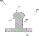
FIG. 11 illustrates a cross-sectional view of a coupler coupled to a glove according to one or more embodiments described herein;
fig. 12 illustrates a perspective view of a coupler according to one or more embodiments described herein;
fig. 13 illustrates a cross-sectional view of a coupler according to one or more embodiments described herein;
FIG. 14 illustrates a perspective view of a mobile scanning device in accordance with one or more embodiments described herein;
FIG. 15 illustrates an exploded view of a snap (snap button) according to one or more embodiments described herein;
FIG. 16 illustrates a cross-sectional view of a snap fastener in accordance with one or more embodiments described herein;
FIG. 17 illustrates another cross-sectional view of a snap fastener in accordance with one or more embodiments described herein;
FIG. 18 illustrates yet another cross-sectional view of a snap fastener in accordance with one or more embodiments described herein;
19A and 19B illustrate a back view of a glove according to one or more embodiments described herein;
20A, 20B, 20C, and 20D illustrate example gestures according to one or more embodiments described herein;
FIG. 21 illustrates a block diagram of a mobile scanning device in accordance with one or more embodiments described herein;
FIG. 22 illustrates an example electronic circuit of a first trigger circuit in accordance with one or more embodiments described herein;
FIG. 23 illustrates an equivalent electronic circuit of the first trigger circuit when the glove is wet in accordance with one or more embodiments described herein;
FIG. 24 illustrates an electronic circuit of a first trigger circuit in accordance with one or more embodiments described herein;
25A and 25B illustrate top views of gloves according to one or more embodiments described herein;
FIG. 26 illustrates a flow diagram of a method for operating a mobile scanning device in accordance with one or more embodiments described herein;
FIG. 27 illustrates a flow diagram for operating a mobile scanning device in a gesture-linked mode in accordance with one or more embodiments described herein;
FIG. 28 illustrates a flow diagram of a method for identifying the type of gesture performed by a worker in accordance with one or more embodiments described herein;
FIG. 29 illustrates another flow diagram of a method for identifying the type of gesture performed by a worker in accordance with one or more embodiments described herein; and
fig. 30 illustrates a flow diagram of a method for operating a mobile scanning device in an operational mode according to one or more embodiments described herein.
Detailed Description
Some embodiments of the present disclosure will now be described more fully hereinafter with reference to the accompanying drawings, in which some, but not all embodiments of the disclosure are shown. Indeed, these disclosures may be embodied in many different forms and should not be construed as limited to the embodiments set forth herein; rather, these embodiments are provided so that this disclosure will satisfy applicable legal requirements. Like reference numerals refer to like elements throughout. The terminology used in this patent is not meant to be limited to the extent of the devices or portions thereof described herein, but rather may be attached or utilized in other orientations.
The term "comprising" means including, but not limited to, and should be interpreted in the manner in which it is commonly used in the context of a patent. Use of broader terms such as "including", "comprising" and "having" should be understood to provide support for narrower terms such as "consisting of … …", "consisting essentially of … …", and "consisting essentially of … …".
The phrases "in one embodiment," "according to one embodiment," and the like generally mean that a particular feature, structure, or characteristic following the phrase may be included in at least one embodiment of the present disclosure, and may be included in more than one embodiment of the present disclosure (importantly, the phrases do not necessarily refer to the same embodiment).
The word "exemplary" is used herein to mean "serving as an example, instance, or illustration. Any implementation described herein as "exemplary" is not necessarily to be construed as preferred or advantageous over other implementations.
If the specification states a component or feature "may", "can", "could", "should", "will", "preferably", "possibly", "generally", "optionally", "for example", "often", or "may" (or other such language) be included or have a stated characteristic, that particular component or feature is not necessarily included or has the stated characteristic. Such components or features may optionally be included in some embodiments, or may not be included.
The phrase "mobile scanning device" corresponds to an electronic device that may be capable of detecting/receiving encoded data from a data source (such as, but not limited to, a machine-readable code, a radio frequency identification tag, a bluetooth tag, etc.). Further, the mobile scanning device may be configured to decode the encoded data. Some examples of mobile scanning devices may include, but are not limited to, bar code scanning devices, portable RFID readers, portable printers, and the like.
In work environments such as warehouses and retail stores, workers may have to wander around the facility to perform various operations. For example, a worker may have to move around a facility to scan one or more machine-readable codes to keep track of items present in a warehouse. In some examples, the worker may scan the machine-readable code using a mobile scanning device, such as a barcode scanner. Typically, the mobile scanning device occupies one hand of the worker, and thus, the worker is left with only one hand to perform other operations, such as holding an object to be scanned. Such scenarios may lead to unexpected situations and may compromise the overall efficiency of worker operations in a work environment.
The example embodiments described herein illustrate a knitted glove that, in some example embodiments, is seamlessly knitted using 3D knitting techniques. In an example embodiment, the glove includes a front portion and a back portion. The front portion corresponds to a portion of the glove that represents a palm side of the worker's hand (e.g., a ventral side of the worker's hand). Further, the rear portion corresponds to a portion of the glove that represents a rear side (e.g., back side) of the worker's hand.
Both the front portion of the glove and the back portion of the glove include an inner surface and an outer surface. In some examples, when a worker inserts a hand into a glove, the inner surfaces of both the front portion of the glove and the back portion of the glove contact the worker's hand. Further, in some examples, the exterior surfaces of both the front portion of the glove and the back portion of the glove are exposed to the ambient environment surrounding the glove. Further, the front portion of the glove and the rear portion of the glove may be divided into regions based on regions of the hand respectively in contact with them. Examples of such regions include, but are not limited to, a palm region and a plurality of finger regions. The palm region of the glove is configured to receive a palm region of a hand of a worker, and the plurality of finger regions are configured to receive fingers. The palm region of the hand forms the palm.
During the knitting of the glove, a first conductive pad is knitted at the front of the glove using conductive yarn (yarn). In some examples, the first conductive pad is woven on a distal portion of the first finger region. Similarly, a second conductive pad is knitted on the back of the glove on the second finger region. In an example embodiment, the second finger region is a different region than the first finger region. For example, the first finger region may be configured to receive a thumb and the second finger region may be configured to receive a middle finger of a worker's hand. In other examples, the first region may be configured to receive a forefinger or an index finger, while the second finger region may be configured to receive a ring finger.
The glove may also include a plurality of first through-holes configured to receive the plurality of couplers. One or more of the plurality of couplers is in electrical communication with at least one of the first conductive pad and/or the second conductive pad. Further, the plurality of couplers enable the mobile scanning device to be attached on the back of the glove. For example, the mobile scanning device may be configured to be mounted on a first through-hole on a palm area in the back of the glove via the plurality of couplers. Upon attaching the mobile scanning device to the glove, the mobile scanning device is in electrical communication with the first conductive pad and the second conductive pad through one or more of the plurality of couplers such that, in some examples, the mobile scanning device is triggered when the first conductive pad contacts the second conductive pad.
In some example embodiments, gloves may be wet due to the work environment in which the worker operates. For example, gloves may be wet from perspiration in the worker's hands. When the glove is wet, the first and second conductive pads may become electrically coupled or may be in electrical communication with each other without the worker explicitly causing the two conductive pads (the first and second conductive pads) to come into contact. This can cause the mobile scanning device to trigger erroneously. To avoid false triggering of the mobile scanning device, in some examples, the mobile scanning device includes trigger circuitry that prevents such false triggering of the mobile scanning device.
Fig. 1 illustrates an example assembly 100 of a mobile scanning device 102 mounted on a glove 104 according to one or more embodiments described herein.
In some examples herein, the mobile scanning device 102 takes the form of a barcode scanning device. Alternatively or additionally, the mobile scanning device 102 may correspond to other devices that may be mounted on the glove 104, such as portable RFID readers, mobile printers, mobile devices such as telephones, smart devices, watches, cameras, recording devices, and so forth.
In an example embodiment, the mobile scanning device 102 has a housing 106, the housing 106 having a first end portion 108, a second end portion 110, and a body portion 112. The body portion 112 extends between the first end 108 and the second end 110. In an example embodiment, the first end 108 defines a window 114, the window 114 configured to receive an image capture assembly 116. In an example embodiment, the image capture assembly 116 may be configured to capture an image or scan an object. The image capture assembly 116 may include an illumination assembly to illuminate the field of view of the imaging capture assembly. The illumination assembly may, for example, comprise an illumination source, an illumination optics assembly for directing light from the illumination source into the direction of the field of view, such as one or more lenses, a diffusing screen, an optical wedge, a mirror, or a combination of such elements. For example, if an image of an object is to be captured, the lighting assembly may be configured to direct light onto the object. Some examples of illumination sources may include, for example, lasers or Light Emitting Diodes (LEDs), such as white LEDs or red LEDs. In addition, the image capture assembly 116 comprises an imaging assembly, which may further comprise an image sensor (such as a color or monochrome 1D or 2D CCD, CMOS, NMOS, PMOS, CID, or CMD solid state image sensor) and imaging optics assembly for receiving and focusing incident light (from the ambient environment) onto the image sensor.
In some examples, the scope of the present disclosure is not limited to the first end 108 defining the window 114 configured to receive the image capture assembly 116. Indeed, any other assembly may be received at the first end 108 depending on the type of mobile scanning device 102. For example, where the mobile scanning device 102 corresponds to an RFID reader, the first end 108 may be configured to receive an RF antenna, which may be configured to receive RF signals from RFID tags. Similarly, other applications are contemplated.
In the exemplary embodiment, body portion 112 has a top surface 118 and a bottom surface 120. In an example embodiment, the bottom surface 120 is configured to receive an adapter module 122 that facilitates mounting of the mobile scanning device 102 on the glove 104. The structure of glove 104 is described in connection with fig. 3, 4, 5, and 6.
Fig. 2 illustrates an exploded view 200 of the assembly of mobile scanning device 102 and glove 104, according to one or more embodiments described herein. Referring to exploded view 200, glove 104 includes a rear portion 202 and a front portion 204. In some embodiments, the front portion 204 of the glove 104 corresponds to a portion of the glove 104 that represents a palm side of the hand of the worker (e.g., a ventral side of the hand of the worker). Further, the rear portion 202 corresponds to a portion of the glove 104 that represents a rear side (e.g., back side) of the worker's hand. In an example embodiment, when a worker moving the scanning device 102 inserts her hand into the glove 104, the ventral side of the hand contacts an inner surface (not shown) of the front portion 204 of the glove 104. In addition, the back side of the hand contacts the inner surface (not shown) of the back portion 202 of the glove 104.
In some examples, glove 104 includes a first end 201 and a second end 203. When a worker inserts a hand into the glove 104, the first end 201 is located near the wrist of the worker's hand. Further, the second end 203 is located away from the first end 201. Further, the glove 104 includes a palm area 206 and a plurality of finger areas 208. In some example embodiments, palm region 206 extends from first end 201 of glove 104 to a plurality of finger regions 208. In an example embodiment, the palm region 206 is also configured to receive the palm region of the worker's hand as the worker inserts the hand into the glove 104. In some examples, the palm region of the worker's hand corresponds to a palm of a hand.
A plurality of finger regions 208 extend outwardly from palm region 206 of glove 104 to second end 203. Further, the plurality of finger regions 208 are configured to receive fingers on a hand of a worker.
The palm region 206 on the rear portion 202 of the glove 104 includes a plurality of first through-holes 209 that extend from an outer surface 210 of the rear portion 202 of the glove 104 to an inner surface (not shown) of the rear portion 202 of the glove 104. The plurality of first vias 209 are configured to receive a plurality of couplers 212. The structure of the plurality of couplers 212 is described in conjunction with fig. 10, 11, 12, and 13.
In an example embodiment, the palm area 206 on the back portion 202 of the glove 104 is also configured to receive a pad 214 on the outer surface 210. In some exemplary embodiments, pad 214 is sewn to outer surface 210 of palm area 206 in such a manner that second plurality of through holes 211 on pad 214 are aligned with first plurality of through holes 209. In an example embodiment, the plurality of couplers 212 extend through the plurality of first vias 209 into the plurality of second vias 211. The structure of the pad 214 is further described in conjunction with fig. 8 and 9. The plurality of couplers 212 also facilitate coupling of the mobile scanning device 102 on a pad 214. The coupling of the mobile scanning device 102 on the pad 214 is described in connection with fig. 14, 15, 16, 17 and 18.
Fig. 3 and 4 illustrate a front view 300 and a rear view 400 of glove 104 according to one or more embodiments described herein. Referring to front view 300, front portion 204 of glove 104 has an outer surface 301. Each of the plurality of finger regions includes a distal portion 302, a proximal portion 301, and an intermediate portion 303. In some exemplary embodiments, proximal portion 301 is proximate to palm region 206 of glove 104. The intermediate portion 303 begins at the distal end of the proximal portion 301 and ends at the proximal end of the distal portion 302. Distal portion 302 begins at the distal end of intermediate portion 303 and extends to the end of the finger region.
In some example embodiments, a distal end 302 of a first finger region 208a of the plurality of finger regions 208 has a first conductive pad 304. For example, a thumb region 305 of the plurality of finger regions 208 includes a distal portion 302, which further includes a first conductive pad 304. Thumb area 305 is configured to receive the thumb on the hand of the worker. In the exemplary embodiment, first conductive pad 304 is formed by weaving conductive yarns on an outer surface 307 of front portion 204.
In an example, the conductive yarn corresponds to a filament capable of transmitting an electrical signal. Some examples of conductive yarns may include, but are not limited to: silver coated polyethylene, silver coated nylon, and the like. In an exemplary embodiment, the first conductive pad 304 is woven on the front portion 204 of the glove 104 and does not extend to the back portion 202 of the glove 104.
Additionally or alternatively, glove 104 may include an abrasive coating 306 disposed on front portion 204 of glove 104 (see front view 300). The abrasive coating 306 on the glove 104 increases the coefficient of friction of the glove 104, thereby reducing slippage of the object held by the worker wearing the glove 104. In an example embodiment, the abrasive coating 306 may be formed from the group including polyurethane, nitrile latex, natural latex, polyvinyl chloride (PVC), polyvinyl acetate (PVA), neoprene (polychloroprene), and rubber. In some examples, abrasive coating 306 may be a multi-layer coating including two or more of polyurethane, nitrile latex, natural latex, polyvinyl chloride (PVC), polyvinyl acetate (PVA), neoprene (polychloroprene), and rubber. In an example embodiment, the thickness of the abrasive coating is such that a portion of the conductive yarn (woven to form the first conductive pad 304) extends out from the abrasive coating 306. Thus, the conductivity of the first conductive pad 304 is not affected by the abrasive coating 306, as further illustrated in fig. 7. In an exemplary embodiment, the abrasive coating 306 on the glove 104 has a thickness of at most 0.6 mm. Additionally or alternatively, an abrasive coating may be provided on the back portion 202 of the glove 104.
Referring to rear view 400, rear portion 202 of glove 104 has an outer surface 210, outer surface 210 in some examples extending along the length of glove 104. A second conductive pad 402 is woven on the distal end 302 of a second finger region 404 of the plurality of finger regions 208. In the exemplary embodiment, second conductive pad 402 is woven using conductive yarns on outer surface 210 of rear portion 202.
In some examples, the second finger region 404 is different from the first finger region 208 a. For example, the second finger region 404 represents the middle finger region 404, and the first finger region 208a represents the thumb region 305. In an example embodiment, second conductive pad 402 is woven on back portion 202 of glove 104 and does not extend to front portion 204 of glove 104. That is, each conductive pad is configured on an opposite side of the glove.
An outer surface 210 of rear portion 202 defines a first plurality of through-holes 209 in palm region 206 of glove 104. As previously discussed, the plurality of first vias 209 are configured to receive a plurality of couplers 212, as further described in connection with fig. 10-13.
Fig. 5 and 6 illustrate a front view 500 and a rear view 600 of an inside-out glove 104 according to one or more embodiments described herein.
Referring to front view 500, it can be seen that front portion 204 of glove 104 has an interior surface 502. Further, the front portion 204 includes a first portion 504 of the first conductive path that is woven on the inner surface 502 of the front portion 204. Further, a first portion 504 of the first conductive path extends from the first conductive pad 304 (woven on the outer surface 307 of the front portion 204) to the rear portion 202 of the sleeve 104. In an example embodiment, the first portion 504 of the first conductive path is woven using conductive yarns.
Referring to rear view 600, it can be seen that rear portion 202 of glove 104 has an interior surface 602. Further, the rear portion 202 includes a second portion 604 of the first conduction path that is woven on the inner surface 602 of the rear portion 202. In an example embodiment, first portion of first conductive path 504 and second portion of first conductive path 604 are seamlessly woven together to form first conductive path 601 extending from first conductive pad 304 to first conductive area 606 such that first conductive area 606 is in electrical communication with first conductive pad 304 (formed on outer surface 307 of front portion 204 of glove 104). In some examples, the first conductive region 606 is woven on a perimeter of a first via 209a of the plurality of first vias 209.
Referring to the rear view 600, a second conductive path 608 is woven on an inner surface 602 of the rear portion 202 of the glove 104. In an example embodiment, the second conductive path 608 electrically couples and/or otherwise causes the second conductive pad 402 to be in electrical communication with a second conductive region 610 woven around a perimeter of a first via 209b of the plurality of first vias 209. In an example embodiment, the second conductive region 610 is knitted on the inner surface 602 of the back portion 202 of the glove 104. In an example embodiment, the second conductive region 610 and the second conductive path 608 are woven using conductive yarns.
In an example embodiment, the glove 104 is manufactured using one or more known 3D knitting techniques. In some examples, glove 104 may thus be manufactured as a single piece. In the exemplary embodiment and during manufacture of glove 104, various conductive and non-conductive yarns are woven together to form first conductive pad 304, second conductive pad 402, first conductive path 601 (formed by the combination of first portion of first conductive path 504 and second portion of first conductive path 604), and second conductive path 608. Further, the conductive yarns and the non-conductive yarns are woven in a manner such that the first conductive path and the second conductive path 608 are formed on the inner surface 502 of the front portion 204 of the glove 104 and the inner surface 602 of the back portion 202 of the glove 104, respectively. Additionally, the conductive yarns and the non-conductive yarns are knitted in such a manner that the first conductive pad 304 and the second conductive pad 402 are formed on the outer surface 307 of the front portion 204 of the glove 104 and the outer surface 210 of the back portion 202 of the glove 104, respectively.
Fig. 7 illustrates an exploded view 700 of the first conductive pad 304 according to one or more embodiments described herein. Referring to exploded view 700, first conductive pad 304 includes braided conductive yarn 702 and abrasive coating 306. It can be observed that the braided conductive yarn 702 extends out of the abrasive coating 306 and is thus exposed to the ambient environment surrounding the glove 104. Similarly, the conductive yarns that are woven to form second conductive pad 402 are also exposed to the ambient environment surrounding glove 104.
In an example embodiment, when the worker (e.g., wearing the glove 104) brings the first conductive pad 304 into contact with the second conductive pad 402 or into contact with the second conductive pad 402, the first conductive region 606 (e.g., electrically coupled with the first conductive pad 304) becomes electrically coupled or in electrical communication with the second conductive region 610 (e.g., electrically coupled with the second conductive pad 402).
Fig. 8 and 9 illustrate perspective views 800 and 900 of the pad 214 according to one or more embodiments described herein.
Referring to perspective view 800, pad 214 may include an outer shell 802 and a liner 804. The housing 802 is constructed of a non-conductive material such as, but not limited to, plastic. The housing 802 includes a top end portion 806, a bottom end portion 808, and a body portion 810.
The top portion 806 of the pad 214 is configured to receive the mobile scanning device 102. In an example embodiment, the tip portion 806 has a top surface 812 that substantially corresponds to a rectangular surface. In some embodiments, when pad 214 is coupled with glove 104, the length of top surface 812 is aligned with longitudinal axis 216 of glove 104. In an example embodiment, the top surface 812 of the pad 214 defines a plurality of second through-holes 211 extending from the top surface 812 to the bottom surface 902 (see fig. 9) of the tip portion 806.
The body portion 810 extends between the top end portion 806 and the bottom end portion 808. In the exemplary embodiment, body portion 810 extends non-uniformly between top end portion 806 and bottom end portion 808. For example, the body portion 810 extends non-uniformly along the width of the tip portion 806, such that the length of the body portion 810 varies along the width of the tip portion 806. In some embodiments, the varying length of the body portion 810 along the width of the tip portion 806 defines the shape of the bottom end portion 808 along the width of the tip portion 806. For example, the length of the body portion 810 varies in such a way that the bottom end portion 808 has an arcuate shape (depicted by 813) along the width of the pad 214. In some embodiments, the arcuate shape 813 of the bottom end portion 808 allows the pad 214 to be positioned in an ergonomic manner above the worker's hand when the hand is inserted into the glove 104. In the exemplary embodiment, the body portion 810 extends uniformly along the length of the tip portion 806 between the tip portion 806 and the bottom portion 808.
The liner 804 is coupled to the bottom end portion 808 of the outer shell 802 around the perimeter of the bottom end portion 808. In the exemplary embodiment, liner 804 extends outward from a bottom end portion 808 of outer shell 802. In some embodiments, liner 804 is constructed of a soft and flexible material, such as, but not limited to, rubber. In an exemplary embodiment, the use of a soft and flexible material for liner 804 further improves the ergonomics of cushion 214. For example, the sharp edge of the bottom end portion 808 of the housing 802 has much less impact on the worker's hand due to the presence of the rubber than a scenario in which the pad 214 includes only the housing 802.
Referring to the perspective view 900, a bottom surface 902 of the top portion 806 (of the housing 802) defines a plurality of second through-holes 211. As discussed, the plurality of second vias 211 extend from the top surface 812 to the bottom surface 902. In some embodiments, the plurality of second vias 211 includes a first set of second vias 814a and a second set of second vias 814 b. A first set of second through-holes 814a are defined along the length of the top portion 806 of the housing 802. Further, a first set of second through holes 814a is defined proximate to a first edge 816 of the tip portion 806 and distal to a second edge 818 of the tip portion 806. Similarly, a second set of second through holes 814b is defined proximate to a second edge 818 of the tip portion 806 and distal to the first edge 816 of the tip portion 806.
In some embodiments, the distance between any two adjacent second through holes in the first set of second through holes 814a is the same. Similarly, the distance between any two adjacent second through holes in the second set of second through holes 814b is the same.
In some embodiments, the scope of the present disclosure is not limited to having six second through holes in the plurality of second through holes 211 as depicted in fig. 8 and 9. In alternative embodiments, the pad 214 may have any number of through holes in the plurality of second through holes 211.
In an exemplary embodiment, to couple pad 214 to glove 104, pad 214 is first placed on outer surface 210 of back portion 202 of glove 104 in a manner such that a plurality of second through-holes 211 defined in pad 214 are aligned with a plurality of first through-holes 209 defined in palm region 206 of back portion 202 of glove 104. Thereafter, the liner 804 is sewn to the palm region 206. In an example embodiment, prior to stitching pad 214 to glove 104, first plurality of vias 209 receive plurality of couplers 212 as follows: such that the plurality of couplers 212 (received in the plurality of first through holes 209) are received in the plurality of second through holes 211 in the pad 214 when the pad 214 is sewn on the palm area 206. The structure of the plurality of couplers 212 is described herein in connection with fig. 10-13.
Fig. 10 illustrates an exploded view 1000 of a coupler 212a of the plurality of couplers 212 according to one or more embodiments described herein. The coupler 212a includes a first conductive connector 1002 and a second conductive connector 1004.
The first conductive connector 1002 includes a base portion 1006 and a cap portion 1008. The legs 1010 connect the base 1006 with the cap 1008. In the exemplary embodiment, base 1006 corresponds to a circular plate having a defined thickness (depicted by 1012). The base 1006 has a bottom surface 1014 and a top surface 1016. The leg 1010 extends from the top surface 1016 to the cap 1008. Cap 1008 also corresponds to a circular plate having a defined thickness (depicted by 1018). In the exemplary embodiment, a diameter of cap 1008 is smaller as compared to a diameter of base 1006. In addition, the cap 1008 has a top surface 1020 and a bottom surface 1022. In the exemplary embodiment, the legs 1010 extend from the bottom surface 1022 of the cap portion 1008 to the top surface 1016 of the base portion 1006. In an example embodiment, the first conductive connector 1002 is configured to be received in a first via 209a of one of the plurality of first vias 209, as further illustrated in connection with fig. 11.
The second conductive connector 1004 has a first end 1024, a second end 1026, a base 1028, and a cylindrical portion 1030. In the exemplary embodiment, base 1028 corresponds to a circular plate extending between first end 1024 and cylindrical portion 1030. The cylindrical portion 1030 extends from the base 1028 to the second end 1026.
In the exemplary embodiment, base 1028 has a bottom surface 1032 and a top surface 1034. In the exemplary embodiment, cylindrical portion 1030 extends from a top surface 1034 of base portion 1028 to second end 1026. In an exemplary embodiment, the diameter of the base portion 1028 is greater than the diameter of the cylindrical portion 1030 such that a step 1036 is formed at the junction 1038 between the base portion 1028 and the cylindrical portion 1030.
In the exemplary embodiment, cylindrical portion 1030 has a top end portion 1040, a bottom end portion 1042, and a body portion 1044. A body portion 1044 extends between the top end portion 1040 and the bottom end portion 1042.
In an exemplary embodiment, the second conductive connector 1004 further includes a bore 1046, the bore 1046 extending from a top end portion 1040 of the cylindrical portion 1030 to a bottom surface 1032 of the base portion 1028. In an example embodiment, when coupler 212a is coupled to glove 104, bottom surface 1032 of base 1028 abuts outer surface 210 of rear portion 202 of glove 104. Further, when coupler 212a is coupled to glove 104, bore 1046 is aligned with first through-hole 209 a. Further, the bore 1046 of the second conductive connector 1004 is configured to receive the cap 1008 of the first conductive connector 1002. More specifically, the second conductive connector 1004 is configured to receive the cap portion 1008 from the base portion 1028 into the bore 1046.
In the exemplary embodiment, bore 1046 has a wall 1050 defined by an inner surface 1052 of second conductive connector 1004. The inner surface 1052 of the second conductive connector 1004 defines one or more slot pairs 1054a and 1054b such that the slots of the slot pairs (e.g., slot pair 1054 a) are defined opposite one another along a horizontal axis a-a' (depicted by 1056). Further, a slot pair (e.g., slot pair 1054 a) is defined at an offset from the central longitudinal axis B-B' (depicted by 1058) of the second conductive connector 1004. Similarly, slot pair 1054b is defined on inner surface 1052 of bore 1046. In the exemplary embodiment, slot pair 1054b and slot pair 1054a are defined in the same horizontal plane C-C' (depicted by 1060). In addition, slot pair 1054b and slot pair 1054a are defined on the inner surface 1052 of the second conductive connector 1004 proximate the second end 1026 of the second conductive connector 1004 and distal the first end 1024 of the second conductive connector 1004. Further, each of the one or more slot pairs 1054a and 1054b is configured to receive an engagement member 1055. In some example embodiments, the engagement members 1055 may correspond to wires received in a slot pair (e.g., slot pair 1054 a) of the one or more slot pairs 1054a and 1054 b.
In some embodiments, the scope of the present disclosure is not limited to having the one or more slot pairs 1054a and 1054b (defined in bore 1046) to receive the engagement member 1055. In an alternative embodiment, the inner surface 1052 of the bore 1046 may define an annular protrusion proximate the second end 1026. The annular protrusion may correspond to the engagement member 1055.
To couple coupler 212a to glove 104, second conductive connector 1004 is placed on outer surface 210 of back portion 202 of glove 104 in a manner such that bore 1046 is aligned with first through-hole 209a of the plurality of first through-holes 209. Thereafter, the first conductive connector 1002 is received in the first through hole 209a from the inner surface 502 of the glove 104 in a manner such that the cap portion 1008 of the first conductive connector 1002 passes through the first through hole 209a into the bore 1046. In addition, cap 1008 is slip fit (snap fit) into bore 1046.
Fig. 11 illustrates a cross-sectional view 1100 of coupler 212a coupled to glove 104, according to one or more embodiments described herein. The cross-sectional view 1100 has been described in conjunction with fig. 10.
Cross-sectional view 1100 depicts top surface 1016 of base 1006 of first conductive connector 1002 abutting inner surface 502 of palm region 206 of back portion 202 of glove 104. In some embodiments, where the first conductive region 606 is woven around the perimeter of the first via 209a, the top surface 1016 of the base 1006 (of the first conductive connector 1002) abuts the first conductive region 606. Thus, in such embodiments, the first conductive connector 1002 is electrically coupled to or in electrical communication with the first conductive region 606. Similarly, in some example embodiments, where the second conductive region 610 is woven around the perimeter of the first via 209a, the top surface 1016 of the base 1006 (of the first conductive connector 1002) abuts the second conductive region 610.
Further, referring to cross-sectional view 1100, a bottom surface 1032 of base 1028 of second conductive connector 1004 abuts outer surface 210 of glove 104 such that bore 1046 is aligned with first throughbore 209a on glove 104.
As discussed, the inner surface 1052 of the second conductive connector 1004 corresponds to a wall of a bore 1046 extending between the first and second ends 1024, 1026 of the second conductive connector 1004. In the exemplary embodiment, an inner surface 1052 of bore 1046 defines a first bore portion 1102 and a second bore portion 1104. The first bore portion 1102 extends from the bottom surface 1032 of the base 1028 portion to a junction 1106 between the first bore portion 1102 and the second bore portion 1104. Further, the second bore portion 1104 extends from the junction 1106 to a second end 1026 of the second conductive connector 1004. In the exemplary embodiment, a diameter of first bore portion 1102 is less than a diameter of second bore portion 1104, thereby defining a step 1108 at a junction 1106.
As previously discussed, the cap 1008 of the first conductive connector 1002 is received in the bore 1046 of the second conductive connector 1004. More specifically, as can be seen in the cross-sectional view 1100, the cap 1008 is in sliding engagement with a step 1108 defined by an inner surface 1052 of the second conductive connector 1004. Since both the first conductive connector 1002 and the second conductive connector 1004 are composed of a conductive material, when the cap portion 1008 of the first conductive connector 1002 is slide-fit in the bore 1046, the second conductive connector 1004 becomes electrically coupled with the first conductive connector 1002. Thus, the second conductive connector 1004 can be in electrical communication with the first conductive connector.
In some embodiments, the scope of the present disclosure is not limited to the cap portion 1008 of the first conductive connector 1002 being slip-fit into the bore 1046 of the second conductive connector 1004. In alternative embodiments, the cap 1008 of the first conductive connector 1002 may be riveted in the bore 1046 of the second conductive connector 1004 without departing from the scope of the present disclosure.
Further, in an example scenario where the base 1006 of the first conductive connector 1002 abuts the first conductive region 606 or the second conductive region 610, the second conductive connector 1004 becomes electrically coupled or in electrical communication with the first conductive region 606 or the second conductive region 610. Further, since the first conductive region 606 is electrically coupled or in electrical communication with the first conductive pad 304 and the second conductive connector 1004, the first conductive pad 304 is electrically coupled to the second conductive connector 1004.
In some examples, the plurality of couplers 212 may be coupled to the plurality of first vias 209, as discussed above in connection with fig. 10 and 11. For example, the first via 209a and the first via 209b may receive the couplers 212a and 212b, respectively. As previously discussed, the first via 209a and the first via 209b have a first conductive region 606 and a second conductive region 610, and thus, upon receiving the couplers 212a and 212b, respectively, the couplers 212a and 212b become electrically coupled or in electrical communication with the first conductive pad 304 and the second conductive pad 402, respectively.
Fig. 12 and 13 illustrate perspective 1200 and cross-sectional 1300 views of a coupler 212a according to one or more embodiments described herein.
Referring to perspective view 1200, coupler 212a includes a third conductive connector 1202 having a first end 1204 and a second end 1206. The body portion 1205 of the third conductive connector 1202 extends along a central longitudinal axis D-D' (depicted by 1207) between the first end 1204 and the second end 1206. The top surface 1208 of the third conductive connector 1202 defines a cavity 1210 about a central longitudinal axis D-D' (depicted by 1207). The cavity 1210 has an inner surface 1212.
In addition, the top surface 1208 defines a plurality of third through-holes 1214 that surround the cavity 1210. A plurality of third vias 1214 extend from the second end 1206 to the bottom surface 1216 of the third conductive connector 1202. In the exemplary embodiment, each third via of plurality of third vias 1214 is equidistant from central longitudinal axis D-D' (depicted by 1207). The plurality of third through holes 1214 includes a first pair of third through holes 1214a and a second pair of third through holes 1214 b. The third through-holes of the first pair of third through-holes 1214a are opposite one another on an axis E-E' along the diameter (depicted by 1216), such that a lumen 1210 is defined between the third through-holes 1214a-1 and 1214a-2 of the first pair of third through-holes 1214 a. Similarly, the third through-holes of the second pair of third through-holes 1214b are also opposite one another in the diametric axis F-F' (depicted by 1218), such that a lumen 1210 is defined between the third through-holes 1214b-1 and 1214 b-2. In the exemplary embodiment, axis E-E 'along the diameter (depicted by 1216) and axis F-F' along the diameter (depicted by 1218) are orthogonal to one another.
Similar to the second conductive connector 1004, the third conductive connector 1202 may include one or more slot pairs 1054a and 1054b defined on the inner surface 1212 of the cavity. Further, each of the one or more slot pairs 1054a and 1054b is defined proximate the second end 1206 and is configured to receive an engagement member 1055. In an example embodiment, as discussed, the engagement members correspond to wires received in a slot pair (e.g., 1054 a) of the one or more slot pairs 1054a and 1054 b.
Referring to cross-sectional view 1300, when coupler 212a is coupled to glove 104, bottom surface 1216 of third conductive connector 1202 abuts outer surface 210 of glove 104. In addition, a plurality of third through holes 1214 are utilized to couple coupler 212a to outer surface 210 of glove 104.
With further reference to cross-sectional view 1300, an inner surface 1212 of cavity 1210 defines a wall of cavity 1210. In addition, the chamber 1210 has a bottom 1302, the bottom 1302 being substantially orthogonal to the walls of the chamber 1210. A conductive biasing member 1304 extends from the base 1302 toward the second end 1206. In an example embodiment, the conductive biasing member 1304 is electrically coupled or in electrical communication with the bottom surface 1216 of the third conductive connector 1202. In an example embodiment, the biasing member corresponds to a spring member that compresses when a force is applied thereto and returns to an original state when the force is removed.
In examples where the coupler 212a having the third conductive connector 1202 is coupled to the glove 104, the glove 104 may not have the plurality of first through holes 209 defined on the palm region 206 of the glove 104. Further, in this scenario, first conductive region 606 and second conductive region 610 are formed on outer surface 210 of glove 104. In some embodiments, when the coupler 212a is coupled to the glove 104 such that the bottom surface 1216 of the third conductive connector 1202 abuts the first conductive region 606, the conductive biasing member 1304 becomes electrically coupled or in electrical communication with the first conductive region 606. Similarly, when the coupler 212a is coupled to the glove 104 such that the bottom surface 1216 of the third conductive connector 1202 abuts the second conductive region 610, the conductive biasing member 1304 becomes electrically coupled or in electrical communication with the second conductive region 610.
As previously discussed, when the pad 214 is sewn onto the back portion 202 of the glove 104, the plurality of couplers 212 extend into the plurality of second through holes 211 defined in the pad 214. In an example embodiment, the plurality of couplers 212 extend to the top surface 812 of the pad 214. The plurality of couplers 212 facilitate coupling of the adaptor module 122 of the mobile scanning device 102 on the pad 214. The structure of the mobile scanning device 102 with the adaptor module 122 will now be discussed in connection with fig. 14.
Fig. 14 illustrates a perspective view 1400 of the mobile scanning device 102 in accordance with one or more embodiments described herein. As previously discussed, the mobile scanning device 102 has a bottom surface 120 configured to receive an adaptor module 122. The adaptor module 122 has a bottom surface 1402 that defines a plurality of chambers 1404. The plurality of cavities 1404 are configured to receive a plurality of snaps 1406. In an example embodiment, the plurality of snaps 1406 are configured to be received in the plurality of couplers 212 to couple the mobile scanning device 102 to the pad 214. The structure of the plurality of snap fasteners 1406 is described in connection with fig. 15, 16 and 17.
FIG. 15 illustrates an exploded view 1500 of a snap 1406a of the plurality of snap fasteners 1406 according to one or more embodiments described herein.
The snap 1406a includes a fourth conductive connector 1502 and a fifth conductive connector 1504. In an example embodiment, the fourth conductive connector 1502 and the fifth conductive connector 1504 are riveted together to form a snap 1406a, as described later in connection with fig. 16. In an alternative embodiment, the fourth conductive connector 1502 and the fifth conductive connector 1504 are threaded together to form a snap 1406a, as described later in connection with fig. 17.
The fourth conductive connector 1502 has a first end 1506 and a second end 1508. Further, the fourth conductive connector 1502 includes a base 1510, a cone 1512, and a dome 1514. Base 1510 extends between first end 1506 to cone 1512. Further, the base 1510 corresponds to a circular plate having a defined thickness. The bottom surface 1511 of the base 1510 defines a cavity 1513, the cavity 1513 extending from the first end 1506 of the fourth conductive connector 1502 into the dome portion 1514.
A conical portion 1512 extends between the base 1510 and the dome portion 1514. In some embodiments, the radius of the cone 1512 decreases as the cone 1512 extends from the base 1510 to the dome 1514. In the exemplary embodiment, a radius of a bottom 1516 of cone 1512 is less than a radius of base 1510.
In an exemplary embodiment, the dome portion 1514 may have an inverted conical shape, wherein the radius of the dome portion 1514 increases as the dome portion 1514 extends from the cone portion 1512 to the second end 1508. As the radius of the dome portion 1514 increases from the cone portion 1512 to the second end 1508, a bend (kink) 1517 is formed at the junction of the cone portion 1512 and the dome portion 1514. In some embodiments, the scope of the present disclosure is not limited to the dome 1514 having an inverted conical shape. In an alternative embodiment, the dome portion 1514 may have a spherical shape extending from the cone portion 1512 to the second end 1508 of the fourth conductive connector 1502.
In an example embodiment, the dome 1514 is configured to be received in the plurality of couplers 212. Further, the dome portion 1514 is snap-fit with an engagement member 1055 of the plurality of couplers 212 in a manner such that the engagement member 1055 is received at the bend 1517 (i.e., the junction between the dome portion 1514 and the cone portion 1512).
The fifth conductive connector 1504 includes a base portion 1518, a bulbous end portion 1520, and a body portion 1522. Similar to the base 1510 of the fourth conductive connector 1502, the base 1518 of the fifth conductive connector 1504 also corresponds to a circular plate that extends from the first end 1524 of the fifth conductive connector 1504 to the body portion 1522 of the fifth conductive connector 1504. The body portion 1522 of the fifth conductive connector 1504 extends from the base 1518 to the bulbous end 1520. Further, the bulbous end 1520 extends from the body portion 1522 to a second end 1526 of the fifth conductive connector 1504. In an example embodiment, the body portion 1522 and the bulbous end 1520 of the fifth conductive connector 1504 are configured to be received in the cavity 1513 of the fourth conductive connector 1502. In some example embodiments, the fifth conductive connector 1504 is riveted with the fourth conductive connector 1502 to form a snap 1406a, as illustrated in fig. 16.
FIG. 16 illustrates a cross-sectional view 1600 of a snap fastener 1406a according to one or more embodiments described herein. Referring to the cross-sectional view 1600, the body portion 1522 and the bulbous end 1520 of the fifth conductive connector 1504 are received in the cavity 1513. Further, as can be seen from the cross-sectional view 1600, the base 1510 of the fourth conductive connector 1502 and the base 1518 of the fifth conductive connector 1504 are attached to the adaptor module 122 of the mobile scanning device 102.
In some embodiments, the scope of the present disclosure is not limited to riveting the fourth conductive connector 1502 with the fifth conductive connector 1504 to form the snap 1406 a. In an alternative embodiment, the fourth conductive connector 1502 may be threaded together with the fifth conductive connector 1504 to form a snap 1406a, as further described in connection with fig. 17.
FIG. 17 illustrates a cross-sectional view 1700 of a snap fastener 1406a according to one or more embodiments described herein.
Referring to cross-sectional view 1700, inner surface 1702 of chamber 1513 defines a plurality of first threads 1704. Further, the outer surface 1706 of the fifth conductive connector 1504 defines a plurality of second threads 1708. More specifically, the outer surface 1706 defines a plurality of second threads on the body portion 1522 and the bulbous end 1520 of the fifth conductive connector 1504. When the fourth conductive connector 1502 is threaded with the fifth conductive connector 1504, the plurality of first threads 1704 engage the plurality of second threads 1708. The assembly of the fourth conductive connector 1502 and the fifth conductive connector 1504 form a snap 1406 a.
In yet another alternative embodiment, the snap 1406a may not include the separate fourth and fifth conductive connectors 1502, 1504. In an example embodiment, the snap fasteners 1406a may be formed as a single solid body, as further described in connection with FIG. 18.
FIG. 18 illustrates a cross-sectional view 1800 of a snap fastener 1406a according to one or more embodiments described herein. Referring to cross-sectional view 1800, snap 1406a includes a base 1510, a body portion 1804, and a dome 1514. The body portion 1804 corresponds to a cylindrical body that extends from the base 1510 to the dome 1514. Further, a bend 1517 is defined at the junction of the body portion 1804 and the dome portion 1514. As discussed, when the snap 1406a is snap-fit in the plurality of couplers 212, the engagement member 1055 is received at the bend 1517.
In an example embodiment, to couple the mobile scanning device 102 with the glove 104 on the pad 214, a plurality of snaps 1406 on the adaptor module 122 are snap-fit to the plurality of couplers 212. As previously discussed, one or more couplers (e.g., 212a and 212 b) of the plurality of couplers are electrically coupled or in electrical communication with the first conductive region 606 and the second conductive region 610, respectively. Thus, when the mobile scanning device 102 is coupled to the glove 104 by the plurality of snaps 1406, one or more of the plurality of snap-fit buttons (e.g., 1406a and 1406 b) electrically couple with the first conductive region 606 and the second conductive region 610.
In an example embodiment, one or more snap-fit buttons (e.g., 1406a and 1406 b) are also coupled to one or more components of the mobile scanning device 102. For example, one or more of the snap-fit buttons (e.g., 1406a and 1406 b) are coupled to a first trigger circuit of the mobile scanning device 102. In an example embodiment, the first trigger circuit corresponds to an electronic circuit that generates a first trigger signal that causes the mobile scanning device 102 to perform a predetermined operation. For example, upon receiving the first trigger signal, the mobile scanning device 102 triggers the image capture assembly 116 of the mobile scanning device 102 to capture an image or scan a machine-readable indicia.
In an embodiment, when a worker (e.g., using the mobile scanning device 102) touches the first conductive pad 304 (located on the front 204 of the thumb region 305 of the glove 104) with the second conductive pad 402 (located on the rear 202 of the middle finger region 404), the first conductive region 606 becomes electrically coupled or in electrical communication with the second conductive region 610. As first conductive region 606 becomes electrically coupled or in electrical communication with second conductive region 610, snap 1406a becomes electrically coupled or in electrical communication with snap 1406 b. This causes the first trigger circuit to be completed and generates the first trigger signal. The operation of the first flip-flop circuit is further described in conjunction with fig. 22, 23 and 24.
In some embodiments, the scope of the present invention is not limited to having only two conductive pads (i.e., the first conductive pad 304 and the second conductive pad 402) to control the triggering of the image capture assembly 116. In alternative embodiments, glove 104 may include more than two conductive pads for controlling the operation of other components of mobile scanning device 102. A glove 104 having more than two conductive pads is illustrated in fig. 19A and 19B.
Fig. 19A and 19B illustrate a rear view 1900A of glove 104 and a rear view 1900B of glove 104 inside-out, respectively, according to one or more embodiments described herein.
Referring to back view 1900A, a third conductive pad 1902 is woven on the second finger region 404 slightly below the second conductive pad 402. In the exemplary embodiment, third conductive pad 1902 is proximate palm region 206 of glove 104 and distal to distal end 302 on second finger region 404. In an example embodiment, the third conductive pad 1902 is similar to the second conductive pad 402. For example, both the third conductive pad 1902 and the second conductive pad 402 are woven using the same conductive yarn using one or more 3D weaving techniques.
In some embodiments, the scope of the present disclosure is not limited to having third conductive pad 1902 woven over second finger region 404 of glove 104. In alternative embodiments, third conductive pad 1902 may be woven on any of the other finger regions 208 of the plurality of finger regions 208 of glove 104. For example, the third conductive pad 1902 may be woven over the distal end 302 of the ring finger region 1904.
Referring to the back view 1900B, the third conductive path 1906 is woven such that the third conductive pad 1902 is electrically coupled or in electrical communication with the third conductive region 1908. The third conductive region 1908 is woven around the perimeter of a first via 209c of the plurality of first vias 209. As previously discussed, when the plurality of couplers 212 are coupled to the glove 104, one of the plurality of couplers 212 is electrically coupled or in electrical communication with the third conductive region 1908. For example, the coupler 212c is electrically coupled or in electrical communication with the third conductive region 1908 and the third conductive pad 1902.
In addition, when the mobile scanning device 102 is mounted on the glove 104 by way of the plurality of snaps 1406 on the adaptor module 122, the snap-fit button (e.g., snaps 1406 c) also becomes electrically coupled or in electrical communication with the third conductive region 1908 and the third conductive pad 1902. In addition, the snap 1406c is also coupled to a second trigger circuit in the mobile scanning device 102. In an example embodiment, the second trigger circuit is configured to generate a second trigger signal that causes the mobile scanning device 102 to perform a predetermined operation. In some examples, the operations performed in response to the first trigger signal are different from the operations performed in response to the second trigger signal. For example, upon receiving the second trigger signal, a display screen on the mobile scanning device 102 is activated.
When a worker (e.g., using the mobile scanning device 102) touches the first conductive pad 304 with the third conductive pad 1902, the first conductive region 606 becomes electrically coupled or in electrical communication with the third conductive region 1908. This causes the second trigger circuit to generate a second trigger signal. Similarly, glove 104 may have additional conductive pads woven on different ones of the plurality of finger regions 208. Further, in some examples, the conductive pads may be woven on the same finger area, as illustrated in fig. 19A.
In an example embodiment, to cause the first conductive pad 304 to contact the second conductive pad 402 or the third conductive pad 1902, a worker wearing gloves may have to generate a predetermined shape or gesture with the glove 104 by moving the plurality of finger regions 208 in a predetermined manner. Hereinafter, creating a predetermined shape with the glove 104 is referred to as making a gesture.
Since making a gesture with glove 104 helps cause first conductive pad 304 to come into contact with second conductive pad 402 or third conductive pad 1902 (which causes mobile scanning device 102 to perform a predetermined operation), each gesture corresponds to an operation performed by mobile scanning device 102. Some examples of such gestures are illustrated in fig. 20A and 20B.
20A and 20B illustrate example gestures 2000A and 2000B, respectively, according to one or more embodiments described herein.
Referring to example gesture 2000A, middle finger region 404 of glove 104 is curved toward front 204 of glove 104. Further, the front 204 of the thumb area 305 is in contact with the rear 202 of the middle finger area 404. Referring to example gesture 2000B, ring finger region 1904 of glove 104 curves toward front 204 of glove 104. Further, the front 204 of the thumb area 305 is in contact with the back 202 of the ring finger area 1904.
As previously discussed, each gesture performed on the glove 104 causes the mobile scanning device 102 to perform a predetermined operation. Various components of the mobile scanning device 102 that enable the mobile scanning device 102 to perform predetermined operations are further described in conjunction with fig. 21.
In some embodiments, the scope of the present disclosure is not limited to gestures corresponding to shapes that a worker may make with a glove 104 to cause the first conductive pad 304 to contact the second conductive pad 402 or the third conductive pad 1902 as illustrated in fig. 20A and 20B. In an example embodiment, the gesture may also include an action performed by the worker to cause the first conductive pad 304 to contact the second conductive pad 402 and the third conductive pad 1902 in a predetermined sequence, as further described in fig. 20C and 20D.
20C and 20D illustrate example gestures 2000C and 2000D according to one or more embodiments described herein.
Referring to fig. 20C, glove 104 has second conductive pad 402 and third conductive pad 1902 woven on middle finger region 404 of rear portion 202 of glove 104. Additionally, a third conductive pad 1902 is knitted under the second conductive pad 402 and proximate to the palm area 206 of the glove 104. To perform the gesture 2000C, the worker may slide the first conductive pad 304 (woven on the thumb region 305) over the back 202 of the middle finger region 404 from the second end 203 of the glove 104 toward the palm region 206 of the glove 104. Such action by the worker first causes the first conductive pad 304 to contact the second conductive pad 402, and subsequently causes the first conductive pad 304 to contact the third conductive pad 1902. Such a sequence (causing the first conductive pad 304 to contact the second conductive pad 402 and the third conductive pad 1902) causes the mobile scanning device 102 to perform a predetermined operation. Hereinafter, the gesture 2000C is referred to as a slide-down gesture 2000C.
In some example embodiments, referring to gesture 2000D, the worker may reverse the order in which the first conductive pad 304 is brought into contact with the second conductive pad 402 and the third conductive pad 1902. For example, the worker may slide the first conductive pad 304 (woven on the thumb region 305) over the back 202 of the middle finger region 404 from the palm region 206 of the glove 104 toward the second end 203 of the glove 104. Such action by the worker first causes the first conductive pad 304 to contact the third conductive pad 1902, and subsequently causes the first conductive pad 304 to contact the second conductive pad 402. Performing such a gesture causes the mobile scanning device 102 to perform a predetermined operation, as further described in connection with fig. 29. Hereinafter, the gesture 2000D performed by the worker is referred to as a swipe-up gesture 2000D.
Fig. 21 illustrates a block diagram of the mobile scanning device 102 in accordance with one or more embodiments described herein. In some examples, the mobile scanning device 102 includes a first triggering circuit 2102, a second triggering circuit 2104, a display screen 2106, and a control system 2108. The control system 2108 further comprises a processor 2110, a memory device 2112, a communication interface 2114 and a gesture recognition unit 2116. In an example embodiment, the first triggering circuit 2102 and the second triggering circuit 2104 are communicatively coupled to a control system 2108. In addition, the first triggering circuit 2102 and the second triggering circuit 2104 are electrically coupled to or in electrical communication with the first conductive pad 304 on the glove 104. Additionally, the first triggering circuit 2102 is electrically coupled or in electrical communication with the second conductive pad 402, and the second triggering circuit 2104 is electrically coupled or in electrical communication with a different conductive pad (such as the third conductive pad 1902) than the second conductive pad 402.
The first trigger circuit 2102 comprises suitable logic/circuitry configured to generate a first trigger signal when the first conductive pad 304 contacts the second conductive pad 402. The structure and operation of the first flip-flop circuit 2102 are described in conjunction with fig. 22 to 24. In an example embodiment, the second trigger circuit 2104 is configured to generate a second trigger signal when the first conductive pad 304 contacts the third conductive pad 1902. Further, the first and second triggering circuits 2102, 2104 are configured to transmit first and second triggering signals, respectively, to the control system 2108.
The display screen 2106 may comprise suitable logic, circuitry, interfaces, and/or code that may be operable to present a display. In an example embodiment, the display screen 2106 may be implemented by several known technologies, such as Cathode Ray Tube (CRT) based displays, Liquid Crystal Displays (LCDs), Light Emitting Diode (LED) based displays, organic LED display technologies, and Retina display technologies. In some example embodiments, the display screen 2106 may be configured to display one or more messages/notifications. Some examples of the one or more messages/notifications may include, but are not limited to, information decoded from indicia scanned by the mobile scanning device 102. In some embodiments, the display screen 2106 may include a touch panel, such as a capacitive touch panel, a thermal touch panel, and/or a resistive touch panel, which may enable a worker to provide input to the mobile scanning device 102.
The control system 2108 comprises suitable logic, circuitry, interfaces, and/or code that may be operable to control one or more operations of the mobile scanning device 102. For example, the control system 2108 can control the capture of images by the image capture assembly 116. As discussed, the control system 2108 includes a processor 2110, a memory device 2112 and a communication interface 2114.
The processor 2110 may be implemented as an apparatus comprising: one or more microprocessors with accompanying digital signal processor(s), one or more processors without an accompanying digital signal processor, one or more coprocessors, one or more multi-core processors, one or more controllers, processing circuitry, one or more computers, various other processing elements including integrated circuits such as, for example, an Application Specific Integrated Circuit (ASIC) or a Field Programmable Gate Array (FPGA), or some combination thereof. Thus, although illustrated in fig. 21 as a single controller, in embodiments, the processor 2110 may comprise a plurality of controllers and signal processing modules. Multiple controllers may be implemented on a single electronic device or may be distributed across multiple electronic devices collectively configured to function as circuitry of control system 2108. The multiple processors may be in operable communication with each other and may be collectively configured to perform one or more functionalities of the circuitry of the control system 2108 as described herein. In an example embodiment, the processor 2110 may be configured to execute instructions stored in the memory device 2112 or otherwise accessible to the processor 2110. These instructions, when executed by the processor 2110, may cause the circuitry of the control system 2108 to carry out one or more of the functionalities as described herein.
Whether configured by hardware, firmware/software methods, or by a combination thereof, the processor 2110 may include an entity capable of performing operations according to embodiments of the present disclosure when configured accordingly. Thus, for example, when the processor 2110 is implemented as an ASIC, FPGA or the like, the processor 2110 may include specially configured hardware for performing one or more of the operations described herein. Alternatively, as another example, when the processor 2110 is implemented as an executor of instructions (such as may be stored in the memory device 2112), the instructions may specifically configure the processor 2110 to perform one or more of the algorithms and operations described herein.
Accordingly, the processor 2110 as used herein may refer to a programmable microprocessor, microcomputer or multiple processor chip(s) that can be configured by software instructions (applications) to perform various functions, including the functions of the various embodiments described above. In some devices, multiple processors dedicated to wireless communication functions and one processor dedicated to running other applications may be provided. Software applications may be stored in internal memory before they are accessed and loaded into the processor. The processor may include internal memory sufficient to store the application software instructions. In many devices, the internal memory may be volatile or non-volatile memory (such as flash memory), or a mixture of both. The memory may also be located in another computing resource (e.g., to enable downloading of the computer-readable instructions over the internet or another wired or wireless connection).
The memory device 2112 may comprise suitable logic, circuitry, and/or interfaces that may be adapted to store a set of instructions that may be executed by the processor 2110 to perform predetermined operations. Some of the well known memory implementations include, but are not limited to: a hard disk, random access memory, cache memory, read-only memory (ROM), erasable programmable read-only memory (EPROM), and electrically erasable programmable read-only memory (EEPROM), flash memory, magnetic cassettes, magnetic tape, magnetic disk storage or other magnetic storage devices, compact disk read-only memory (CD-ROM), digital versatile disk read-only memory (DVD-ROM), optical disk, circuitry configured to store information, or some combination thereof. In an embodiment, the memory device 2112 may be integrated with the processor 2110 on a single chip without departing from the scope of the present disclosure.
The gesture recognition unit 2116 may comprise suitable logic, circuitry, interfaces and/or code that may be operable to receive the first trigger signal and the second trigger signal from the first trigger circuit 2102 and the second trigger circuit 2104, respectively. Further, the gesture recognition unit 2116 may be configured to recognize the type of gesture performed by the worker moving the scanning device based on receipt of the first trigger signal and the second trigger signal, as further described in fig. 28. In some examples, the gesture recognition unit 2116 may be configured to operate the mobile scanning device 102 in a gesture association mode in which the gesture recognition unit 2116 may be configured to associate the type of gesture with a predetermined operation of the mobile scanning device 102, as further described in connection with fig. 28. Further, the gesture recognition unit 2116 may be configured to operate the mobile scanning device 102 in an operational mode in which the gesture recognition unit 2116 may be configured to recognize a predetermined operation of the mobile scanning device 102 to be performed based on the recognized gesture type, as further described in fig. 29. In an example embodiment, the gesture recognition unit 2116 may be implemented using one or more technologies, such as, but not limited to, FPGA, ASIC, and the like.
Fig. 22 illustrates an example electronic circuit 2200 of a first trigger circuit 2102 in accordance with one or more embodiments described herein, which in some examples prevents false triggering if glove 104 is wet.
In an example embodiment, electronic circuit 2200 includes a comparator 2202 having a first input terminal 2204, a second input terminal 2206, a voltage input terminal 2208, a ground input terminal 2210, and an output terminal 2212. In some embodiments, the comparator 2202 may correspond to an operational amplifier (OP-AMP). In an alternative embodiment, the comparator 2202 may be implemented using a comparator IC, as described later in connection with fig. 23. Further, the electronic circuit 2200 includes a voltage source 2214 and a ground 2216. Additionally, electronic circuit 2200 depicts first conductive pad 304 coupled to ground 2216. For the purpose of description, the first input terminal 2204 of the comparator 2202 corresponds to a negative terminal, and the second input terminal 2206 of the comparator 2202 corresponds to a positive terminal.
In an example embodiment, the first input terminal 2204 of the comparator 2202 is coupled to the second conductive pad 402. Further, the first input terminal is coupled to a voltage source 2214 through a first resistive element 2218. The second input terminal 2206 is coupled to a voltage source 2214 through a second resistive element 2220. Additionally, second input terminal 2206 is coupled to ground 2216 through a third resistive element 2222. In an example embodiment, the voltage input terminal 2208 of the comparator 2202 is coupled to a voltage source 2214. Further, ground input terminal 2210 of comparator 2202 is coupled to ground 2216. In an example embodiment, output terminal 2212 is coupled to processor 2110.
In operation, when a worker (e.g., wearing glove 104) touches first conductive pad 304 with second conductive pad 402, the voltage at first input terminal 2204 has a value of 0 volts because first conductive pad 304 is grounded. On the other hand, the value of the voltage at the second input terminal 2206 is represented by:

wherein,
V in2: voltage at second input terminal 2206;
R 3: a third resistive element 2222; and
R 2: a second resistive element 2220.
Since the value of the voltage at the second input terminal 2206 (which is the positive terminal of the comparator 2202) is greater than the first input terminal 2204 (Which is the negative terminal of the comparator 2202), the value of the voltage at the output terminal 2212 is therefore Vcc. In an example embodiment, V generated at output terminal 2212ccThe voltage corresponds to the first trigger signal.
Fig. 23 illustrates an equivalent electronic circuit 2300 of the first trigger circuit 2102 when the glove 104 is wet in accordance with one or more embodiments described herein.
In an example embodiment, equivalent electronic circuit 2300 is similar to electronic circuit 2200. Additionally, the equivalent electronic circuit 2300 has a fourth resistive element 2302 coupled between the first input terminal 2204 and ground 2216. In an example embodiment, the fourth resistive element 2302 corresponds to an equivalent resistance of a wet glove.
Further, when glove 104 is wet, the value of the voltage at first input terminal 2204 is exemplified by the following equation:

wherein,
V in1: voltage at first input terminal 2204;
R 1: a first resistive element 2218; and
R 4: a fourth resistive element 2302.
In some example embodiments, as discussed, the comparator 2202 is configured to generate the first trigger signal when a value of a voltage at the first input terminal 2204 (the negative terminal of the comparator 2202) is less than a value of a voltage at the second input terminal 2206 (the positive terminal of the comparator 2202). Further, when the value of the voltage at the first input terminal 2204 (the negative terminal of the comparator 2202) is greater than the value of the voltage at the second input terminal 2206 (the positive terminal of the comparator 2202), the comparator 2202 does not generate the first trigger signal as shown by the following equation:

in an example embodiment, equation 3 may be simplified as follows:

in an example embodiment, referring to equations 3 and 4, the values of the voltages at the first and second input terminals 2204 and 2206 depend on the values of the first, second, third, and fourth resistive elements 2218, 2220, 2222, 2302. Thus, to avoid false triggering of first trigger circuit 2102 when glove 104 is wet, the values of third resistive element 2222 and second resistive element 2220 are selected such that: when the glove 104 is wet, the ratio of the third resistive element 2222 to the second resistive element 2220 remains less than the ratio of the fourth resistive element 2302 to the first resistive element 2218. In an example embodiment, the values of the third resistive element 2222 and the second resistive element 2220 are set during the manufacture of the mobile scanning device 102.
In the event that the worker intentionally touches the first conductive pad 304 with the second conductive pad 402, the value of the fourth resistive element 2302 is set to zero. Therefore, the ratio of the fourth resistive element 2302 to the first resistive element 2218 becomes zero. Therefore, the ratio of the fourth resistive element 2302 to the first resistive element 2218 becomes smaller than the ratio of the third resistive element 2222 to the second resistive element 2220. Accordingly, the value of the voltage at the first input terminal 2204 (the negative terminal of the comparator 2202) becomes smaller than the value of the voltage at the second input terminal 2206 (the positive terminal of the comparator 2202), causing the comparator 2202 to generate the first trigger signal.
In some examples, the scope of the present disclosure is not limited to having the fourth resistance (R) when the user of glove 104 contacts first conductive pad 304 with second conductive pad 4024) Becomes absolute zero. In some examples, when a user of glove 104 contacts first conductive pad 304 with second conductive pad 402, a fourth resistance (R)4) Is close to zero but may not be absolute zero. For example, when a user of glove 104 contacts first conductive pad 304 with second conductive pad 402, a fourth resistance (R)4) May be 100 ohms.To this end, in an example embodiment, the values of the third resistive element 2222 and the second resistive element 2220 are selected such that when the first conductive pad 304 is brought into contact with the second conductive pad 402, the ratio of the third resistive element 2222 and the second resistive element 2220 becomes greater than the ratio of the fourth resistive element 2302 to the first resistive element 2218.
In an example embodiment, the second triggering circuit 2104 also has circuitry similar to that of the first triggering circuit 2102.
Fig. 24 illustrates an electronic circuit 2400 of a first trigger circuit 2102 in accordance with one or more embodiments described herein. The electronic circuit 2400 includes a comparator 2402 having a first input terminal 2404, a second input terminal 2406, a voltage input terminal 2408, a ground input terminal 2410, and an output terminal 2412. Further, the electronic circuit 2400 depicts the first conductive pad 304 coupled to ground 2414.
A first input terminal 2404 of the comparator 2402 is coupled to an output terminal 2412 of the comparator 2402 through a fifth resistive element 2413. Further, first input terminal 2404 of comparator 2402 is coupled to voltage source 2415 through sixth resistive element 2416 and seventh resistive element 2418. Additionally, first input terminal 2404 of comparator 2402 is coupled to second conductive pad 402 through a sixth resistive element 2416.
A second input terminal 2406 of the comparator 2402 is coupled to a voltage source 2415 through an eighth resistive element 2419. Further, a second input terminal 2406 of comparator 2402 is coupled to ground 2414 through a ninth resistive element 2420.
A voltage input terminal 2408 of the comparator 2402 is coupled to a voltage source 2415. Further, a voltage input terminal 2408 of the comparator 2402 is coupled to ground 2414 through a first capacitive element 2424. Further, a ground input terminal 2410 of the comparator 2402 is coupled to ground 2414.
In operation, when glove 104 is wet, first conductive pad 304 is electrically coupled or in electrical communication with second conductive pad 402 via fourth resistive element 2302. As previously discussed, the fourth resistive element 2302 corresponds to the equivalent resistance of a wet glove. In an example embodiment, in order for the comparator 2402 to generate a trigger signal when the worker causes the first conductive pad 304 to contact the second conductive pad 402, the following condition is satisfied:
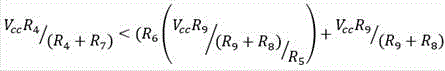
wherein,
R 7: a seventh resistive element 2418;
R 6: a sixth resistive element 2416;
R 9: a ninth resistive element 2420;
R 8: an eighth resistive element 2419; and
R 5: a fifth resistive element 2413.
In an example embodiment, the values of the sixth resistive element 2416 and the fifth resistive element 2413 are selected as follows: the above condition described in equation 4 is true when the worker brings the first conductive pad 304 into contact with the second conductive pad 402. In an example embodiment, the value of the fourth resistive element 2302 becomes zero when a worker moving the scanning device 102 causes the first conductive pad 304 to contact the second conductive pad 402. Accordingly, the left-hand side (LHS) of equation 4 becomes zero, causing comparator 2402 to generate the first trigger signal.
For example, when the worker brings the first conductive pad 304 into contact with the second conductive pad 402, the first input terminal 2404 and the second input terminal 2406 of the comparator 2402 receive a voltage signal according to the condition mentioned in equation 5. In some examples, the value of the voltage received at the first input terminal 2404 is greater than the value of the voltage received at the second input terminal 2406. Thus, the comparator 2404 generates a first trigger signal.
Further, in an example scenario in which glove 104 is wet, the value of fourth resistive element 2302 is not zero. Accordingly, the first input terminal 2404 and the second input terminal 2406 receive the value of the voltage according to the condition mentioned in equation 5 (e.g., LHS of equation 5 is not zero). In some examples, the value of the voltage received at the first input terminal 2404 is less than the value of the voltage received at the second input terminal 2406. Therefore, the comparator 2402 does not generate the first trigger signal.
As discussed in connection with fig. 21, communication interface 2114 facilitates the transmission and reception of messages/data from various computing devices. In some example embodiments, the communication interface 2114 may utilize the antenna elements to transmit data/messages to the mobile scanning device 102 and receive data/messages from the mobile scanning device 102. In some embodiments, the antenna elements may be woven on the glove 104, as further described in connection with fig. 25A and 25B.
Fig. 25A and 25B illustrate a top view 2500A of glove 104 and a top view 2500B of glove 104, respectively, that is inside-out according to one or more embodiments described herein.
Referring to top view 2500A, on the outer surface 210 of glove 104, an antenna element 2502 is woven. In an example embodiment, the antenna element 2502 is woven using the same conductive yarn used to weave the first and second conductive pads 304, 402.
Referring to top view 2500B, on interior surface 502 of glove 104, fourth conductive path 2504 is woven to connect antenna element 2502 to fourth conductive region 2506. In an example embodiment, the fourth conductive region 2506 is woven around the perimeter of the first via 219 d. When mobile scanning device 102 is coupled with glove 104, antenna element 2502 is coupled with communication interface 2114 of mobile scanning device 102 through the fourth conductive region.
Fig. 26 illustrates a flow diagram 2600 for a method of operating a mobile scanning device 102 in accordance with one or more embodiments described herein.
At step 2602, the mobile scanning device 102 includes means, such as the control system 2108, the processor 2110, the gesture recognition unit 2116, or the like, for receiving input relating to a mode of operation of the mobile scanning device 102. In an example embodiment, the gesture recognition unit 2116 may be configured to receive input from a worker (using the mobile scanning device 102) through a touch panel provided on the display screen 2106. In an alternative embodiment, the gesture recognition unit 2116 may be configured to provide input by moving one or more buttons (not shown) on the scanning device 102.
Prior to receiving input from the worker, the gesture recognition unit 2116 may cause the display screen 2106 to display one or more modes of operation of the mobile scanning device 102. The one or more modes of operation may include, but are not limited to: a gesture association mode and an operation mode. A worker using the mobile scanning device 102 may provide input to select an option corresponding to a mode of operation of the mobile scanning device 102 in which she wishes to operate the mobile scanning device 102. For example, the worker may provide input through the display screen 2106 to operate the mobile scanning device 102 in a gesture-associated mode.
At step 2604, the mobile scanning device 102 includes means, such as the control system 2108, the processor 2110, the gesture recognition unit 2116 or the like, for determining a mode of operation of the mobile scanning device 102 based on the received input. In an example embodiment, if the gesture recognition unit 2116 determines that the input corresponds to selection of a gesture association mode, the gesture recognition unit 2116 may be configured to perform step 2606.
At step 2606, the mobile scanning device 102 includes means, such as the control system 2108, the processor 2110, the gesture recognition unit 2116, or the like, for operating the mobile scanning device 102 in a gesture-associated mode. The operation of the mobile scanning device 102 in the gesture association mode is described in connection with FIG. 27.
If the gesture recognition unit 2116 determines at step 2604 that the input corresponds to selection of an operational mode, the gesture recognition unit 2116 may be configured to perform step 2608. At step 2608, the mobile scanning device 102 includes means, such as the control system 2108, the processor 2110, the gesture recognition unit 2116, or the like, for operating the mobile scanning device 102 in an operational mode. The operation of the mobile scanning device 102 in the operational mode is described in connection with fig. 29.
Fig. 27 illustrates a flowchart 2700 for operating the mobile scanning device 102 in a gesture-associated mode in accordance with one or more embodiments described herein.
At step 2702, the mobile scanning device 102 includes means, such as the control system 2108, the processor 2110, the gesture recognition unit 2116, or the like, for causing the display screen 2106 to display a list of operations that the mobile scanning device 102 is configured to perform. For example, the operation list may include, but is not limited to: triggering the image capture assembly 116, activating the display screen 2106, scrolling data displayed on the display screen 2106, etc. In an example embodiment, the operational list may be pre-programmed in the mobile scanning device 102 and may be pre-stored in the memory device 2112 of the control system 2108. The gesture recognition unit 2116 may be configured to retrieve the operation list from the memory device 2112 and display the operation list on the display screen 2106.
At step 2704, the mobile scanning device 102 includes means, such as the control system 2108, the processor 2110, the gesture recognition unit 2116, etc., for receiving an input to select an operation in the list of operations displayed on the display screen 2106. In an example embodiment, the gesture recognition unit 2116 may be configured to receive input from a worker related to selection of an operation to move the scanning device 102. In some embodiments, the worker may provide input through a touch panel included in the display screen 2106. In an alternative embodiment, the worker may provide the input by moving one or more buttons (not shown) on the scanning device 102.
At step 2706, the mobile scanning device 102 includes means, such as the control system 2108, the processor 2110, the gesture recognition unit 2116 or the like, for receiving at least one of the first trigger signal or the second trigger signal. As previously discussed, the first trigger circuit 2102 generates a first trigger signal when a worker wearing the glove 104 contacts the first conductive pad 304 with the second conductive pad 402. To do so, as discussed, the worker would perform gesture 2000A to cause first conductive pad 304 to contact second conductive pad 402. Accordingly, receipt of the first trigger signal (from the first trigger circuit 2102) by the gesture recognition unit 2116 may indicate that the worker may have performed the gesture 2000A. Similarly, receipt of the second trigger signal (from the second trigger circuit 2104) may indicate that the worker is likely to have performed the gesture 2000B. Thus, receipt of the first trigger signal and/or the second trigger signal may indicate that the worker may have performed a gesture using the glove 104.
At step 2708, the mobile scanning device 102 includes means, such as the control system 2108, the processor 2110, the gesture recognition unit 2116, or the like, for recognizing the type of gesture performed by the worker. The recognition of the type of gesture performed by the worker is further described in connection with FIG. 28.
Fig. 28 illustrates a flow diagram 2800 of a method for identifying the type of gesture performed by a worker in accordance with one or more embodiments described herein.
At step 2802, the mobile scanning device 102 includes means, such as the control system 2108, the processor 2110, the gesture recognition unit 2116, or the like, for determining whether the gesture recognition unit 2116 received the first trigger signal from the first trigger circuit 2102 or the second trigger signal from the second trigger circuit 2104. In the event that the gesture recognition unit 2116 receives the first trigger signal, the gesture recognition unit 2116 may determine that the worker may have caused the first conductive pad 304 to contact the second conductive pad 402. Accordingly, the gesture recognition unit 2116 may perform step 2804.
At step 2804, the mobile scanning device 102 includes means, such as the control system 2108, the processor 2110, the gesture recognition unit 2116, or the like, for determining whether the gesture recognition unit 2116 received a second trigger signal after receipt of the first trigger signal. In an example embodiment, receipt of the second trigger signal indicates that the worker has caused the first conductive pad 304 to contact the third conductive pad 1902. Further, receiving the second trigger signal after receiving the first trigger signal indicates that the worker may first cause the first conductive pad 304 to contact the second conductive pad 402 and subsequently cause the first conductive pad 304 to contact the third conductive pad 1902, thereby performing the slide-down gesture 2000C. As discussed, to perform the slide down gesture 2000C, a worker may slide the first conductive pad 304 (woven on the thumb region 305) over the back 202 of the middle finger region 404 from the second end 203 of the glove 104 toward the palm region 206.
In the case where the gesture recognition unit 2116 receives the second trigger signal after receiving the first trigger signal, the gesture recognition unit 2116 may perform step 2806. At step 2806, the mobile scanning device 102 includes means, such as the control system 2108, the processor 2110, the gesture recognition unit 2116, etc., for determining that the gesture performed by the worker is the slide down gesture 2000C.
However, in case the gesture recognition unit 2116 does not receive the second trigger signal, the gesture recognition unit 2116 is configured to perform step 2808. At step 2808, the mobile scanning device 102 includes means, such as the control system 2108, the processor 2110, the gesture recognition unit 2116, or the like, for determining whether a predetermined time period has elapsed. If the gesture recognition unit 2116 determines that the predetermined time period has elapsed, the gesture recognition unit 2116 may be configured to perform step 2810. However, if the gesture recognition unit 2116 recognizes that the predetermined period of time has not elapsed, the gesture recognition unit 2116 may be configured to repeat step 2804.
At step 2810, the mobile scanning device 102 includes means, such as the control system 2108, the processor 2110, the gesture recognition unit 2116, or the like, for determining that the gesture performed by the worker is the gesture 2000A. As discussed, to perform the gesture 2000A, the worker may cause the first conductive pad 304 to contact the second conductive pad 402.
Referring to step 2802, in the case where the gesture recognition unit 2116 receives a second trigger signal from a second trigger circuit, the gesture recognition unit 2116 may be configured to perform step 2812. At step 2812, the mobile scanning device 102 includes means, such as the control system 2108, the processor 2110, the gesture recognition unit 2116, or the like, for determining whether the gesture recognition unit 2116 received the first trigger signal after receipt of the second trigger signal. In an example embodiment, receipt of the first trigger signal indicates that the worker has caused the first conductive pad 304 to contact the second conductive pad 402. Further, receipt of the first trigger signal after receipt of the second trigger signal indicates that the worker may first cause the first conductive pad 304 to contact the third conductive pad 1902 and subsequently cause the first conductive pad 304 to contact the second conductive pad 402, thereby performing gesture 2000D. As discussed, to perform the gesture 2000D, the worker may have slid the first conductive pad 304 (woven on the thumb region 305) over the rear 202 of the middle finger region 404 from the third conductive pad 1902 toward the second end 203 of the glove 104.
In the case where the gesture recognition unit 2116 receives the first trigger signal after the reception of the second trigger signal, the gesture recognition unit 2116 may perform step 2814. At step 2814, the mobile scanning device 102 includes means, such as the control system 2108, the processor 2110, the gesture recognition unit 2116, or the like, for determining that the gesture performed by the worker is the gesture 2000D.
However, in case the gesture recognition unit 2116 does not receive the first trigger signal, the gesture recognition unit 2116 is configured to perform step 2816. At step 2816, the mobile scanning device 102 includes means, such as the control system 2108, the processor 2110, the gesture recognition unit 2116, or the like, for determining whether a predetermined time period has elapsed. If the gesture recognition unit 2116 determines that the predetermined time period has elapsed, the gesture recognition unit may be configured to perform step 2818. At step 2818, the mobile scanning device 102 includes means, such as the control system 2108, the processor 2110, the gesture recognition unit 2116, or the like, for determining that the gesture performed by the worker is the gesture 2000B.
However, if the gesture recognition unit 2116 determines that the predetermined time period has not elapsed at step 2816, the gesture recognition unit 2116 may be configured to repeat step 2812.
In some embodiments, the scope of the present disclosure is not limited to recognizing only four gesture types (e.g., gesture 2000A, gesture 2000B, gesture 2000C, and gesture 2000D). In an example embodiment, the gesture recognition unit 2116 may be configured to recognize more than four gestures based on various permutations and combinations of at least one of the order of receipt of the first and second trigger signals or the durations of receipt of the first and second trigger signals.
FIG. 29 illustrates another flow diagram 2900 for a method of identifying the type of gesture performed by a worker in accordance with one or more embodiments described herein.
At step 2902, the mobile scanning device 102 includes means, such as the control system 2108, the processor 2110, the gesture recognition unit 2116, or the like, for determining whether the gesture recognition unit 2116 received the first trigger signal from the first trigger circuit 2102 or the second trigger signal from the second trigger circuit 2104. In the event that the gesture recognition unit 2116 receives the first trigger signal, the gesture recognition unit 2116 may determine that the worker is likely to cause the first conductive pad 304 to contact the second conductive pad 402. Accordingly, the gesture recognition unit 2116 may perform step 2904. However, if the gesture recognition unit 2116 determines that the gesture recognition unit receives the second trigger signal, the gesture recognition unit 2116 may perform step 2912.
At step 2904, the mobile scanning device 102 includes means, such as the control system 2108, the processor 2110, the gesture recognition unit 2116, or the like, for determining a duration of receipt of the first trigger signal. At step 2906, the mobile scanning device 102 includes means, such as the control system 2108, the processor 2110, the gesture recognition unit 2116, or the like, for determining whether the duration of receipt of the first trigger signal is less than a first predetermined duration threshold. If the gesture recognition unit 2116 determines that the duration of the reception of the first trigger signal is less than the first predetermined duration threshold, the gesture recognition unit 2116 may perform step 2908. However, if the gesture recognition unit 2116 determines that the duration of the reception of the first trigger signal is greater than the first predetermined duration threshold, the gesture recognition unit 2116 may be configured to perform step 2910.
At step 2908, the mobile scanning device 102 includes means, such as the control system 2108, the processor 2110, the gesture recognition unit 2116, or the like, for determining that the worker performed the first gesture type.
At step 2910, the mobile scanning device 102 includes means, such as the control system 2108, the processor 2110, the gesture recognition unit 2116, or the like, for determining that the worker performed the second gesture type.
Referring back to 2902, if the gesture recognition unit 2116 determines that a second trigger signal is received, at step 2912, the mobile scanning device 102 includes means, such as the control system 2108, the processor 2110, the gesture recognition unit 2116, or the like, for determining a duration of receipt of the second trigger signal. Thereafter, at step 2914, the mobile scanning device 102 includes means, such as the control system 2108, the processor 2110, the gesture recognition unit 2116, or the like, for determining whether the duration of the reception of the second trigger signal is less than a second predetermined duration threshold. If the gesture recognition unit 2116 determines that the duration of the reception of the second trigger signal is less than the second predetermined duration threshold, the gesture recognition unit 2116 may perform step 2916. However, if the gesture recognition unit 2116 determines that the duration of the reception of the second trigger signal is greater than the second predetermined duration threshold, the gesture recognition unit 2116 may be configured to perform step 2918. In some examples, the first predetermined duration threshold has the same value as the second predetermined duration threshold. Further, both the first predetermined duration threshold and the second predetermined duration threshold are predefined during manufacturing of the mobile scanning device 102.
At step 2916, the mobile scanning device 102 includes means, such as the control system 2108, the processor 2110, the gesture recognition unit 2116, or the like, for determining that the worker performed the third gesture type.
At step 2918, the mobile scanning device 102 includes means, such as the control system 2108, the processor 2110, the gesture recognition unit 2116, or the like, for determining that the worker performed the fourth gesture type.
In some examples, the gesture recognition unit 2116 may determine the gesture type based on a combination of a duration of receipt of the first trigger signal or the second trigger signal and an order of receipt of the first trigger signal and the second trigger signal. For example, if the gesture recognition unit 2116 receives a first trigger signal for a first predetermined duration threshold and subsequently receives a second trigger signal, the gesture recognition unit 2116 may determine that the worker performed gesture 2000C. Similarly, if the gesture recognition unit 2116 receives the second trigger signal for a second predetermined duration threshold and subsequently receives the first trigger signal, the gesture recognition unit 2116 may determine that the worker performed gesture 2000D.
Referring back to fig. 27, at step 2710, the mobile scanning device 102 includes means, such as the control system 2108, the processor 2110, the gesture recognition unit 2116, or the like, for associating the recognized gesture type with the operation of the selected mobile scanning device 102 (selected at step 2704). In an example embodiment, the gesture recognition unit 2116 may create a lookup table indicating associations between recognized gesture types and selected operations of the mobile scanning device 102. The following table illustrates an example lookup table:
| gesture type | Operation of the |
| |
Trigger |
| Gesture 2000B | Cancellation |
| Gesture 2000C | Scrolling data displayed on |
| Gesture | |
| 2000D | Scroll down data displayed on |
Table 1: a look-up table illustrating associations between gesture types and operation of the mobile scanning device 102 is illustrated.
Fig. 30 illustrates a flowchart 3000 of a method for operating the mobile scanning device 102 in an operational mode according to one or more embodiments described herein.
At step 3002, the mobile scanning device 102 includes means, such as the control system 2108, the processor 2110, the gesture recognition unit 2116, etc., for identifying the type of gesture performed by the worker wearing the glove 104 and using the mobile scanning device 102. In an example embodiment, the gesture recognition unit 2116 may determine the type of gesture using a method similar to that described in flowchart 2800. For example, the gesture recognition unit 2116 may determine whether it has received the first trigger signal or the second trigger signal. In the case where the gesture recognition unit 2116 receives the first trigger signal, the gesture recognition unit 2116 may determine whether it receives the second trigger signal after the reception of the first trigger signal. In the event that the gesture recognition unit 2116 receives the second trigger signal after receipt of the first trigger signal, the gesture recognition unit 2116 determines that the worker performed the gesture 2000C. However, in a case where the gesture recognition unit 2116 does not receive the second trigger signal after the reception of the first trigger signal, the gesture recognition unit 2116 determines that the worker performed the gesture 2000A. Similarly, the gesture recognition unit 2116 may recognize gestures 2000B and 2000D.
At step 3004, the mobile scanning device 102 includes means, such as the control system 2108, the processor 2110, the gesture recognition unit 2116 or the like, for determining an operation of the mobile scanning device 102 associated with the recognized gesture. In an example embodiment, the gesture recognition unit 2116 may utilize a look-up table (e.g., table 1) to determine operation of the mobile scanning device 102. For example, if the gesture recognition unit 2116 determines that the gesture performed by the worker is the gesture 2000A, the gesture recognition unit 2116 may determine to trigger the image capture assembly 116. Further, the gesture recognition unit 2116 transmits the determined operation to the processor 2110.
At step 3006, the mobile scanning device 102 includes means, such as the control system 2108, processor 2110, etc., for performing the determined operation. For example, the determined operation is to trigger the image capture assembly 116, and the processor 2110 may cause the image capture assembly 116 to capture an image of the machine-readable indicia.
In some example embodiments, certain of the operations herein may be modified or further amplified as described below. Furthermore, in some embodiments, additional optional operations may also be included. It will be appreciated that each of the modifications, optional additions or amplifications described herein may be included with the operations herein either alone or in combination with any other of the features described herein.
The foregoing method descriptions and process flow diagrams are provided merely as illustrative examples and are not intended to require or imply that the steps of the various embodiments must be performed in the order presented. As will be appreciated by those skilled in the art, the order of the steps in the foregoing embodiments may be performed in any order. Words such as "thereafter," "then," "next," etc. are not intended to limit the order of the steps; these words are simply used to guide the reader through the description of the methods. Furthermore, any reference to claim elements in the singular, for example, using the articles "a," "an," or "the," is not to be construed as limiting the element to the singular.
The hardware used to implement the various illustrative logics, logical blocks, modules, and circuits described in connection with the aspects disclosed herein may include a general purpose processor, a Digital Signal Processor (DSP), a special purpose processor such as an Application Specific Integrated Circuit (ASIC) or Field Programmable Gate Array (FPGA), a programmable logic device, discrete gate or transistor logic, discrete hardware components, or any combination thereof designed to perform the functions described herein. A general purpose processor may be a microprocessor, but in the alternative, the processor may be any conventional processor, controller, microcontroller, or state machine. A processor may also be implemented as a combination of computing devices, e.g., a combination of a DSP and a microprocessor, a plurality of microprocessors, one or more microprocessors in conjunction with a DSP core, or any other such configuration. Alternatively or additionally, some steps or methods may be performed by circuitry that is specific to a given function.
In one or more example embodiments, the functions described herein may be implemented by dedicated hardware or by a combination of hardware programmed by firmware or other software. In implementations that rely on firmware or other software, the instructions may be stored as executions in one or more non-transitory computationsThe functions are carried out as a result of one or more instructions on a machine-readable medium and/or one or more non-transitory processor-readable media. These instructions may be implemented by one or more processor-executable software modules residing on one or more non-transitory computer-readable or processor-readable storage media. In this regard, a non-transitory computer-readable or processor-readable storage medium may include any storage media that can be accessed by a computer or a processor. By way of example, and not limitation, such non-transitory computer-readable or processor-readable media can comprise RAM, ROM, EEPROM, FLASH memory, disk storage, magnetic storage devices, and the like. Disk storage, as used herein, includes Compact Disk (CD), laser disk, optical disk, Digital Versatile Disk (DVD), floppy disk, and Blu-ray diskTMOr other storage devices that store data magnetically or optically with a laser. Combinations of the above types of media are also included within the scope of the term non-transitory computer-readable and processor-readable media. Additionally, any combination of instructions stored on one or more non-transitory processor-readable or computer-readable media may be referred to herein as a computer program product.
Many modifications and other embodiments of the inventions set forth herein will come to mind to one skilled in the art to which these inventions pertain having the benefit of the teachings presented in the foregoing descriptions and the associated drawings. Although the figures show only certain components of the devices and systems described herein, it is to be understood that various other components may be used in conjunction with the provisioning management system. Therefore, it is to be understood that the inventions are not to be limited to the specific embodiments disclosed and that modifications and other embodiments are intended to be included within the scope of the appended claims. Further, the steps in the methods described above may not necessarily occur in the order depicted in the figures, and in some cases, one or more of the depicted steps may occur substantially simultaneously, or additional steps may be involved. Although specific terms are employed herein, they are used in a generic and descriptive sense only and not for purposes of limitation.
Claims (34)
1. A glove, comprising:
a front portion;
a rear portion, wherein the front portion and the rear portion are seamlessly woven to define:
the area of the palm part is provided with a plurality of concave parts,
a plurality of finger regions extending outwardly from the palm region,
a first conductive pad woven on a front portion of the glove, wherein the first conductive pad is woven on a distal portion of a first finger region of the plurality of finger regions; and
a second conductive pad woven on a back portion of the glove, wherein the second conductive pad is woven on a second finger region of the plurality of finger regions, an
Wherein the electronic device is removably attached to the rear portion and is in electrical communication with the first conductive pad and the second conductive pad, wherein with the electronic device attached, the electronic device is triggered with the first conductive pad contacting the second conductive pad.
2. The glove of claim 1, wherein the back portion of the glove further comprises:
an outer surface; and
an inner surface, wherein the outer surface defines a plurality of first through-holes in a palm region of the glove, and wherein each first through-hole extends from the outer surface of the rear portion to the inner surface of the rear portion.
3. The glove of claim 2, further comprising:
a first conductive path woven on an interior surface of the rear portion of the glove, wherein the first conductive path is electrically coupled to the first conductive pad;
a second conductive path knitted on an interior surface of the back portion of the glove, wherein the second conductive path is electrically coupled to the second conductive pad;
a first conductive region woven on a perimeter of a first via of the plurality of first vias, wherein a first conductive path electrically couples the first conductive region with the first conductive pad; and
a second conductive region woven on a perimeter of another first via of the plurality of first vias, wherein the second conductive path electrically couples the second conductive region with the second conductive pad.
4. The glove of claim 2, wherein the first plurality of vias are configured to receive a plurality of couplers.
5. The glove of claim 4, wherein a pad is received on an outer surface of the rear portion of the glove, wherein the pad further comprises:
a plurality of second through holes, wherein the pad is received on the glove in a manner such that the plurality of first through holes on the glove are aligned with the plurality of second through holes on the pad.
6. The glove of claim 5, wherein the plurality of couplers extend through the plurality of second through holes.
7. The glove of claim 6, wherein an electronic device is attached to the pad by the plurality of couplers.
8. The glove of claim 4, wherein the electronic device comprises an adapter module, wherein the adapter module comprises a plurality of snaps, and wherein the electronic device is attached to the glove by snap-fitting the plurality of snaps to the plurality of couplers.
9. The glove of claim 2, further comprising:
a third conductive pad woven on the back portion of the glove, wherein the third conductive pad is woven on a third finger region of the plurality of finger regions;
a third conductive region woven on a perimeter of a first through-hole of the plurality of first through-holes, wherein the third conductive region is woven on an interior surface of the rear portion of the glove; and
a third conductive path knitted on an interior surface of the back portion of the glove, wherein the third conductive path electrically couples the third conductive pad with the third conductive region.
10. The glove of claim 2, further comprising:
an antenna element formed on an outer surface of the glove;
a fourth conductive region woven on a perimeter of a first through-hole of the plurality of first through-holes, wherein the fourth conductive region is woven on an interior surface of the rear portion of the glove; and
a fourth conductive path knitted on an interior surface of the back portion of the glove, wherein the fourth conductive path electrically couples the antenna element with the fourth conductive region.
11. The glove of claim 1, wherein the first conductive pad and the second conductive pad are formed from conductive yarns.
12. The glove of claim 11, wherein the conductive yarn is selected from the group consisting of silver-coated nylon and silver-coated polyester or polyethylene.
13. The glove of claim 11, wherein the front portion of the glove has an outer surface, wherein an abrasive coating is disposed on the outer surface of the front portion of the glove.
14. A glove according to claim 13, wherein the abrasive coating has a thickness of at most 0.6 mm.
15. The glove of claim 13, wherein the abrasive coating has a thickness such that the conductive yarns woven to form the first conductive pad are exposed to the ambient environment surrounding the glove.
16. An assembly of a mobile scanning device and a glove, the assembly comprising:
a glove, comprising:
a front portion;
a rear portion, wherein the front portion and the rear portion are seamlessly woven to define:
the area of the palm part is provided with a plurality of concave parts,
a plurality of finger regions extending outwardly from the palm region;
a first conductive pad woven on a front portion of the glove, wherein the first conductive pad is woven on a distal portion of a first finger region of the plurality of finger regions; and
a second conductive pad woven on the back portion of the glove, wherein the second conductive pad is woven on a second finger region of the plurality of finger regions; and
a mobile scanning device removably attached to the rear portion and in electrical communication with the first and second conductive pads,
wherein, with the mobile scanning device attached, the mobile scanning device is triggered with the first conductive pad contacting the second conductive pad.
17. The assembly of claim 16, wherein the back of the glove further comprises:
an outer surface; and
an inner surface, wherein the outer surface defines a plurality of first through-holes in a palm region of the glove, and wherein each first through-hole extends from the outer surface of the rear portion to the inner surface of the rear portion.
18. The assembly of claim 17, wherein the plurality of first vias are configured to receive a plurality of couplers.
19. The assembly of claim 18, wherein the mobile scanning device further comprises an adaptor module having a plurality of snaps, wherein the plurality of snaps snap into fit with the plurality of couplers to removably attach the mobile scanning device with the glove.
20. The assembly of claim 16, wherein the first and second conductive pads are formed from conductive yarn.
21. A method for operating a mobile scanning device mounted on a glove, the method comprising:
receiving, by a processor, an input to operate a mobile scanning device in a gesture-associated mode, wherein operating the mobile scanning device in the gesture-associated mode comprises:
receiving, by a processor, at least one of a first trigger signal or a second trigger signal when a worker performs a gesture while wearing a glove;
identifying, by the processor, a type of gesture performed by the worker wearing the glove based on receipt of at least one of the first trigger signal or the second trigger signal; and
the recognized gesture type is associated with an operation of the mobile scanning device.
22. The method of claim 21, wherein the gesture performed while wearing the glove corresponds to the worker causing the one or more conductive pads to contact each other for at least a predetermined duration or causing the one or more conductive pads to contact each other in a predetermined order.
23. The method of claim 22, wherein the one or more conductive pads are in electrical communication with the mobile scanning device attached to the glove.
24. The method of claim 21, wherein the type of gesture is identified based on at least a duration of receipt of the first trigger signal or the second trigger signal.
25. The method of claim 21, wherein the type of gesture is identified based on an order of receipt of at least one of the first trigger signal or the second trigger signal.
26. The method of claim 21, further comprising receiving, by the processor, an input to operate the mobile scanning device in an operational mode, wherein operating the mobile scanning device in the operational mode comprises:
receiving, by the processor, at least one of the first trigger signal or the second trigger signal indicative of another gesture performed by the worker;
identifying, by the processor, a type of another gesture performed by the worker based on the order of receipt of at least one of the first trigger signal or the second trigger signal;
determining, by the processor, an operation to perform on the mobile scanning device based on the type of the recognized another gesture; and
an operation determined based on the type of the another gesture is performed on the mobile scanning device by the processor.
27. A triggering system, comprising:
a glove, wherein the glove comprises:
a front portion;
a rear portion, wherein the front portion and the rear portion are seamlessly woven to define:
palm area, and
a plurality of finger regions extending outwardly from the palm region,
a first conductive pad woven on a front portion of the glove, wherein the first conductive pad is woven on a distal portion of a first finger region of the plurality of finger regions;
a second conductive pad woven on the back portion of the glove, wherein the second conductive pad is woven on a second finger region of the plurality of finger regions; and
a third conductive pad woven on the back portion of the glove, wherein the third conductive pad is woven on the second finger region and spaced apart from the second conductive pad; and
a mobile scanning device removably attached to the rear of the glove such that the first, second, and third conductive pads are electrically coupled with the mobile scanning device, wherein the mobile scanning device comprises:
a first trigger circuit configured to generate a first trigger signal when the first conductive pad is brought into contact with the second conductive pad;
a second trigger circuit configured to generate a second trigger signal when the first conductive pad is brought into contact with the third conductive pad; and
a processor communicatively coupled to the first trigger circuit and the second trigger circuit, wherein the processor is configured to:
receiving at least one of a first trigger signal or a second trigger signal indicative of when a worker is performing a gesture while wearing a glove;
identifying a type of gesture performed by the worker based on receipt of at least one of a duration of receipt of the first trigger signal or the second trigger signal or an order of receipt of the first trigger signal and the second trigger signal; and
triggering a mobile scanning device based on the type of gesture recognized.
28. The trigger system of claim 27, wherein the processor is further configured to associate the type of gesture recognized with a predetermined operation of the mobile scanning device.
29. The trigger system of claim 27, wherein the back portion of the glove further comprises:
an outer surface; and
an inner surface, wherein the outer surface defines a plurality of first through-holes in a palm region of the glove, and wherein each first through-hole extends from the outer surface of the rear portion to the inner surface of the rear portion.
30. The trigger system of claim 29, wherein the glove further comprises:
a first conductive path woven on an interior surface of the rear portion of the glove, wherein the first conductive path is electrically coupled to the first conductive pad;
a second conductive path knitted on an interior surface of the back portion of the glove, wherein the second conductive path is electrically coupled to the second conductive pad;
a first conductive region woven on a perimeter of a first via of the plurality of first vias, wherein a first conductive path electrically couples the first conductive region with the first conductive pad; and
a second conductive region woven on a perimeter of another first via of the plurality of first vias, wherein the second conductive path electrically couples the second conductive region with the second conductive pad.
31. The trigger system of claim 29, wherein the first plurality of vias are configured to receive a plurality of couplers.
32. The trigger system of claim 31, wherein a pad is received on an outer surface of the rear portion of the glove, wherein the pad further comprises:
a plurality of second through holes, wherein the pad is received on the glove in a manner such that the plurality of first through holes on the glove are aligned with the plurality of second through holes on the pad.
33. The trigger system of claim 32, wherein the plurality of couplers extend through the plurality of second vias.
34. The trigger system of claim 33, wherein a mobile scanning device is attached to the pad by the plurality of couplers.
Priority Applications (2)
| Application Number | Priority Date | Filing Date | Title |
|---|---|---|---|
| CN201810783869.6A CN110728158B (en) | 2018-07-17 | 2018-07-17 | Device and system for triggering a mobile scanning device |
| US16/513,012 US11540568B2 (en) | 2018-07-17 | 2019-07-16 | Apparatuses, and systems for triggering a mobile scanning device |
Applications Claiming Priority (1)
| Application Number | Priority Date | Filing Date | Title |
|---|---|---|---|
| CN201810783869.6A CN110728158B (en) | 2018-07-17 | 2018-07-17 | Device and system for triggering a mobile scanning device |
Publications (2)
| Publication Number | Publication Date |
|---|---|
| CN110728158A true CN110728158A (en) | 2020-01-24 |
| CN110728158B CN110728158B (en) | 2024-05-03 |
Family
ID=69161068
Family Applications (1)
| Application Number | Title | Priority Date | Filing Date |
|---|---|---|---|
| CN201810783869.6A Active CN110728158B (en) | 2018-07-17 | 2018-07-17 | Device and system for triggering a mobile scanning device |
Country Status (2)
| Country | Link |
|---|---|
| US (1) | US11540568B2 (en) |
| CN (1) | CN110728158B (en) |
Cited By (2)
| Publication number | Priority date | Publication date | Assignee | Title |
|---|---|---|---|---|
| CN114811282A (en) * | 2021-01-27 | 2022-07-29 | 手持产品公司 | Attachment device |
| US12124993B1 (en) * | 2024-03-22 | 2024-10-22 | Rgis International Holdings, Llc | Scanning system using ring scanner and terminal device |
Families Citing this family (8)
| Publication number | Priority date | Publication date | Assignee | Title |
|---|---|---|---|---|
| US10817689B2 (en) * | 2017-12-21 | 2020-10-27 | Datalogic IP Tech, S.r.l. | Systems and methods for a scan engine coupled to a finger mount |
| DE102018112945B4 (en) * | 2018-05-30 | 2022-03-03 | Workaround Gmbh | Glove |
| USD951257S1 (en) * | 2018-11-28 | 2022-05-10 | Soo Hyun CHAE | Portable terminal |
| EP3685694B1 (en) * | 2019-01-25 | 2022-10-12 | Feig Electronic GmbH | Device for arranging on a hand with identification device arranged on the device and method for manufacturing the device |
| US11681369B2 (en) * | 2019-09-16 | 2023-06-20 | Iron Will Innovations Canada Inc. | Control-point activation condition detection for generating corresponding control signals |
| NL2026062B1 (en) * | 2020-07-15 | 2022-03-21 | Univ Delft Tech | A virtual reality wearable system |
| US11954556B1 (en) * | 2023-01-03 | 2024-04-09 | Datalogic Ip Tech S.R.L. | Wearable glove with auto recognition |
| US11921935B1 (en) * | 2023-02-13 | 2024-03-05 | Toshiba Global Commerce Solutions | Gesture-based wearable device having coded commands |
Citations (12)
| Publication number | Priority date | Publication date | Assignee | Title |
|---|---|---|---|---|
| US20020118123A1 (en) * | 2001-02-27 | 2002-08-29 | Kim Sung-Cheol | Space keyboard system using force feedback and method of inputting information therefor |
| US20080054062A1 (en) * | 2006-09-04 | 2008-03-06 | Intermec Ip Corp. | Tool belt with smart cell technology |
| US20090054077A1 (en) * | 2007-08-23 | 2009-02-26 | Telefonaktiebolaget Lm Ericsson (Publ) | Method and apparatus for sending data relating to a target to a mobile device |
| CN101501701A (en) * | 2005-04-22 | 2009-08-05 | 微软公司 | Integrated control for navigation, authentication, power on and rotation |
| US20090212979A1 (en) * | 2008-02-22 | 2009-08-27 | William Catchings | Glove-based input device |
| US8279091B1 (en) * | 2009-11-03 | 2012-10-02 | The United States Of America As Represented By The Secretary Of The Navy | RFID system for gesture recognition, information coding, and processing |
| US20130169420A1 (en) * | 2010-10-18 | 2013-07-04 | Blue Infusion Technologies, Llc | Electronic Control Glove |
| EP2624238A1 (en) * | 2012-02-02 | 2013-08-07 | Eurocopter España, S.A. | Virtual mock up with haptic hand held aid |
| US20140240214A1 (en) * | 2013-02-26 | 2014-08-28 | Jiake Liu | Glove Interface Apparatus for Computer-Based Devices |
| US20160162022A1 (en) * | 2014-12-08 | 2016-06-09 | Rohit Seth | Wearable wireless hmi device |
| US20170270331A1 (en) * | 2016-03-17 | 2017-09-21 | Baker Hughes Incorporated | Scanner gloves and real-time tracking system |
| CN107896508A (en) * | 2015-04-25 | 2018-04-10 | 肖泉 | Multiple target/end points can be used as(Equipment)" method and apparatus of the super UI " architectures of equipment, and correlation technique/system of the gesture input with dynamic context consciousness virtualized towards " modularization " general purpose controller platform and input equipment focusing on people of the integration points of sum |
Family Cites Families (16)
| Publication number | Priority date | Publication date | Assignee | Title |
|---|---|---|---|---|
| US5250790A (en) | 1988-05-11 | 1993-10-05 | Symbol Technologies, Inc. | Hand-mounted scanner with automatic manual initiation of reading indicia |
| US5763865A (en) | 1996-04-01 | 1998-06-09 | Symbol Technologies, Inc. | Reader module for reading bar code symbols when connected to or disconnected from a terminal module |
| US7393214B2 (en) | 2006-02-17 | 2008-07-01 | Centipede Systems, Inc. | High performance electrical connector |
| DE102011006834A1 (en) | 2011-04-06 | 2012-10-11 | Robert Bosch Gmbh | Leading ground contact by means of spring element |
| US9104271B1 (en) * | 2011-06-03 | 2015-08-11 | Richard Adams | Gloved human-machine interface |
| WO2013049861A1 (en) | 2011-09-29 | 2013-04-04 | Magic Leap, Inc. | Tactile glove for human-computer interaction |
| US10130128B2 (en) * | 2013-03-15 | 2018-11-20 | World Fibers, Inc. | Cut resistant gloves and methods of making same |
| USD747071S1 (en) * | 2013-06-28 | 2016-01-12 | UIDC/Altare Corporation | Knitted glove with conductive elements |
| DE102015111506A1 (en) | 2014-10-11 | 2016-04-14 | Workaround UG (haftungsbeschränkt) | Workwear unit, wristband, connector, glove, sensor module, as well as methods for collecting, documenting, analyzing, controlling and / or teaching processes |
| US9693592B2 (en) | 2015-05-27 | 2017-07-04 | Google Inc. | Attaching electronic components to interactive textiles |
| US9510649B1 (en) | 2015-07-20 | 2016-12-06 | Flextronics Ap, Llc | Using a snap button to make disconnectable connection of electronic devices to fabrics |
| CN206006056U (en) | 2015-08-27 | 2017-03-15 | 手持产品公司 | There are the gloves of measurement, scanning and display capabilities |
| WO2017075703A1 (en) | 2015-11-02 | 2017-05-11 | Omsignal Inc. | Biosensing garment |
| US10162414B2 (en) * | 2016-03-04 | 2018-12-25 | Htc Corporation | Wireless control device, position calibrator and accessory |
| US9693622B1 (en) | 2016-04-12 | 2017-07-04 | Symbol Technologies, Llc | Wearable device mount |
| US10310608B1 (en) * | 2016-06-24 | 2019-06-04 | Facebook Technologies, Llc | Wearable accessory for force feedback |
-
2018
- 2018-07-17 CN CN201810783869.6A patent/CN110728158B/en active Active
-
2019
- 2019-07-16 US US16/513,012 patent/US11540568B2/en active Active
Patent Citations (12)
| Publication number | Priority date | Publication date | Assignee | Title |
|---|---|---|---|---|
| US20020118123A1 (en) * | 2001-02-27 | 2002-08-29 | Kim Sung-Cheol | Space keyboard system using force feedback and method of inputting information therefor |
| CN101501701A (en) * | 2005-04-22 | 2009-08-05 | 微软公司 | Integrated control for navigation, authentication, power on and rotation |
| US20080054062A1 (en) * | 2006-09-04 | 2008-03-06 | Intermec Ip Corp. | Tool belt with smart cell technology |
| US20090054077A1 (en) * | 2007-08-23 | 2009-02-26 | Telefonaktiebolaget Lm Ericsson (Publ) | Method and apparatus for sending data relating to a target to a mobile device |
| US20090212979A1 (en) * | 2008-02-22 | 2009-08-27 | William Catchings | Glove-based input device |
| US8279091B1 (en) * | 2009-11-03 | 2012-10-02 | The United States Of America As Represented By The Secretary Of The Navy | RFID system for gesture recognition, information coding, and processing |
| US20130169420A1 (en) * | 2010-10-18 | 2013-07-04 | Blue Infusion Technologies, Llc | Electronic Control Glove |
| EP2624238A1 (en) * | 2012-02-02 | 2013-08-07 | Eurocopter España, S.A. | Virtual mock up with haptic hand held aid |
| US20140240214A1 (en) * | 2013-02-26 | 2014-08-28 | Jiake Liu | Glove Interface Apparatus for Computer-Based Devices |
| US20160162022A1 (en) * | 2014-12-08 | 2016-06-09 | Rohit Seth | Wearable wireless hmi device |
| CN107896508A (en) * | 2015-04-25 | 2018-04-10 | 肖泉 | Multiple target/end points can be used as(Equipment)" method and apparatus of the super UI " architectures of equipment, and correlation technique/system of the gesture input with dynamic context consciousness virtualized towards " modularization " general purpose controller platform and input equipment focusing on people of the integration points of sum |
| US20170270331A1 (en) * | 2016-03-17 | 2017-09-21 | Baker Hughes Incorporated | Scanner gloves and real-time tracking system |
Cited By (4)
| Publication number | Priority date | Publication date | Assignee | Title |
|---|---|---|---|---|
| CN114811282A (en) * | 2021-01-27 | 2022-07-29 | 手持产品公司 | Attachment device |
| US11844416B2 (en) | 2021-01-27 | 2023-12-19 | Hand Held Products, Inc. | Attachment device |
| CN114811282B (en) * | 2021-01-27 | 2024-01-02 | 手持产品公司 | Attachment device |
| US12124993B1 (en) * | 2024-03-22 | 2024-10-22 | Rgis International Holdings, Llc | Scanning system using ring scanner and terminal device |
Also Published As
| Publication number | Publication date |
|---|---|
| CN110728158B (en) | 2024-05-03 |
| US11540568B2 (en) | 2023-01-03 |
| US20200022433A1 (en) | 2020-01-23 |
Similar Documents
| Publication | Publication Date | Title |
|---|---|---|
| CN110728158B (en) | Device and system for triggering a mobile scanning device | |
| US7969410B2 (en) | Optically detecting click events | |
| US10514448B2 (en) | Proximity sensor, proximity illumination intensity sensor, electronic device, and proximity sensor calibration method | |
| US20190196535A1 (en) | Low-profile wearable scanning device | |
| US20040263473A1 (en) | Wearable finger montion sensor for sensing finger motion and method of sensing finger motion using the same | |
| CN104272225A (en) | Information processing device, information processing method, and program | |
| US10839182B2 (en) | Apparatus for reading information | |
| US20080129532A1 (en) | System and Method for Activating a Mobile Device | |
| US20130221099A1 (en) | Information processing device, information processing method and computer readable storage medium | |
| KR20180135992A (en) | Connectible component identification | |
| KR20200017157A (en) | Apparatus for outputting information regarding stylus pen connected with electronic device and method thereof | |
| CN105575317B (en) | Electronic device and display processing method | |
| US20240211079A1 (en) | Information input device, sensitivity determination method, and storage medium | |
| KR20190132506A (en) | Reading system and camera | |
| JP7024620B2 (en) | Portable information reader | |
| KR20170086464A (en) | Wearable device and its control method | |
| KR102580884B1 (en) | Electronic device performing operation based on a type of identified covers and method for operating thereof | |
| US11250225B2 (en) | Wrist-worn product code reader | |
| US11288470B2 (en) | Scanning device and method of automatically triggering operation through specific motion trajectory | |
| US11449695B2 (en) | Reading system and camera | |
| US20220155856A1 (en) | Electronic Devices and Corresponding Methods for Initiating Electronic Communications with a Remote Electronic Device | |
| US11935386B2 (en) | Auto-notification sensor for adjusting of a wearable device | |
| JP7495621B2 (en) | Information reading device | |
| US20240095942A1 (en) | Controller, control method, and wearable tracking system | |
| US11190674B2 (en) | Remote camera trigger |
Legal Events
| Date | Code | Title | Description |
|---|---|---|---|
| PB01 | Publication | ||
| PB01 | Publication | ||
| SE01 | Entry into force of request for substantive examination | ||
| SE01 | Entry into force of request for substantive examination | ||
| GR01 | Patent grant | ||
| GR01 | Patent grant |