CN103688604A - Design for retention base fixed on cover removal fixture - Google Patents
Design for retention base fixed on cover removal fixture Download PDFInfo
- Publication number
- CN103688604A CN103688604A CN201280035281.3A CN201280035281A CN103688604A CN 103688604 A CN103688604 A CN 103688604A CN 201280035281 A CN201280035281 A CN 201280035281A CN 103688604 A CN103688604 A CN 103688604A
- Authority
- CN
- China
- Prior art keywords
- equipment
- substrate
- clip
- release
- retaining clip
- Prior art date
- Legal status (The legal status is an assumption and is not a legal conclusion. Google has not performed a legal analysis and makes no representation as to the accuracy of the status listed.)
- Granted
Links
- 230000014759 maintenance of location Effects 0.000 title abstract 6
- 238000013461 design Methods 0.000 title description 8
- 239000000758 substrate Substances 0.000 claims description 90
- 238000000034 method Methods 0.000 abstract description 21
- 230000002349 favourable effect Effects 0.000 description 5
- 238000013459 approach Methods 0.000 description 4
- 238000009434 installation Methods 0.000 description 4
- 230000001154 acute effect Effects 0.000 description 2
- 238000005452 bending Methods 0.000 description 2
- 238000003780 insertion Methods 0.000 description 2
- 230000037431 insertion Effects 0.000 description 2
- 238000012423 maintenance Methods 0.000 description 2
- 238000013475 authorization Methods 0.000 description 1
- 238000010276 construction Methods 0.000 description 1
- 230000000994 depressogenic effect Effects 0.000 description 1
- 230000000694 effects Effects 0.000 description 1
- 239000003607 modifier Substances 0.000 description 1
- 238000007790 scraping Methods 0.000 description 1
- FCEVNJIUIMLVML-QPSVUOIXSA-N seneciphylline Chemical group O1C(=O)C(=C/C)\CC(=C)[C@@](C)(O)C(=O)OCC2=CCN3[C@H]2[C@H]1CC3 FCEVNJIUIMLVML-QPSVUOIXSA-N 0.000 description 1
- FCEVNJIUIMLVML-UHFFFAOYSA-N spartioidine Natural products O1C(=O)C(=CC)CC(=C)C(C)(O)C(=O)OCC2=CCN3C2C1CC3 FCEVNJIUIMLVML-UHFFFAOYSA-N 0.000 description 1
Images


Classifications
-
- H—ELECTRICITY
- H05—ELECTRIC TECHNIQUES NOT OTHERWISE PROVIDED FOR
- H05K—PRINTED CIRCUITS; CASINGS OR CONSTRUCTIONAL DETAILS OF ELECTRIC APPARATUS; MANUFACTURE OF ASSEMBLAGES OF ELECTRICAL COMPONENTS
- H05K5/00—Casings, cabinets or drawers for electric apparatus
- H05K5/02—Details
- H05K5/0217—Mechanical details of casings
- H05K5/0221—Locks; Latches
-
- H05K5/0013—
Landscapes
- Engineering & Computer Science (AREA)
- Microelectronics & Electronic Packaging (AREA)
- Connection Of Plates (AREA)
- Casings For Electric Apparatus (AREA)
Abstract
A method and apparatus for disassembling a set top box is disclosed. The method includes providing the set top box including: a top cover, a base, and cover retention clips, wherein the cover retention clips are V or U shaped for securing the top cover to the base, providing a release fixture including a retention clip release finger, inserting the release fixture into the set top box, disengaging the cover retention clips using the retention clip release finger, and removing the top cover from the base.
Description
The cross reference of related application
The application requires in the rights and interests of the U.S. Provisional Application No.61/508724 of submission on July 18th, 2011, and the full content of this provisional application is incorporated to herein as quoting.
Technical field
Such as the electronic equipment of Set Top Box or device can be the equipment with the assembling of a plurality of walls, wherein, can utilize a plurality of screws to fix at least one wall.Regrettably, the internal part that realization approaches these devices need to remove described a plurality of screw, and this can need to carry out extra operation to device conventionally.This extra operation can relate to the orientation (putting upside down or be placed in side such as make device by tumbler) of modifier conventionally, to find each screw.Subsequently, in the situation that device is put upside down or be placed in side, by remove a screw at every turn, carry out relieving attachment.Because each motion of device can vibration component, so can increase to this extra operation of this device the possibility of damaging internal part.In addition, remove and be re-engaged the chance that screw can present scratch device or strike off the screw thread of screw.
In view of conventionally approaching the internal part of electronic installation and approach the fact that internal part can be placed in internal part the risk of damage or electronic installation is placed in to the risk of scraping, so a kind of method that needs improved electronic device construction and fast, simply and securely open electronic installation.
In order to meet this demand, WO2010008360A1 discloses a kind of known system.Fig. 1 be in disassembly status according to the perspective view of the equipment of WO2010008360A1.Such as the equipment 1 of Set Top Box can comprise: housing, has the outer wall that limits inner space; Top 10, a plurality of connection folders 30 that there is inner surface 112 and extend from this surface, inside; And substrate 5.Substrate 5 has inner surface and a plurality of folder receiving member 20, and a plurality of folder receiving members extend from inner surface, engages and connects folder 30 so that top 10 is fixed to substrate 5.Substrate 5 also comprises at least one hole 7, and its release clip 50 that is suitable for allowing having a plurality of separating members 40 that slave plate 51 extends side by side departs from and presss from both sides receiving member 20.
According to the method for the described equipment 1 of the assembling of WO2010008360A1, comprise: by applying vertical power, substrate 5 and top 10 are pushed together; Make the connection folder 30 at top 10 contact the folder receiving member 20 of substrate 5 simultaneously; Laterally reorientate the grasping part 31 that connects folder 30; And grasping part 31 buckles are entered to their initial lateral attitude or some centre positions.Can exist and connect the horizontal and vertically overlapping of a part for folder 30 and a part for folder receiving member 20, this makes it possible to dismantle top 10 and substrate 5.The method also can comprise the step of detaching equipment, comprising: release clip is aimed to substrate 5; Release clip 50 is applied to linear force so that a plurality of separating members 40 that extend from the plate 51 of release clip 50 enter the hole of substrate 5; Substantially make separating member 40 contact grasping part 31 simultaneously; Laterally reorientate the grasping part 31 that connects folder 30, so that grasping part 31 departs from; And mention top 10.
Fig. 1 illustrate in disassembly status according to the equipment 1 of WO2010008360A1.Equipment 1 can be electronic equipment, such as Set Top Box.Equipment 1 can comprise the housing with the outer wall that limits inner space.Housing can hold various electronic units, such as processor, smart card assembly, tuner, fan, storage device etc.These parts can be supported in inner supporting structure 60, and inner supporting structure itself can have sidewall and substrate.Outer wall can be antetheca 8, rear wall 6, sidewall 4, top 10 and substrate 5.
In one example, each folder receiving member 20 has a hole 7.Yet in other example of WO2010008360A1, single hole 7 can be associated with a plurality of folder receiving members 20, and for a plurality of folder receiving members 20.
The top 10 of equipment 1 comprises outer surface 11 and inner surface 112.Top 10 also comprises a plurality of connection folders 30, and a plurality of connection folders are designed to engage or buckle enters in the folder receiving member 20 of substrate 5.A plurality of connection folders 30 are fixed to substrate 5 by top 10 effectively.
Statement " buckle " can mean that a part that connects a part for folder 30 and/or press from both sides receiving member 20 is flexibility or flexible, when applying vertical power substrate 5 and top 10 are pushed together to a part that makes to connect folder 30 and/or folder receiving member 20 and contact with box lunch, allow necessarily laterally reorientating or moving of arbitrary part.And, the generation when contact of laterally reorientating or move, and along contrary being moved further of vertical direction, increase under the effect of power along with connecting a part for folder 30 and/or folder receiving member 20.Power finally makes top 10 and substrate 5 in predetermined assembled state.The in the situation that of split dimension, the connection of having reorientated or having moved is pressed from both sides a part of 30 or is pressed from both sides receiving member 20 and can return to its initial lateral attitude or some centre positions, thereby it is horizontal and vertically overlapping to connect the part (for example shoulder) of pressing from both sides a part of 30 and/or pressing from both sides receiving member 20.Connect laterally causing top 10 and substrate 5 assemblings or be fixed together with vertically overlapping of a part for folder and/or a part for folder receiving member.Top 10 can not be by attempting to make the top 10 relatively vertically power separated with substrate 5 separated in non-wasting mode with substrate 5." buckle " is considered to mean towards the moving fast or immediately of initial condition conventionally, yet this moves can be slowly.
Inner supporting structure 60 can have hole or groove 9, and hole or groove can also be associated with hole 7, to allow for folder receiving member 20, reserves space.
Fig. 2 A and 2B are the exploded views of the connection folder of Fig. 1 equipment.Fig. 2 A illustrates from top two forks (two-prong) that 10 inner surface 12 extends and connects folder 30.Each fork has the grasping part 31 of the far-end that is positioned at downward or the portion 32 that extends internally.Grasping part 31 can have shoulder and downwards or away from shoulder end extend and with the acutangulate inclined side of shoulder shape.Inclined side can bend at least a portion surface and form acute angle with shoulder.In Fig. 2 A, the shoulder of grasping part 31 extends away from each other.
Fig. 2 B illustrates the example that single tine connects folder 30.This single tine has the grasping part 31 of the far-end that is positioned at downward or the portion 32 that extends internally.Grasping part 31 also can have shoulder and the inclined side downward or that extend away from inner surface 12 from shoulder end.A part for inclined side can form acute angle with shoulder.Described far-end can extend from top at least two kinds of different lengths.Extend with at least two kinds of different sizes at 31Ke Cong top, grasping part, is so more difficult to dismantle without authorization this equipment.
Fig. 3 is the perspective view being engaged into according to the connection folder in the folder receiving member of the mounting equipment of WO2010008360A1.Two forks that Fig. 3 illustrates Fig. 2 A connect the folder receiving member 20 how folder 30 engages substrate 5.Folder receiving member 20 extends from substrate 5, and has and be positioned at upwards or the shoulder 21 of the far-end of the portion 22 that extends internally.Fig. 3 illustrates the example in the hole 7 that can be formed in substrate 5.Each hole 7 can be corresponding to connecting the junction surface of folder 30 with folder receiving member 20.Upwards or the far-end of the portion 22 that extends internally can refer to the position away from substrate 5, the shoulder 21 of folder receiving member 20 extends in this position.The structure of folder receiving member 20 can have extra section or extend through the extension of shoulder.The far-end of folder receiving member 20 can refer to the position away from substrate 5, and the shoulder 21 of folder receiving member 20 extends in this position.
Fig. 3 illustrates and makes the corresponding shoulder of grasping part 31 extend through the shoulder 21 of folder receiving member 20 and buckle enters to press from both sides the grasping part 31 in receiving member 20.Corresponding shoulder can be overlapping, and contact with each other or located adjacent one another, thereby top 10 is fixed to substrate 5.
Fig. 3 also illustrates the antetheca 8 that remains on assembled state in the groove 3 in top 10 and substrate 5 by being positioned at.This illustrates another feature of WO2010008360A1, and example can comprise the some or all of walls that are held in place by the groove 3 in top 10 and/or substrate 5.Because this feature can be used less screw or not use screw (for the object of WO2010008360A1), so this feature is favourable.
Fig. 4 is the perspective view being engaged into according to another connection folder in the folder receiving member of the mounting equipment of WO2010008360A1.The single tine that Fig. 4 illustrates Fig. 2 B connects the folder receiving member 20 how folder 30 engages substrate 5.Fig. 4 also illustrates hole 7, and it can be formed in substrate 5, and to shown in folder receiving member 20 and to connect the joint of folder 30 relevant.Hole 7 can also be incision or be formed on the groove in substrate 5.Folder receiving member 20 engages and connects folder 30 in mode same as shown in Figure 3.
The key feature of WO2010008360A1 is, exists a plurality of connections folders 30 and folder receiving member 20 to engage, and in preferred example, at assembly process, can carry out described joint substantially simultaneously.Statement side by side can be used for comprising from one and joins the situation that another joint may exist some absent-mindedness to.For example,, for the comparable length about another joint large 5% of length of travel of a joint.It is favourable engaging simultaneously, and this is because it prevents top 10 with respect to substrate 5 torsions or tilts.Other element of WO2010008360A1 can comprise that the only single tine of the equipment of being arranged in 1 connects folder 30, only two forks and connects folder 30 or both combinations.
Fig. 5 is according to the perspective view of the mounting equipment of WO2010008360A1 and release clip.Fig. 5 introduces another element of WO2010008360A1, and wherein this equipment can be designed to by using individual tool linear movement 70 simple with and single to be easy to dismounting, and equipment 1 maintains in its normal operative orientation simultaneously.Described instrument can be release clip 50, and this release clip has a plurality of separating members 40 that slave plate 51 extends, so that connect folder 30, departs from from folder receiving member 20 simultaneously.The feature simultaneously departing from is favourable, and this is because it can prevent that top is with respect to torsion or the inclination of substrate 5.Separating member 40 is all designed to aim at hole 7, and contact connection folder 30.For detaching equipment 1, release clip 50 is placed on flat surfaces.Equipment 1 is aimed at release clip 50, and then place apparatus 1 in motion once, and pushes release clip 50 to.This motion makes separating member 40 will connect folder 30 from 20 disengagings of folder receiving member, as shown in Figures 6 and 7.
Fig. 6 is during each step of detaching equipment, according to the cross section of the equipment of WO2010008360A1 and release clip.Fig. 6 illustrates two forks connection folders 30 and how to depart from during the single linear movement 70 of Fig. 5.It is the U-shaped designs with smooth top edge that Fig. 6 A illustrates separating member 40, and described smooth top edge enters hole 7 and applies upwards or contact during inside power 53 grasping part 31 at separating member 40.Upwards or inside power 53 can cause grasping part 31 along direction 54 skews away from extending upward portion 22, make to lower extension 32 bendings and/or be bent to a position, in this position, the shoulder of grasping part 31 moves apart (clear) or moves through the shoulder 21 of folder receiving member 20.
When Fig. 6 B illustrates shoulder when grasping part 31 and moves apart or move through the shoulder 21 of folder receiving member 20 and separating member 40 and insert completely, the location of grasping part 31.Now, top 10 can be by simply mentioning and remove, as shown in Figure 6 C.Thereby Fig. 6 C illustrates when mentioning top 10 while allowing the parts in the equipment that approaches 1, connects the location of the grasping part 31 of folder 30.
By simply top 10 being placed on to the top of substrate 5, remove release clip 50, and substrate 5 is depressed or pressed at top 10 can easily re-assembly this assembly.Then, each connection folder 30 can be re-engaged in folder receiving member 20.
Fig. 7 is during each step of detaching equipment, according to another cross section of the equipment of WO2010008360A1 and release clip.Fig. 7 illustrates single tine connection folder 30 and how to depart from during the single linear movement 70 of Fig. 5.Fig. 7 A illustrates separating member 40 for having narrow edge, the width of this narrow edge and shoulder 21 measure-alike.Described size is such, when separating member 40 enters hole 7, and narrow edge contact grasping part 31.Separating member can apply upwards or inside power 53, cause grasping part 31 along direction 54 skews away from extending upward portion 22, make crooked to lower extension 32 and/or be bent to a position, in this position, the shoulder of grasping part 31 moves apart or moves through the shoulder 21 of folder receiving member 20.
When Fig. 7 B illustrates shoulder when grasping part 31 and moves apart or move through the shoulder 21 of folder receiving member 20 and separating member 40 and insert completely, single tine connects the location of the grasping part 31 of folder 30.Now, top 10 can be by simply mentioning and remove, as shown in Fig. 7 C.Thereby Fig. 7 C illustrates when mentioning top 10 while allowing the parts in the equipment that approaches 1, connects the location of the grasping part 31 of folder 30.
Although WO2010008360A1 has advantages of the prior art of being better than, some complexity of WO2010008360A1, and need to connect folder 30 from top or the horizontal inner of enclosing cover 10 to downward-extension.This means that internal circuit board and any other internal part can be designed to hold connection folder 30 and folder receiving member 20 then.
Need a kind of more simply design, it provides many advantages of WO2010008360A1, but more general, and does not need internal part (such as top board fin and circuit board) particular design to become to hold and be assemblied in to connect around folder and folder receiving member.In addition, need a kind of design and a kind of device, described design allows when Set Top Box is unclamped, and the top of Set Top Box rests on lateral attitude with respect to framework and the substrate of Set Top Box, and described device, for when top is removed, is fixed or maintenance Set Top Box.
Other known method can comprise: kicker magnet, can need hand to be placed on substrate and fixture to remove substrate; Locking devicen, the second motion that can be by user from fixture attached with untie substrate; And complex spring, from substrate, promote lid.
Summary of the invention
A kind of method and apparatus for demountor top box is disclosed.The method comprises provides the Set Top Box that comprises top cover, substrate and lid retaining clip, and wherein, lid retaining clip is V or U-shaped, for top cover is fixed to substrate; Provide and comprise that retaining clip discharges the release clip of finger; By in release clip insertion machine top box; Use retaining clip to discharge finger and make to cover retaining clip disengaging; And remove top cover from substrate.
Embodiments of the invention relate to a kind of equipment, comprising: top cover; Substrate; And lid retaining clip, wherein, lid retaining clip is V or U-shaped, for top cover is fixed to substrate.This equipment can be configured to release clip dismounting, and release clip comprises that retaining clip discharges finger.Lid retaining clip is fixed by top cover, and buckle enters in the hole of substrate.Release clip also comprises guiding piece, for auxiliary described equipment, aims at release clip.Release clip is assemblied in the opening of substrate of equipment.Release clip is at the sidewall of top cover and vertically between base frame sidewall, slide.Retaining clip is covered in release clip contact, and makes to cover retaining clip disengaging.When top cover is removed, release clip engages substrate and keeps substrate downward.When engaging, retaining clip discharges finger and fits in the hole of substrate.Lid retaining clip comprises sweep, and sweep extends beyond the upper bound in hole, to prevent retaining clip entanglement.And, drawing thus, this equipment can be configured to: by release clip, dismantle, release clip has guiding piece, for auxiliary equipment, aims at release clip; There is the opening for retaining clip release finger that is arranged in substrate; During dismantling, make release clip at the sidewall of top cover and vertically between base frame sidewall, slide; During dismantling, make release clip contact cover retaining clip and make to cover retaining clip to depart from; During dismantling, make release clip when top cover is removed, engage substrate and keep substrate down; Make retaining clip discharge finger fits in the hole of substrate when engaging; And during dismantling, make to cover retaining clip and comprise sweep, sweep extends beyond the upper bound in hole, to prevent that retaining clip from tangling.
Accompanying drawing explanation
By reference to the accompanying drawings, from the following explanation providing with exemplary form, can obtain better and understand in detail, in accompanying drawing:
Fig. 1 be in disassembly status according to the perspective view of the equipment of WO2010008360A1;
Fig. 2 A and 2B are the exploded views that the connection of the equipment of Fig. 1 is pressed from both sides;
Fig. 3 is the perspective view being engaged into according to the connection folder in the folder receiving member of the mounting equipment of WO2010008360A1;
Fig. 4 is the perspective view being engaged into according to another connection folder in the folder receiving member of the mounting equipment of WO2010008360A1;
Fig. 5 is according to the perspective view of the mounting equipment of WO2010008360A1 and release clip;
Fig. 6 is during each step of detaching equipment, according to the cross section of the equipment of WO2010008360A1 and release clip;
Fig. 7 is during each step of detaching equipment, according to another cross section of the equipment of WO2010008360A1 and release clip;
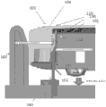
Fig. 8 is end view of the present disclosure, and wherein, the Set Top Box of assembling etc. is placed on release clip;
Fig. 9 is end view of the present disclosure, and wherein, Set Top Box etc. are placed on release clip completely, and in the state for dismantling; And
Figure 10 is the flow chart that uses the exemplary method that departs from fixture demountor top box.
Embodiment
Should be understood that the explanation of having simplified drawings and Examples, to illustrate with clear, understand the relevant element of the present invention, and eliminated well known in the art and and be not easy to understand better other element of the present invention and step.
Fig. 8 is end view of the present disclosure, and wherein, the Set Top Box of assembling etc. is placed on release clip.Fig. 8 illustrates end view of the present disclosure, and wherein, Set Top Box 101 grades of assembling are placed on release clip 150.
Set Top Box 101 or electronic installation can have and cover 110, and lid has the sidewall 104 to downward-extension.Sidewall 104 can be designed to keep covering retaining clip or connect folder 130.Connect folder 130 and can have curved shape, such as v shape or u shape, wherein, a side of V (or U) or fork can be maybe can have smooth or straight profile.A side or fork that V (or U) connects folder 130 can be attached to the inner side of sidewall 104 in vertical orientation.The second fork or opposite side that V (or U) connects folder 130 can make progress and extend internally, and have crooked end, and crooked end has flange, and the shape of flange is made buckle and entered in the hole 132 of vertical base frame sidewall 131 of substrate 105 of Set Top Box 101.V (or U) connects the flange of other fork of folder 130 can be crooked towards the first fork, and can have other bend upwards, and while making in connecting folder 130 joint inlet holes 132, bend is parallel to the first fork in addition.The upper bound that makes this other bend extend beyond hole 132 can prevent that folder from irreversibly tangling.This joint can make to cover 110 and lock onto the substrate 105 of Set Top Box 101, thereby fixes this Set Top Box 101 for using.
Release clip 150 can be similar with WO2010008360A1.Yet separating member (or lid retaining clip discharges finger) 140 can be designed to be positioned at substrate 105 circumferences around, and can be designed to be flexible.Release clip 150 comprises guiding piece 160, and guiding piece can be positioned at three sides or four sides, with auxiliary machine top box 101, aims at release clip 150.Separating member 140 can be designed to (1) and fit in the opening 151 of substrate 105 or Set Top Box 101 bottoms; (2) in the sidewall 104 of lid 110 and vertically slip between base frame sidewall 131; And the second fork of (3) contact connection folder 130, so that the second fork is away from vertically base frame sidewall 131 bendings, thereby flange is removed from the hole 132 of substrate 105, and separate locking closure 110.The top of separating member 140 can have the first rake that is positioned at separating member 140 ends, and it upwards bends and bends towards Set Top Box 101.This rake can contact the second fork, and makes the second fork crooked towards the first fork.The slope that the slope of the rake of separating member 140 can be pitched with second of folder 130 (flange portion below) is identical, or slope can at least have identical symbol.
In addition, separating member 140 can be flexible, and have with towards Set Top Box 101 inwardly towards relative the second side of the first rake.This second side can have the inclined upper (relative with the substrate of separating member) of extending from separating member 140 ends, and has the flange extending towards the first rake.At least a portion of this flange and inclined upper enters hole 131 can lock onto fixture by Set Top Box 101 via substrate 105, and liberation simultaneously covers 110 for removing.Fixture 150 and Set Top Box 101 can comprise respectively a plurality of separated folders and folder 140, engage and depart from can expect and occur simultaneously.
Fig. 9 is end view of the present disclosure, and wherein, Set Top Box etc. are placed on release clip completely, and in the state for dismantling.Fig. 9 illustrates one of a plurality of separated folders and folder 130, and it can interact simultaneously, to engage and to depart from folder 140.Fig. 9 illustrates the upper bond connection folder 130 that pore-forming 132 can be designed in hole 132, and with locking cover 110, the lower bond separating member 140 in hole 132, to keep substrate 105 to release clip 150, to separate locking closure 110.In other words, when having while covering 110, by being arranged in, covering latch piece or the projection 180 that retaining clip discharges the rear side of finger 140 (unclamp the connection of cover 110 from framework 105 (substrate) and press from both sides 130) and be pressed into framework.This action can keep substrate 105 to release clip 150, allows to be easy to remove to cover 110.When having removed lid 110 time, also the connection on removable lid 110 presss from both sides 130, thereby allowing to be easy to removes substrate 105 from release clip 150.
When separately, dismounting frame or release clip can allow lid to stay on substrate or framework.Yet when removing lid, release clip can keep substrate, this is favourable, because being can produce some frictions by desired the closely cooperating of forming portion part smooth-shaped.In the time of on being positioned at fixture, from substrate, mentioning lid and can pull substrate and fixture, and folder is re-engaged.The method can remain to framework by substrate, allows lid to remove.Once cover removes, latch piece automatically departs from from substrate, allows to remove substrate from fixture.
Although making separated folder is favourable around circumference, some connect jacodine position and become away from circumference.This can make in the situation that there is no suitable release clip, to be more difficult to device for opening.
Figure 10 is the flow chart that uses the exemplary method that departs from fixture demountor top box.As shown in figure 10, for the method for demountor top box, can comprise the Set Top Box (1000) that comprises top cover, substrate and lid retaining clip is provided.Lid retaining clip can be V or U-shaped, for top cover is fixed to substrate.The method also can comprise provides the release clip (1005) that comprises retaining clip release finger.The method also can comprise in release clip insertion machine top box (1010).The method also can comprise that using retaining clip to discharge finger makes to cover retaining clip disengaging (1015).The method also can comprise from substrate and removes top cover (1020).Providing Set Top Box (1000) afterwards, the method can comprise by by the hole of the lid retaining clip basement of top cover and top cover is fixed to substrate.
Although described embodiments of the invention, should understand, the modified example of these embodiment is in essence spirit of the present invention and scope.For example, feature of the present invention is that the Set Top Box with folder does not have any screw or the bolt that lid is remained to framework.The invention is not restricted to carry out any particular element of any specific function, some functions needn't with shown in occur in sequence.For example, in some cases, two or more method steps can different order or generation simultaneously.Especially in the situation that consider the explanation of methods described herein, these and other modified example of method disclosed herein is easy to understand, and considered to be in four corner of the present invention.
Claims (16)
1. an equipment, comprising:
Top cover;
Substrate; And
Lid retaining clip, wherein, described lid retaining clip is V or U-shaped, for top cover is fixed to substrate,
Wherein, described equipment is configured to utilize release clip dismounting, and described release clip comprises:
Retaining clip discharges finger.
2. equipment as claimed in claim 1, wherein, described lid retaining clip is fixed by top cover, and buckle enters in a hole of substrate.
3. equipment as claimed in claim 1, wherein, described release clip also comprises guiding piece, for auxiliary described equipment, aims at described release clip.
4. equipment as claimed in claim 1, wherein, described release clip fits in the opening of substrate of described equipment.
5. equipment as claimed in claim 1, wherein, described release clip is at the sidewall of top cover and vertically between base frame sidewall, slide.
6. equipment as claimed in claim 1, wherein, retaining clip cover in described release clip contact, and makes to cover retaining clip disengaging.
7. equipment as claimed in claim 1, wherein, when top cover is removed, described release clip engages substrate, and keeps substrate down.
8. equipment as claimed in claim 7, wherein, described retaining clip discharges finger and fits in a hole of substrate when engaging.
9. equipment as claimed in claim 2, wherein, described lid retaining clip comprises sweep, described sweep extends beyond the upper bound in described hole, to prevent that retaining clip from tangling.
10. equipment as claimed in claim 1, wherein, described equipment is also configured to dismantle by release clip, and described release clip has guiding piece, for auxiliary described equipment, aims at described release clip.
11. equipment as claimed in claim 1, wherein, described equipment is also configured with the opening for retaining clip release finger that is arranged in substrate.
12. equipment as claimed in claim 1, wherein, described equipment is also configured to make release clip during dismantling at the sidewall of top cover and vertically between base frame sidewall, slides.
13. equipment as claimed in claim 1, wherein, described equipment is also configured to make release clip contact to cover retaining clip during dismantling and makes to cover retaining clip depart from.
14. equipment as claimed in claim 1, wherein, described equipment is also configured to during dismantling, and makes release clip when top cover is removed, engage substrate and keep substrate down.
15. equipment as claimed in claim 14, wherein, described equipment is also configured to make retaining clip release finger to fit in a hole of substrate when engaging.
16. equipment as claimed in claim 2, wherein, described equipment is also configured to make to cover retaining clip when dismounting and comprises sweep, and described sweep extends beyond the upper bound in described hole, to prevent retaining clip entanglement.
Applications Claiming Priority (3)
| Application Number | Priority Date | Filing Date | Title |
|---|---|---|---|
| US201161508724P | 2011-07-18 | 2011-07-18 | |
| US61/508,724 | 2011-07-18 | ||
| PCT/US2012/046836 WO2013012768A2 (en) | 2011-07-18 | 2012-07-16 | Design for retention base to fixture on cover removal fixture |
Publications (2)
| Publication Number | Publication Date |
|---|---|
| CN103688604A true CN103688604A (en) | 2014-03-26 |
| CN103688604B CN103688604B (en) | 2017-01-18 |
Family
ID=46614610
Family Applications (1)
| Application Number | Title | Priority Date | Filing Date |
|---|---|---|---|
| CN201280035281.3A Expired - Fee Related CN103688604B (en) | 2011-07-18 | 2012-07-16 | Equipment for dismounting set top box |
Country Status (7)
| Country | Link |
|---|---|
| US (1) | US9717153B2 (en) |
| EP (1) | EP2735218B1 (en) |
| JP (1) | JP6088511B2 (en) |
| KR (1) | KR20140041748A (en) |
| CN (1) | CN103688604B (en) |
| BR (1) | BR112014000150B1 (en) |
| WO (1) | WO2013012768A2 (en) |
Families Citing this family (4)
| Publication number | Priority date | Publication date | Assignee | Title |
|---|---|---|---|---|
| JP6374167B2 (en) * | 2014-01-22 | 2018-08-15 | サクサ株式会社 | Reporting device |
| SE538701C2 (en) * | 2014-12-19 | 2016-10-25 | Autoliv Dev | Electrical unit |
| FR3071485B1 (en) * | 2017-09-28 | 2019-10-25 | Sagemcom Broadband Sas | CASING COMPRISING A FIRST PORTION OF HOUSING, A SECOND PORTION OF HOUSING AND A THIRD PORTION OF HOUSING |
| US10346735B1 (en) * | 2018-09-29 | 2019-07-09 | Wen-Yi Lee | Assembling buckle structure for memory circuit board |
Family Cites Families (44)
| Publication number | Priority date | Publication date | Assignee | Title |
|---|---|---|---|---|
| JPS58170584A (en) | 1982-03-31 | 1983-10-07 | 株式会社明電舎 | Cleaning of inside of duct |
| DE3212255A1 (en) | 1982-04-02 | 1983-10-06 | Kienzle Apparate Gmbh | ARRANGEMENT FOR DAMAGING WITHOUT DAMAGE, BETWEEN TWO JOINED HOUSING PARTS, EFFECTIVELY NON-DETACHABLE SNAP-IN CONNECTION |
| JPS6130280A (en) | 1984-07-23 | 1986-02-12 | Mitsubishi Heavy Ind Ltd | Automatic horizontal filler welding equipment |
| DE3427936C1 (en) * | 1984-07-28 | 1985-10-17 | Philips Patentverwaltung Gmbh, 2000 Hamburg | Device on an electrical device provided with a housing for detachable screwless fastening of a housing part |
| US4585122A (en) | 1985-01-28 | 1986-04-29 | Racal Data Communications, Inc. | Secure housing arrangement for electronic apparatus |
| GB2182019B (en) * | 1985-10-25 | 1990-02-28 | Burroughs Corp | Improved equipment enclosure |
| FI884507A (en) | 1987-10-05 | 1989-04-06 | Champion Int Corp | FOERMINSKNING AV FAERG I PAPPERSFABRIKSAVFALLSVATTEN GENOM OXIDERING MED KLORDIOXID. |
| JPH01156586U (en) * | 1988-04-21 | 1989-10-27 | ||
| DE69323560T2 (en) * | 1992-12-09 | 1999-09-23 | Discovery Communications, Inc. | OPERATING CENTER FOR A TELEVISION PROGRAM PACKAGING AND SUPPLY SYSTEM |
| JP2844041B2 (en) | 1993-07-07 | 1999-01-06 | 株式会社クボタ | Valve protector for inner screw type gate valve |
| JP2582779Y2 (en) * | 1993-10-12 | 1998-10-08 | 住友電装株式会社 | Lock structure of electrical junction box |
| JPH0818630B2 (en) * | 1993-11-12 | 1996-02-28 | 株式会社ソフトサービス | Compact disc shoplifting security tag cover |
| US5453912A (en) * | 1994-02-25 | 1995-09-26 | Motorola, Inc. | Radio assembly and radio disassembly tool |
| JP2741361B2 (en) * | 1995-11-10 | 1998-04-15 | 株式会社サンエイ | Videotape storage case |
| JPH09261819A (en) | 1996-03-25 | 1997-10-03 | Yashima Kogyo Kk | Pull box |
| US5835799A (en) | 1996-07-10 | 1998-11-10 | Canon Kabushiki Kaisha | Image blur prevention apparatus |
| US5934114A (en) * | 1997-02-19 | 1999-08-10 | Alpha Enterprises, Inc. | Mechanical locking mechanism for a security package |
| US6094785A (en) * | 1997-06-30 | 2000-08-01 | Motorola, Inc. | Snap apparatus for housings |
| JP3982941B2 (en) * | 1999-04-12 | 2007-09-26 | 富士通株式会社 | Storage device |
| TW454892U (en) | 1999-08-10 | 2001-09-11 | Hon Hai Prec Ind Co Ltd | Packing and unpacking mechanism for computer cases |
| FR2810018B1 (en) | 2000-06-09 | 2004-05-28 | Dassault Automatismes | SCREW-FREE CLOSURE DEVICE OF AN ELECTRONIC PAYMENT TERMINAL |
| JP3826799B2 (en) | 2001-03-02 | 2006-09-27 | 住友電装株式会社 | connector |
| US6856517B2 (en) * | 2001-06-29 | 2005-02-15 | Intel Corporation | Emission compliant device enclosure with interchangeable bezel |
| US6545216B1 (en) | 2001-11-28 | 2003-04-08 | Reiker Enterprises Of Northwest Florida, Inc. | Electrical box for supporting various fixtures having different fixture fastener offset widths |
| US6920976B2 (en) * | 2003-03-10 | 2005-07-26 | Mag, Inc. | Security frame |
| US7103892B2 (en) * | 2003-04-21 | 2006-09-05 | Benq Corporation | Screwless optical disc drive housing |
| US7132609B2 (en) * | 2003-06-27 | 2006-11-07 | The Directv Group, Inc. | Chassis spring finger tortuous path with improved manufacturability |
| US7113410B2 (en) * | 2004-04-01 | 2006-09-26 | Lucent Technologies, Inc. | Electromagnetic shield assembly with opposed hook flanges |
| US20050227744A1 (en) * | 2004-04-08 | 2005-10-13 | Yen-Fu Chiang | System and method for a simplified cable tuner |
| US7158380B2 (en) * | 2005-03-25 | 2007-01-02 | Scientific-Atlanta, Inc. | Heatsink for digital video recorder |
| JP2007005701A (en) | 2005-06-27 | 2007-01-11 | Funai Electric Co Ltd | Remote controller case |
| CN101351094A (en) | 2007-07-16 | 2009-01-21 | 昆达电脑科技(昆山)有限公司 | Fixed structural for case of electronic device |
| JP4857252B2 (en) * | 2007-12-07 | 2012-01-18 | 株式会社日立製作所 | Electronics |
| CN101472409A (en) * | 2007-12-28 | 2009-07-01 | 旭丽电子(广州)有限公司 | Case of electronic device |
| JP4924446B2 (en) | 2008-01-24 | 2012-04-25 | 船井電機株式会社 | Housing, electronic device, and method for disassembling housing |
| BRPI0822935A2 (en) | 2008-07-15 | 2015-06-23 | Thomson Licensing | Electronic device and associated disassembly release tool |
| CN102484953B (en) * | 2009-07-28 | 2015-06-17 | 皇家飞利浦电子股份有限公司 | Housing with locking structure |
| BR112012021430A2 (en) * | 2010-02-25 | 2020-07-14 | Thomson Licensing | miniature multi-layer radiant radiant cooling case with hidden quick release fasteners |
| USD631449S1 (en) * | 2010-08-02 | 2011-01-25 | Thomson Licensing | Set top box |
| KR20140061299A (en) * | 2011-03-09 | 2014-05-21 | 톰슨 라이센싱 | Set top box or server having snap-in heat sink and smart card reader |
| TWM423936U (en) | 2011-09-13 | 2012-03-01 | Tyco Electronics Holdings Bermuda No 7 Ltd | Smartcard connector with RFID module |
| KR101450316B1 (en) | 2012-01-17 | 2014-10-21 | 주식회사 만도 | Radar apparatus and method of manufacturing the same |
| US20130258576A1 (en) * | 2012-03-29 | 2013-10-03 | Gadi Ben-Gad | Memory Card |
| US8902601B2 (en) * | 2012-05-14 | 2014-12-02 | Hamilton Sundstrand Corporation | Removable circuit card insert extractor |
-
2012
- 2012-07-16 US US14/131,718 patent/US9717153B2/en active Active
- 2012-07-16 CN CN201280035281.3A patent/CN103688604B/en not_active Expired - Fee Related
- 2012-07-16 EP EP12743585.7A patent/EP2735218B1/en active Active
- 2012-07-16 BR BR112014000150-2A patent/BR112014000150B1/en active IP Right Grant
- 2012-07-16 WO PCT/US2012/046836 patent/WO2013012768A2/en active Application Filing
- 2012-07-16 KR KR1020147001098A patent/KR20140041748A/en not_active Application Discontinuation
- 2012-07-16 JP JP2014521686A patent/JP6088511B2/en active Active
Also Published As
| Publication number | Publication date |
|---|---|
| US9717153B2 (en) | 2017-07-25 |
| WO2013012768A2 (en) | 2013-01-24 |
| EP2735218B1 (en) | 2018-01-17 |
| CN103688604B (en) | 2017-01-18 |
| BR112014000150A2 (en) | 2019-06-18 |
| KR20140041748A (en) | 2014-04-04 |
| EP2735218A2 (en) | 2014-05-28 |
| JP2014521232A (en) | 2014-08-25 |
| WO2013012768A3 (en) | 2013-04-11 |
| US20140290142A1 (en) | 2014-10-02 |
| BR112014000150B1 (en) | 2021-02-23 |
| JP6088511B2 (en) | 2017-03-01 |
Similar Documents
| Publication | Publication Date | Title |
|---|---|---|
| US8752911B2 (en) | Electronic apparatus and associated disassembly release tool | |
| US9549474B2 (en) | Cover removal fixture | |
| US6923407B2 (en) | Fixing tool | |
| US9210828B2 (en) | Power supply device structure | |
| RU2660954C1 (en) | Holding frame for the plug connector modules | |
| US20090040744A1 (en) | Mounting apparatus for back panel | |
| US7495909B1 (en) | Mounting device for data storage device | |
| JP5968388B2 (en) | Grounding member and hard disk support frame having the grounding member | |
| US7035117B2 (en) | Expansion card mounting apparatus | |
| CN103688604A (en) | Design for retention base fixed on cover removal fixture | |
| US7495917B2 (en) | Heat dissipation device | |
| US8424933B2 (en) | Locking device and electronic enclosure using same | |
| US20170064842A1 (en) | Screwless three piece vertical electronic device | |
| TWI485937B (en) | Mounting apparatus for expansion card | |
| US20170064843A1 (en) | Vertical electronic device and modular unit | |
| US8203852B2 (en) | Expansion card retention assembly | |
| JP6249694B2 (en) | Parts removal jig | |
| TW201426656A (en) | Vending machine | |
| KR100747244B1 (en) | Cable connector |
Legal Events
| Date | Code | Title | Description |
|---|---|---|---|
| PB01 | Publication | ||
| PB01 | Publication | ||
| C10 | Entry into substantive examination | ||
| SE01 | Entry into force of request for substantive examination | ||
| C14 | Grant of patent or utility model | ||
| GR01 | Patent grant | ||
| CF01 | Termination of patent right due to non-payment of annual fee | ||
| CF01 | Termination of patent right due to non-payment of annual fee |
Granted publication date: 20170118 Termination date: 20170716 |