CN101390760B - Ultrasound diagnostic apparatus - Google Patents
Ultrasound diagnostic apparatus Download PDFInfo
- Publication number
- CN101390760B CN101390760B CN2008101472131A CN200810147213A CN101390760B CN 101390760 B CN101390760 B CN 101390760B CN 2008101472131 A CN2008101472131 A CN 2008101472131A CN 200810147213 A CN200810147213 A CN 200810147213A CN 101390760 B CN101390760 B CN 101390760B
- Authority
- CN
- China
- Prior art keywords
- oscillator
- mentioned
- oscillator group
- scan
- scanning
- Prior art date
- Legal status (The legal status is an assumption and is not a legal conclusion. Google has not performed a legal analysis and makes no representation as to the accuracy of the status listed.)
- Active
Links
- 238000002604 ultrasonography Methods 0.000 title claims abstract description 76
- 239000000523 sample Substances 0.000 claims abstract description 31
- 239000011295 pitch Substances 0.000 claims description 6
- 230000015572 biosynthetic process Effects 0.000 abstract description 7
- 238000003786 synthesis reaction Methods 0.000 abstract 1
- 230000009471 action Effects 0.000 description 10
- 238000000034 method Methods 0.000 description 9
- 238000004519 manufacturing process Methods 0.000 description 8
- 241000030538 Thecla Species 0.000 description 7
- 238000003745 diagnosis Methods 0.000 description 5
- 230000008569 process Effects 0.000 description 5
- 206010028980 Neoplasm Diseases 0.000 description 2
- 230000005540 biological transmission Effects 0.000 description 2
- 230000003287 optical effect Effects 0.000 description 2
- 230000008901 benefit Effects 0.000 description 1
- 238000001574 biopsy Methods 0.000 description 1
- 238000001514 detection method Methods 0.000 description 1
- 230000000694 effects Effects 0.000 description 1
- 238000001727 in vivo Methods 0.000 description 1
- 230000005012 migration Effects 0.000 description 1
- 238000013508 migration Methods 0.000 description 1
- 230000004048 modification Effects 0.000 description 1
- 238000012986 modification Methods 0.000 description 1
- 230000005855 radiation Effects 0.000 description 1
Images


Classifications
-
- A—HUMAN NECESSITIES
- A61—MEDICAL OR VETERINARY SCIENCE; HYGIENE
- A61B—DIAGNOSIS; SURGERY; IDENTIFICATION
- A61B8/00—Diagnosis using ultrasonic, sonic or infrasonic waves
- A61B8/44—Constructional features of the ultrasonic, sonic or infrasonic diagnostic device
- A61B8/4483—Constructional features of the ultrasonic, sonic or infrasonic diagnostic device characterised by features of the ultrasound transducer
- A61B8/4488—Constructional features of the ultrasonic, sonic or infrasonic diagnostic device characterised by features of the ultrasound transducer the transducer being a phased array
-
- A—HUMAN NECESSITIES
- A61—MEDICAL OR VETERINARY SCIENCE; HYGIENE
- A61B—DIAGNOSIS; SURGERY; IDENTIFICATION
- A61B8/00—Diagnosis using ultrasonic, sonic or infrasonic waves
-
- A—HUMAN NECESSITIES
- A61—MEDICAL OR VETERINARY SCIENCE; HYGIENE
- A61B—DIAGNOSIS; SURGERY; IDENTIFICATION
- A61B1/00—Instruments for performing medical examinations of the interior of cavities or tubes of the body by visual or photographical inspection, e.g. endoscopes; Illuminating arrangements therefor
-
- A—HUMAN NECESSITIES
- A61—MEDICAL OR VETERINARY SCIENCE; HYGIENE
- A61B—DIAGNOSIS; SURGERY; IDENTIFICATION
- A61B8/00—Diagnosis using ultrasonic, sonic or infrasonic waves
- A61B8/08—Clinical applications
- A61B8/0833—Clinical applications involving detecting or locating foreign bodies or organic structures
- A61B8/0841—Clinical applications involving detecting or locating foreign bodies or organic structures for locating instruments
-
- A—HUMAN NECESSITIES
- A61—MEDICAL OR VETERINARY SCIENCE; HYGIENE
- A61B—DIAGNOSIS; SURGERY; IDENTIFICATION
- A61B8/00—Diagnosis using ultrasonic, sonic or infrasonic waves
- A61B8/12—Diagnosis using ultrasonic, sonic or infrasonic waves in body cavities or body tracts, e.g. by using catheters
-
- A—HUMAN NECESSITIES
- A61—MEDICAL OR VETERINARY SCIENCE; HYGIENE
- A61B—DIAGNOSIS; SURGERY; IDENTIFICATION
- A61B8/00—Diagnosis using ultrasonic, sonic or infrasonic waves
- A61B8/13—Tomography
- A61B8/14—Echo-tomography
- A61B8/145—Echo-tomography characterised by scanning multiple planes
-
- A—HUMAN NECESSITIES
- A61—MEDICAL OR VETERINARY SCIENCE; HYGIENE
- A61B—DIAGNOSIS; SURGERY; IDENTIFICATION
- A61B8/00—Diagnosis using ultrasonic, sonic or infrasonic waves
- A61B8/46—Ultrasonic, sonic or infrasonic diagnostic devices with special arrangements for interfacing with the operator or the patient
- A61B8/461—Displaying means of special interest
- A61B8/463—Displaying means of special interest characterised by displaying multiple images or images and diagnostic data on one display
-
- G—PHYSICS
- G01—MEASURING; TESTING
- G01S—RADIO DIRECTION-FINDING; RADIO NAVIGATION; DETERMINING DISTANCE OR VELOCITY BY USE OF RADIO WAVES; LOCATING OR PRESENCE-DETECTING BY USE OF THE REFLECTION OR RERADIATION OF RADIO WAVES; ANALOGOUS ARRANGEMENTS USING OTHER WAVES
- G01S15/00—Systems using the reflection or reradiation of acoustic waves, e.g. sonar systems
- G01S15/88—Sonar systems specially adapted for specific applications
- G01S15/89—Sonar systems specially adapted for specific applications for mapping or imaging
- G01S15/8906—Short-range imaging systems; Acoustic microscope systems using pulse-echo techniques
- G01S15/8909—Short-range imaging systems; Acoustic microscope systems using pulse-echo techniques using a static transducer configuration
- G01S15/8915—Short-range imaging systems; Acoustic microscope systems using pulse-echo techniques using a static transducer configuration using a transducer array
- G01S15/892—Short-range imaging systems; Acoustic microscope systems using pulse-echo techniques using a static transducer configuration using a transducer array the array being curvilinear
-
- G—PHYSICS
- G01—MEASURING; TESTING
- G01S—RADIO DIRECTION-FINDING; RADIO NAVIGATION; DETERMINING DISTANCE OR VELOCITY BY USE OF RADIO WAVES; LOCATING OR PRESENCE-DETECTING BY USE OF THE REFLECTION OR RERADIATION OF RADIO WAVES; ANALOGOUS ARRANGEMENTS USING OTHER WAVES
- G01S7/00—Details of systems according to groups G01S13/00, G01S15/00, G01S17/00
- G01S7/52—Details of systems according to groups G01S13/00, G01S15/00, G01S17/00 of systems according to group G01S15/00
- G01S7/52017—Details of systems according to groups G01S13/00, G01S15/00, G01S17/00 of systems according to group G01S15/00 particularly adapted to short-range imaging
- G01S7/52053—Display arrangements
- G01S7/52057—Cathode ray tube displays
- G01S7/52074—Composite displays, e.g. split-screen displays; Combination of multiple images or of images and alphanumeric tabular information
-
- A—HUMAN NECESSITIES
- A61—MEDICAL OR VETERINARY SCIENCE; HYGIENE
- A61B—DIAGNOSIS; SURGERY; IDENTIFICATION
- A61B8/00—Diagnosis using ultrasonic, sonic or infrasonic waves
- A61B8/44—Constructional features of the ultrasonic, sonic or infrasonic diagnostic device
- A61B8/4444—Constructional features of the ultrasonic, sonic or infrasonic diagnostic device related to the probe
- A61B8/445—Details of catheter construction
-
- A—HUMAN NECESSITIES
- A61—MEDICAL OR VETERINARY SCIENCE; HYGIENE
- A61B—DIAGNOSIS; SURGERY; IDENTIFICATION
- A61B8/00—Diagnosis using ultrasonic, sonic or infrasonic waves
- A61B8/46—Ultrasonic, sonic or infrasonic diagnostic devices with special arrangements for interfacing with the operator or the patient
- A61B8/461—Displaying means of special interest
-
- G—PHYSICS
- G01—MEASURING; TESTING
- G01S—RADIO DIRECTION-FINDING; RADIO NAVIGATION; DETERMINING DISTANCE OR VELOCITY BY USE OF RADIO WAVES; LOCATING OR PRESENCE-DETECTING BY USE OF THE REFLECTION OR RERADIATION OF RADIO WAVES; ANALOGOUS ARRANGEMENTS USING OTHER WAVES
- G01S15/00—Systems using the reflection or reradiation of acoustic waves, e.g. sonar systems
- G01S15/88—Sonar systems specially adapted for specific applications
- G01S15/89—Sonar systems specially adapted for specific applications for mapping or imaging
- G01S15/8906—Short-range imaging systems; Acoustic microscope systems using pulse-echo techniques
- G01S15/8909—Short-range imaging systems; Acoustic microscope systems using pulse-echo techniques using a static transducer configuration
- G01S15/8929—Short-range imaging systems; Acoustic microscope systems using pulse-echo techniques using a static transducer configuration using a three-dimensional transducer configuration
Landscapes
- Health & Medical Sciences (AREA)
- Life Sciences & Earth Sciences (AREA)
- Engineering & Computer Science (AREA)
- Physics & Mathematics (AREA)
- Surgery (AREA)
- Animal Behavior & Ethology (AREA)
- Heart & Thoracic Surgery (AREA)
- Veterinary Medicine (AREA)
- Public Health (AREA)
- Biophysics (AREA)
- Nuclear Medicine, Radiotherapy & Molecular Imaging (AREA)
- Pathology (AREA)
- Radiology & Medical Imaging (AREA)
- Biomedical Technology (AREA)
- General Health & Medical Sciences (AREA)
- Medical Informatics (AREA)
- Molecular Biology (AREA)
- Radar, Positioning & Navigation (AREA)
- Remote Sensing (AREA)
- Acoustics & Sound (AREA)
- General Physics & Mathematics (AREA)
- Computer Networks & Wireless Communication (AREA)
- Gynecology & Obstetrics (AREA)
- Optics & Photonics (AREA)
- Ultra Sonic Daignosis Equipment (AREA)
Abstract
An ultrasound diagnostic apparatus (1) having a plurality of transducer groups (31 and 32) which are provided at a distal end portion of a probe (20a), and are configured by a plurality of transducers arranged in a circumferential form or an arc form having a same radius of curvature, and a common sound ray synthesis table (43) storing control data of the respective transducer groups (31 and 32).
Description
Technical field
The present invention relates to a kind of diagnostic ultrasound equipment, particularly a kind of diagnostic ultrasound equipment that possesses ultrasonic endoscope, this ultrasonic endoscope has a plurality of oscillator groups that scan in the top ends of probe in mutually orthogonal face.
Background technology
In recent years, insert in vivo ultrasonic endoscope, find the diseased region in body and shine ultrasound wave to come extensively to popularize from the method for the ultrasonic tomogram image of its echo diagnosis diseased region from its optical imagery.In addition, the method below also implementing uses puncture needle under optical imagery/ultrasonic tomogram image guiding, carries out visuognosis and punctures to draw cell, determines diagnosis by drawing cell.
In the situation of carrying out this diagnosis, need correctly to gather tissue, under the B of ultrasonography mode boot, stick a needle into tumor as the method existence that gathers and positively gather the methods such as tumor.In this case, in order to diagnose this intraluminal diseased region in the body, at first use and to scan whole intraluminal radioscanning.The operation teacher carries out the diagnosis of diseased region with ultrasonic endoscope in the body cavity with radioscanning.Behind the position of confirming diseased region, in order to determine diagnosis, need to utilize convex scan again to seek diseased region with ultrasonic endoscope in the body cavity, again the patient is inserted convex scan ultrasonic endoscope in the body cavity.Therefore, needs of patients is swallowed ultrasonic endoscope twice in the body cavity, and the patient has been increased misery.
Therefore, disclose a kind of plane type ultrasonic endoscope in Japanese kokai publication hei 8-56948 communique and TOHKEMY 2004-135693 communique, the scanning direction of the oscillator group that the oscillator group that this plane type ultrasonic endoscope is used radioscanning and convex scan are used is close to each other being configured on the probe across.Can observe with an endoscope cross-sectional image of different directions by this ultrasonic endoscope.
In addition, following diagnostic ultrasound equipment is disclosed in TOHKEMY 2002-177278 communique, this diagnostic ultrasound equipment uses has the probe of three oscillators, and possesses be used to the oscillator commutation circuit of switching employed oscillator, so that each oscillator shares the section that sends and receives.
The plane type diagnostic ultrasound equipment of two oscillator groups of disclosed use in Japanese kokai publication hei 8-56948 communique and TOHKEMY 2004-135693 communique, sound ray synthetic table separately that need to be corresponding with each oscillator group, send and receive section and image production part etc., apparatus structure complicated.
In addition, in TOHKEMY 2002-177278 communique, in the disclosed diagnostic ultrasound equipment, only disclose the probe that uses a plurality of oscillator groups with identical shaped and type of drive, switched and use identical control device etc.
The object of the present invention is to provide the diagnostic ultrasound equipment that a kind of apparatus structure is simple, have a plurality of oscillator groups.
Summary of the invention
In order to achieve the above object, diagnostic ultrasound equipment of the present invention has: a plurality of oscillator groups, these a plurality of oscillator groups are arranged on the top ends of probe, consist of, scan in mutually orthogonal face by being arranged as the circle-shaped or circular-arc a plurality of oscillators with identical radius of curvature; And the sound ray synthetic table that shares of storing the control data of each oscillator group.
The diagnostic ultrasound equipment of another side of the present invention comprises: elongated probe; ELR scan oscillator group and CLA scan oscillator group, by the top ends that is arranged on above-mentioned probe, be arranged in circle-shaped ELR scanning plane oscillator and be arranged in circular-arc CLA scanning plane oscillator and consist of, scan in mutually orthogonal face, wherein ELR scan oscillator group has identical radius of curvature with CLA scan oscillator group; And the sound ray synthetic table that shares, it stores above-mentioned ELR scan oscillator group and above-mentioned CLA scan oscillator group's control data.
Description of drawings
Fig. 1 is the structure chart of the related diagnostic ultrasound equipment of embodiments of the present invention.
Fig. 2 is the axonometric chart of the related probe tip section of embodiments of the present invention.
Fig. 3 A is the front view of the related probe tip section of embodiments of the present invention.
Fig. 3 B is the side view of the related probe tip section of embodiments of the present invention.
Fig. 4 A is the sectional view of the related ELR scan oscillator group's of expression embodiments of the present invention sound ray.
Fig. 4 B is the sectional view of the related CLA scan oscillator group's of expression embodiments of the present invention sound ray.
Fig. 5 A is the related ELR scan oscillator group's of expression embodiments of the present invention the synthetic sectional view of sound ray.
Fig. 5 B is the related CLA scan oscillator group's of expression embodiments of the present invention the synthetic sectional view of sound ray.
Fig. 6 is the related display cases that are presented at the ultrasonography in the display device of embodiments of the present invention.
Fig. 7 is the flow chart of scanning of each oscillator of the related formation oscillator group of embodiments of the present invention.
Fig. 8 is the flow chart of scanning of each oscillator of the related formation oscillator group of embodiments of the present invention.
Fig. 9 A be the expression embodiments of the present invention related have a figure at the scanning plane of the diagnostic ultrasound equipment of two oscillator groups of mutually orthogonal face interscan.
Fig. 9 B be the expression embodiments of the present invention related have a figure at the scanning plane of the diagnostic ultrasound equipment of two oscillator groups of mutually orthogonal face interscan.
Fig. 9 C be the expression embodiments of the present invention related have a figure at the scanning plane of the diagnostic ultrasound equipment of two oscillator groups of mutually orthogonal face interscan.
Figure 10 A be the expression embodiments of the present invention related have a figure at the scanning plane of the diagnostic ultrasound equipment of three oscillator groups of mutually orthogonal face interscan.
Figure 10 B be the expression embodiments of the present invention related have a figure at the scanning plane of the diagnostic ultrasound equipment of three oscillator groups of mutually orthogonal face interscan.
Figure 10 C be the expression embodiments of the present invention related have a figure at the scanning plane of the diagnostic ultrasound equipment of three oscillator groups of mutually orthogonal face interscan.
Figure 11 A be the expression embodiments of the present invention related have a figure at the scanning plane of the diagnostic ultrasound equipment of five oscillator groups of mutually orthogonal face interscan.
Figure 11 B be the expression embodiments of the present invention related have a figure at the scanning plane of the diagnostic ultrasound equipment of five oscillator groups of mutually orthogonal face interscan.
Figure 11 C be the expression embodiments of the present invention related have a figure at the scanning plane of the diagnostic ultrasound equipment of five oscillator groups of mutually orthogonal face interscan.
Figure 12 is the flow chart for the handling process of the related diagnostic ultrasound equipment of explanation embodiments of the present invention.
The specific embodiment
Below, with reference to the description of drawings embodiments of the present invention.
Fig. 1 is the structure chart of the related diagnostic ultrasound equipment of embodiments of the present invention 1.The diagnostic ultrasound equipment 1 of present embodiment possesses: ultrasonic endoscope 20, control device 40, the input equipment 50 and the same display device 60 that is connected and mirrors the signal of video signal that obtains with control device 40 with control device 40 that are connected with control device 40 and control device 40 is operated.
Control device 40 possesses: switching part 41, any in its selection and switching oscillator group 31 and the oscillator group 32; Send and receive handling part 42, it drives with the echo-signal detection to the oscillator group 31 selected by switching part 41 or oscillator group 32 etc.; Image production part 44, the data generation display image data that it obtains from send and receive handling part 42 with this; Switching part B46, it stores any the image in selecteed oscillator group 31 and the oscillator group 32 into as separately image storage CLA image storage 47 or ELR image storage 48; And control part 45, it is also controlled the integral body of diagnostic ultrasound equipment.
And control device 40 possesses synthetic table 43.Send and receive section 42 according to the control data that are stored in the synthetic table 43, give time difference to the driving signal that sends to each the oscillator element (hereinafter referred to as oscillator) that consists of oscillator group.Its result sends out the ultrasound wave that has with the corresponding phase contrast of time difference that drives signal from each oscillator.The hyperacoustic corrugated with phase contrast of passing through to send is synthetic, comes a ultrasound wave sound ray of synthetic sound ray along stipulating the orientation.Then, send hyperacoustic each oscillator and also receive the ultrasound wave generation reflection that sends and the echo-signal of returning, same control data according to being stored in the synthetic table 43, the signal of a synthetic frame in sending and receiving handling part 42, thus become the frame data that image generates usefulness.
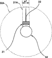
Fig. 2 is the axonometric chart of the probe 20a top ends of ultrasonic endoscope 20.Shown in scanning plane 31A, scan in the CLA scan oscillator group 31 fans pair face parallel with the probe axle.That is, each oscillator 31a of formation CLA scan oscillator group 31 becomes circular-arc arrangement.On the other hand, shown in scanning plane 32A, ELR scan oscillator group 32 is circularly to scanning in the face vertical with the probe axle.That is, each oscillator 32a of formation ELR scan oscillator group 32 becomes circle-shaped arrangement.In addition, for example, the biopsy pin 22 that is used for the collection cell sample punctures along CLA scanning plane 31A.
Fig. 3 A is the front view of the probe 20a top ends of present embodiment, and Fig. 3 B is side view.Shown in Fig. 3 A and Fig. 3 B, CLA scanning plane 31A and ELR scanning plane 32A are mutually orthogonal.In addition, scanning plane 31A and scanning plane 32A have the degree of depth suitable with w2 with the width w1 of each oscillator.
Fig. 4 A represents the sectional view of the ELR scan oscillator group's 32 that present embodiment is related sound ray, and Fig. 4 B represents the sectional view of CLA scan oscillator group 31 sound ray.32 one-tenth circle-shaped arrangement k of ELR scan oscillator group
ELRIndividual each oscillator 32a, establishing M oscillator is 32a (M), with 32L (M) expression centered by oscillator 32a (M) and the sound ray that sends.Similarly, 31 one-tenth circular-arc arrangement k of CLA scan oscillator group
CLAIndividual each oscillator 31a, establishing N oscillator is 31a (N), with 31L (N) expression centered by oscillator 31a (N) and the sound ray that sends.
And in the present embodiment, CLA scan oscillator group 31 radius of curvature r1 is identical with ELR scan oscillator group 32 radius of curvature r2.
Therefore, among CLA scan oscillator group 31 and the ELR scan oscillator group 32, the hyperacoustic relative sending direction of each oscillator is identical.That is, the relation of the ultrasound wave sending direction of the ultrasound wave sending direction of certain oscillator and the oscillator adjacent with this oscillator is fixed.
In addition, in the present embodiment, the arrangement pitches θ p2 of the arrangement pitches θ p1 of each oscillator 31a of CLA scan oscillator group 31 and each oscillator 32a of ELR scan oscillator group 32 is identical.
Fig. 5 A is the related ELR scan oscillator group's 32 of expression present embodiment the synthetic sectional view of sound ray, and Fig. 5 B is expression CLA scan oscillator group 31 the synthetic sectional view of sound ray.At this, be made as along the R direction shown in Fig. 5 A and Fig. 5 B mobile and carry out the hyperacoustic of oscillator and send and receive in turn.
Part in a plurality of oscillators adjacent in a plurality of oscillators of arranging is applied the high voltage pulse with the retardation after adjusting respectively, the skew regularly that applies by high voltage pulse, send respectively the ultrasound wave of the impulse train ripple with the phase place after the adjustment from these a plurality of oscillators, form a sound ray by the mutual stack between the different ultrasound wave of these phase places.Like this, in sound ray forms, not to use respectively a plurality of oscillators but in turn jointly use.
For example, carry out following control: when J oscillator sends, make (J-1) individual oscillator of adjacency carry out a little earlier weak transmission than J oscillator, make (J+1) individual oscillator carry out slightly later on weak transmission than J oscillator.Being that sound ray is synthetic for the data of carrying out this control uses data, is stored in the sound ray synthetic table.
In Fig. 5 A, from the sound ray 32L (M-1) of oscillator 32a (M-1) and synthetic with the sound ray from 32a (M) from the sound ray 32L (M+1) of 32a (M+1), forming focus is the sound ray 32L (M) of Q.Similarly, in Fig. 5 B, from the sound ray 31L (M-1) of oscillator 31a (M-1) and synthetic with the sound ray from 31a (M) from the sound ray 31L (M+1) of 31a (M+1), forming focus is the sound ray 31L (M) of Q.
Then, be sent to the inner ultrasound wave of subject (not shown) and advance in subject inside on one side in the each point generation reflection of subject inside on one side, the ultrasound wave that reflection occurs the each point in subject inside receives and is converted into the reception signal by the part in a plurality of adjacent vibration generators of arrangement.These are received retardations and mutually stack after signals relatively postpone respectively to adjust, form thus the frame signal of the reception sound ray that expression extends along sound ray in subject.That is, in Fig. 5 A and Fig. 5 B, when receiving hyperacoustic echo, three received reception signals of adjacent vibration generators are synthesized to obtain a frame signal.
Then, scan Yi Bian the oscillator one edge R direction that sends and receives is moved in turn, can obtain thus the ultrasonography along scanning plane.
Fig. 6 represents to be presented at the display case of the ultrasonography in the display device 60 of present embodiment.In Fig. 6, in display frame 60, show simultaneously the ultrasonography 60b that ultrasonography 60a that ELR scan oscillator group 32 scanning obtains and CLA scan oscillator group 31 scannings obtain.Therefore, the operation teacher can diagnose according to two images.In addition, also can make in the display frame 60 the regional 60c that has the conditions for diagnostics that shows the diagnostic equipment etc.
Fig. 7 and Fig. 8 are the flow charts of scanning step of each oscillator of the expression oscillator group that consists of present embodiment.Fig. 7 and Fig. 8 have by k
CLAThe CLA scan oscillator group 31 that individual oscillator 31a consists of and by k
ELRThe example of the ELR scan oscillator group's 32 that individual oscillator 32a consists of diagnostic ultrasound equipment.
In scanning step shown in Figure 7, at whole k
CLAAfter the scanning and demonstration end of individual CLA scanning plane oscillator 31a to whole CLA scanning plane, carry out whole k
ELRIndividual ELR scanning plane oscillator 32a is to scanning and the demonstration of whole ELR scanning plane.Then, repeat the scanning of whole CLA scanning plane and scanning and the demonstration of demonstration and whole ELR scanning plane.
That is, when when beginning scanning, at first the setting value N of the oscillator selecting to scan initialized (S1) from CLA face scan oscillator 31a.Then, carry out the action that sends and receives of adjacent three oscillator 31a (N-1), 31a (N) and 31a (N+1), in display device, show the image (S2) of a frame.Use the control data that are stored in the sound ray synthetic table 43 in the control when this sends and receives action.
Then, in order to obtain the next frame image with identical CLA scan oscillator group 31, N adds 1 (S4) in setting value.Then, carry out the scanning of next CLA face scan oscillator 31a.Until the terminal oscillator 31a (k of oscillator group 31
CLA-1) moment (S3) that processing finishes is namely in the moment of the end of scan of whole CLA scanning plane, the scanning of beginning ELR scanning plane.
In the scanning of ELR scanning plane, also be at first the setting value M of the oscillator selecting to scan from ELR face oscillator 32a to be initialized (S5).Then, carry out the action that sends and receives of adjacent three oscillator 32a (M-1), 32a (M) and 32a (M+1), in display device, show the image (S6) of a frame.Control data when in this sends and receives the control in when action, also using the scanning that is stored in the CLA scanning plane in the identical sound ray synthetic table 43.
Then, in order to obtain the next frame image with identical ELR scan oscillator group 32, M adds 1 (S8) in setting value.Then, carry out the scanning of next ELR face scan oscillator 32a.Until the terminal oscillator 32a (k of oscillator group 32
ELR) moment (S7) of finishing of processing, namely in the moment of the end of scan of whole ELR scanning plane, if not from operation teacher's end indication (S9), just restart the scanning of CLA scanning plane.Then, repeat the action that begins from S1.
Relative therewith, in the scanning step of oscillator group shown in Figure 8, using k
CLA31a (N-1), 31a (N) among the individual CLA scanning plane oscillator 31a and these three oscillators of 31a (N+1) use k after carrying out the scanning and demonstration of sound ray 31L (N)
ELR32a (M-1), 32a (M) among the individual ELR scanning plane oscillator 32a and these three oscillators of 32a (M+1) carry out scanning and the demonstration of sound ray 32L (M).Then, continue to carry out in order the scanning of sound ray 31L (N+1) and scanning and the demonstration of demonstration and sound ray 32L (M+1).
That is, when when beginning scanning, at first setting value N and the M of the oscillator selecting to scan are initialized (S11).Then, carry out the action that sends and receives of CLA scan oscillator group 31 adjacent three oscillator 31a (N-1), 31a (N) and 31a (N+1), in display device, show the image (S12) of a frame.In the control when this sends and receives action, use the control data that are stored in the sound ray synthetic table 43.If the oscillator 31a that has carried out scanning and shown is not the oscillator 31a (k of CLA oscillator group 31 ends
CLA-1) (S13), then adds 1 (S15) at setting value N, be oscillator 31a (k
CLA-1) in the situation (S13), N is initialized (S14) and prepares ensuing scanning and demonstration.
Then, carry out the action that sends and receives of ELR scan oscillator group 32 adjacent three oscillator 32a (M-1), 32a (M) and 32a (M+1), in display device, show the image (S16) of a frame.Send and receive in the control in when action the control data when also using the scanning that is stored in the CLA scanning plane in the identical sound ray synthetic table 43 at this.If the oscillator 32a that has carried out scanning and shown is not the oscillator 32a (k of ELR oscillator group 32 ends
ELR) (S17), then add 1 (S19) at setting value M, be oscillator 31a (k
ELR) situation under (S17), M is initialized (S18) and prepares ensuing scanning and demonstration.Then, repeat the action that begins from S12, finish indication (S20) until send from the operation teacher.
In the scanning step shown in the flow chart of Fig. 8, each frame signal in frame signal of each that is obtained by CLA scan oscillator group 31 or ELR scan oscillator group 32 is shown as new frame in display device 60.That is, in the diagnostic ultrasound equipment of the scanning step shown in the flow chart of use Fig. 8, the scanning of a plurality of oscillator groups is switched the oscillator group that scans behind sound ray of each scanning.Therefore, compare with the diagnostic ultrasound equipment that uses scanning step shown in Figure 7, the CLA scanning plane shows that 60b and ELR scanning plane show that the time migration between the 60a disappears, and can show more real-time image to the operation teacher.
In addition, CLA scan oscillator group 31 terminal oscillator 31a (1) is use in sound ray 31L (2) synthetic only, and does not send sound ray 31L (1).Similarly, CLA scan oscillator group 31 other end oscillator 31a (k
CLA) only at sound ray 31L (k
CLA-1) synthetic middle the use, and do not send sound ray 31L (k
CLA).Relative therewith, ELR scan oscillator group 32 sound ray 32L (1) is by oscillator 32a (k
ELR), 32a (1) and these three oscillators of 32a (2) are synthetic, similarly, sound ray 32L (k
ELR) by oscillator 32a (k
ELR-1), 32a (k
ELR) and these three oscillators of 32a (1) synthetic.
Therefore, in the flow chart of Fig. 7 and Fig. 8, the initial value of the setting value N during CLA scanning is 2, and the oscillator 31 that sends terminal sound ray of the CLA scan oscillator group 31 is oscillator 31a (k
CLA-1), relative therewith, the initial value of the setting value M during ELR scanning is that 1, ELR scan oscillator group 32 last oscillator 32 becomes oscillator 32a (k
ELR).
For the coordination by a plurality of oscillators as described above obtains a sound ray and frame data, must obtain in advance the control data of parameter of processing be used to the drive control data that sends and receives with to the data that receive etc., and store in the sound ray synthetic table.In order to make a plurality of oscillator groups jointly use this sound ray synthetic table, need each oscillator the sound ray direction, be that relative ultrasound wave sending direction is consistent between each oscillator group, in other words, the radius of curvature that shares the oscillator group of sound ray synthetic table must be identical.If not the oscillator group of this specific combination, just can't use common sound ray synthetic table, can't switch oscillator group by switching part and carry out common use.
And, be preferably each oscillator of shared oscillator group configuration space, be that spacing θ p1 is also consistent with spacing θ p2.
In addition, in the above-described embodiment, show the example that utilizes three adjacent oscillators to synthesize a sound ray, but also can utilize the oscillator of the number that surpasses three to synthesize a sound ray.In addition, by using the control of virtual sound ray, can not only send sound ray from the two ends oscillator of CLA oscillator group, even the different oscillator group of spacing θ p also can be used common sound ray synthetic table.
In the above-described embodiment, with use a radial pattern oscillator group and convex-surface type oscillator group, namely, use the example of two oscillator groups to describe, but also can switch a plurality of oscillator groups of use more than three.Fig. 9 A~Fig. 9 C, Figure 10 A~Figure 10 C and Figure 11 A~Figure 11 C are expression has the diagnostic ultrasound equipment of a plurality of oscillator groups that scan in mutually orthogonal face the figure of scanning plane, Fig. 9 A, Figure 10 A and Figure 11 A are respectively the front views of observing from the direction vertical with respect to endoscope's length direction, Fig. 9 B, Figure 10 B and Figure 11 B are respectively the top views of observing from above with respect to endoscope's length direction, and Fig. 9 C, Figure 10 C and Figure 11 C are respectively the side views of observing from the side with respect to endoscope's length direction.
Fig. 9 A~Fig. 9 C is identical with above-mentioned embodiment, be with a radial pattern oscillator group and convex-surface type oscillator group, namely, scan the example of two face A1 and A2 with two oscillator groups.Relative therewith, Figure 10 A~Figure 10 C be with a radial pattern oscillator group and two convex-surface type oscillator groups, namely, scan the example of three face A1, A2 and A3 with three oscillator groups, Figure 11 A~Figure 11 C illustrates with a radial pattern oscillator group and four convex-surface type oscillator groups, namely, scan the example of five face A1, A2, A3, A4 and A5 with five oscillator groups.In addition, even the oscillator group number is the embodiment more than three, its basic structure is that two the embodiment of situation is identical with the oscillator group number also.
A kind of diagnostic ultrasound equipment has been described, in the diagnostic ultrasound equipment of the oscillator group of using a plurality of electronic type scan modes, use has by the probe that is arranged in the oscillator group that circumference with same curvature radius or circular-arc a plurality of oscillators consist of, can share the sound ray synthetic table thus, and changeable and use one group to send and receive section, image production part etc.
But, the related diagnostic ultrasound equipment of embodiments of the present invention also has following advantage, it possesses many groups and sends and receives section and image production part etc., send and receive in the situation that section or image production part etc. break down at one group thus, send and receive section and image production part etc. and also can continue to use by switching to other that do not break down.Especially in the situation of using three above oscillator groups, one group of processing speed when sending and receiving section, image production part etc. is slack-off sometimes when sharing, and is preferably to possess many groups and send and receive section, image production part etc.
Then, the different related diagnostic ultrasound equipment of embodiment of the present invention is described.In the related diagnostic ultrasound equipment of present embodiment, the oscillator group that scans is switched in the scanning of a plurality of oscillator groups according to predefined order.Namely, in the diagnostic ultrasound equipment that has illustrated, for example in the scanning sequency shown in the scanning process figure of each oscillator of the formation oscillator group of Fig. 7, the moment at the end of scan of whole CLA scanning plane begins the scanning of ELR scanning plane, begins the scanning of CLA scanning plane in the moment of the end of scan of whole ELR scanning plane.That is, switch the oscillator group that scans in the moment of the end of scan of the whole scanning plane of each oscillator group.In addition, in the diagnostic ultrasound equipment that has illustrated, for example in the scanning sequency shown in the scanning process figure of each oscillator of the formation oscillator group of Fig. 8, to by each frame signal in each frame signal of CLA scan oscillator group 31 or ELR scan oscillator group 32 scannings, all switch the oscillator group that scans.
Relative therewith, in the related diagnostic ultrasound equipment of different embodiment of the present invention, switch the oscillator group that scans according to predefined order.In addition, the scanogram that shows in display device 60 also can only be the image that has carried out the oscillator group of scanning.
Below, use Figure 12 that the flow process of the processing of the diagnostic ultrasound equipment that present embodiment is related is described.Figure 12 is the flow chart for the flow process of the processing of the related diagnostic ultrasound equipment of explanation present embodiment.
In the diagnostic ultrasound equipment of present embodiment, when being connected to ultrasonic endoscope 20 on the control device 40, control device 40 judges that whether endoscope probe that the ultrasonic endoscope 20 that connects has a plurality of oscillator groups is plane type probe (step S31) for example.Be common probe, namely be only to have in the situation of probe of an oscillator group at the probe that connects, in step S31, be judged as No, carry out in order the processing that begins from following step S32.
Relative therewith, in step S31, be judged as in the situation of Yes, further judge the detailed kind (step S38) of the probe that connects.Then, distinguish the pattern that can scan with the probe that connects, (step S39) such as radial pattern, convex surface pattern or linear model.
Then, in step 40, with scan pattern, namely first-class in display device 70 for the selection picture disply that presets the oscillator group that scans from a plurality of oscillator groups.In addition, in selecting picture, can set the oscillator group that scans, scanning sequency, scanning switching timing (time) etc.According to select operation's teacher of picture scan pattern to set indication from this, control circuit 40 switches the oscillator group that scans according to predefined sequential scheduling.
In addition, in step 40, from a plurality of oscillator groups, only selecting in step S41, to be judged as Yes in the situation of an oscillator group, carry out in order the processing that begins from following step S42.
Relative therewith, in step S41, be judged as in the situation of No, according to predefined sequential scheduling in step S40, set to be used for switch the combination (step S47) of the oscillator group that scans, that sets an oscillator group at first scanning by control device 40 sends and receives control (step S48).Obtaining with image of the transmitting and receiving data of an oscillator group that then, at first scans generates (step S49).Then, 40 pairs of control device are set to an oscillator group of carrying out next one scanning and send and receive obtaining of control setting (step S50) and transmitting and receiving data and image generation (step S51), and carry out image demonstration (step S45).
Then, in any scanning, proceed to scan until end of scan indication etc. from the operation teacher is arranged.
In the diagnostic ultrasound equipment of present embodiment, can switch with the scanning that presets a plurality of oscillator groups with performing the operation Shi Xiwang.Therefore, the diagnostic ultrasound equipment of present embodiment has more been optimized operability outside having the effect that above-mentioned diagnostic ultrasound equipment involved in the present invention has.
The preferred embodiments of the present invention have been described with reference to the accompanying drawings.Should be appreciated that the present invention is not limited only to the above embodiments, those skilled in the art can carry out various changes or modification in the situation that does not deviate from the spirit or scope of the present invention that limits such as appended claims.
Claims (10)
1. diagnostic ultrasound equipment comprises:
The first oscillator group is by the top ends that is arranged on probe, be arranged in circle-shaped a plurality of oscillators and consist of;
The second oscillator group is made of the circular-arc a plurality of oscillators that are arranged in radius of curvature identical with above-mentioned the first oscillator group; And
The sound ray synthetic table that shares, the control data of above-mentioned each oscillator group of its storage;
Wherein, the arrangement pitches of the above-mentioned oscillator of above-mentioned the first oscillator group is identical with the arrangement pitches of the above-mentioned oscillator of above-mentioned the second oscillator group, and above-mentioned the first oscillator group and above-mentioned the second oscillator group scan in mutually orthogonal face.
2. diagnostic ultrasound equipment according to claim 1 is characterized in that,
Comprise display part, this display part has the display frame that can show simultaneously a plurality of ultrasonographies,
On above-mentioned display part, show simultaneously a plurality of ultrasonographies that obtained by above-mentioned the first oscillator group and the scanning of above-mentioned the second oscillator group.
3. diagnostic ultrasound equipment according to claim 1 is characterized in that,
The oscillator group that scans is switched in the scanning of above-mentioned the first oscillator group and above-mentioned the second oscillator group according to predefined order.
4. diagnostic ultrasound equipment according to claim 1 is characterized in that,
Sound ray of the every scanning of the scanning of above-mentioned the first oscillator group and above-mentioned the second oscillator group just switches the oscillator group that scans.
5. diagnostic ultrasound equipment according to claim 1 is characterized in that,
The above-mentioned oscillator of above-mentioned the second oscillator group is configured on the length direction of above-mentioned probe.
6. diagnostic ultrasound equipment comprises:
Elongated probe;
ELR scan oscillator group and CLA scan oscillator group, by the top ends that is arranged on above-mentioned probe, be arranged in circle-shaped ELR scanning plane oscillator and be arranged in circular-arc CLA scanning plane oscillator and consist of, in mutually orthogonal face, scan, wherein, ELR scan oscillator group has identical radius of curvature with CLA scan oscillator group, and the arrangement pitches of above-mentioned ELR scan oscillator group's above-mentioned ELR scanning plane oscillator is identical with the arrangement pitches of above-mentioned CLA scan oscillator group's above-mentioned CLA scanning plane oscillator; And
The sound ray synthetic table that shares, it stores above-mentioned ELR scan oscillator group and above-mentioned CLA scan oscillator group's control data.
7. diagnostic ultrasound equipment according to claim 6 is characterized in that,
Comprise display part, this display part has the display frame that can show simultaneously two ultrasonographies,
In above-mentioned display part, show simultaneously two ultrasonographies that obtained by above-mentioned ELR scan oscillator group and above-mentioned CLA scan oscillator group scan.
8. diagnostic ultrasound equipment according to claim 6 is characterized in that,
The oscillator group that scans is switched in above-mentioned ELR scan oscillator group's scanning and above-mentioned CLA scan oscillator group's scanning according to predefined order.
9. diagnostic ultrasound equipment according to claim 6 is characterized in that,
Sound ray of the every scanning of above-mentioned ELR scan oscillator group's scanning and above-mentioned CLA scan oscillator group's scanning just switches the oscillator group that scans.
10. diagnostic ultrasound equipment according to claim 6 is characterized in that,
Above-mentioned CLA scan oscillator group's above-mentioned CLA scanning plane oscillator is configured on the length direction of above-mentioned probe.
Applications Claiming Priority (3)
| Application Number | Priority Date | Filing Date | Title |
|---|---|---|---|
| JP2007245785 | 2007-09-21 | ||
| JP2007-245785 | 2007-09-21 | ||
| JP2007245785A JP5085250B2 (en) | 2007-09-21 | 2007-09-21 | Ultrasonic diagnostic equipment |
Publications (2)
| Publication Number | Publication Date |
|---|---|
| CN101390760A CN101390760A (en) | 2009-03-25 |
| CN101390760B true CN101390760B (en) | 2013-05-01 |
Family
ID=39941908
Family Applications (2)
| Application Number | Title | Priority Date | Filing Date |
|---|---|---|---|
| CNU2008201344957U Expired - Fee Related CN201316278Y (en) | 2007-09-21 | 2008-08-21 | Ultrasonic wave diagnostic device |
| CN2008101472131A Active CN101390760B (en) | 2007-09-21 | 2008-08-21 | Ultrasound diagnostic apparatus |
Family Applications Before (1)
| Application Number | Title | Priority Date | Filing Date |
|---|---|---|---|
| CNU2008201344957U Expired - Fee Related CN201316278Y (en) | 2007-09-21 | 2008-08-21 | Ultrasonic wave diagnostic device |
Country Status (5)
| Country | Link |
|---|---|
| US (1) | US20090082674A1 (en) |
| EP (1) | EP2039297B9 (en) |
| JP (1) | JP5085250B2 (en) |
| KR (1) | KR20090031269A (en) |
| CN (2) | CN201316278Y (en) |
Families Citing this family (10)
| Publication number | Priority date | Publication date | Assignee | Title |
|---|---|---|---|---|
| CN102090917A (en) * | 2011-03-10 | 2011-06-15 | 苏州中加医疗科技有限公司 | Dual-plane probe for puncture location |
| JP5976441B2 (en) * | 2011-08-03 | 2016-08-23 | 東芝メディカルシステムズ株式会社 | Ultrasonic probe and ultrasonic diagnostic apparatus |
| CN103750863B (en) * | 2014-01-07 | 2017-07-18 | 绵阳美科电子设备有限责任公司 | A kind of ultrasound volume measuring probe and its measuring method |
| JP6001230B2 (en) * | 2014-08-18 | 2016-10-05 | オリンパス株式会社 | Ultrasound endoscope, ultrasound observation apparatus, and ultrasound endoscope system |
| CN104523293B (en) * | 2014-12-30 | 2017-07-14 | 中国人民解放军第三军医大学第三附属医院 | The dynamic Small object monitoring imaging device of arc micro scanning ultrasound |
| CN107495987A (en) * | 2017-08-14 | 2017-12-22 | 苏州斯科特医学影像科技有限公司 | A kind of visible abortion biplane detection device |
| WO2020118709A1 (en) * | 2018-12-14 | 2020-06-18 | 深圳先进技术研究院 | Ultrasonic endoscope system |
| KR102324390B1 (en) * | 2019-08-27 | 2021-11-11 | 주식회사 힐세리온 | Portable Hybrid Ultrasonic Diagnostic Apparatus |
| CN113768538A (en) * | 2021-09-15 | 2021-12-10 | 上海益超医疗器械有限公司 | Detection control method, device and system for biplane ultrasonic probe device |
| CN118252543B (en) * | 2024-05-29 | 2024-09-10 | 武汉楚精灵医疗科技有限公司 | Image processing program switching method and device |
Citations (5)
| Publication number | Priority date | Publication date | Assignee | Title |
|---|---|---|---|---|
| EP0139574A2 (en) * | 1983-09-29 | 1985-05-02 | Bruno Denis Lucien Fornage | Ultrasonic probe for body tracts |
| US5186176A (en) * | 1990-04-11 | 1993-02-16 | Kabushiki Kaisha Toshiba | Ultrasonic diagnosis apparatus |
| US6045508A (en) * | 1997-02-27 | 2000-04-04 | Acuson Corporation | Ultrasonic probe, system and method for two-dimensional imaging or three-dimensional reconstruction |
| US6511427B1 (en) * | 2000-03-10 | 2003-01-28 | Acuson Corporation | System and method for assessing body-tissue properties using a medical ultrasound transducer probe with a body-tissue parameter measurement mechanism |
| WO2004064614A2 (en) * | 2003-01-23 | 2004-08-05 | 3G Ultrasound, Inc. | Ultrasonic imaging device, system and method of use |
Family Cites Families (14)
| Publication number | Priority date | Publication date | Assignee | Title |
|---|---|---|---|---|
| JPS62152441A (en) * | 1985-12-26 | 1987-07-07 | 株式会社東芝 | Body cavity ultrasonic probe |
| JPS62227327A (en) * | 1986-03-28 | 1987-10-06 | 株式会社東芝 | Ultrasonic probe |
| GB2212267B (en) * | 1987-11-11 | 1992-07-29 | Circulation Res Ltd | Methods and apparatus for the examination and treatment of internal organs |
| JPH03182238A (en) * | 1989-12-13 | 1991-08-08 | Toshiba Corp | Ultrasonic probe and ultrasonic diagnosing device for body cavity |
| JPH05140A (en) * | 1991-06-24 | 1993-01-08 | Matsushita Electric Ind Co Ltd | Ultrasonic probe and ultrasonic diagnosing apparatus |
| US5186177A (en) * | 1991-12-05 | 1993-02-16 | General Electric Company | Method and apparatus for applying synthetic aperture focusing techniques to a catheter based system for high frequency ultrasound imaging of small vessels |
| US5471988A (en) * | 1993-12-24 | 1995-12-05 | Olympus Optical Co., Ltd. | Ultrasonic diagnosis and therapy system in which focusing point of therapeutic ultrasonic wave is locked at predetermined position within observation ultrasonic scanning range |
| JPH09154843A (en) * | 1995-12-11 | 1997-06-17 | Aloka Co Ltd | Ultrasonic diagnostic device |
| JP3862793B2 (en) * | 1996-11-19 | 2006-12-27 | 株式会社日立メディコ | Ultrasonic probe and ultrasonic diagnostic apparatus using the same |
| US5876345A (en) * | 1997-02-27 | 1999-03-02 | Acuson Corporation | Ultrasonic catheter, system and method for two dimensional imaging or three-dimensional reconstruction |
| JPH1176242A (en) * | 1997-09-11 | 1999-03-23 | Matsushita Electric Ind Co Ltd | Ultrasonic probe in body cavity |
| US7066887B2 (en) * | 2003-10-21 | 2006-06-27 | Vermon | Bi-plane ultrasonic probe |
| JP4488288B2 (en) * | 2003-12-10 | 2010-06-23 | オリンパス株式会社 | Ultrasound diagnostic imaging equipment |
| JP4381344B2 (en) * | 2005-05-17 | 2009-12-09 | ジーイー・メディカル・システムズ・グローバル・テクノロジー・カンパニー・エルエルシー | Ultrasonic diagnostic equipment |
-
2007
- 2007-09-21 JP JP2007245785A patent/JP5085250B2/en active Active
-
2008
- 2008-08-21 CN CNU2008201344957U patent/CN201316278Y/en not_active Expired - Fee Related
- 2008-08-21 CN CN2008101472131A patent/CN101390760B/en active Active
- 2008-09-18 EP EP08016453.6A patent/EP2039297B9/en not_active Not-in-force
- 2008-09-19 KR KR1020080091851A patent/KR20090031269A/en not_active Application Discontinuation
- 2008-09-19 US US12/234,123 patent/US20090082674A1/en not_active Abandoned
Patent Citations (5)
| Publication number | Priority date | Publication date | Assignee | Title |
|---|---|---|---|---|
| EP0139574A2 (en) * | 1983-09-29 | 1985-05-02 | Bruno Denis Lucien Fornage | Ultrasonic probe for body tracts |
| US5186176A (en) * | 1990-04-11 | 1993-02-16 | Kabushiki Kaisha Toshiba | Ultrasonic diagnosis apparatus |
| US6045508A (en) * | 1997-02-27 | 2000-04-04 | Acuson Corporation | Ultrasonic probe, system and method for two-dimensional imaging or three-dimensional reconstruction |
| US6511427B1 (en) * | 2000-03-10 | 2003-01-28 | Acuson Corporation | System and method for assessing body-tissue properties using a medical ultrasound transducer probe with a body-tissue parameter measurement mechanism |
| WO2004064614A2 (en) * | 2003-01-23 | 2004-08-05 | 3G Ultrasound, Inc. | Ultrasonic imaging device, system and method of use |
Also Published As
| Publication number | Publication date |
|---|---|
| CN101390760A (en) | 2009-03-25 |
| KR20090031269A (en) | 2009-03-25 |
| JP2009072447A (en) | 2009-04-09 |
| EP2039297B1 (en) | 2016-11-23 |
| CN201316278Y (en) | 2009-09-30 |
| EP2039297A1 (en) | 2009-03-25 |
| EP2039297B9 (en) | 2017-03-29 |
| US20090082674A1 (en) | 2009-03-26 |
| JP5085250B2 (en) | 2012-11-28 |
Similar Documents
| Publication | Publication Date | Title |
|---|---|---|
| CN101390760B (en) | Ultrasound diagnostic apparatus | |
| EP1745745B1 (en) | Apparatus for obtaining ultrasonic images and method of obtaining ultrasonic images | |
| US20070232924A1 (en) | Ultrasonic probe and ultrasonic diagnosing apparatus | |
| US20090069679A1 (en) | Ultrasound diagnostic apparatus | |
| CN103702615A (en) | Ultrasound probe and ultrasound diagnostic device | |
| EP3742975B1 (en) | Ultrasound imaging apparatus and method | |
| CN102090901A (en) | Medical image display apparatus | |
| JP2007068918A (en) | Ultrasonic probe and ultrasonic diagnosis apparatus | |
| US20090156935A1 (en) | Three Dimensional Diagnostic Ultrasound Imaging System with Image Reversal and Inversion | |
| US20090149757A1 (en) | Three Dimensional Ultrasonic Scanning With Live Subvolumes | |
| JP4266611B2 (en) | Ultrasonic probe, ultrasonic endoscope, and ultrasonic diagnostic apparatus | |
| US7632233B2 (en) | Ultrasonic endoscope and ultrasonic endoscopic apparatus | |
| JP4488288B2 (en) | Ultrasound diagnostic imaging equipment | |
| US20090030313A1 (en) | Three Dimensional Diagnostic Ultrasonic Image Display | |
| JPH09135498A (en) | Ultrasonic oscillator element | |
| JP2002177278A (en) | Ultrasonic diagnostic device | |
| WO2003001240A1 (en) | Ultrasonic diagnostic system for selectively developing ultrasound diagnostic data | |
| JPH07136171A (en) | Ultrasonic diagnostic system | |
| JP2005168766A (en) | Ultrasonic probe | |
| US7691065B2 (en) | Ultrasonic probe and ultrasonic diagnostic device | |
| JPH04256739A (en) | Ultrasonic diagnostic device | |
| JPS624984B2 (en) | ||
| JPH04183455A (en) | Vibration piece array for ultrasonic body cavity probe | |
| JPH0288047A (en) | Electronic scanning type ultrasonic tomography device | |
| JPH03277353A (en) | Ultrasonic diagnostic device |
Legal Events
| Date | Code | Title | Description |
|---|---|---|---|
| C06 | Publication | ||
| PB01 | Publication | ||
| C10 | Entry into substantive examination | ||
| SE01 | Entry into force of request for substantive examination | ||
| C14 | Grant of patent or utility model | ||
| GR01 | Patent grant | ||
| C41 | Transfer of patent application or patent right or utility model | ||
| TR01 | Transfer of patent right |
Effective date of registration: 20151126 Address after: Tokyo, Japan, Japan Patentee after: Olympus Corporation Address before: Tokyo, Japan, Japan Patentee before: Olympus Medical Systems Corp. |