This is firmware for T12 soldering stations with the MM32SPIN27 Arm processor. These are user notes. For developers' notes, see README_DEVELOPER.
The soldering station has four states: running, boost, standby and sleeping.
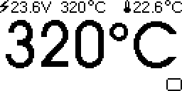
When running, the top line of the display shows power supply voltage, setpoint temperature, and cold junction (ambient) temperature. The middle of the display shows soldering iron tip temperature. The bottom of the display shows a bar graph of applied heating power.
The soldering station has a rotary encoder with pushbutton. Turning the knob changes setpoint temperature in steps (default: steps of 5°C). For fine adjustments in steps of 1°C first turn the knob, then push while turning. The setpoint is displayed in inverted color.
When running, a short click of the knob will switch to boost mode. In boost mode, setpoint temperature is increased for a short time. (default: increase of 50°C for 5 minutes)
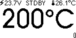
If the soldering station is inactive, after some time the soldering station goes in standby. (default: 20 minutes of inactivity, standby temperature 200°C).
If the soldering station is inactive even longer, the soldering station goes into sleep mode. (default: 30 minutes of inactivity, heating switched off).
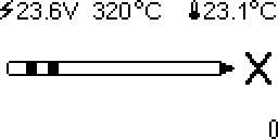
If no T12 tip is detected, a T12 soldering tip is shown.
A short click will switch the soldering station from running ⇨ boost ⇨ standby ⇨ sleep ⇨ running.
A long press - a second or more - will switch to the menu. The menu allows changing and saving default values.
Here is a video of the soldering station powering up.
When changed, the temperature setpoint is saved automatically within 30 seconds. When the soldering station is switched on, the temperature goes back to what it was before the station was switched off.
Other settings have to be saved manually. Go to the "Settings" menu, and choose "Store". Settings are saved in flash, and overwritten when you install new firmware.
The soldering iron tip contains a thermocouple. The thermocouple gives the temperature difference between soldering iron tip and soldering iron handle. To know the temperature of the soldering iron tip, one has to add the temperature of the soldering iron handle (the cold junction temperature) and the temperature given by the thermocouple.
To measure the temperature in the soldering iron handle, three sensors are available: CPU, NTC, and DS18B20.
The microcontroller has an internal temperature sensor. As the microcontroller heats up during operation, the internal temperature of the microcontroller may be different from the temperature of the cold junction.
A separate document, README_NTC, handles configuring the NTC temperature sensor.
Instead of manually calibrating an analogue temperature sensor it is much more convenient to use factory-calibrated digital sensors.
The DS18B20 is a digital one-wire temperature sensor. One-wire refers to the possibility of powering the sensor, and reading the temperature using only one wire.
For best results, put a DS18B20 in the soldering iron handle. This requires opening the soldering iron handle, removing the NTC and installing a DS18B20 temperature sensor.
Inside the soldering iron handle, replace the NTC with a DS18B20. Connect DS18B20 VCC and GND to ground (green wire), connect DS18B20 DIO to the white wire (NTC). Colors may differ.
DS18B20 in soldering iron handle. The DS18B20 has a TO-92 package, like a leaded small-signal transistor. schematic of the handle with and without mod.
To avoid short-circuits, cover everything in Kapton tape. Make sure blank metal does not touch other blank metal. Make sure vibration sensor leads do not make contact with temperature sensor leads.
The DS18B20 data line needs a pull-up resistor. On the PCB, connect the T12 connector pin "J" to pin "F" (pin PB7, UART RX) with a pull-up resistor to 3.3V. Suitable resistor values are 1K - 3.3K. (picture: 2K)
In settings, choose SENSOR ONEWIRE.
When one buys a DS18B20, it is not always clear whether the chip is original or generic. To determine the manufacturer, use the "Check ONEWIRE" menu, and look up the sensor family in this table. Output for the "Made in Asia" DS18B20 I am using:
[1]-Family C SENSYLINK CT1820B
[2] BACK
Compared to a Maxim DS18B20, the CT1820B uses less power (30µA, as long as one does not write to EEPROM), and is faster (30ms). Whatever brand you choose, the DS18B20 has to be able to work in parasitic mode.
If you do not wish to modify the soldering iron handle, you can simply connect a DS18B20 to the pcb pin header. The pin header has ground and 3.3V for the pull-up resistor.
DS18B20 is the default temperature sensor, it's what I use. This can be changed in the menu.
E.g. for DS18B20, in the menu:
- press button more than 1 second to enter menu
- Cold End ⇨ Sensor ⇨ ONEWIRE
- Save and Recall ⇨ Save
To download firmware, connect a debugger probe to the SWD connector:
| Label | Pin | Function |
|---|---|---|
| C | PA14 | SWCLK |
| D | PA13 | SWDIO |
| GND | GND | |
| VCC | 3.3V | |
| D | PB6 | UART TX |
| F | PB7 | UART RX |
Both commercial and open source debuggers can be used to download firmware to MM32SPIN27.
The Segger JLink debugger does not support MM32SPIN27 directly, but configuring as a MM32L072XX works.
JLinkGDBServer -device MM32L072XX -if SWD -speed 1000
Some useful commands are in the doc/scripts directory.
Upon delivery, the flash of the processor is read-protected. When using JLink, the first time firmware is downloaded, type mon flash erase to unlock the device.
 $ arm-none-eabi-gdb
(gdb) tar ext :2331
Remote debugging using :2331
warning: No executable has been specified and target does not support
determining executable automatically.  Try using the "file" command.
0xfffffffe in ?? ()
(gdb) mon reset
Resetting target
(gdb) mon halt
(gdb) mon flash erase
Flash erase: O.K.
(gdb) file ~/Arduino/t12-958/build/SeekFree.mm32.MM32SPIN27/t12-958.ino.elf
Reading symbols from ~/Arduino/t12-958/build/SeekFree.mm32.MM32SPIN27/t12-958.ino.elf...
(No debugging symbols found in ~/Arduino/t12-958/build/SeekFree.mm32.MM32SPIN27/t12-958.ino.elf)
(gdb) lo
Loading section .isr_vector, size 0xc0 lma 0x8000000
Loading section .text, size 0xb8a0 lma 0x80000c0
Loading section .rodata, size 0x31e8 lma 0x800bc00
Loading section .ARM, size 0x8 lma 0x800ede8
Loading section .init_array, size 0x34 lma 0x800edf0
Loading section .fini_array, size 0xc lma 0x800ee24
Loading section .data, size 0xd28 lma 0x800ee30
Start address 0x0800888c, load size 63672
Transfer rate: 10363 KB/sec, 7074 bytes/write.
(gdb) mon reset
Resetting target
(gdb) c
Continuing.
^C
Program received signal SIGTRAP, Trace/breakpoint trap.
0x08003952 in Scheduler::execute() ()
(gdb) q
Remote connection closed
 $
In the above, at the message "continuing", there is a short beep and the display lights up.
The open source Black Magic Probe supports MM32. To download:
 $ /opt/xpack-arm-none-eabi-gcc-10.3.1-2.3/bin/arm-none-eabi-gdb -q
(gdb) tar ext /dev/ttyBmpGdb
Remote debugging using /dev/ttyBmpGdb
(gdb) mon ver
Black Magic Probe (BlackPill-F411CE) 08583c1-dirty, Hardware Version 0
Copyright (C) 2022 Black Magic Debug Project
License GPLv3+: GNU GPL version 3 or later <http://gnu.org/licenses/gpl.html>

(gdb) mon swd
Available Targets:
No. Att Driver
 1      MM32SPIN27 M0
(gdb) at 1
Attaching to Remote target
warning: No executable has been specified and target does not support
determining executable automatically.  Try using the "file" command.
0x0800a5f8 in ?? ()
(gdb) file ~/Arduino/t12-958/build/SeekFree.mm32.MM32SPIN27/t12-958.ino.elf
A program is being debugged already.
Are you sure you want to change the file? (y or n) y
Reading symbols from ~/Arduino/t12-958/build/SeekFree.mm32.MM32SPIN27/t12-958.ino.elf...
(gdb) lo
Loading section .isr_vector, size 0xc0 lma 0x8000000
Loading section .text, size 0xdb4c lma 0x80000c0
Loading section .rodata, size 0x34f8 lma 0x800e000
Loading section .ARM, size 0x8 lma 0x80114f8
Loading section .init_array, size 0x38 lma 0x8011500
Loading section .fini_array, size 0x10 lma 0x8011538
Loading section .data, size 0xde4 lma 0x8011548
Start address 0x0800a660, load size 73528
Transfer rate: 26 KB/sec, 919 bytes/write.
(gdb) compare-sections
Section .isr_vector, range 0x8000000 -- 0x80000c0: matched.
Section .text, range 0x80000c0 -- 0x800dc0c: matched.
Section .rodata, range 0x800e000 -- 0x80114f8: matched.
Section .ARM, range 0x80114f8 -- 0x8011500: matched.
Section .init_array, range 0x8011500 -- 0x8011538: matched.
Section .fini_array, range 0x8011538 -- 0x8011548: matched.
Section .data, range 0x8011548 -- 0x801232c: matched.
(gdb) r
The program being debugged has been started already.
Start it from the beginning? (y or n) y
A note of caution here. I've successfully used Black Magic Probe on a MM32SPIN27 that already had the write protection removed.
What has not been tested is whether Black Magic Probe is able to remove the write protection itself (modifying the option bits with mon option).
Carefully consider risks and consequences of modifying a solder iron. One faulty connection, one wrong line of code and the soldering iron glows red hot. Do not leave a soldering iron unattended.
Copyright (c) 2022 Koen De Vleeschauwer
Permission is hereby granted, free of charge, to any person obtaining a copy of this software and associated documentation files (the "Software"), to deal in the Software without restriction, including without limitation the rights to use, copy, modify, merge, publish, distribute, sublicense, and/or sell copies of the Software, and to permit persons to whom the Software is furnished to do so, subject to the following conditions:
The above copyright notice and this permission notice shall be included in all copies or substantial portions of the Software.
THE SOFTWARE IS PROVIDED "AS IS", WITHOUT WARRANTY OF ANY KIND, EXPRESS OR IMPLIED, INCLUDING BUT NOT LIMITED TO THE WARRANTIES OF MERCHANTABILITY, FITNESS FOR A PARTICULAR PURPOSE AND NONINFRINGEMENT. IN NO EVENT SHALL THE AUTHORS OR COPYRIGHT HOLDERS BE LIABLE FOR ANY CLAIM, DAMAGES OR OTHER LIABILITY, WHETHER IN AN ACTION OF CONTRACT, TORT OR OTHERWISE, ARISING FROM, OUT OF OR IN CONNECTION WITH THE SOFTWARE OR THE USE OR OTHER DEALINGS IN THE SOFTWARE.
This builds upon the work of Jose Barros, DeividAlfa, Dreamcat4 and many others.
not truncated


