Engine Builder and Engine Pro present Shop Solutions in each issue of Engine Builder Magazine and at enginebuildermag.com to provide machine shop owners and engine builders the opportunity to share their knowledge to benefit the entire industry and their own shops. Those who submit Shop Solutions that are published are awarded either a prepaid $100 Visa gift card or a shop stool. Submit your Shop Solution at [email protected]. You must include your name, shop name, shop address and shop telephone number. Submitted Shop Solutions not published will be kept on file and reevaluated for each month’s new entries.
MAGNETIC HOOKS
I use magnetic hooks around the shop to organize and hang small items. They do work great in the hone cabinet, and I don’t need to wash the gaskets every time. A pack of 20 hooks cost around $10.

Randy Torvinen
Torvinen’s Machine
Menahga, MN
CRANK MAT
Typically, most places that grind crankshafts store them on end before and after grinding, but that gets to be difficult when they have pins in the flange. We found that an anti-fatigue mat with holes in it works perfectly to keep them upright.

Adney Brown
Performance Crankshaft inc.
Ferndale, MI
QUICK STROKE CHECK
If you’re taking an engine apart and are unsure of the cubic inch or the crank stroke, here is a quick way to figure it out. Simply rotate the engine until one piston is at BDC. Take a measurement from the deck of your block down to the deck of the piston. You can use a tape measure or a machinist scale. This will be the stroke of the crankshaft.

Nick Jones
Automotive Machine
Fraser, MI
DON’T GET INTO A BIND
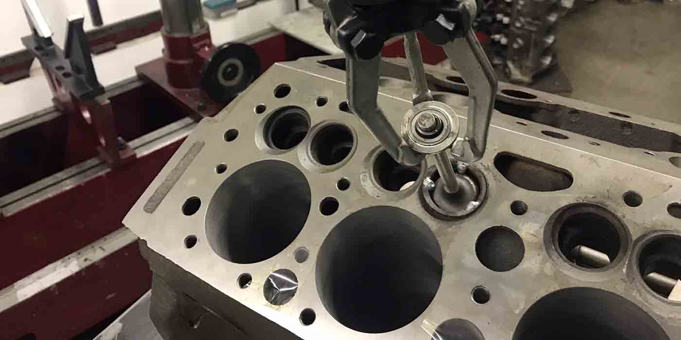
When valve train clearances are going to be tight, I like to double check my measurements and bench calculations by actually testing the components after they’re assembled. I put the valves and springs in this head, then used my quill on the seat & guide machine to check that my math was correct. I touched off on the valve tip, zeroed the indicator, opened the valve to full lift, and recorded how much further I could open the valve before it hit coil bind. I like to have at least two methods of measurements on anything that is critical, or that could cause a failure point. In this case, I actually measured .010” more clearance to coil bind than I had calculated on the bench.

Jake Sampson
Sampson Race Engines
Inver Grove Heights, MN
ROD STRAIGHTENING
When checking and correcting rod straightness, I use two bars against each other in the rod vice. Since the vice isn’t mounted to the cabinet strong enough for most correction work, this allows you to use it. I feel the two bars gives me a better feel for how much I’m correcting, as I’m not fighting the vice flexing. I prefer this to putting the rod vice in a bench vice.

Ron Flood
Cedar Machine
North Branch, MN
RELOCATING TIMING MARKS
Timing marks on pulleys can be relocated by using the following formula – C = Pulley Diameter x 0.00873 x #°
where: C = “length of arc on circumference” (aka: distance around the rim of the pulley)
#° = the number of degrees the timing mark is to be moved along the rim of pulley.
On pulleys 6″ and greater, with moves of 30° or less, a dial caliper can be used to layout distance C, since the difference between the chord length vs circumference distance difference is very small. For smaller pulleys or greater number of degrees moved, “C” can be divided and marked out in small segments. For example, on a 6″ pulley a 15° circumference arc’s length (C) is 0.00873 x 6 x 15 = ~ 0.7857”. The chord length is 6″ x sin (15°/2) = ~ 0.7832″. The difference is 0.7857 – 0.7832 = 0.0025″, which is well within tolerance for most applications. The example in the photo is relocating the timing mark to 33°. Nobody said shop math was easy… just handy.

Tom Nichols
Automotive Machine & Supply, Inc
Joshua, TX


