EP3527237B1 - Absorbent conduit and system - Google Patents
Absorbent conduit and system Download PDFInfo
- Publication number
- EP3527237B1 EP3527237B1 EP19166985.2A EP19166985A EP3527237B1 EP 3527237 B1 EP3527237 B1 EP 3527237B1 EP 19166985 A EP19166985 A EP 19166985A EP 3527237 B1 EP3527237 B1 EP 3527237B1
- Authority
- EP
- European Patent Office
- Prior art keywords
- lumen
- conduit
- wall material
- absorbent
- dressing
- Prior art date
- Legal status (The legal status is an assumption and is not a legal conclusion. Google has not performed a legal analysis and makes no representation as to the accuracy of the status listed.)
- Active
Links
- 230000002745 absorbent Effects 0.000 title claims description 102
- 239000002250 absorbent Substances 0.000 title claims description 102
- 239000000463 material Substances 0.000 claims description 148
- 239000012530 fluid Substances 0.000 claims description 122
- 239000007788 liquid Substances 0.000 claims description 55
- 238000004891 communication Methods 0.000 claims description 49
- 229920001477 hydrophilic polymer Polymers 0.000 claims description 40
- 230000002829 reductive effect Effects 0.000 claims description 32
- 229920006395 saturated elastomer Polymers 0.000 claims description 14
- 239000010410 layer Substances 0.000 description 186
- 210000001519 tissue Anatomy 0.000 description 110
- 239000000853 adhesive Substances 0.000 description 58
- 230000001070 adhesive effect Effects 0.000 description 58
- 238000007789 sealing Methods 0.000 description 42
- 238000002560 therapeutic procedure Methods 0.000 description 21
- 230000002209 hydrophobic effect Effects 0.000 description 20
- 230000002093 peripheral effect Effects 0.000 description 15
- 210000002615 epidermis Anatomy 0.000 description 12
- 239000004814 polyurethane Substances 0.000 description 11
- 238000000576 coating method Methods 0.000 description 10
- 235000019645 odor Nutrition 0.000 description 10
- 239000011248 coating agent Substances 0.000 description 9
- 230000001965 increasing effect Effects 0.000 description 9
- 229920002635 polyurethane Polymers 0.000 description 9
- 230000000670 limiting effect Effects 0.000 description 8
- 239000004599 antimicrobial Substances 0.000 description 7
- 239000006260 foam Substances 0.000 description 7
- 238000000034 method Methods 0.000 description 7
- 230000008878 coupling Effects 0.000 description 6
- 238000010168 coupling process Methods 0.000 description 6
- 238000005859 coupling reaction Methods 0.000 description 6
- 239000000499 gel Substances 0.000 description 6
- 230000002708 enhancing effect Effects 0.000 description 5
- 210000000416 exudates and transudate Anatomy 0.000 description 5
- 229920001296 polysiloxane Polymers 0.000 description 5
- 239000000126 substance Substances 0.000 description 5
- 230000000845 anti-microbial effect Effects 0.000 description 4
- 239000012298 atmosphere Substances 0.000 description 4
- 239000003795 chemical substances by application Substances 0.000 description 4
- 230000008020 evaporation Effects 0.000 description 4
- 238000001704 evaporation Methods 0.000 description 4
- -1 polyethylene Polymers 0.000 description 4
- 239000002904 solvent Substances 0.000 description 4
- 230000000007 visual effect Effects 0.000 description 4
- 238000003466 welding Methods 0.000 description 4
- 239000007789 gas Substances 0.000 description 3
- 229920001600 hydrophobic polymer Polymers 0.000 description 3
- 230000037361 pathway Effects 0.000 description 3
- 230000000704 physical effect Effects 0.000 description 3
- 229920000642 polymer Polymers 0.000 description 3
- 229920000098 polyolefin Polymers 0.000 description 3
- 230000009467 reduction Effects 0.000 description 3
- 229920006126 semicrystalline polymer Polymers 0.000 description 3
- 239000007787 solid Substances 0.000 description 3
- OKTJSMMVPCPJKN-UHFFFAOYSA-N Carbon Chemical compound [C] OKTJSMMVPCPJKN-UHFFFAOYSA-N 0.000 description 2
- 239000004952 Polyamide Substances 0.000 description 2
- 239000004698 Polyethylene Substances 0.000 description 2
- 239000004721 Polyphenylene oxide Substances 0.000 description 2
- 238000010521 absorption reaction Methods 0.000 description 2
- 239000003522 acrylic cement Substances 0.000 description 2
- 229910052799 carbon Inorganic materials 0.000 description 2
- 238000005266 casting Methods 0.000 description 2
- 238000005520 cutting process Methods 0.000 description 2
- 230000003247 decreasing effect Effects 0.000 description 2
- 210000004207 dermis Anatomy 0.000 description 2
- 238000009826 distribution Methods 0.000 description 2
- 229920001971 elastomer Polymers 0.000 description 2
- 239000004744 fabric Substances 0.000 description 2
- 239000007792 gaseous phase Substances 0.000 description 2
- 230000002401 inhibitory effect Effects 0.000 description 2
- 239000012528 membrane Substances 0.000 description 2
- 206010033675 panniculitis Diseases 0.000 description 2
- 229920002647 polyamide Polymers 0.000 description 2
- 229920000728 polyester Polymers 0.000 description 2
- 229920000570 polyether Polymers 0.000 description 2
- 229920000573 polyethylene Polymers 0.000 description 2
- 229920000139 polyethylene terephthalate Polymers 0.000 description 2
- 239000005020 polyethylene terephthalate Substances 0.000 description 2
- 239000004800 polyvinyl chloride Substances 0.000 description 2
- 239000011148 porous material Substances 0.000 description 2
- 239000005060 rubber Substances 0.000 description 2
- 229910052709 silver Inorganic materials 0.000 description 2
- 239000004332 silver Substances 0.000 description 2
- 229920006249 styrenic copolymer Polymers 0.000 description 2
- 210000004304 subcutaneous tissue Anatomy 0.000 description 2
- 239000002699 waste material Substances 0.000 description 2
- XLYOFNOQVPJJNP-UHFFFAOYSA-N water Substances O XLYOFNOQVPJJNP-UHFFFAOYSA-N 0.000 description 2
- 206010003445 Ascites Diseases 0.000 description 1
- 229920002134 Carboxymethyl cellulose Polymers 0.000 description 1
- 229920002943 EPDM rubber Polymers 0.000 description 1
- 206010015150 Erythema Diseases 0.000 description 1
- 229920000181 Ethylene propylene rubber Polymers 0.000 description 1
- 206010063560 Excessive granulation tissue Diseases 0.000 description 1
- 244000043261 Hevea brasiliensis Species 0.000 description 1
- 229920000459 Nitrile rubber Polymers 0.000 description 1
- 206010030113 Oedema Diseases 0.000 description 1
- 239000005062 Polybutadiene Substances 0.000 description 1
- 229920002614 Polyether block amide Polymers 0.000 description 1
- 239000004372 Polyvinyl alcohol Substances 0.000 description 1
- 239000004820 Pressure-sensitive adhesive Substances 0.000 description 1
- 239000004433 Thermoplastic polyurethane Substances 0.000 description 1
- 239000006096 absorbing agent Substances 0.000 description 1
- DPXJVFZANSGRMM-UHFFFAOYSA-N acetic acid;2,3,4,5,6-pentahydroxyhexanal;sodium Chemical compound [Na].CC(O)=O.OCC(O)C(O)C(O)C(O)C=O DPXJVFZANSGRMM-UHFFFAOYSA-N 0.000 description 1
- 229920006397 acrylic thermoplastic Polymers 0.000 description 1
- 239000012790 adhesive layer Substances 0.000 description 1
- 210000000577 adipose tissue Anatomy 0.000 description 1
- 239000003463 adsorbent Substances 0.000 description 1
- 230000002411 adverse Effects 0.000 description 1
- 229920000615 alginic acid Polymers 0.000 description 1
- 235000010443 alginic acid Nutrition 0.000 description 1
- 230000004075 alteration Effects 0.000 description 1
- 230000003466 anti-cipated effect Effects 0.000 description 1
- 230000001580 bacterial effect Effects 0.000 description 1
- 230000004888 barrier function Effects 0.000 description 1
- 230000009286 beneficial effect Effects 0.000 description 1
- 230000015572 biosynthetic process Effects 0.000 description 1
- 210000000988 bone and bone Anatomy 0.000 description 1
- JEDYYFXHPAIBGR-UHFFFAOYSA-N butafenacil Chemical compound O=C1N(C)C(C(F)(F)F)=CC(=O)N1C1=CC=C(Cl)C(C(=O)OC(C)(C)C(=O)OCC=C)=C1 JEDYYFXHPAIBGR-UHFFFAOYSA-N 0.000 description 1
- 229920005549 butyl rubber Polymers 0.000 description 1
- 239000003575 carbonaceous material Substances 0.000 description 1
- 239000001768 carboxy methyl cellulose Substances 0.000 description 1
- 235000010948 carboxy methyl cellulose Nutrition 0.000 description 1
- 239000008112 carboxymethyl-cellulose Substances 0.000 description 1
- 229940105329 carboxymethylcellulose Drugs 0.000 description 1
- 210000000845 cartilage Anatomy 0.000 description 1
- 210000004027 cell Anatomy 0.000 description 1
- 230000001413 cellular effect Effects 0.000 description 1
- 150000001875 compounds Chemical class 0.000 description 1
- 210000002808 connective tissue Anatomy 0.000 description 1
- 239000002537 cosmetic Substances 0.000 description 1
- 230000002500 effect on skin Effects 0.000 description 1
- 238000005516 engineering process Methods 0.000 description 1
- 230000007613 environmental effect Effects 0.000 description 1
- 210000002919 epithelial cell Anatomy 0.000 description 1
- 231100000321 erythema Toxicity 0.000 description 1
- HQQADJVZYDDRJT-UHFFFAOYSA-N ethene;prop-1-ene Chemical group C=C.CC=C HQQADJVZYDDRJT-UHFFFAOYSA-N 0.000 description 1
- 229920005570 flexible polymer Polymers 0.000 description 1
- 230000009969 flowable effect Effects 0.000 description 1
- 239000006261 foam material Substances 0.000 description 1
- 230000003179 granulation Effects 0.000 description 1
- 238000005469 granulation Methods 0.000 description 1
- 210000001126 granulation tissue Anatomy 0.000 description 1
- 239000000416 hydrocolloid Substances 0.000 description 1
- 239000000017 hydrogel Substances 0.000 description 1
- 230000002706 hydrostatic effect Effects 0.000 description 1
- 229920002681 hypalon Polymers 0.000 description 1
- 230000001788 irregular Effects 0.000 description 1
- 210000003041 ligament Anatomy 0.000 description 1
- 238000003754 machining Methods 0.000 description 1
- 238000012544 monitoring process Methods 0.000 description 1
- 238000000465 moulding Methods 0.000 description 1
- 210000003205 muscle Anatomy 0.000 description 1
- 229920003052 natural elastomer Polymers 0.000 description 1
- 229920001194 natural rubber Polymers 0.000 description 1
- 230000010412 perfusion Effects 0.000 description 1
- 230000035699 permeability Effects 0.000 description 1
- 239000012466 permeate Substances 0.000 description 1
- 229920001084 poly(chloroprene) Polymers 0.000 description 1
- 229920003229 poly(methyl methacrylate) Polymers 0.000 description 1
- 229920001495 poly(sodium acrylate) polymer Polymers 0.000 description 1
- 229920002857 polybutadiene Polymers 0.000 description 1
- 229920001195 polyisoprene Polymers 0.000 description 1
- 229920001021 polysulfide Polymers 0.000 description 1
- 239000005077 polysulfide Substances 0.000 description 1
- 150000008117 polysulfides Polymers 0.000 description 1
- 229920002451 polyvinyl alcohol Polymers 0.000 description 1
- 229920000915 polyvinyl chloride Polymers 0.000 description 1
- 229920000036 polyvinylpyrrolidone Polymers 0.000 description 1
- 239000001267 polyvinylpyrrolidone Substances 0.000 description 1
- 235000013855 polyvinylpyrrolidone Nutrition 0.000 description 1
- 238000011176 pooling Methods 0.000 description 1
- 238000003825 pressing Methods 0.000 description 1
- 230000002265 prevention Effects 0.000 description 1
- 230000008569 process Effects 0.000 description 1
- 230000035755 proliferation Effects 0.000 description 1
- 230000001737 promoting effect Effects 0.000 description 1
- 238000005067 remediation Methods 0.000 description 1
- 150000003839 salts Chemical class 0.000 description 1
- 238000007493 shaping process Methods 0.000 description 1
- 239000013464 silicone adhesive Substances 0.000 description 1
- 239000004447 silicone coating Substances 0.000 description 1
- 229920002379 silicone rubber Polymers 0.000 description 1
- 210000003491 skin Anatomy 0.000 description 1
- 230000037380 skin damage Effects 0.000 description 1
- NNMHYFLPFNGQFZ-UHFFFAOYSA-M sodium polyacrylate Chemical compound [Na+].[O-]C(=O)C=C NNMHYFLPFNGQFZ-UHFFFAOYSA-M 0.000 description 1
- 230000001954 sterilising effect Effects 0.000 description 1
- 238000004659 sterilization and disinfection Methods 0.000 description 1
- 238000003860 storage Methods 0.000 description 1
- 229920003048 styrene butadiene rubber Polymers 0.000 description 1
- 238000006467 substitution reaction Methods 0.000 description 1
- 230000008961 swelling Effects 0.000 description 1
- 210000002435 tendon Anatomy 0.000 description 1
- ISXSCDLOGDJUNJ-UHFFFAOYSA-N tert-butyl prop-2-enoate Chemical compound CC(C)(C)OC(=O)C=C ISXSCDLOGDJUNJ-UHFFFAOYSA-N 0.000 description 1
- 239000004753 textile Substances 0.000 description 1
- 230000001225 therapeutic effect Effects 0.000 description 1
- 229920002803 thermoplastic polyurethane Polymers 0.000 description 1
- 230000002792 vascular Effects 0.000 description 1
Images


Classifications
-
- A—HUMAN NECESSITIES
- A61—MEDICAL OR VETERINARY SCIENCE; HYGIENE
- A61M—DEVICES FOR INTRODUCING MEDIA INTO, OR ONTO, THE BODY; DEVICES FOR TRANSDUCING BODY MEDIA OR FOR TAKING MEDIA FROM THE BODY; DEVICES FOR PRODUCING OR ENDING SLEEP OR STUPOR
- A61M1/00—Suction or pumping devices for medical purposes; Devices for carrying-off, for treatment of, or for carrying-over, body-liquids; Drainage systems
- A61M1/90—Negative pressure wound therapy devices, i.e. devices for applying suction to a wound to promote healing, e.g. including a vacuum dressing
- A61M1/91—Suction aspects of the dressing
- A61M1/915—Constructional details of the pressure distribution manifold
-
- A—HUMAN NECESSITIES
- A61—MEDICAL OR VETERINARY SCIENCE; HYGIENE
- A61F—FILTERS IMPLANTABLE INTO BLOOD VESSELS; PROSTHESES; DEVICES PROVIDING PATENCY TO, OR PREVENTING COLLAPSING OF, TUBULAR STRUCTURES OF THE BODY, e.g. STENTS; ORTHOPAEDIC, NURSING OR CONTRACEPTIVE DEVICES; FOMENTATION; TREATMENT OR PROTECTION OF EYES OR EARS; BANDAGES, DRESSINGS OR ABSORBENT PADS; FIRST-AID KITS
- A61F13/00—Bandages or dressings; Absorbent pads
- A61F13/00051—Accessories for dressings
-
- A—HUMAN NECESSITIES
- A61—MEDICAL OR VETERINARY SCIENCE; HYGIENE
- A61F—FILTERS IMPLANTABLE INTO BLOOD VESSELS; PROSTHESES; DEVICES PROVIDING PATENCY TO, OR PREVENTING COLLAPSING OF, TUBULAR STRUCTURES OF THE BODY, e.g. STENTS; ORTHOPAEDIC, NURSING OR CONTRACEPTIVE DEVICES; FOMENTATION; TREATMENT OR PROTECTION OF EYES OR EARS; BANDAGES, DRESSINGS OR ABSORBENT PADS; FIRST-AID KITS
- A61F13/00—Bandages or dressings; Absorbent pads
- A61F13/01—Non-adhesive bandages or dressings
- A61F13/01034—Non-adhesive bandages or dressings characterised by a property
- A61F13/01042—Absorbency
-
- A—HUMAN NECESSITIES
- A61—MEDICAL OR VETERINARY SCIENCE; HYGIENE
- A61F—FILTERS IMPLANTABLE INTO BLOOD VESSELS; PROSTHESES; DEVICES PROVIDING PATENCY TO, OR PREVENTING COLLAPSING OF, TUBULAR STRUCTURES OF THE BODY, e.g. STENTS; ORTHOPAEDIC, NURSING OR CONTRACEPTIVE DEVICES; FOMENTATION; TREATMENT OR PROTECTION OF EYES OR EARS; BANDAGES, DRESSINGS OR ABSORBENT PADS; FIRST-AID KITS
- A61F13/00—Bandages or dressings; Absorbent pads
- A61F13/02—Adhesive bandages or dressings
- A61F13/0203—Adhesive bandages or dressings with fluid retention members
- A61F13/0206—Adhesive bandages or dressings with fluid retention members with absorbent fibrous layers, e.g. woven or non-woven absorbent pads or island dressings
-
- A—HUMAN NECESSITIES
- A61—MEDICAL OR VETERINARY SCIENCE; HYGIENE
- A61F—FILTERS IMPLANTABLE INTO BLOOD VESSELS; PROSTHESES; DEVICES PROVIDING PATENCY TO, OR PREVENTING COLLAPSING OF, TUBULAR STRUCTURES OF THE BODY, e.g. STENTS; ORTHOPAEDIC, NURSING OR CONTRACEPTIVE DEVICES; FOMENTATION; TREATMENT OR PROTECTION OF EYES OR EARS; BANDAGES, DRESSINGS OR ABSORBENT PADS; FIRST-AID KITS
- A61F13/00—Bandages or dressings; Absorbent pads
- A61F13/05—Bandages or dressings; Absorbent pads specially adapted for use with sub-pressure or over-pressure therapy, wound drainage or wound irrigation, e.g. for use with negative-pressure wound therapy [NPWT]
-
- A—HUMAN NECESSITIES
- A61—MEDICAL OR VETERINARY SCIENCE; HYGIENE
- A61F—FILTERS IMPLANTABLE INTO BLOOD VESSELS; PROSTHESES; DEVICES PROVIDING PATENCY TO, OR PREVENTING COLLAPSING OF, TUBULAR STRUCTURES OF THE BODY, e.g. STENTS; ORTHOPAEDIC, NURSING OR CONTRACEPTIVE DEVICES; FOMENTATION; TREATMENT OR PROTECTION OF EYES OR EARS; BANDAGES, DRESSINGS OR ABSORBENT PADS; FIRST-AID KITS
- A61F13/00—Bandages or dressings; Absorbent pads
- A61F13/15—Absorbent pads, e.g. sanitary towels, swabs or tampons for external or internal application to the body; Supporting or fastening means therefor; Tampon applicators
- A61F13/84—Accessories, not otherwise provided for, for absorbent pads
-
- A—HUMAN NECESSITIES
- A61—MEDICAL OR VETERINARY SCIENCE; HYGIENE
- A61F—FILTERS IMPLANTABLE INTO BLOOD VESSELS; PROSTHESES; DEVICES PROVIDING PATENCY TO, OR PREVENTING COLLAPSING OF, TUBULAR STRUCTURES OF THE BODY, e.g. STENTS; ORTHOPAEDIC, NURSING OR CONTRACEPTIVE DEVICES; FOMENTATION; TREATMENT OR PROTECTION OF EYES OR EARS; BANDAGES, DRESSINGS OR ABSORBENT PADS; FIRST-AID KITS
- A61F13/00—Bandages or dressings; Absorbent pads
- A61F2013/00089—Wound bandages
- A61F2013/0017—Wound bandages possibility of applying fluid
- A61F2013/00174—Wound bandages possibility of applying fluid possibility of applying pressure
-
- A—HUMAN NECESSITIES
- A61—MEDICAL OR VETERINARY SCIENCE; HYGIENE
- A61F—FILTERS IMPLANTABLE INTO BLOOD VESSELS; PROSTHESES; DEVICES PROVIDING PATENCY TO, OR PREVENTING COLLAPSING OF, TUBULAR STRUCTURES OF THE BODY, e.g. STENTS; ORTHOPAEDIC, NURSING OR CONTRACEPTIVE DEVICES; FOMENTATION; TREATMENT OR PROTECTION OF EYES OR EARS; BANDAGES, DRESSINGS OR ABSORBENT PADS; FIRST-AID KITS
- A61F13/00—Bandages or dressings; Absorbent pads
- A61F2013/00089—Wound bandages
- A61F2013/00246—Wound bandages in a special way pervious to air or vapours
-
- A—HUMAN NECESSITIES
- A61—MEDICAL OR VETERINARY SCIENCE; HYGIENE
- A61F—FILTERS IMPLANTABLE INTO BLOOD VESSELS; PROSTHESES; DEVICES PROVIDING PATENCY TO, OR PREVENTING COLLAPSING OF, TUBULAR STRUCTURES OF THE BODY, e.g. STENTS; ORTHOPAEDIC, NURSING OR CONTRACEPTIVE DEVICES; FOMENTATION; TREATMENT OR PROTECTION OF EYES OR EARS; BANDAGES, DRESSINGS OR ABSORBENT PADS; FIRST-AID KITS
- A61F13/00—Bandages or dressings; Absorbent pads
- A61F13/15—Absorbent pads, e.g. sanitary towels, swabs or tampons for external or internal application to the body; Supporting or fastening means therefor; Tampon applicators
- A61F13/84—Accessories, not otherwise provided for, for absorbent pads
- A61F13/8405—Additives, e.g. for odour, disinfectant or pH control
- A61F2013/8408—Additives, e.g. for odour, disinfectant or pH control with odour control
-
- A—HUMAN NECESSITIES
- A61—MEDICAL OR VETERINARY SCIENCE; HYGIENE
- A61M—DEVICES FOR INTRODUCING MEDIA INTO, OR ONTO, THE BODY; DEVICES FOR TRANSDUCING BODY MEDIA OR FOR TAKING MEDIA FROM THE BODY; DEVICES FOR PRODUCING OR ENDING SLEEP OR STUPOR
- A61M1/00—Suction or pumping devices for medical purposes; Devices for carrying-off, for treatment of, or for carrying-over, body-liquids; Drainage systems
- A61M1/90—Negative pressure wound therapy devices, i.e. devices for applying suction to a wound to promote healing, e.g. including a vacuum dressing
- A61M1/91—Suction aspects of the dressing
- A61M1/912—Connectors between dressing and drainage tube
Definitions
- This disclosure relates generally to medical treatment systems and, more particularly, but not by way of limitation, to absorbent dressings, systems, and methods for treating a tissue site with reduced pressure.
- reduced pressure may be used for, among other things, reduced-pressure therapy to encourage granulation at a tissue site, draining fluids at a tissue site, closing a wound, reducing edema, promoting perfusion, and fluid management.
- Common dressings, systems, and methods may be susceptible to leaks and blockage that can cause a reduction in the efficiency of the therapy or a complete loss of therapy. Such a situation can occur, for example, if the amount of fluid in the dressing or system exceeds the fluid capacity of the dressing or system. Further, the formation of condensate in the dressing or system may create similar concerns. Leaks, blockages, and condensate in the dressing or system may also be perceptible by a user and may lack visual appeal.
- US2010/125259 A1 discloses a multi-lumen conduit with 2 wall materials one being impermeable to both liquid and vapour and one permeable to gas but not liquid. It also discloses multi-lumen conduits where the lumen are isolated from fluid communication between each other where the wall is made of liquid and gas impermeable material and one or more "members" which are liquid impermeable gas permeable are present in one of the lumens .
- a system for treating a tissue site may include a tissue interface, a dressing, a reduced-pressure source, a therapy unit, and a multi-lumen conduit.
- the tissue interface may be adapted to be positioned proximate to the tissue site.
- the dressing may include a sealing member and a conduit interface.
- the sealing member may be adapted to cover the tissue interface and the tissue site to provide a sealed space between the sealing member and the tissue site.
- the conduit interface may be positioned proximate to the sealing member and in fluid communication with the tissue interface.
- the reduced-pressure source may be adapted to provide a reduced pressure to the dressing.
- the therapy unit may be configured to receive a reduced-pressure feedback signal from the dressing.
- the multi-lumen conduit may comprise a wall carrying a primary lumen and at least one secondary lumen.
- the primary lumen may be in fluid communication between the dressing and the reduced-pressure source, and the at least one secondary lumen may be in fluid communication between the dressing and the therapy unit.
- At least a portion of the wall of the multi-lumen conduit may be comprised of an absorbent material that is vapor permeable and liquid impermeable.
- a multi-lumen conduit for treating a tissue site with reduced pressure may include a wall, a primary lumen, and at least one secondary lumen.
- the wall may include a first wall material and a second wall material.
- the first wall material may comprise a substantially non-absorbent material that is vapor impermeable and liquid impermeable.
- the second wall material may comprise an absorbent material that is vapor permeable and liquid impermeable.
- the primary lumen and the at least one secondary lumen may be carried by the wall.
- the second wall material may be positioned in fluid contact with the at least one secondary lumen.
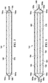
- FIG. 1 depicts an embodiment of a system 102 for treating a tissue site 104 of a patient.
- the tissue site 104 may extend through or otherwise involve an epidermis 106, a dermis 108, and a subcutaneous tissue 110.
- the tissue site 104 may be a sub-surface tissue site as depicted in FIG. 1 that extends below the surface of the epidermis 106.
- the tissue site 104 may be a surface tissue site (not shown) that predominantly resides on the surface of the epidermis 106, such as, for example, an incision.
- the system 102 may provide therapy to, for example, the epidermis 106, the dermis 108, and the subcutaneous tissue 110, regardless of the positioning of the system 102 or the type of tissue site.
- the system 102 may also be utilized without limitation at other tissue sites.
- tissue site 104 may be the bodily tissue of any human, animal, or other organism, including bone tissue, adipose tissue, muscle tissue, dermal tissue, vascular tissue, connective tissue, cartilage, tendons, ligaments, or any other tissue. Treatment of tissue site 104 may include removal of fluids, e.g., exudate or ascites.
- the system 102 may include an optional tissue interface, such as an interface manifold 120. Further, the system 102 may include a dressing 124, and a reduced-pressure source 128.
- the reduced-pressure source 128 may be a component of an optional therapy unit 130 as shown in FIG. 1 . In some embodiments, the reduced-pressure source 128 and the therapy unit 130 may be separate components.
- the interface manifold 120 is an optional component that may be omitted for different types of tissue sites or different types of therapy using reduced pressure, such as, for example, epithelialization.
- the interface manifold 120 may be adapted to be positioned proximate to or adjacent to the tissue site 104, such as, for example, by cutting or otherwise shaping the interface manifold 120 in any suitable manner to fit the tissue site 104. As described below, the interface manifold 120 may be adapted to be positioned in fluid communication with the tissue site 104 to distribute reduced pressure to the tissue site 104. In some embodiments, the interface manifold 120 may be positioned in direct contact with the tissue site 104.
- the tissue interface or the interface manifold 120 may be formed from any manifold material or flexible bolster material that provides a vacuum space, or treatment space, such as, for example, a porous and permeable foam or foam-like material, a member formed with pathways, a graft, or a gauze.
- the interface manifold 120 may be a reticulated, open-cell polyurethane or polyether foam that allows good permeability of fluids while under a reduced pressure.
- One such foam material is the VAC® GranuFoam® material available from Kinetic Concepts, Inc. (KCI) of San Antonio, Texas.
- manifold may refer to a substance or structure that is provided to assist in delivering fluids to or removing fluids from a tissue site through a plurality of pores, pathways, or flow channels.
- the plurality of pores, pathways, or flow channels may be interconnected to improve distribution of fluids provided to and removed from an area around the manifold.
- manifolds may include, without limitation, devices that have structural elements arranged to form flow channels, cellular foam, such as open-cell foam, porous tissue collections, and liquids, gels, and foams that include or cure to include flow channels.
- a material with a higher or lower density than GranuFoam® material may be desirable for the interface manifold 120 depending on the application.
- GranuFoam® material Foamex® technical foam (www.foamex.com)
- Foamex® technical foam www.foamex.com
- a patterned grid material such as those manufactured by Sercol Industrial Fabrics
- 3D textiles such as those manufactured by Baltex of Derby, U.K.
- ionic silver may be added to the interface manifold 120 by, for example, a micro bonding process.
- Other substances, such as anti-microbial agents may be added to the interface manifold 120 as well.
- the interface manifold 120 may comprise a porous, hydrophobic material.
- the hydrophobic characteristics of the interface manifold 120 may prevent the interface manifold 120 from directly absorbing fluid, such as exudate, from the tissue site 104, but allow the fluid to pass through.
- the dressing 124 may be adapted to provide reduced pressure from the reduced-pressure source 128 to the interface manifold 120, and to store fluid extracted from the tissue site 104 through the interface manifold 120.
- the dressing 124 may include a base layer 132, an adhesive 136, a sealing member 140, a fluid management assembly 144, and a conduit interface 148. Components of the dressing 124 may be added or removed to suit a particular application.
- the base layer 132 may have a periphery 152 surrounding a central portion 156, and a plurality of apertures 160 disposed through the periphery 152 and the central portion 156.
- the base layer 132 may also have corners 158 and edges 159.
- the corners 158 and the edges 159 may be part of the periphery 152.
- One of the edges 159 may meet another of the edges 159 to define one of the corners 158.
- the base layer 132 may have a border 161 substantially surrounding the central portion 156 and positioned between the central portion 156 and the periphery 152.
- the border 161 may be free of the apertures 160.
- the base layer 132 may cover the interface manifold 120 and tissue surrounding the tissue site 104 such that the central portion 156 of the base layer 132 is positioned adjacent to or proximate to the interface manifold 120, and the periphery 152 of the base layer 132 is positioned adjacent to or proximate to tissue surrounding the tissue site 104. In this manner, the periphery 152 of the base layer 132 may surround the interface manifold 120. Further, the apertures 160 in the base layer 132 may be in fluid communication with the interface manifold 120 and tissue surrounding the tissue site 104.
- the apertures 160 in the base layer 132 may have any shape, such as, for example, circles, squares, stars, ovals, polygons, slits, complex curves, rectilinear shapes, triangles, or other shapes.
- the apertures 160 may be formed by cutting, by application of local RF energy, or other suitable techniques for forming an opening.
- each of the apertures 160 of the plurality of apertures 160 may be substantially circular in shape, having a diameter and an area.
- the area of each of the apertures 160 may refer to an open space or open area defining each of the apertures 160.
- the diameter of each of the apertures 160 may define the area of each of the apertures 160.
- the area of one of the apertures 160 may be defined by multiplying the square of half the diameter of the aperture 160 by the value 3.14.
- the area of the apertures 160 described in the illustrative embodiments herein may be substantially similar to the area in other embodiments (not shown) for the apertures 160 that may have non-circular shapes.
- the diameter of each of the apertures 160 may be substantially the same, or each of the diameters may vary depending, for example, on the position of the aperture 160 in the base layer 132.
- the diameter of the apertures 160 in the periphery 152 of the base layer 132 may be larger than the diameter of the apertures 160 in the central portion 156 of the base layer 132. Further, the diameter of each of the apertures 160 may be between about 1 millimeter to about 50 millimeters. In some embodiments, the diameter of each of the apertures 160 may be between about 1 millimeter to about 20 millimeters.
- the apertures 160 may have a uniform pattern or may be randomly distributed on the base layer 132. The size and configuration of the apertures 160 may be designed to control the adherence of the dressing 124 to the epidermis 106 as described below.
- the apertures 160 positioned in the periphery 152 may be apertures 160a, the apertures 160 positioned at the corners 158 of the periphery 152 may be apertures 160b, and the apertures 160 positioned in the central portion 156 may be apertures 160c.
- the apertures 160a may have a diameter between about 9.8 millimeters to about 10.2 millimeters.
- the apertures 160b may have a diameter between about 7.75 millimeters to about 8.75 millimeters.
- the apertures 160c may have a diameter between about 1.8 millimeters to about 2.2 millimeters.
- each of the apertures 160a may be separated from one another by a distance A between about 2.8 millimeters to about 3.2 millimeters. Further, the diameter of at least one of the apertures 160a may be separated from the diameter of at least one of the apertures 160b by the distance A. The diameter of each of the apertures 160b may also be separated from one another by the distance A. A center of one of the apertures 160c may be separated from a center of another of the apertures 160c in a first direction by a distance B between about 2.8 millimeters to about 3.2 millimeters.
- the center of one of the apertures 160c may be separated from the center of another of the apertures 160c by a distance C between about 2.8 millimeters to about 3.2 millimeters.
- the distance B and the distance C may be increased for the apertures 160c in the central portion 156 being positioned proximate to or at the border 161 compared to the apertures 160c positioned away from the border 161.
- the central portion 156 of the base layer 132 may be substantially square with each side of the central portion 156 having a length D between about 100 millimeters to about 108 millimeters. In some embodiments, the length D may be between about 106 millimeters to about 108 millimeters.
- the border 161 of the base layer 132 may have a width E between about 4 millimeters to about 11 millimeters and may substantially surround the central portion 156 and the apertures 160c in the central portion 156. In some embodiments, the width E may be between about 9 millimeters to about 10 millimeters.
- the periphery 152 of the base layer 132 may have a width F between about 25 millimeters to about 35 millimeters and may substantially surround the border 161 and the central portion 156. In some embodiments, the width F may be between about 26 millimeters to about 28 millimeters. Further, the periphery 152 may have a substantially square exterior with each side of the exterior having a length G between about 154 millimeters to about 200 millimeters. In some embodiments, the length G may be between about 176 millimeters to about 184 millimeters.
- the dimensions of the base layer 132 as described herein may be increased or decreased, for example, substantially in proportion to one another to suit a particular application.
- the use of the dimensions in the proportions described above may enhance the cosmetic appearance of a tissue site.
- these proportions may provide a surface area for the base layer 132, regardless of shape, that is sufficiently smooth to enhance the movement and proliferation of epithelial cells at the tissue site 104, and reduce the likelihood of granulation tissue in-growth into the dressing 124.
- the base layer 132 may be a soft, pliable material suitable for providing a fluid seal with the tissue site 104 as described herein.
- the base layer 132 may comprise a silicone gel, a soft silicone, hydrocolloid, hydrogel, polyurethane gel, polyolefin gel, hydrogenated styrenic copolymer gels, a foamed gel, a soft closed cell foam such as polyurethanes and polyolefins coated with an adhesive described below, polyurethane, polyolefin, or hydrogenated styrenic copolymers.
- the base layer 132 may have a thickness between about 500 microns ( ⁇ m) and about 1000 microns ( ⁇ m). In some embodiments, the base layer 132 has a stiffness between about 5 Shore OO and about 80 Shore OO.
- the base layer 132 may be comprised of hydrophobic or hydrophilic materials.
- the base layer 132 may be a hydrophobic-coated material.
- the base layer 132 may be formed by coating a spaced material, such as, for example, woven, nonwoven, molded, or extruded mesh with a hydrophobic material.
- the hydrophobic material for the coating may be a soft silicone, for example.
- the adhesive 136 may extend through openings in the spaced material analogous to the apertures 160 described below.
- the adhesive 136 may be in fluid communication with the apertures 160 in at least the periphery 152 of the base layer 132. In this manner, the adhesive 136 may be in fluid communication with the tissue surrounding the tissue site 104 through the apertures 160 in the base layer 132. As described below and shown in FIG. 3 , the adhesive 136 may extend or be pressed through the plurality of apertures 160 to contact the epidermis 106 for securing the dressing 124 to, for example, the tissue surrounding the tissue site 104. The apertures 160 may provide sufficient contact of the adhesive 136 to the epidermis 106 to secure the dressing 124 about the tissue site 104. However, the configuration of the apertures 160 and the adhesive 136, described below, may permit release and repositioning of the dressing 124 about the tissue site 104.
- At least one of the apertures 160a in the periphery 152 of the base layer 132 may be positioned at the edges 159 of the periphery 152 and may have an interior cut open or exposed at the edges 159 that is in fluid communication in a lateral direction with the edges 159.
- the lateral direction may refer to a direction toward the edges 159 and in the same plane as the base layer 132.
- a plurality of the apertures 160a in the periphery 152 may be positioned proximate to or at the edges 159 and in fluid communication in a lateral direction with the edges 159.
- the apertures 160a positioned proximate to or at the edges 159 may be spaced substantially equidistant around the periphery 152 as shown in FIGS. 4A-4B . However, in some embodiments, the spacing of the apertures 160a proximate to or at the edges 159 may be irregular.
- the adhesive 136 may be in fluid communication with the edges 159 through the apertures 160a being exposed at the edges 159. In this manner, the apertures 160a at the edges 159 may permit the adhesive 136 to flow around the edges 159 for enhancing the adhesion of the edges 159 around the tissue site 104, for example.
- the apertures 160b at the corners 158 of the periphery 152 may be smaller than the apertures 160a in other portions of the periphery 152 as described above.
- the smaller size of the apertures 160b compared to the apertures 160a may maximize the surface area of the adhesive 136 exposed and in fluid communication through the apertures 160b at the corners 158.
- the edges 159 may intersect at substantially a right angle, or about 90 degrees, to define the corners 158.
- the corners 158 may have a radius of about 10 millimeters.
- Three of the apertures 160b having a diameter between about 7.75 millimeters to about 8.75 millimeters may be positioned in a triangular configuration at the corners 158 to maximize the exposed surface area for the adhesive 136.
- the size and number of the apertures 160b in the corners 158 may be adjusted as necessary, depending on the chosen geometry of the corners 158, to maximize the exposed surface area of the adhesive 136 as described above.
- the apertures 160b at the corners 158 may be fully housed within the base layer 132, substantially precluding fluid communication in a lateral direction exterior to the corners 158.
- the apertures 160b at the corners 158 being fully housed within the base layer 132 may substantially preclude fluid communication of the adhesive 136 exterior to the corners 159, and may provide improved handling of the dressing 124 during deployment at the tissue site 104. Further, the exterior of the corners 158 being substantially free of the adhesive 136 may increase the flexibility of the corners 158 to enhance comfort.
- any of the apertures 160 may be adjusted in size and number to maximize the surface area of the adhesive 136 in fluid communication through the apertures 160 for a particular application or geometry of the base layer 132.
- the apertures 160b, or apertures of another size may be positioned in the periphery 152 and at the border 161.
- the apertures 160b, or apertures of another size may be positioned as described above in other locations of the base layer 132 that may have a complex geometry or shape.
- the adhesive 136 may be a medically-acceptable adhesive.
- the adhesive 136 may also be flowable.
- the adhesive 136 may comprise an acrylic adhesive, rubber adhesive, high-tack silicone adhesive, polyurethane, or other adhesive substance.
- the adhesive 136 may be a pressure-sensitive adhesive comprising an acrylic adhesive with coating weight of 15 grams/m 2 (gsm) to 70 grams/m 2 (gsm).
- the adhesive 136 may be a layer having substantially the same shape as the periphery 152 of the base layer 132 as shown in FIG. 4A .
- the layer of the adhesive 136 may be continuous or discontinuous. Discontinuities in the adhesive 136 may be provided by apertures (not shown) in the adhesive 136.
- the apertures in the adhesive 136 may be formed after application of the adhesive 136 or by coating the adhesive 136 in patterns on a carrier layer, such as, for example, a side of the sealing member 140 adapted to face the epidermis 106. Further, the apertures in the adhesive 136 may be sized to control the amount of the adhesive 136 extending through the apertures 160 in the base layer 132 to reach the epidermis 106. The apertures in the adhesive 136 may also be sized to enhance the Moisture Vapor Transfer Rate (MVTR) of the dressing 124, described further below.
- MVTR Moisture Vapor Transfer Rate
- Factors that may be utilized to control the adhesion strength of the dressing 124 may include the diameter and number of the apertures 160 in the base layer 132, the thickness of the base layer 132, the thickness and amount of the adhesive 136, and the tackiness of the adhesive 136.
- An increase in the amount of the adhesive 136 extending through the apertures 160 generally corresponds to an increase in the adhesion strength of the dressing 124.
- a decrease in the thickness of the base layer 132 generally corresponds to an increase in the amount of adhesive 136 extending through the apertures 160.
- the diameter and configuration of the apertures 160, the thickness of the base layer 132, and the amount and tackiness of the adhesive utilized may be varied to provide a desired adhesion strength for the dressing 124.
- the thickness of the base layer 132 may be about 200 microns
- the adhesive layer 136 may have a thickness of about 30 microns and a tackiness of 2000 grams per 25 centimeter wide strip
- the diameter of the apertures 160a in the base layer 132 may be about 10 millimeters.
- the tackiness of the adhesive 136 may vary in different locations of the base layer 132.
- the adhesive 136 may have a lower tackiness than other locations of the base layer 132 where the apertures 160 are smaller, such as the apertures 160b and 160c.
- locations of the base layer 132 having larger apertures 160 and lower tackiness adhesive 136 may have an adhesion strength comparable to locations having smaller apertures 160 and higher tackiness adhesive 136.
- a release liner 162 may be attached to or positioned adjacent to the base layer 132 to protect the adhesive 136 prior to application of the dressing 124 to the tissue site 104.
- the base layer 132 Prior to application of the dressing 124 to the tissue site 104, the base layer 132 may be positioned between the sealing member 140 and the release liner 162. Removal of the release liner 162 may expose the base layer 132 and the adhesive 136 for application of the dressing 124 to the tissue site 104.
- the release liner 162 may also provide stiffness to assist with, for example, deployment of the dressing 124.
- the release liner 162 may be, for example, a casting paper, a film, or polyethylene.
- the release liner 162 may be a polyester material such as polyethylene terephthalate (PET), or similar polar semi-crystalline polymer.
- PET polyethylene terephthalate
- the use of a polar semi-crystalline polymer for the release liner 162 may substantially preclude wrinkling or other deformation of the dressing 124.
- the polar semi-crystalline polymer may be highly orientated and resistant to softening, swelling, or other deformation that may occur when brought into contact with components of the dressing 124, or when subjected to temperature or environmental variations, or sterilization.
- a release agent may be disposed on a side of the release liner 162 that is configured to contact the base layer 132.
- the release agent may be a silicone coating and may have a release factor suitable to facilitate removal of the release liner 162 by hand and without damaging or deforming the dressing 124.
- the release agent may be flourosilicone.
- the release liner 162 may be uncoated or otherwise used without a release agent.
- the sealing member 140 has a periphery 164 and a central portion 168.
- the sealing member 140 may additionally include an aperture 170, as described below.
- the periphery 164 of the sealing member 140 may be positioned proximate to the periphery 152 of the base layer 132 such that the central portion 168 of the sealing member 140 and the central portion 156 of the base layer 132 define an enclosure 172.
- the adhesive 136 may be positioned at least between the periphery 164 of the sealing member 140 and the periphery 152 of the base layer 132.
- the sealing member 140 may cover the tissue site 104 and the interface manifold 120 to provide a fluid seal and a sealed space 174 between the tissue site 104 and the sealing member 140 of the dressing 124. Further, the sealing member 140 may cover other tissue, such as a portion of the epidermis 106, surrounding the tissue site 104 to provide the fluid seal between the sealing member 140 and the tissue site 104. In some embodiments, a portion of the periphery 164 of the sealing member 140 may extend beyond the periphery 152 of the base layer 132 and into direct contact with tissue surrounding the tissue site 104.
- the periphery 164 of the sealing member 140 may be positioned in contact with tissue surrounding the tissue site 104 to provide the sealed space 174 without the base layer 132.
- the adhesive 136 may also be positioned at least between the periphery 164 of the sealing member 140 and tissue, such as the epidermis 106, surrounding the tissue site 104.
- the adhesive 136 may be disposed on a surface of the sealing member 140 adapted to face the tissue site 104 and the base layer 132.
- the sealing member 140 may be formed from any material that allows for a fluid seal.
- a fluid seal is a seal adequate to maintain reduced pressure at a desired site given the particular reduced pressure source or system involved.
- the sealing member 140 may comprise, for example, one or more of the following materials: hydrophilic polyurethane; cellulosics; hydrophilic polyamides; polyvinyl alcohol; polyvinyl pyrrolidone; hydrophilic acrylics; hydrophilic silicone elastomers; an INSPIRE 2301 material from Expopack Advanced Coatings of Wrexham, United Kingdom having, for example, an MVTR (inverted cup technique) of 14400 g/m 2 /24 hours and a thickness of about 30 microns; a thin, uncoated polymer drape; natural rubbers; polyisoprene; styrene butadiene rubber; chloroprene rubber; polybutadiene; nitrile rubber; butyl rubber; ethylene propylene rubber; ethylene propylene dien
- the sealing member 140 may be vapor permeable and liquid impermeable, thereby allowing vapor and inhibiting liquids from exiting the sealed space 174 provided by the dressing 124.
- the sealing member 140 may be a flexible, breathable film, membrane, or sheet having a high MVTR of, for example, at least about 300g/m 2 per 24 hours. In other embodiments, a low or no vapor transfer drape might be used.
- the sealing member 140 may comprise a range of medically suitable films having a thickness between about 15 microns ( ⁇ m) to about 50 microns ( ⁇ m).
- the fluid management assembly 144 may be disposed in the enclosure 172 and may include a first wicking layer 176, a second wicking layer 180, and an absorbent layer 184.
- the absorbent layer 184 may be positioned in fluid communication between the first wicking layer 176 and the second wicking layer 180.
- the first wicking layer 176 may have a grain structure (not shown) adapted to wick fluid along a surface of the first wicking layer 176.
- the second wicking layer 180 may have a grain structure (not shown) adapted to wick fluid along a surface of the second wicking layer 180.
- first wicking layer 176 and the second wicking layer 180 may wick or otherwise transport fluid in a lateral direction along the surfaces of the first wicking layer 176 and the second wicking layer 180, respectively.
- the surfaces of the first wicking layer 176 and the second wicking layer 180 may be normal relative to the thickness of each of the first wicking layer 176 and the second wicking layer 180.
- the wicking of fluid along the first wicking layer 176 and the second wicking layer 180 may enhance the distribution of the fluid over a surface area of the absorbent layer 184 that may increase absorbent efficiency and resist fluid blockages.
- Fluid blockages may be caused by, for example, fluid pooling in a particular location in the absorbent layer 184 rather than being distributed more uniformly across the absorbent layer 184.
- the laminate combination of the first wicking layer 176, the second wicking layer 180, and the absorbent layer 184 may be adapted as described above to maintain an open structure, resistant to blockage, capable of maintaining fluid communication with, for example, the tissue site 104.
- a peripheral portion 186 of the first wicking layer 176 may be coupled to a peripheral portion 187 of the second wicking layer 180 to define a wicking layer enclosure 188 between the first wicking layer 176 and the second wicking layer 180.
- the wicking layer enclosure 188 may surround or otherwise encapsulate the absorbent layer 184 between the first wicking layer 176 and the second wicking layer 180.
- the fluid management assembly 144 may include, without limitation, any number of wicking layers and absorbent layers as desired for treating a particular tissue site.
- the absorbent layer 184 may be a plurality of absorbent layers 184 positioned in fluid communication between the first wicking layer 176 and the second wicking layer 180 as described above.
- at least one intermediate wicking layer 189 may be disposed in fluid communication between the plurality of absorbent layers 184.
- the plurality of absorbent layers 184 and the at least one intermediate wicking layer 189 may be positioned within the wicking layer enclosure 188.
- the absorbent layer 184 may be disposed between the sealing member 140 and the interface manifold 120, and the first wicking layer 176 and the second wicking layer 180 may be omitted.
- sides 184a of the absorbent layers 184 may remain in fluid communication with one another for enhancing efficiency.
- sides 189a of the at least one intermediate wicking layer 189 may remain in fluid communication with one another and with the sides 184a of the absorbent layers 184.
- additional absorbent layers 184 may increase the absorbent mass of the fluid management assembly 144 and generally provide greater fluid capacity.
- multiple light coat-weight absorbent layers 184 may be utilized rather than a single heavy coat-weight absorbent layer 184 to provide a greater absorbent surface area for further enhancing the absorbent efficiency.
- the absorbent layer 184 may be a hydrophilic material adapted to absorb fluid from, for example, the tissue site 104.
- Materials suitable for the absorbent layer 184 may include Luquafleece® material, Texsus FP2326, BASF 402C, Technical Absorbents 2317 available from Technical Absorbents (www.techabsorbents.com), sodium polyacrylate super absorbers, cellulosics (carboxy methyl cellulose and salts such as sodium CMC), or alginates.
- Materials suitable for the first wicking layer 176 and the second wicking layer 180 may include any material having a grain structure capable of wicking fluid as described herein, such as, for example, Libeltex TDL2 80gsm.
- the fluid management assembly 144 may be a pre-laminated structure manufactured at a single location or individual layers of material stacked upon one another as described above. Individual layers of the fluid management assembly 144 may be bonded or otherwise secured to one another without adversely affecting fluid management by, for example, utilizing a solvent or non-solvent adhesive, or by thermal welding. Further, the fluid management assembly 144 may be coupled to the border 161 of the base layer 132 in any suitable manner, such as, for example, by a weld or an adhesive. The border 161 being free of the apertures 160 as described above may provide a flexible barrier between the fluid management assembly 144 and the tissue site 104 for enhancing comfort.
- the enclosure 172 defined by the base layer 132 and the sealing member 140 may include an anti-microbial layer 190.
- the addition of the anti-microbial layer 190 may reduce the probability of excessive bacterial growth within the dressing 124 to permit the dressing 124 to remain in place for an extended period.
- the anti-microbial layer 190 may be, for example, an additional layer included as a part of the fluid management assembly 144 as depicted in FIGS. 1 and 2 , or a coating of an anti-microbial agent disposed in any suitable location within the dressing 124.
- the anti-microbial layer 190 may be comprised of elemental silver or similar compound, for example.
- the anti-microbial agent may be formulated in any suitable manner into other components of the dressing 124.
- the conduit interface 148 may be positioned proximate to the sealing member 140 and in fluid communication with the dressing 124 through the aperture 170 in the sealing member 140 to provide reduced pressure from the reduced-pressure source 128 to the dressing 124.
- the conduit interface 148 may be positioned in fluid communication with the enclosure 172 of the dressing 124.
- the conduit interface 148 may also be positioned in fluid communication with the optional interface manifold 120.
- an optional liquid trap 192 may be positioned in fluid communication between the dressing 124 and the reduced-pressure source 128.
- the liquid trap 192 may be any suitable containment device having a sealed internal volume capable of retaining liquid, such as condensate or other liquids, as described below.
- the conduit interface 148 may comprise a medical-grade, soft polymer or other pliable material.
- the conduit interface 148 may be formed from polyurethane, polyethylene, polyvinyl chloride (PVC), fluorosilicone, or ethylenepropylene, etc.
- conduit interface 148 may be molded from DEHP-free PVC.
- the conduit interface 148 may be formed in any suitable manner such as by molding, casting, machining, or extruding. Further, the conduit interface 148 may be formed as an integral unit or as individual components and may be coupled to the dressing 124 by, for example, adhesive or welding.
- the conduit interface 148 may be formed of an absorbent material having absorbent and evaporative properties.
- the absorbent material may be vapor permeable and liquid impermeable, thereby being configured to permit vapor to be absorbed into and evaporated from the material through permeation while inhibiting permeation of liquids.
- the absorbent material may be, for example, a hydrophilic polymer such as a hydrophilic polyurethane. Although the term hydrophilic polymer may be used in the illustrative embodiments that follow, any absorbent material having the properties described herein may be suitable for use in the system 102. Further, the absorbent material or hydrophilic polymer may be suitable for use in various components of the system 102 as described herein.
- hydrophilic polymer for the conduit interface 148 may permit liquids in the conduit interface 148 to evaporate, or otherwise dissipate, during operation.
- the hydrophilic polymer may allow the liquid to permeate or pass through the conduit interface 148 as vapor, in a gaseous phase, and evaporate into the atmosphere external to the conduit interface 148.
- Such liquids may be, for example, condensate or other liquids. Condensate may form, for example, as a result of a decrease in temperature within the conduit interface 148, or other components of the system 102, relative to the temperature at the tissue site 104. Removal or dissipation of liquids from the conduit interface 148 may increase visual appeal and prevent odor. Further, such removal of liquids may also increase efficiency and reliability by reducing blockages and other interference with the components of the system 102.
- the liquid trap 192, and other components of the system 102 described herein may also be formed of an absorbent material or a hydrophilic polymer.
- the absorptive and evaporative properties of the hydrophilic polymer may also facilitate removal and dissipation of liquids residing in the liquid trap 192, and other components of the system 102, by evaporation. Such evaporation may leave behind a substantially solid or gel-like waste.
- the substantially solid or gel-like waste may be cheaper to dispose than liquids, providing a cost savings for operation of the system 102.
- the hydrophilic polymer may be used for other components in the system 102 where the management of liquids is beneficial.
- the absorbent material or hydrophilic polymer may have an absorbent capacity in a saturated state that is substantially equivalent to the mass of the hydrophilic polymer in an unsaturated state.
- the hydrophilic polymer may be fully saturated with vapor in the saturated state and substantially free of vapor in the unsaturated state. In both the saturated state and the unsaturated state, the hydrophilic polymer may retain substantially the same physical, mechanical, and structural properties.
- the hydrophilic polymer may have a hardness in the unsaturated state that is substantially the same as a hardness of the hydrophilic polymer in the saturated state.
- the hydrophilic polymer and the components of the system 102 incorporating the hydrophilic polymer may also have a size that is substantially the same in both the unsaturated state and the saturated state. Further, the hydrophilic polymer may remain dry, cool to the touch, and pneumatically sealed in the saturated state and the unsaturated state. The hydrophilic polymer may also remain substantially the same color in the saturated state and the unsaturated state. In this manner, this hydrophilic polymer may retain sufficient strength and other physical properties to remain suitable for use in the system 102.
- An example of such a hydrophilic polymer is offered under the trade name Techophilic HP-93A-100, available from The Lubrizol Corporation of Wickliffe, Ohio, United States. Techophilic HP-93A-100 is an absorbent hydrophilic thermoplastic polyurethane capable of absorbing 100% of the unsaturated mass of the polyurethane in water and having a durometer or Shore Hardness of about 83 Shore A.
- the conduit interface 148 may carry an odor filter 194 adapted to substantially preclude the passage of odors from the tissue site 104 out of the sealed space 174. Further, the conduit interface 148 may carry a primary hydrophobic filter 195 adapted to substantially preclude the passage of liquids out of the sealed space 174.
- the odor filter 194 and the primary hydrophobic filter 195 may be disposed in the conduit interface 148 or other suitable location such that fluid communication between the reduced-pressure source 128, or optional therapy unit 130, and the dressing 124 is provided through the odor filter 194 and the primary hydrophobic filter 195.
- the odor filter 194 and the primary hydrophobic filter 195 may be secured within the conduit interface 148 in any suitable manner, such as by adhesive or welding.
- the odor filter 194 and the primary hydrophobic filter 195 may be positioned in any exit location in the dressing 124 that is in fluid communication with the atmosphere, the reduced-pressure source 128, or the optional therapy unit 130.
- the odor filter 194 may also be positioned in any suitable location in the system 102 that is in fluid communication with the tissue site 104.
- the odor filter 194 may be comprised of a carbon material in the form of a layer or particulate.
- the odor filter 194 may comprise a woven carbon cloth filter such as those manufactured by Chemviron Carbon, Ltd. of Lancashire, United Kingdom (www.chemvironcarbon.com).
- the primary hydrophobic filter 195 may be comprised of a material that is liquid impermeable and vapor permeable.
- the primary hydrophobic filter 195 may comprise a material manufactured under the designation MMT-314 by W.L. Gore & Associates, Inc. of Newark, Delaware, United States, or similar materials.
- the primary hydrophobic filter 195 may be provided in the form of a membrane or layer.
- the reduced-pressure source 128 provides reduced pressure to the dressing 124 and the sealed space 174.
- the reduced-pressure source 128 may be any suitable device for providing reduced pressure, such as, for example, a vacuum pump, wall suction, hand pump, or other source.
- the reduced-pressure source 128 may be a component of the therapy unit 130.
- the therapy unit 130 may include control circuitry and sensors, such as a pressure sensor, that may be configured to monitor reduced pressure at the tissue site 104.
- the therapy unit 130 may also be configured to control the amount of reduced pressure from the reduced-pressure source 128 being applied to the tissue site 104 according to a user input and a reduced-pressure feedback signal received from the tissue site 104.
- reduced pressure generally refers to a pressure less than the ambient pressure at a tissue site being subjected to treatment. Typically, this reduced pressure will be less than the atmospheric pressure. The reduced pressure may also be less than a hydrostatic pressure at a tissue site. Unless otherwise indicated, values of pressure stated herein are gauge pressures. While the amount and nature of reduced pressure applied to a tissue site will typically vary according to the application, the reduced pressure will typically be between -5 mm Hg and -500 mm Hg, and more typically in a therapeutic range between -100 mm Hg and -200 mm Hg.
- the reduced pressure delivered may be constant or varied (patterned or random), and may be delivered continuously or intermittently.
- vacuum and “negative pressure” may be used to describe the pressure applied to the tissue site, the actual pressure applied to the tissue site may be more than the pressure normally associated with a complete vacuum.
- an increase in reduced pressure or vacuum pressure typically refers to a relative reduction in absolute pressure.
- An increase in reduced pressure corresponds to a reduction in pressure (more negative relative to ambient pressure) and a decrease in reduced pressure corresponds to an increase in pressure (less negative relative to ambient pressure).
- a conduit 196 having an internal lumen 197 may be coupled in fluid communication between the reduced-pressure source 128 and the dressing 124.
- the internal lumen 197 may have an internal diameter between about 0.5 millimeters to about 3.0 millimeters. More specifically, the internal diameter of the internal lumen 197 may be between about 1 millimeter to about 2 millimeters.
- the conduit interface 148 may be coupled in fluid communication with the dressing 124 and adapted to connect between the conduit 196 and the dressing 124 for providing fluid communication with the reduced-pressure source 128.
- the conduit interface 148 may be fluidly coupled to the conduit 196 in any suitable manner, such as, for example, by an adhesive, solvent or non-solvent bonding, welding, or interference fit.
- the aperture 170 in the sealing member 140 may provide fluid communication between the dressing 124 and the conduit interface 148.
- the conduit interface 148 may be in fluid communication with the enclosure 172 or the sealed space 174 through the aperture 170 in the sealing member 140.
- the conduit 196 may be inserted into the dressing 124 through the aperture 170 in the sealing member 140 to provide fluid communication with the reduced-pressure source 128 without use of the conduit interface 148.
- the reduced-pressure source 128 may also be directly coupled in fluid communication with the dressing 124 or the sealing member 140 without use of the conduit 196.
- the conduit 196 may be, for example, a flexible polymer tube.
- a distal end of the conduit 196 may include a coupling 198 for attachment to the reduced-pressure source 128.
- the conduit 196 may have a secondary hydrophobic filter 199 disposed in the internal lumen 197 such that fluid communication between the reduced-pressure source 128 and the dressing 124 is provided through the secondary hydrophobic filter 199.
- the secondary hydrophobic filter 199 may be, for example, a porous, sintered polymer cylinder sized to fit the dimensions of the internal lumen 197 to substantially preclude liquid from bypassing the cylinder.
- the secondary hydrophobic filter 199 may also be treated with an absorbent material adapted to swell when brought into contact with liquid to block the flow of the liquid.
- the secondary hydrophobic filter 199 may be positioned at any location within the internal lumen 197. However, positioning the secondary hydrophobic filter 199 within the internal lumen 197 closer toward the reduced-pressure source 128, rather than the dressing 124, may allow a user to detect the presence of liquid in the internal lumen 197.
- the conduit 196 and the coupling 198 may be formed of an absorbent material or a hydrophilic polymer as described above for the conduit interface 148. In this manner, the conduit 196 and the coupling 198 may permit liquids in the conduit 196 and the coupling 198 to evaporate, or otherwise dissipate, as described above for the conduit interface 148.
- the conduit 196 and the coupling 198 may be, for example, molded from the hydrophilic polymer separately, as individual components, or together as an integral component. Further, a wall of the conduit 196 defining the internal lumen 197 may be extruded from the hydrophilic polymer.
- the conduit 196 may be less than about 1 meter in length, but may have any length to suit a particular application.
- a length of about 1 foot or 304.8 millimeters may provide enough absorbent and evaporative surface area to suit many applications, and may provide a cost savings compared to longer lengths. If an application requires additional length for the conduit 196, the absorbent hydrophilic polymer may be coupled in fluid communication with a length of conduit formed of a non-absorbent hydrophobic polymer to provide additional cost savings.
- FIG. 8 depicts the dressing 124 including a fluid management assembly 244 suitable for use with the dressing 124 and the system 102.
- the fluid management assembly 244 may include a first wicking layer 276, a second wicking layer 280, and an absorbent layer 284 comprised of substantially the same materials and properties as those described above in connection with the fluid management assembly 144.
- the first wicking layer 276, the second wicking layer 280, and the absorbent layer 284 are analogous to the first wicking layer 176, the second wicking layer 180, and the absorbent layer 184, respectively.
- the second wicking layer 280 may have a peripheral portion 287.
- the second wicking layer 280 and the peripheral portion 287 of the second wicking layer 280 may be positioned in contact with the sealing member 140.
- the absorbent layer 284 may have a peripheral portion 285 extending beyond the peripheral portion 287 of the second wicking layer 280.
- the absorbent layer 284 may be positioned adjacent to or proximate to the second wicking layer 280 such that the peripheral portion 285 of the absorbent layer 284 is in contact with the sealing member 140 surrounding the peripheral portion 287 of the second wicking layer 280.
- the first wicking layer 276 may have a peripheral portion 286 extending beyond the peripheral portion 285 of the absorbent layer 284.
- the first wicking layer 276 may be positioned adjacent to or proximate to the absorbent layer 284 such that the peripheral portion 286 of the first wicking layer 276 is in contact with the sealing member 140 surrounding the peripheral portion 285 of the absorbent layer 284. Further, the first wicking layer 276 may be positioned adjacent to or proximate to the base layer 132. Thus, at least the peripheral portion 287, the peripheral portion 285, and the peripheral portion 286 in contact with the sealing member 140 may be coupled to the sealing member 140, such as, for example, by an adhesive coating disposed on a surface of the sealing member 140 facing the base layer 132. The adhesive coating may be analogous to the adhesive 136 being applied across the surface of the sealing member 140 facing the base layer 132.
- the second wicking layer 280, the absorbent layer 284, and the first wicking layer 276 may respectively have increasing surface areas to enhance contact with the adhesive coating described above.
- the fluid management assembly 244 may include any number of absorbent layers and wicking layers for treating a particular tissue site.
- the interface manifold 120 may be disposed against or proximate to the tissue site 104.
- the dressing 124 may then be applied over the interface manifold 120 and the tissue site 104 to form the sealed space 174.
- the base layer 132 may be applied covering the interface manifold 120 and the tissue surrounding the tissue site 104.
- the materials described above for the base layer 132 have a tackiness that may hold the dressing 124 initially in position. The tackiness may be such that if an adjustment is desired, the dressing 124 may be removed and reapplied.
- a force may be applied, such as by hand pressing, on a side of the sealing member 140 opposite the tissue site 104.
- the force applied to the sealing member 140 may cause at least some portion of the adhesive 136 to penetrate or extend through the plurality of apertures 160 and into contact with tissue surrounding the tissue site 104, such as the epidermis 106, to releaseably adhere the dressing 124 about the tissue site 104.
- the configuration of the dressing 124 described above may provide an effective and reliable seal against challenging anatomical surfaces, such as an elbow or heal, at and around the tissue site 104.
- the dressing 124 permits re-application or re-positioning to, for example, correct air leaks caused by creases and other discontinuities in the dressing 124 and the tissue site 104.
- the ability to rectify leaks may increase the reliability of the therapy and reduce power consumption.
- the fluid management assembly 144, 244 wicks or otherwise moves the fluid through the interface manifold 120 and away from the tissue site 104.
- the interface manifold 120 may be adapted to communicate fluid from the tissue site 104 rather than store the fluid.
- the fluid management assembly 144, 244 may be more absorbent than the interface manifold 120.
- the fluid management assembly 144, 244 being more absorbent than the interface manifold 120 provides an absorbent gradient through the dressing 124 that attracts fluid from the tissue site 104 or the interface manifold 120 to the fluid management assembly 144, 244.
- the fluid management assembly 144, 244 may be adapted to wick, pull, draw, or otherwise attract fluid from the tissue site 104 through the interface manifold 120.
- the fluid initially comes into contact with the first wicking layer 176, 276.
- the first wicking layer 176, 276 may distribute the fluid laterally along the surface of the first wicking layer 176, 276 as described above for absorption and storage within the absorbent layer 184, 284.
- fluid coming into contact with the second wicking layer 180, 280 may be distributed laterally along the surface of the second wicking layer 180, 280 for absorption within the absorbent layer 184, 284.
- the conduit 196 is a multi-lumen conduit 302.
- FIG. 9A depicts an illustrative example of a multi-lumen conduit 302a.
- the multi-lumen conduit 302a may have an external surface 306, a primary lumen 310, a wall 314, and at least one secondary lumen 318.
- the wall 314 may carry the primary lumen 310 and the at least one secondary lumen 318.
- the primary lumen 310 may be substantially isolated from fluid communication with the at least one secondary lumen 318 along the length of the multi-lumen conduit 302a.
- the external surface 306 of the multi-lumen conduit 302a may have any shape to suit a particular application.
- the wall 314 of the multi-lumen conduit 302a may have a thickness between the primary lumen 310 and the external surface 306.
- the at least one secondary lumen 318 may be four secondary lumens 318 carried by the wall 314 substantially parallel to the primary lumen 310 and about a perimeter of the primary lumen 310.
- the secondary lumens 318 may be separate from one another and substantially isolated from fluid communication with one another along the length of the multi-lumen conduit 302a.
- the secondary lumens 318 may be separate from the primary lumen 310 and substantially isolated from fluid communication with the primary lumen 310.
- the secondary lumens 318 may also be positioned concentric relative to the primary lumen 310 and substantially equidistant about the perimeter of the primary lumen 310.
- FIG. 9A depicts four secondary lumens 318, any number of secondary lumens 318 may be provided and positioned in any suitable manner for a particular application.
- the primary lumen 310 may be coupled in fluid communication between the reduced-pressure source 128 and the dressing 124 as described above. In some embodiments, the primary lumen 310 may be coupled in fluid communication between the conduit interface 148 and the reduced-pressure source 128. Further, analogous to the internal lumen 197, reduced pressure may be provided through the primary lumen 310 from the reduced-pressure source 128 to the dressing 124. In some embodiments, the primary lumen 310 may be configured to extract fluid such as exudate from the tissue site 104. The secondary lumens 318 may be coupled in fluid communication between the therapy unit 130 and the dressing 124.
- the at least one secondary lumen 318 may be coupled in fluid communication between the conduit interface 148 and the therapy unit 130. Further, the secondary lumens 318 may be in fluid communication with the primary lumen 310 at the dressing 124 and configured to provide a reduced-pressure feedback signal from the dressing 124 to the therapy unit 130. For example, the secondary lumens 318 may be in fluid communication with the primary lumen 310 at the conduit interface 148 or other component of the dressing 124.
- the multi-lumen conduit 302a may be comprised of an absorbent material or hydrophilic polymer, such as, for example, the absorbent material or the hydrophilic polymer described above in connection with the conduit interface 148, the conduit 196, and the coupling 198.
- the absorbent material or the hydrophilic polymer may be vapor permeable and liquid impermeable.
- at least a portion of the wall 314 and the external surface 306 of the multi-lumen conduit 302a may be comprised of the absorbent material or the hydrophilic polymer. In this manner, the multi-lumen conduit 302a may permit liquids, such as condensate, in the multi-lumen conduit 302a to evaporate, or otherwise dissipate, as described above.
- the absorbent material or the hydrophilic polymer may allow the liquid to pass through the multi-lumen conduit 302a as vapor, in a gaseous phase, and evaporate into the atmosphere external to the multi-lumen conduit 302a.
- Liquids such as exudate from the tissue site 104 may also be evaporated or dissipated through the multi-lumen conduit 302a in the same manner.
- This feature may be advantageous when the optional therapy unit 130 is used for monitoring and controlling reduced pressure at the tissue site 104.
- liquid present in the secondary lumens 318 may interfere with a reduced-pressure feedback signal being transmitted to the therapy unit 130 through the secondary lumens 318.
- the use of the hydrophilic polymer for the multi-lumen conduit 302a may permit removal of such liquid for enhancing the visual appeal, reliability, and efficiency of the system 102. After evaporation of liquid in the multi-lumen conduit 302a, other blockages from, for example, desiccated exudate, solids, or gel-like substances that were carried by the evaporated liquid may be visible for further remediation. Further, the use of the hydrophilic polymer as described herein may reduce the occurrence of skin damage caused by moisture buildup between components of the system 102, such as the multi-lumen conduit 302a, and the skin of a patient.
- FIG. 9B Depicted in FIG. 9B is an illustrative embodiment of a multi-lumen conduit 302b. Similar to the multi-lumen conduit 302a, the multi-lumen conduit 302b may have the external surface 306, the primary lumen 310, the wall 314, and the at least one secondary lumen 318 as described above.
- the wall 314 of the multi-lumen conduit 302b may include a first wall material 314a and a second wall material 314b.
- the first wall material 314a and the second wall material 314b may be comprised of different materials to form the wall 314.
- the first wall material 314a may comprise a substantially non-absorbent hydrophobic polymer, or other material, that is vapor impermeable and liquid impermeable.
- the first wall material 314a may completely surround the primary lumen 310, defining the primary lumen 310 as shown in FIG. 9B . In some embodiments (not shown), the first wall material 314a may be positioned around the primary lumen 310 without completely surrounding or defining the primary lumen 310.
- the second wall material 314b may comprise the same absorbent material or hydrophilic polymer described above for the multi-lumen conduit 302a as being vapor permeable and liquid impermeable. As shown in FIG. 9B , the second wall material 314b may be positioned in fluid contact with the at least one secondary lumen 318.
- the second wall material 314b may also define the at least one secondary lumen 318 and at least a portion of the external surface 306 of the multi-lumen conduit 302b. In some embodiments (not shown), the second wall material 314b may substantially surround the at least one secondary lumen 318 without completely defining the secondary lumen 318.
- the first wall material 314a may be substantially concentric about the primary lumen 310
- the second wall material 314b may be substantially concentric about and contiguous with the first wall material 314a.
- the first wall material 314a and the second wall material 314b may be molded, co-extruded, or otherwise combined with one another in any suitable manner to form the wall 314.
- the wall 314, including the first wall material 314a and the second wall material 314b, may provide a cost savings while retaining the absorbent and evaporative properties of the hydrophilic polymer for remediating liquid in the multi-lumen conduit 302b and the at least one secondary lumen 318.
- first wall material 314a as described herein may provide sufficient strength and other physical properties for the multi-lumen conduit 302b to remain serviceable under reduced pressure in the system 102 without regard to the physical properties of second wall material 314b.
- the use of a non-absorbent hydrophobic polymer for the first wall material 314a may permit the use of absorbent hydrophilic polymers for the second wall material 314b that may not otherwise have sufficient strength for use under reduced pressure in the system 102.
- the first wall material 314a may be combined with the second wall material 314b to form the wall 314 in various configurations for remediating liquid in the multi-lumen conduit 302 and the at least one secondary lumen 318.
- FIG. 9C depicted is an illustrative embodiment of a multi-lumen conduit 302c. Similar to the multi-lumen conduits 302a and 302b, the multi-lumen conduit 302c may have the external surface 306, the primary lumen 310, the wall 314, and the at least one secondary lumen 318. As shown in FIG.
- the wall 314 of the multi-lumen conduit 302c may include the first wall material 314a positioned around the primary lumen 310 and the second wall material 314b disposed in separate portions around each of the secondary lumens 318.
- the external surface 306 may comprise both the first wall material 314a and the second wall material 314b.
- the first wall material 314a may completely surround the primary lumen 310.
- the second wall material 314b may be disposed as portions separate from one another and separate from the primary lumen in a radial configuration about the perimeter of the primary lumen 310.
- the second wall material 314b may be in fluid contact with the primary lumen 310 and may form a portion of the external surface 306.
- the amount of the second wall material 314b surrounding the secondary lumens 318 may be increased or decreased to suit a particular application depending, for example, on the amount of liquid anticipated to be present and the desired mechanical properties of the multi-lumen conduit 302c.
- the first wall material 314a may have a receptor 320 configured to receive the second wall material 314b.
- the second wall material 314b surrounding the secondary lumens 318 may have a shape corresponding to the receptor 320 in the first wall material 314a.
- each portion of the second wall material 314b may have a taper 321a configured to engage a corresponding taper 321b of the receptor 320.
- the taper 321b may be oriented opposite the taper 321a.
- the taper 321b of the receptor 320 may taper from the external surface 306 to a smaller dimension toward the primary lumen 310.
- the taper 321a may have a taper opposite the direction of the taper 321b described above such that the taper 321b is configured to receive and engage the taper 321a.
- the taper 321a of the second wall material 314b may taper from the external surface 306 to a larger dimension toward the primary lumen 310.
- the taper 321b of the receptor 320 may have a taper opposite the direction of the taper 321a described above such that the taper 321b is configured to receive and engage the taper 321a.
- the opposite taper 321b of the receptor 320 may substantially preclude the second wall material 314b from being pulled away from the receptor 320 in the first wall material 314a.
- the above embodiments for the tapers 321a and 321b are non-limiting. Other shapes and configurations are suitable for engaging the first wall material 314a with the second wall material 314b, such as, for example, interlocking tabs or other mechanical elements.
- the multi-lumen conduit 302 may include other materials and configurations for managing liquid in the multi-lumen conduit 302 as described herein.
- FIG. 9D depicted is an illustrative example of a multi-lumen conduit 302d. Similar to the multi-lumen conduits 302a, 302b, and 302c, the multi-lumen conduit 302d may have the external surface 306, the primary lumen 310, the wall 314, and the at least one secondary lumen 318.
- the multi-lumen conduit 302d may additionally include an external absorbent layer 322.
- the external absorbent layer 322 may be positioned around the wall 314 of the multi-lumen conduit 302d.
- the external absorbent layer 322 may be positioned, for example, along the entire length of the multi-lumen conduit 302d or a portion of the length of the multi-lumen conduit 302d. More specifically, the external absorbent layer 322 may be positioned on a portion of the length of the multi-lumen conduit 302d proximate to the dressing 124.
- the wall 314 of the multi-lumen conduit 302d may comprise an absorbent material or a hydrophilic polymer, such as the absorbent material or the hydrophilic polymer described above for the multi-lumen conduit 302a as being vapor permeable and liquid impermeable.
- the wall 314 of the multi-lumen conduit 302d may include the first wall material 314a and the second wall material 314b as described above for FIGS. 9B and 9C .
- the external absorbent layer 322 may be comprised, for example, of the same absorbent material or hydrophilic polymer of the wall 314.
- the external absorbent layer 322 may be comprised of a second absorbent material or a second hydrophilic polymer that is vapor permeable and liquid impermeable.
- the second absorbent material may have a greater absorbent capacity than the absorbent material or hydrophilic polymer comprising the wall 314 or the second wall material 314b.
- the second absorbent material of the external absorbent layer 322 may be capable of absorbing more than 100% of the unsaturated mass of the second absorbent material in water. In this manner, the external absorbent layer 322 may be configured to provide an absorptive gradient increasing in absorbent capacity away from the primary lumen 310 and toward the external surface 306.
- the absorptive gradient may pull, wick, draw, or otherwise attract vapor toward the external surface 306 for evaporation.
- the thickness of the wall 314 may be reduced to enhance the passage or permeation of vapor through the wall 314 and to the external atmosphere.
- the external absorbent layer 322 may be positioned at least around the second wall material 314b and in fluid contact with the second wall material 314b.
- the external surface 306 of the multi-lumen conduit 302d may have any shape to suit a particular application.
- the external surface 306 may have a plurality of protrusions 326 and depressions 330 configured to increase the external surface area of the external surface 306.
- the increased surface area provided by the protrusions 326 and depressions 330 may enhance the ability of the multi-lumen conduit 302d to evaporate liquids.
- FIG. 9E depicted is an illustrative example of a multi-lumen conduit 302e having an oblong cross section. Similar to the multi-lumen conduits 302a, 302b, 302c, and 302d, the multi-lumen conduit 302e may have the external surface 306, the primary lumen 310, the wall 314, and the at least one secondary lumen 318. However, FIG. 9E depicts the at least one secondary lumen 318 of the multi-lumen conduit 302e as a single secondary lumen 318 that may be carried by the wall 314 beside the primary lumen 310. Such a configuration may provide a substantially flat, low profile shape that may enhance user comfort and may increase the flexibility of the multi-lumen conduit 302e.
- the multi-lumen conduit 302e may be routed through tight spaces with reduced risk of kinking or blockages of fluid communication.
- additional lumens may be added in this substantially flat configuration, laterally disposed from the primary lumen 310 and the secondary lumen 318, as necessary to suit a particular application.
- the above features described in connection with the multi-lumen conduits 302a, 302b, 302c, 302d, and 302e may be used in combination with one another to suit a particular application.
- the external absorbent layer 322 described in the multi-lumen conduit 302d may be used in combination with any of the multi-lumen conduits 302a, 302b, 302c, and 302e.
- any of the multi-lumen conduits 302a, 302b, 302c, 302d, and 302e may be used with padding (not shown) disposed around the external surface 306, proximate to the dressing 124, for example, to enhance user comfort.
Landscapes
- Health & Medical Sciences (AREA)
- Heart & Thoracic Surgery (AREA)
- Life Sciences & Earth Sciences (AREA)
- Biomedical Technology (AREA)
- Engineering & Computer Science (AREA)
- Vascular Medicine (AREA)
- Animal Behavior & Ethology (AREA)
- General Health & Medical Sciences (AREA)
- Public Health (AREA)
- Veterinary Medicine (AREA)
- Epidemiology (AREA)
- Anesthesiology (AREA)
- Hematology (AREA)
- Media Introduction/Drainage Providing Device (AREA)
Description
- This disclosure relates generally to medical treatment systems and, more particularly, but not by way of limitation, to absorbent dressings, systems, and methods for treating a tissue site with reduced pressure.
- Depending on the medical circumstances, reduced pressure may be used for, among other things, reduced-pressure therapy to encourage granulation at a tissue site, draining fluids at a tissue site, closing a wound, reducing edema, promoting perfusion, and fluid management. Common dressings, systems, and methods may be susceptible to leaks and blockage that can cause a reduction in the efficiency of the therapy or a complete loss of therapy. Such a situation can occur, for example, if the amount of fluid in the dressing or system exceeds the fluid capacity of the dressing or system. Further, the formation of condensate in the dressing or system may create similar concerns. Leaks, blockages, and condensate in the dressing or system may also be perceptible by a user and may lack visual appeal. Prevention of leaks and blockages may be particularly important when only a limited power supply to the reduced pressure source and other components is available. Thus, improvements to dressings, systems, and methods that enhance the management of fluid extracted from a tissue site for increasing reliability, efficiency, visual appeal, and the useable life of the dressing and system are desirable.
- One relevant prior art document is
US2010/125259 A1 which discloses a multi-lumen conduit with 2 wall materials one being impermeable to both liquid and vapour and one permeable to gas but not liquid. It also discloses multi-lumen conduits where the lumen are isolated from fluid communication between each other where the wall is made of liquid and gas impermeable material and one or more "members" which are liquid impermeable gas permeable are present in one of the lumens . - Another relevant prior art document is
US 2009/124988 A1 which discloses a multi-lumen conduit with absorbent material in the secondary lumen which prevents the passage of liquid but allows vapour to pass. A coating of adsorbent material being part of a single lumen conduit is also disclosed. - The scope of the invention is as defined by the appended claims.
- Shortcomings with certain aspects of tissue treatment systems, apparatus, and methods are addressed as shown and described in a variety of illustrative, non-limiting examples herein.
- In some embodiments, a system for treating a tissue site may include a tissue interface, a dressing, a reduced-pressure source, a therapy unit, and a multi-lumen conduit. The tissue interface may be adapted to be positioned proximate to the tissue site. The dressing may include a sealing member and a conduit interface. The sealing member may be adapted to cover the tissue interface and the tissue site to provide a sealed space between the sealing member and the tissue site. The conduit interface may be positioned proximate to the sealing member and in fluid communication with the tissue interface. The reduced-pressure source may be adapted to provide a reduced pressure to the dressing. The therapy unit may be configured to receive a reduced-pressure feedback signal from the dressing. The multi-lumen conduit may comprise a wall carrying a primary lumen and at least one secondary lumen. The primary lumen may be in fluid communication between the dressing and the reduced-pressure source, and the at least one secondary lumen may be in fluid communication between the dressing and the therapy unit. At least a portion of the wall of the multi-lumen conduit may be comprised of an absorbent material that is vapor permeable and liquid impermeable.
- In other embodiments, a multi-lumen conduit for treating a tissue site with reduced pressure may include a wall, a primary lumen, and at least one secondary lumen. The wall may include a first wall material and a second wall material. The first wall material may comprise a substantially non-absorbent material that is vapor impermeable and liquid impermeable. The second wall material may comprise an absorbent material that is vapor permeable and liquid impermeable. The primary lumen and the at least one secondary lumen may be carried by the wall. The second wall material may be positioned in fluid contact with the at least one secondary lumen.
- Other aspects, features, and advantages of the illustrative embodiments will become apparent with reference to the drawings and detailed description that follow.
-
-
FIG. 1 is a cut-away view of an illustrative embodiment of a system for treating a tissue site depicting an illustrative embodiment of a dressing deployed at a tissue site; -
FIG. 2 is a cut-away view of the dressing ofFIG. 1 ; -
FIG. 3 is detail view taken at referenceFIG. 3 , depicted inFIG. 1 , illustrating the dressing ofFIG. 1 positioned proximate to tissue surrounding the tissue site; -
FIG. 4A is an exploded view of the dressing ofFIG. 1 , depicted without a conduit interface and with an illustrative embodiment of a release liner for protecting the dressing prior to application at a tissue site; -
FIG. 4B is a plan view of an illustrative embodiment of a base layer depicted in the dressing ofFIG. 4A ; -
FIG. 5 is a cut-away view of an illustrative embodiment of a fluid management assembly according to the dressing and system ofFIG. 1 ; -
FIG. 6 is a cut-away view of another illustrative embodiment of a fluid management assembly according to the dressing and system ofFIG. 1 ; -
FIG. 7 is a cut-away view of an illustrative embodiment of a conduit interface depicted in the dressing ofFIG. 1 ; -
FIG. 8 is a cut-away view of another illustrative embodiment of a fluid management assembly suitable for use with the dressing and system ofFIG. 1 ; -
FIG. 9A is a cross-section of an illustrative example of a multi-lumen conduit suitable for use with the dressing and system ofFIG. 1 ; -
FIG. 9B is a cross-section of another illustrative embodiment of a multi-lumen conduit suitable for use with the dressing and system ofFIG. 1 ; -
FIG. 9C is a cross-section of another illustrative embodiment of a multi-lumen conduit suitable for use with the dressing and system ofFIG. 1 ; -
FIG. 9D is a cross-section of another illustrative example of a multi-lumen conduit suitable for use with the dressing and system ofFIG. 1 ; and -
FIG. 9E is a cross-section of another illustrative example of a multi-lumen conduit suitable for use with the dressing and system ofFIG. 1 . - The scope of the invention is as defined by the appended claims. If an embodiment does not fall under the scope of the appended claims it does not constitute the invention and is merely a disclosure of an associated technology.
- In the following detailed description of non-limiting, illustrative embodiments, reference is made to the accompanying drawings that form a part hereof. Other embodiments may be utilized, and logical, structural, mechanical, electrical, and chemical changes may be made without departing from the scope of the appended claims. To avoid detail not necessary to enable those skilled in the art to practice the embodiments described herein, the description may omit certain information known to those skilled in the art. The following detailed description is non-limiting, and the scope of the illustrative embodiments are defined by the appended claims. As used herein, unless otherwise indicated, "or" does not require mutual exclusivity.
- Referring to the drawings,
FIG. 1 depicts an embodiment of asystem 102 for treating atissue site 104 of a patient. Thetissue site 104 may extend through or otherwise involve anepidermis 106, adermis 108, and asubcutaneous tissue 110. Thetissue site 104 may be a sub-surface tissue site as depicted inFIG. 1 that extends below the surface of theepidermis 106. Further, thetissue site 104 may be a surface tissue site (not shown) that predominantly resides on the surface of theepidermis 106, such as, for example, an incision. Thesystem 102 may provide therapy to, for example, theepidermis 106, thedermis 108, and thesubcutaneous tissue 110, regardless of the positioning of thesystem 102 or the type of tissue site. Thesystem 102 may also be utilized without limitation at other tissue sites. - Further, the
tissue site 104 may be the bodily tissue of any human, animal, or other organism, including bone tissue, adipose tissue, muscle tissue, dermal tissue, vascular tissue, connective tissue, cartilage, tendons, ligaments, or any other tissue. Treatment oftissue site 104 may include removal of fluids, e.g., exudate or ascites. - Continuing with
FIG. 1 , thesystem 102 may include an optional tissue interface, such as aninterface manifold 120. Further, thesystem 102 may include a dressing 124, and a reduced-pressure source 128. The reduced-pressure source 128 may be a component of anoptional therapy unit 130 as shown inFIG. 1 . In some embodiments, the reduced-pressure source 128 and thetherapy unit 130 may be separate components. As indicated above, theinterface manifold 120 is an optional component that may be omitted for different types of tissue sites or different types of therapy using reduced pressure, such as, for example, epithelialization. If equipped, theinterface manifold 120 may be adapted to be positioned proximate to or adjacent to thetissue site 104, such as, for example, by cutting or otherwise shaping theinterface manifold 120 in any suitable manner to fit thetissue site 104. As described below, theinterface manifold 120 may be adapted to be positioned in fluid communication with thetissue site 104 to distribute reduced pressure to thetissue site 104. In some embodiments, theinterface manifold 120 may be positioned in direct contact with thetissue site 104. The tissue interface or theinterface manifold 120 may be formed from any manifold material or flexible bolster material that provides a vacuum space, or treatment space, such as, for example, a porous and permeable foam or foam-like material, a member formed with pathways, a graft, or a gauze. As a more specific, non-limiting example, theinterface manifold 120 may be a reticulated, open-cell polyurethane or polyether foam that allows good permeability of fluids while under a reduced pressure. One such foam material is the VAC® GranuFoam® material available from Kinetic Concepts, Inc. (KCI) of San Antonio, Texas. Any material or combination of materials may be used as a manifold material for theinterface manifold 120 provided that the manifold material is operable to distribute or collect fluid. For example, herein the term manifold may refer to a substance or structure that is provided to assist in delivering fluids to or removing fluids from a tissue site through a plurality of pores, pathways, or flow channels. The plurality of pores, pathways, or flow channels may be interconnected to improve distribution of fluids provided to and removed from an area around the manifold. Examples of manifolds may include, without limitation, devices that have structural elements arranged to form flow channels, cellular foam, such as open-cell foam, porous tissue collections, and liquids, gels, and foams that include or cure to include flow channels. - A material with a higher or lower density than GranuFoam® material may be desirable for the
interface manifold 120 depending on the application. Among the many possible materials, the following may be used: GranuFoam® material, Foamex® technical foam (www.foamex.com), a molded bed of nails structures, a patterned grid material such as those manufactured by Sercol Industrial Fabrics, 3D textiles such as those manufactured by Baltex of Derby, U.K., a gauze, a flexible channel-containing member, a graft, etc. In some instances, ionic silver may be added to theinterface manifold 120 by, for example, a micro bonding process. Other substances, such as anti-microbial agents, may be added to theinterface manifold 120 as well. - In some embodiments, the
interface manifold 120 may comprise a porous, hydrophobic material. The hydrophobic characteristics of theinterface manifold 120 may prevent theinterface manifold 120 from directly absorbing fluid, such as exudate, from thetissue site 104, but allow the fluid to pass through. - Continuing with
FIG. 1 , the dressing 124 may be adapted to provide reduced pressure from the reduced-pressure source 128 to theinterface manifold 120, and to store fluid extracted from thetissue site 104 through theinterface manifold 120. The dressing 124 may include abase layer 132, an adhesive 136, a sealingmember 140, afluid management assembly 144, and aconduit interface 148. Components of the dressing 124 may be added or removed to suit a particular application. - Referring to
FIGS. 1-4B , thebase layer 132 may have aperiphery 152 surrounding acentral portion 156, and a plurality ofapertures 160 disposed through theperiphery 152 and thecentral portion 156. Thebase layer 132 may also havecorners 158 and edges 159. Thecorners 158 and theedges 159 may be part of theperiphery 152. One of theedges 159 may meet another of theedges 159 to define one of thecorners 158. Further, thebase layer 132 may have aborder 161 substantially surrounding thecentral portion 156 and positioned between thecentral portion 156 and theperiphery 152. Theborder 161 may be free of theapertures 160. Thebase layer 132 may cover theinterface manifold 120 and tissue surrounding thetissue site 104 such that thecentral portion 156 of thebase layer 132 is positioned adjacent to or proximate to theinterface manifold 120, and theperiphery 152 of thebase layer 132 is positioned adjacent to or proximate to tissue surrounding thetissue site 104. In this manner, theperiphery 152 of thebase layer 132 may surround theinterface manifold 120. Further, theapertures 160 in thebase layer 132 may be in fluid communication with theinterface manifold 120 and tissue surrounding thetissue site 104. - The
apertures 160 in thebase layer 132 may have any shape, such as, for example, circles, squares, stars, ovals, polygons, slits, complex curves, rectilinear shapes, triangles, or other shapes. Theapertures 160 may be formed by cutting, by application of local RF energy, or other suitable techniques for forming an opening. As shown inFIGS. 4A-4B , each of theapertures 160 of the plurality ofapertures 160 may be substantially circular in shape, having a diameter and an area. The area of each of theapertures 160 may refer to an open space or open area defining each of theapertures 160. The diameter of each of theapertures 160 may define the area of each of theapertures 160. For example, the area of one of theapertures 160 may be defined by multiplying the square of half the diameter of theaperture 160 by the value 3.14. Thus, the following equation may define the area of one of the apertures 160: Area = 3.14*(diameter/2)^2. The area of theapertures 160 described in the illustrative embodiments herein may be substantially similar to the area in other embodiments (not shown) for theapertures 160 that may have non-circular shapes. The diameter of each of theapertures 160 may be substantially the same, or each of the diameters may vary depending, for example, on the position of theaperture 160 in thebase layer 132. For example, the diameter of theapertures 160 in theperiphery 152 of thebase layer 132 may be larger than the diameter of theapertures 160 in thecentral portion 156 of thebase layer 132. Further, the diameter of each of theapertures 160 may be between about 1 millimeter to about 50 millimeters. In some embodiments, the diameter of each of theapertures 160 may be between about 1 millimeter to about 20 millimeters. Theapertures 160 may have a uniform pattern or may be randomly distributed on thebase layer 132. The size and configuration of theapertures 160 may be designed to control the adherence of the dressing 124 to theepidermis 106 as described below. - Referring to
FIGS. 4A-4B , in some embodiments, theapertures 160 positioned in theperiphery 152 may beapertures 160a, theapertures 160 positioned at thecorners 158 of theperiphery 152 may beapertures 160b, and theapertures 160 positioned in thecentral portion 156 may beapertures 160c. Theapertures 160a may have a diameter between about 9.8 millimeters to about 10.2 millimeters. Theapertures 160b may have a diameter between about 7.75 millimeters to about 8.75 millimeters. Theapertures 160c may have a diameter between about 1.8 millimeters to about 2.2 millimeters. The diameter of each of theapertures 160a may be separated from one another by a distance A between about 2.8 millimeters to about 3.2 millimeters. Further, the diameter of at least one of theapertures 160a may be separated from the diameter of at least one of theapertures 160b by the distance A. The diameter of each of theapertures 160b may also be separated from one another by the distance A. A center of one of theapertures 160c may be separated from a center of another of theapertures 160c in a first direction by a distance B between about 2.8 millimeters to about 3.2 millimeters. In a second direction transverse to the first direction, the center of one of theapertures 160c may be separated from the center of another of theapertures 160c by a distance C between about 2.8 millimeters to about 3.2 millimeters. As shown inFIGS. 4A-4B , the distance B and the distance C may be increased for theapertures 160c in thecentral portion 156 being positioned proximate to or at theborder 161 compared to theapertures 160c positioned away from theborder 161. - As shown in
FIGS. 4A-4B , thecentral portion 156 of thebase layer 132 may be substantially square with each side of thecentral portion 156 having a length D between about 100 millimeters to about 108 millimeters. In some embodiments, the length D may be between about 106 millimeters to about 108 millimeters. Theborder 161 of thebase layer 132 may have a width E between about 4 millimeters to about 11 millimeters and may substantially surround thecentral portion 156 and theapertures 160c in thecentral portion 156. In some embodiments, the width E may be between about 9 millimeters to about 10 millimeters. Theperiphery 152 of thebase layer 132 may have a width F between about 25 millimeters to about 35 millimeters and may substantially surround theborder 161 and thecentral portion 156. In some embodiments, the width F may be between about 26 millimeters to about 28 millimeters. Further, theperiphery 152 may have a substantially square exterior with each side of the exterior having a length G between about 154 millimeters to about 200 millimeters. In some embodiments, the length G may be between about 176 millimeters to about 184 millimeters. AlthoughFIGS. 4A-4B depict thecentral portion 156, theborder 161, and theperiphery 152 of thebase layer 132 as having a substantially square shape, these and other components of thebase layer 132 may have any shape to suit a particular application. Further, the dimensions of thebase layer 132 as described herein may be increased or decreased, for example, substantially in proportion to one another to suit a particular application. The use of the dimensions in the proportions described above may enhance the cosmetic appearance of a tissue site. For example, these proportions may provide a surface area for thebase layer 132, regardless of shape, that is sufficiently smooth to enhance the movement and proliferation of epithelial cells at thetissue site 104, and reduce the likelihood of granulation tissue in-growth into thedressing 124. - The
base layer 132 may be a soft, pliable material suitable for providing a fluid seal with thetissue site 104 as described herein. For example, thebase layer 132 may comprise a silicone gel, a soft silicone, hydrocolloid, hydrogel, polyurethane gel, polyolefin gel, hydrogenated styrenic copolymer gels, a foamed gel, a soft closed cell foam such as polyurethanes and polyolefins coated with an adhesive described below, polyurethane, polyolefin, or hydrogenated styrenic copolymers. Thebase layer 132 may have a thickness between about 500 microns (µm) and about 1000 microns (µm). In some embodiments, thebase layer 132 has a stiffness between about 5 Shore OO and about 80 Shore OO. Thebase layer 132 may be comprised of hydrophobic or hydrophilic materials. - In some embodiments (not shown), the
base layer 132 may be a hydrophobic-coated material. For example, thebase layer 132 may be formed by coating a spaced material, such as, for example, woven, nonwoven, molded, or extruded mesh with a hydrophobic material. The hydrophobic material for the coating may be a soft silicone, for example. In this manner, the adhesive 136 may extend through openings in the spaced material analogous to theapertures 160 described below. - The adhesive 136 may be in fluid communication with the
apertures 160 in at least theperiphery 152 of thebase layer 132. In this manner, the adhesive 136 may be in fluid communication with the tissue surrounding thetissue site 104 through theapertures 160 in thebase layer 132. As described below and shown inFIG. 3 , the adhesive 136 may extend or be pressed through the plurality ofapertures 160 to contact theepidermis 106 for securing the dressing 124 to, for example, the tissue surrounding thetissue site 104. Theapertures 160 may provide sufficient contact of the adhesive 136 to theepidermis 106 to secure the dressing 124 about thetissue site 104. However, the configuration of theapertures 160 and the adhesive 136, described below, may permit release and repositioning of the dressing 124 about thetissue site 104. - At least one of the
apertures 160a in theperiphery 152 of thebase layer 132 may be positioned at theedges 159 of theperiphery 152 and may have an interior cut open or exposed at theedges 159 that is in fluid communication in a lateral direction with theedges 159. The lateral direction may refer to a direction toward theedges 159 and in the same plane as thebase layer 132. As shown inFIGS. 4A-4B , a plurality of theapertures 160a in theperiphery 152 may be positioned proximate to or at theedges 159 and in fluid communication in a lateral direction with theedges 159. Theapertures 160a positioned proximate to or at theedges 159 may be spaced substantially equidistant around theperiphery 152 as shown inFIGS. 4A-4B . However, in some embodiments, the spacing of theapertures 160a proximate to or at theedges 159 may be irregular. The adhesive 136 may be in fluid communication with theedges 159 through theapertures 160a being exposed at theedges 159. In this manner, theapertures 160a at theedges 159 may permit the adhesive 136 to flow around theedges 159 for enhancing the adhesion of theedges 159 around thetissue site 104, for example. - Continuing with
FIGS. 4A-4B , theapertures 160b at thecorners 158 of theperiphery 152 may be smaller than theapertures 160a in other portions of theperiphery 152 as described above. For a given geometry of thecorners 158, the smaller size of theapertures 160b compared to theapertures 160a may maximize the surface area of the adhesive 136 exposed and in fluid communication through theapertures 160b at thecorners 158. For example, as shown inFIGS. 4A-4B , theedges 159 may intersect at substantially a right angle, or about 90 degrees, to define thecorners 158. Also as shown, thecorners 158 may have a radius of about 10 millimeters. Three of theapertures 160b having a diameter between about 7.75 millimeters to about 8.75 millimeters may be positioned in a triangular configuration at thecorners 158 to maximize the exposed surface area for the adhesive 136. The size and number of theapertures 160b in thecorners 158 may be adjusted as necessary, depending on the chosen geometry of thecorners 158, to maximize the exposed surface area of the adhesive 136 as described above. Further, theapertures 160b at thecorners 158 may be fully housed within thebase layer 132, substantially precluding fluid communication in a lateral direction exterior to thecorners 158. Theapertures 160b at thecorners 158 being fully housed within thebase layer 132 may substantially preclude fluid communication of the adhesive 136 exterior to thecorners 159, and may provide improved handling of the dressing 124 during deployment at thetissue site 104. Further, the exterior of thecorners 158 being substantially free of the adhesive 136 may increase the flexibility of thecorners 158 to enhance comfort. - Similar to the
apertures 160b in thecorners 158, any of theapertures 160 may be adjusted in size and number to maximize the surface area of the adhesive 136 in fluid communication through theapertures 160 for a particular application or geometry of thebase layer 132. For example, in some embodiments (not shown) theapertures 160b, or apertures of another size, may be positioned in theperiphery 152 and at theborder 161. Similarly, theapertures 160b, or apertures of another size, may be positioned as described above in other locations of thebase layer 132 that may have a complex geometry or shape. - The adhesive 136 may be a medically-acceptable adhesive. The adhesive 136 may also be flowable. For example, the adhesive 136 may comprise an acrylic adhesive, rubber adhesive, high-tack silicone adhesive, polyurethane, or other adhesive substance. In some embodiments, the adhesive 136 may be a pressure-sensitive adhesive comprising an acrylic adhesive with coating weight of 15 grams/m2 (gsm) to 70 grams/m2 (gsm). The adhesive 136 may be a layer having substantially the same shape as the
periphery 152 of thebase layer 132 as shown inFIG. 4A . In some embodiments, the layer of the adhesive 136 may be continuous or discontinuous. Discontinuities in the adhesive 136 may be provided by apertures (not shown) in the adhesive 136. The apertures in the adhesive 136 may be formed after application of the adhesive 136 or by coating the adhesive 136 in patterns on a carrier layer, such as, for example, a side of the sealingmember 140 adapted to face theepidermis 106. Further, the apertures in the adhesive 136 may be sized to control the amount of the adhesive 136 extending through theapertures 160 in thebase layer 132 to reach theepidermis 106. The apertures in the adhesive 136 may also be sized to enhance the Moisture Vapor Transfer Rate (MVTR) of the dressing 124, described further below. - Factors that may be utilized to control the adhesion strength of the dressing 124 may include the diameter and number of the
apertures 160 in thebase layer 132, the thickness of thebase layer 132, the thickness and amount of the adhesive 136, and the tackiness of the adhesive 136. An increase in the amount of the adhesive 136 extending through theapertures 160 generally corresponds to an increase in the adhesion strength of thedressing 124. A decrease in the thickness of thebase layer 132 generally corresponds to an increase in the amount of adhesive 136 extending through theapertures 160. Thus, the diameter and configuration of theapertures 160, the thickness of thebase layer 132, and the amount and tackiness of the adhesive utilized may be varied to provide a desired adhesion strength for thedressing 124. For example, the thickness of thebase layer 132 may be about 200 microns, theadhesive layer 136 may have a thickness of about 30 microns and a tackiness of 2000 grams per 25 centimeter wide strip, and the diameter of theapertures 160a in thebase layer 132 may be about 10 millimeters. - In some embodiments, the tackiness of the adhesive 136 may vary in different locations of the
base layer 132. For example, in locations of thebase layer 132 where theapertures 160 are comparatively large, such as theapertures 160a, the adhesive 136 may have a lower tackiness than other locations of thebase layer 132 where theapertures 160 are smaller, such as theapertures base layer 132 havinglarger apertures 160 andlower tackiness adhesive 136 may have an adhesion strength comparable to locations havingsmaller apertures 160 andhigher tackiness adhesive 136. - Clinical studies have shown that the configuration described herein for the
base layer 132 and the adhesive 136 may reduce the occurrence of blistering, erythema, and leakage when in use. Such a configuration may provide, for example, increased patient comfort and increased durability of thedressing 124. - Referring to the embodiment of
FIG. 4B , arelease liner 162 may be attached to or positioned adjacent to thebase layer 132 to protect the adhesive 136 prior to application of the dressing 124 to thetissue site 104. Prior to application of the dressing 124 to thetissue site 104, thebase layer 132 may be positioned between the sealingmember 140 and therelease liner 162. Removal of therelease liner 162 may expose thebase layer 132 and the adhesive 136 for application of the dressing 124 to thetissue site 104. Therelease liner 162 may also provide stiffness to assist with, for example, deployment of thedressing 124. Therelease liner 162 may be, for example, a casting paper, a film, or polyethylene. Further, therelease liner 162 may be a polyester material such as polyethylene terephthalate (PET), or similar polar semi-crystalline polymer. The use of a polar semi-crystalline polymer for therelease liner 162 may substantially preclude wrinkling or other deformation of thedressing 124. For example, the polar semi-crystalline polymer may be highly orientated and resistant to softening, swelling, or other deformation that may occur when brought into contact with components of the dressing 124, or when subjected to temperature or environmental variations, or sterilization. Further, a release agent may be disposed on a side of therelease liner 162 that is configured to contact thebase layer 132. For example, the release agent may be a silicone coating and may have a release factor suitable to facilitate removal of therelease liner 162 by hand and without damaging or deforming thedressing 124. In some embodiments, the release agent may be flourosilicone. In other embodiments, therelease liner 162 may be uncoated or otherwise used without a release agent. - Continuing with
FIGS. 1-4B , the sealingmember 140 has aperiphery 164 and acentral portion 168. The sealingmember 140 may additionally include anaperture 170, as described below. Theperiphery 164 of the sealingmember 140 may be positioned proximate to theperiphery 152 of thebase layer 132 such that thecentral portion 168 of the sealingmember 140 and thecentral portion 156 of thebase layer 132 define anenclosure 172. The adhesive 136 may be positioned at least between theperiphery 164 of the sealingmember 140 and theperiphery 152 of thebase layer 132. The sealingmember 140 may cover thetissue site 104 and theinterface manifold 120 to provide a fluid seal and a sealedspace 174 between thetissue site 104 and the sealingmember 140 of thedressing 124. Further, the sealingmember 140 may cover other tissue, such as a portion of theepidermis 106, surrounding thetissue site 104 to provide the fluid seal between the sealingmember 140 and thetissue site 104. In some embodiments, a portion of theperiphery 164 of the sealingmember 140 may extend beyond theperiphery 152 of thebase layer 132 and into direct contact with tissue surrounding thetissue site 104. In other embodiments, theperiphery 164 of the sealingmember 140, for example, may be positioned in contact with tissue surrounding thetissue site 104 to provide the sealedspace 174 without thebase layer 132. Thus, the adhesive 136 may also be positioned at least between theperiphery 164 of the sealingmember 140 and tissue, such as theepidermis 106, surrounding thetissue site 104. The adhesive 136 may be disposed on a surface of the sealingmember 140 adapted to face thetissue site 104 and thebase layer 132. - The sealing
member 140 may be formed from any material that allows for a fluid seal. A fluid seal is a seal adequate to maintain reduced pressure at a desired site given the particular reduced pressure source or system involved. The sealingmember 140 may comprise, for example, one or more of the following materials: hydrophilic polyurethane; cellulosics; hydrophilic polyamides; polyvinyl alcohol; polyvinyl pyrrolidone; hydrophilic acrylics; hydrophilic silicone elastomers; an INSPIRE 2301 material from Expopack Advanced Coatings of Wrexham, United Kingdom having, for example, an MVTR (inverted cup technique) of 14400 g/m2/24 hours and a thickness of about 30 microns; a thin, uncoated polymer drape; natural rubbers; polyisoprene; styrene butadiene rubber; chloroprene rubber; polybutadiene; nitrile rubber; butyl rubber; ethylene propylene rubber; ethylene propylene diene monomer; chlorosulfonated polyethylene; polysulfide rubber; polyurethane (PU); EVA film; co-polyester; silicones; a silicone drape; a 3M Tegaderm® drape; a polyurethane (PU) drape such as one available from Avery Dennison Corporation of Pasadena, California; polyether block polyamide copolymer (PEBAX), for example, from Arkema, France; Expopack 2327; or other appropriate material. - The sealing
member 140 may be vapor permeable and liquid impermeable, thereby allowing vapor and inhibiting liquids from exiting the sealedspace 174 provided by the dressing 124. In some embodiments, the sealingmember 140 may be a flexible, breathable film, membrane, or sheet having a high MVTR of, for example, at least about 300g/m2 per 24 hours. In other embodiments, a low or no vapor transfer drape might be used. The sealingmember 140 may comprise a range of medically suitable films having a thickness between about 15 microns (µm) to about 50 microns (µm). - The
fluid management assembly 144 may be disposed in theenclosure 172 and may include afirst wicking layer 176, asecond wicking layer 180, and anabsorbent layer 184. Theabsorbent layer 184 may be positioned in fluid communication between thefirst wicking layer 176 and thesecond wicking layer 180. Thefirst wicking layer 176 may have a grain structure (not shown) adapted to wick fluid along a surface of thefirst wicking layer 176. Similarly, thesecond wicking layer 180 may have a grain structure (not shown) adapted to wick fluid along a surface of thesecond wicking layer 180. For example, thefirst wicking layer 176 and thesecond wicking layer 180 may wick or otherwise transport fluid in a lateral direction along the surfaces of thefirst wicking layer 176 and thesecond wicking layer 180, respectively. The surfaces of thefirst wicking layer 176 and thesecond wicking layer 180 may be normal relative to the thickness of each of thefirst wicking layer 176 and thesecond wicking layer 180. The wicking of fluid along thefirst wicking layer 176 and thesecond wicking layer 180 may enhance the distribution of the fluid over a surface area of theabsorbent layer 184 that may increase absorbent efficiency and resist fluid blockages. Fluid blockages may be caused by, for example, fluid pooling in a particular location in theabsorbent layer 184 rather than being distributed more uniformly across theabsorbent layer 184. The laminate combination of thefirst wicking layer 176, thesecond wicking layer 180, and theabsorbent layer 184 may be adapted as described above to maintain an open structure, resistant to blockage, capable of maintaining fluid communication with, for example, thetissue site 104. - Referring to the embodiments of the
fluid management assembly 144 depicted inFIGS. 1 ,2 ,5, and 6 , aperipheral portion 186 of thefirst wicking layer 176 may be coupled to aperipheral portion 187 of thesecond wicking layer 180 to define awicking layer enclosure 188 between thefirst wicking layer 176 and thesecond wicking layer 180. In some exemplary embodiments, thewicking layer enclosure 188 may surround or otherwise encapsulate theabsorbent layer 184 between thefirst wicking layer 176 and thesecond wicking layer 180. - Referring specifically to
FIGS. 5 and 6 , thefluid management assembly 144 may include, without limitation, any number of wicking layers and absorbent layers as desired for treating a particular tissue site. For example, theabsorbent layer 184 may be a plurality ofabsorbent layers 184 positioned in fluid communication between thefirst wicking layer 176 and thesecond wicking layer 180 as described above. Further, as depicted inFIG. 6 , at least oneintermediate wicking layer 189 may be disposed in fluid communication between the plurality ofabsorbent layers 184. Similar to theabsorbent layer 184 described above, the plurality ofabsorbent layers 184 and the at least oneintermediate wicking layer 189 may be positioned within thewicking layer enclosure 188. In some embodiments, theabsorbent layer 184 may be disposed between the sealingmember 140 and theinterface manifold 120, and thefirst wicking layer 176 and thesecond wicking layer 180 may be omitted. - In the embodiments of
FIGS. 5 and 6 ,sides 184a of theabsorbent layers 184 may remain in fluid communication with one another for enhancing efficiency. Similarly, in the embodiment ofFIG. 6 ,sides 189a of the at least oneintermediate wicking layer 189 may remain in fluid communication with one another and with thesides 184a of the absorbent layers 184. Further, including additionalabsorbent layers 184 may increase the absorbent mass of thefluid management assembly 144 and generally provide greater fluid capacity. However, for a given absorbent mass, multiple light coat-weightabsorbent layers 184 may be utilized rather than a single heavy coat-weightabsorbent layer 184 to provide a greater absorbent surface area for further enhancing the absorbent efficiency. - In some embodiments, the
absorbent layer 184 may be a hydrophilic material adapted to absorb fluid from, for example, thetissue site 104. Materials suitable for theabsorbent layer 184 may include Luquafleece® material, Texsus FP2326, BASF 402C, Technical Absorbents 2317 available from Technical Absorbents (www.techabsorbents.com), sodium polyacrylate super absorbers, cellulosics (carboxy methyl cellulose and salts such as sodium CMC), or alginates. Materials suitable for thefirst wicking layer 176 and thesecond wicking layer 180 may include any material having a grain structure capable of wicking fluid as described herein, such as, for example, Libeltex TDL2 80gsm. - The
fluid management assembly 144 may be a pre-laminated structure manufactured at a single location or individual layers of material stacked upon one another as described above. Individual layers of thefluid management assembly 144 may be bonded or otherwise secured to one another without adversely affecting fluid management by, for example, utilizing a solvent or non-solvent adhesive, or by thermal welding. Further, thefluid management assembly 144 may be coupled to theborder 161 of thebase layer 132 in any suitable manner, such as, for example, by a weld or an adhesive. Theborder 161 being free of theapertures 160 as described above may provide a flexible barrier between thefluid management assembly 144 and thetissue site 104 for enhancing comfort. - In some embodiments, the
enclosure 172 defined by thebase layer 132 and the sealingmember 140 may include ananti-microbial layer 190. The addition of theanti-microbial layer 190 may reduce the probability of excessive bacterial growth within the dressing 124 to permit the dressing 124 to remain in place for an extended period. Theanti-microbial layer 190 may be, for example, an additional layer included as a part of thefluid management assembly 144 as depicted inFIGS. 1 and2 , or a coating of an anti-microbial agent disposed in any suitable location within the dressing 124. Theanti-microbial layer 190 may be comprised of elemental silver or similar compound, for example. In some embodiments, the anti-microbial agent may be formulated in any suitable manner into other components of thedressing 124. - Referring to
FIGS. 1 ,2 , and7 , theconduit interface 148 may be positioned proximate to the sealingmember 140 and in fluid communication with the dressing 124 through theaperture 170 in the sealingmember 140 to provide reduced pressure from the reduced-pressure source 128 to thedressing 124. Specifically, theconduit interface 148 may be positioned in fluid communication with theenclosure 172 of thedressing 124. Theconduit interface 148 may also be positioned in fluid communication with theoptional interface manifold 120. As shown, an optionalliquid trap 192 may be positioned in fluid communication between the dressing 124 and the reduced-pressure source 128. Theliquid trap 192 may be any suitable containment device having a sealed internal volume capable of retaining liquid, such as condensate or other liquids, as described below. - The
conduit interface 148 may comprise a medical-grade, soft polymer or other pliable material. As non-limiting examples, theconduit interface 148 may be formed from polyurethane, polyethylene, polyvinyl chloride (PVC), fluorosilicone, or ethylenepropylene, etc. In some illustrative, non-limiting embodiments,conduit interface 148 may be molded from DEHP-free PVC. Theconduit interface 148 may be formed in any suitable manner such as by molding, casting, machining, or extruding. Further, theconduit interface 148 may be formed as an integral unit or as individual components and may be coupled to the dressing 124 by, for example, adhesive or welding. - In some embodiments, the
conduit interface 148 may be formed of an absorbent material having absorbent and evaporative properties. The absorbent material may be vapor permeable and liquid impermeable, thereby being configured to permit vapor to be absorbed into and evaporated from the material through permeation while inhibiting permeation of liquids. The absorbent material may be, for example, a hydrophilic polymer such as a hydrophilic polyurethane. Although the term hydrophilic polymer may be used in the illustrative embodiments that follow, any absorbent material having the properties described herein may be suitable for use in thesystem 102. Further, the absorbent material or hydrophilic polymer may be suitable for use in various components of thesystem 102 as described herein. - The use of such a hydrophilic polymer for the
conduit interface 148 may permit liquids in theconduit interface 148 to evaporate, or otherwise dissipate, during operation. For example, the hydrophilic polymer may allow the liquid to permeate or pass through theconduit interface 148 as vapor, in a gaseous phase, and evaporate into the atmosphere external to theconduit interface 148. Such liquids may be, for example, condensate or other liquids. Condensate may form, for example, as a result of a decrease in temperature within theconduit interface 148, or other components of thesystem 102, relative to the temperature at thetissue site 104. Removal or dissipation of liquids from theconduit interface 148 may increase visual appeal and prevent odor. Further, such removal of liquids may also increase efficiency and reliability by reducing blockages and other interference with the components of thesystem 102. - Similar to the
conduit interface 148, theliquid trap 192, and other components of thesystem 102 described herein, may also be formed of an absorbent material or a hydrophilic polymer. The absorptive and evaporative properties of the hydrophilic polymer may also facilitate removal and dissipation of liquids residing in theliquid trap 192, and other components of thesystem 102, by evaporation. Such evaporation may leave behind a substantially solid or gel-like waste. The substantially solid or gel-like waste may be cheaper to dispose than liquids, providing a cost savings for operation of thesystem 102. The hydrophilic polymer may be used for other components in thesystem 102 where the management of liquids is beneficial. - In some embodiments, the absorbent material or hydrophilic polymer may have an absorbent capacity in a saturated state that is substantially equivalent to the mass of the hydrophilic polymer in an unsaturated state. The hydrophilic polymer may be fully saturated with vapor in the saturated state and substantially free of vapor in the unsaturated state. In both the saturated state and the unsaturated state, the hydrophilic polymer may retain substantially the same physical, mechanical, and structural properties. For example, the hydrophilic polymer may have a hardness in the unsaturated state that is substantially the same as a hardness of the hydrophilic polymer in the saturated state. The hydrophilic polymer and the components of the
system 102 incorporating the hydrophilic polymer may also have a size that is substantially the same in both the unsaturated state and the saturated state. Further, the hydrophilic polymer may remain dry, cool to the touch, and pneumatically sealed in the saturated state and the unsaturated state. The hydrophilic polymer may also remain substantially the same color in the saturated state and the unsaturated state. In this manner, this hydrophilic polymer may retain sufficient strength and other physical properties to remain suitable for use in thesystem 102. An example of such a hydrophilic polymer is offered under the trade name Techophilic HP-93A-100, available from The Lubrizol Corporation of Wickliffe, Ohio, United States. Techophilic HP-93A-100 is an absorbent hydrophilic thermoplastic polyurethane capable of absorbing 100% of the unsaturated mass of the polyurethane in water and having a durometer or Shore Hardness of about 83 Shore A. - The
conduit interface 148 may carry anodor filter 194 adapted to substantially preclude the passage of odors from thetissue site 104 out of the sealedspace 174. Further, theconduit interface 148 may carry a primaryhydrophobic filter 195 adapted to substantially preclude the passage of liquids out of the sealedspace 174. Theodor filter 194 and the primaryhydrophobic filter 195 may be disposed in theconduit interface 148 or other suitable location such that fluid communication between the reduced-pressure source 128, oroptional therapy unit 130, and the dressing 124 is provided through theodor filter 194 and the primaryhydrophobic filter 195. In some embodiments, theodor filter 194 and the primaryhydrophobic filter 195 may be secured within theconduit interface 148 in any suitable manner, such as by adhesive or welding. In other embodiments, theodor filter 194 and the primaryhydrophobic filter 195 may be positioned in any exit location in the dressing 124 that is in fluid communication with the atmosphere, the reduced-pressure source 128, or theoptional therapy unit 130. Theodor filter 194 may also be positioned in any suitable location in thesystem 102 that is in fluid communication with thetissue site 104. - The
odor filter 194 may be comprised of a carbon material in the form of a layer or particulate. For example, theodor filter 194 may comprise a woven carbon cloth filter such as those manufactured by Chemviron Carbon, Ltd. of Lancashire, United Kingdom (www.chemvironcarbon.com). The primaryhydrophobic filter 195 may be comprised of a material that is liquid impermeable and vapor permeable. For example, the primaryhydrophobic filter 195 may comprise a material manufactured under the designation MMT-314 by W.L. Gore & Associates, Inc. of Newark, Delaware, United States, or similar materials. The primaryhydrophobic filter 195 may be provided in the form of a membrane or layer. - Continuing with
FIGS. 1 ,2 , and7 , the reduced-pressure source 128 provides reduced pressure to the dressing 124 and the sealedspace 174. The reduced-pressure source 128 may be any suitable device for providing reduced pressure, such as, for example, a vacuum pump, wall suction, hand pump, or other source. As shown inFIG. 1 , the reduced-pressure source 128 may be a component of thetherapy unit 130. Thetherapy unit 130 may include control circuitry and sensors, such as a pressure sensor, that may be configured to monitor reduced pressure at thetissue site 104. Thetherapy unit 130 may also be configured to control the amount of reduced pressure from the reduced-pressure source 128 being applied to thetissue site 104 according to a user input and a reduced-pressure feedback signal received from thetissue site 104. - As used herein, "reduced pressure" generally refers to a pressure less than the ambient pressure at a tissue site being subjected to treatment. Typically, this reduced pressure will be less than the atmospheric pressure. The reduced pressure may also be less than a hydrostatic pressure at a tissue site. Unless otherwise indicated, values of pressure stated herein are gauge pressures. While the amount and nature of reduced pressure applied to a tissue site will typically vary according to the application, the reduced pressure will typically be between -5 mm Hg and -500 mm Hg, and more typically in a therapeutic range between -100 mm Hg and -200 mm Hg.
- The reduced pressure delivered may be constant or varied (patterned or random), and may be delivered continuously or intermittently. Although the terms "vacuum" and "negative pressure" may be used to describe the pressure applied to the tissue site, the actual pressure applied to the tissue site may be more than the pressure normally associated with a complete vacuum. Consistent with the use herein, an increase in reduced pressure or vacuum pressure typically refers to a relative reduction in absolute pressure. An increase in reduced pressure corresponds to a reduction in pressure (more negative relative to ambient pressure) and a decrease in reduced pressure corresponds to an increase in pressure (less negative relative to ambient pressure).
- As shown in
FIG. 7 , aconduit 196 having aninternal lumen 197 may be coupled in fluid communication between the reduced-pressure source 128 and thedressing 124. Theinternal lumen 197 may have an internal diameter between about 0.5 millimeters to about 3.0 millimeters. More specifically, the internal diameter of theinternal lumen 197 may be between about 1 millimeter to about 2 millimeters. Theconduit interface 148 may be coupled in fluid communication with the dressing 124 and adapted to connect between theconduit 196 and the dressing 124 for providing fluid communication with the reduced-pressure source 128. Theconduit interface 148 may be fluidly coupled to theconduit 196 in any suitable manner, such as, for example, by an adhesive, solvent or non-solvent bonding, welding, or interference fit. Theaperture 170 in the sealingmember 140 may provide fluid communication between the dressing 124 and theconduit interface 148. Specifically, theconduit interface 148 may be in fluid communication with theenclosure 172 or the sealedspace 174 through theaperture 170 in the sealingmember 140. In some embodiments, theconduit 196 may be inserted into the dressing 124 through theaperture 170 in the sealingmember 140 to provide fluid communication with the reduced-pressure source 128 without use of theconduit interface 148. The reduced-pressure source 128 may also be directly coupled in fluid communication with the dressing 124 or the sealingmember 140 without use of theconduit 196. Theconduit 196 may be, for example, a flexible polymer tube. A distal end of theconduit 196 may include acoupling 198 for attachment to the reduced-pressure source 128. - The
conduit 196 may have a secondaryhydrophobic filter 199 disposed in theinternal lumen 197 such that fluid communication between the reduced-pressure source 128 and the dressing 124 is provided through the secondaryhydrophobic filter 199. The secondaryhydrophobic filter 199 may be, for example, a porous, sintered polymer cylinder sized to fit the dimensions of theinternal lumen 197 to substantially preclude liquid from bypassing the cylinder. The secondaryhydrophobic filter 199 may also be treated with an absorbent material adapted to swell when brought into contact with liquid to block the flow of the liquid. The secondaryhydrophobic filter 199 may be positioned at any location within theinternal lumen 197. However, positioning the secondaryhydrophobic filter 199 within theinternal lumen 197 closer toward the reduced-pressure source 128, rather than the dressing 124, may allow a user to detect the presence of liquid in theinternal lumen 197. - In some embodiments, the
conduit 196 and thecoupling 198 may be formed of an absorbent material or a hydrophilic polymer as described above for theconduit interface 148. In this manner, theconduit 196 and thecoupling 198 may permit liquids in theconduit 196 and thecoupling 198 to evaporate, or otherwise dissipate, as described above for theconduit interface 148. Theconduit 196 and thecoupling 198 may be, for example, molded from the hydrophilic polymer separately, as individual components, or together as an integral component. Further, a wall of theconduit 196 defining theinternal lumen 197 may be extruded from the hydrophilic polymer. Theconduit 196 may be less than about 1 meter in length, but may have any length to suit a particular application. More specifically, a length of about 1 foot or 304.8 millimeters may provide enough absorbent and evaporative surface area to suit many applications, and may provide a cost savings compared to longer lengths. If an application requires additional length for theconduit 196, the absorbent hydrophilic polymer may be coupled in fluid communication with a length of conduit formed of a non-absorbent hydrophobic polymer to provide additional cost savings. - Referring now to
FIG. 8, FIG. 8 depicts the dressing 124 including afluid management assembly 244 suitable for use with the dressing 124 and thesystem 102. Thefluid management assembly 244 may include afirst wicking layer 276, asecond wicking layer 280, and anabsorbent layer 284 comprised of substantially the same materials and properties as those described above in connection with thefluid management assembly 144. Thus, thefirst wicking layer 276, thesecond wicking layer 280, and theabsorbent layer 284 are analogous to thefirst wicking layer 176, thesecond wicking layer 180, and theabsorbent layer 184, respectively. - In the
fluid management assembly 244, thesecond wicking layer 280 may have aperipheral portion 287. Thesecond wicking layer 280 and theperipheral portion 287 of thesecond wicking layer 280 may be positioned in contact with the sealingmember 140. Theabsorbent layer 284 may have aperipheral portion 285 extending beyond theperipheral portion 287 of thesecond wicking layer 280. Theabsorbent layer 284 may be positioned adjacent to or proximate to thesecond wicking layer 280 such that theperipheral portion 285 of theabsorbent layer 284 is in contact with the sealingmember 140 surrounding theperipheral portion 287 of thesecond wicking layer 280. Similarly, thefirst wicking layer 276 may have aperipheral portion 286 extending beyond theperipheral portion 285 of theabsorbent layer 284. Thefirst wicking layer 276 may be positioned adjacent to or proximate to theabsorbent layer 284 such that theperipheral portion 286 of thefirst wicking layer 276 is in contact with the sealingmember 140 surrounding theperipheral portion 285 of theabsorbent layer 284. Further, thefirst wicking layer 276 may be positioned adjacent to or proximate to thebase layer 132. Thus, at least theperipheral portion 287, theperipheral portion 285, and theperipheral portion 286 in contact with the sealingmember 140 may be coupled to the sealingmember 140, such as, for example, by an adhesive coating disposed on a surface of the sealingmember 140 facing thebase layer 132. The adhesive coating may be analogous to the adhesive 136 being applied across the surface of the sealingmember 140 facing thebase layer 132. Thesecond wicking layer 280, theabsorbent layer 284, and thefirst wicking layer 276 may respectively have increasing surface areas to enhance contact with the adhesive coating described above. In other embodiments, thefluid management assembly 244 may include any number of absorbent layers and wicking layers for treating a particular tissue site. - In operation of the
system 102 according to some illustrative embodiments, theinterface manifold 120 may be disposed against or proximate to thetissue site 104. The dressing 124 may then be applied over theinterface manifold 120 and thetissue site 104 to form the sealedspace 174. Specifically, thebase layer 132 may be applied covering theinterface manifold 120 and the tissue surrounding thetissue site 104. The materials described above for thebase layer 132 have a tackiness that may hold the dressing 124 initially in position. The tackiness may be such that if an adjustment is desired, the dressing 124 may be removed and reapplied. Once the dressing 124 is in the desired position, a force may be applied, such as by hand pressing, on a side of the sealingmember 140 opposite thetissue site 104. The force applied to the sealingmember 140 may cause at least some portion of the adhesive 136 to penetrate or extend through the plurality ofapertures 160 and into contact with tissue surrounding thetissue site 104, such as theepidermis 106, to releaseably adhere the dressing 124 about thetissue site 104. In this manner, the configuration of the dressing 124 described above may provide an effective and reliable seal against challenging anatomical surfaces, such as an elbow or heal, at and around thetissue site 104. Further, the dressing 124 permits re-application or re-positioning to, for example, correct air leaks caused by creases and other discontinuities in the dressing 124 and thetissue site 104. The ability to rectify leaks may increase the reliability of the therapy and reduce power consumption. - As the dressing 124 comes into contact with fluid from the
tissue site 104, the fluid moves through theapertures 160 toward thefluid management assembly fluid management assembly interface manifold 120 and away from thetissue site 104. As described above, theinterface manifold 120 may be adapted to communicate fluid from thetissue site 104 rather than store the fluid. Thus, thefluid management assembly interface manifold 120. Thefluid management assembly interface manifold 120 provides an absorbent gradient through the dressing 124 that attracts fluid from thetissue site 104 or theinterface manifold 120 to thefluid management assembly fluid management assembly tissue site 104 through theinterface manifold 120. In thefluid management assembly first wicking layer first wicking layer first wicking layer absorbent layer second wicking layer second wicking layer absorbent layer - Referring to
FIGS. 9A-9E , in other embodiments, theconduit 196 is a multi-lumen conduit 302. For example,FIG. 9A depicts an illustrative example of amulti-lumen conduit 302a. Themulti-lumen conduit 302a may have anexternal surface 306, aprimary lumen 310, awall 314, and at least onesecondary lumen 318. Thewall 314 may carry theprimary lumen 310 and the at least onesecondary lumen 318. Theprimary lumen 310 may be substantially isolated from fluid communication with the at least onesecondary lumen 318 along the length of themulti-lumen conduit 302a. Although shown inFIG. 9A as having a substantially circular cross-section, theexternal surface 306 of themulti-lumen conduit 302a may have any shape to suit a particular application. Thewall 314 of themulti-lumen conduit 302a may have a thickness between theprimary lumen 310 and theexternal surface 306. As depicted inFIG. 9A , the at least onesecondary lumen 318 may be foursecondary lumens 318 carried by thewall 314 substantially parallel to theprimary lumen 310 and about a perimeter of theprimary lumen 310. Thesecondary lumens 318 may be separate from one another and substantially isolated from fluid communication with one another along the length of themulti-lumen conduit 302a. Further, thesecondary lumens 318 may be separate from theprimary lumen 310 and substantially isolated from fluid communication with theprimary lumen 310. Thesecondary lumens 318 may also be positioned concentric relative to theprimary lumen 310 and substantially equidistant about the perimeter of theprimary lumen 310. AlthoughFIG. 9A depicts foursecondary lumens 318, any number ofsecondary lumens 318 may be provided and positioned in any suitable manner for a particular application. - Similar to the
internal lumen 197 of theconduit 196, theprimary lumen 310 may be coupled in fluid communication between the reduced-pressure source 128 and the dressing 124 as described above. In some embodiments, theprimary lumen 310 may be coupled in fluid communication between theconduit interface 148 and the reduced-pressure source 128. Further, analogous to theinternal lumen 197, reduced pressure may be provided through theprimary lumen 310 from the reduced-pressure source 128 to thedressing 124. In some embodiments, theprimary lumen 310 may be configured to extract fluid such as exudate from thetissue site 104. Thesecondary lumens 318 may be coupled in fluid communication between thetherapy unit 130 and thedressing 124. In some embodiments, the at least onesecondary lumen 318 may be coupled in fluid communication between theconduit interface 148 and thetherapy unit 130. Further, thesecondary lumens 318 may be in fluid communication with theprimary lumen 310 at the dressing 124 and configured to provide a reduced-pressure feedback signal from the dressing 124 to thetherapy unit 130. For example, thesecondary lumens 318 may be in fluid communication with theprimary lumen 310 at theconduit interface 148 or other component of thedressing 124. - The
multi-lumen conduit 302a may be comprised of an absorbent material or hydrophilic polymer, such as, for example, the absorbent material or the hydrophilic polymer described above in connection with theconduit interface 148, theconduit 196, and thecoupling 198. The absorbent material or the hydrophilic polymer may be vapor permeable and liquid impermeable. In some embodiments, at least a portion of thewall 314 and theexternal surface 306 of themulti-lumen conduit 302a may be comprised of the absorbent material or the hydrophilic polymer. In this manner, themulti-lumen conduit 302a may permit liquids, such as condensate, in themulti-lumen conduit 302a to evaporate, or otherwise dissipate, as described above. For example, the absorbent material or the hydrophilic polymer may allow the liquid to pass through themulti-lumen conduit 302a as vapor, in a gaseous phase, and evaporate into the atmosphere external to themulti-lumen conduit 302a. Liquids such as exudate from thetissue site 104 may also be evaporated or dissipated through themulti-lumen conduit 302a in the same manner. This feature may be advantageous when theoptional therapy unit 130 is used for monitoring and controlling reduced pressure at thetissue site 104. For example, liquid present in thesecondary lumens 318 may interfere with a reduced-pressure feedback signal being transmitted to thetherapy unit 130 through thesecondary lumens 318. The use of the hydrophilic polymer for themulti-lumen conduit 302a may permit removal of such liquid for enhancing the visual appeal, reliability, and efficiency of thesystem 102. After evaporation of liquid in themulti-lumen conduit 302a, other blockages from, for example, desiccated exudate, solids, or gel-like substances that were carried by the evaporated liquid may be visible for further remediation. Further, the use of the hydrophilic polymer as described herein may reduce the occurrence of skin damage caused by moisture buildup between components of thesystem 102, such as themulti-lumen conduit 302a, and the skin of a patient. - Depicted in
FIG. 9B is an illustrative embodiment of amulti-lumen conduit 302b. Similar to themulti-lumen conduit 302a, themulti-lumen conduit 302b may have theexternal surface 306, theprimary lumen 310, thewall 314, and the at least onesecondary lumen 318 as described above. However, thewall 314 of themulti-lumen conduit 302b may include afirst wall material 314a and asecond wall material 314b. Thefirst wall material 314a and thesecond wall material 314b may be comprised of different materials to form thewall 314. For example, thefirst wall material 314a may comprise a substantially non-absorbent hydrophobic polymer, or other material, that is vapor impermeable and liquid impermeable. Thefirst wall material 314a may completely surround theprimary lumen 310, defining theprimary lumen 310 as shown inFIG. 9B . In some embodiments (not shown), thefirst wall material 314a may be positioned around theprimary lumen 310 without completely surrounding or defining theprimary lumen 310. Thesecond wall material 314b may comprise the same absorbent material or hydrophilic polymer described above for themulti-lumen conduit 302a as being vapor permeable and liquid impermeable. As shown inFIG. 9B , thesecond wall material 314b may be positioned in fluid contact with the at least onesecondary lumen 318. Thesecond wall material 314b may also define the at least onesecondary lumen 318 and at least a portion of theexternal surface 306 of themulti-lumen conduit 302b. In some embodiments (not shown), thesecond wall material 314b may substantially surround the at least onesecondary lumen 318 without completely defining thesecondary lumen 318. - Continuing with
FIG. 9B , thefirst wall material 314a may be substantially concentric about theprimary lumen 310, and thesecond wall material 314b may be substantially concentric about and contiguous with thefirst wall material 314a. Thefirst wall material 314a and thesecond wall material 314b may be molded, co-extruded, or otherwise combined with one another in any suitable manner to form thewall 314. Thewall 314, including thefirst wall material 314a and thesecond wall material 314b, may provide a cost savings while retaining the absorbent and evaporative properties of the hydrophilic polymer for remediating liquid in themulti-lumen conduit 302b and the at least onesecondary lumen 318. Further, the use of thefirst wall material 314a as described herein may provide sufficient strength and other physical properties for themulti-lumen conduit 302b to remain serviceable under reduced pressure in thesystem 102 without regard to the physical properties ofsecond wall material 314b. For example, the use of a non-absorbent hydrophobic polymer for thefirst wall material 314a may permit the use of absorbent hydrophilic polymers for thesecond wall material 314b that may not otherwise have sufficient strength for use under reduced pressure in thesystem 102. - The
first wall material 314a may be combined with thesecond wall material 314b to form thewall 314 in various configurations for remediating liquid in the multi-lumen conduit 302 and the at least onesecondary lumen 318. For example, referring toFIG. 9C , depicted is an illustrative embodiment of amulti-lumen conduit 302c. Similar to themulti-lumen conduits multi-lumen conduit 302c may have theexternal surface 306, theprimary lumen 310, thewall 314, and the at least onesecondary lumen 318. As shown inFIG. 9C , thewall 314 of themulti-lumen conduit 302c may include thefirst wall material 314a positioned around theprimary lumen 310 and thesecond wall material 314b disposed in separate portions around each of thesecondary lumens 318. In this configuration, for example, theexternal surface 306 may comprise both thefirst wall material 314a and thesecond wall material 314b. Also as shown inFIG. 9C , thefirst wall material 314a may completely surround theprimary lumen 310. Thesecond wall material 314b may be disposed as portions separate from one another and separate from the primary lumen in a radial configuration about the perimeter of theprimary lumen 310. However, in some embodiments, thesecond wall material 314b may be in fluid contact with theprimary lumen 310 and may form a portion of theexternal surface 306. The amount of thesecond wall material 314b surrounding thesecondary lumens 318 may be increased or decreased to suit a particular application depending, for example, on the amount of liquid anticipated to be present and the desired mechanical properties of themulti-lumen conduit 302c. - Continuing with
FIG. 9C , thefirst wall material 314a may have areceptor 320 configured to receive thesecond wall material 314b. Thesecond wall material 314b surrounding thesecondary lumens 318 may have a shape corresponding to thereceptor 320 in thefirst wall material 314a. For example, each portion of thesecond wall material 314b may have ataper 321a configured to engage acorresponding taper 321b of thereceptor 320. Thetaper 321b may be oriented opposite thetaper 321a. As shown inFIG. 9C , thetaper 321b of thereceptor 320 may taper from theexternal surface 306 to a smaller dimension toward theprimary lumen 310. Thetaper 321a may have a taper opposite the direction of thetaper 321b described above such that thetaper 321b is configured to receive and engage thetaper 321a. - In some embodiments (not shown), the
taper 321a of thesecond wall material 314b may taper from theexternal surface 306 to a larger dimension toward theprimary lumen 310. Thetaper 321b of thereceptor 320 may have a taper opposite the direction of thetaper 321a described above such that thetaper 321b is configured to receive and engage thetaper 321a. In this configuration, with thetaper 321a of thesecond wall material 314b having a larger dimension toward theprimary lumen 310, theopposite taper 321b of thereceptor 320 may substantially preclude thesecond wall material 314b from being pulled away from thereceptor 320 in thefirst wall material 314a. The above embodiments for thetapers first wall material 314a with thesecond wall material 314b, such as, for example, interlocking tabs or other mechanical elements. - The multi-lumen conduit 302 may include other materials and configurations for managing liquid in the multi-lumen conduit 302 as described herein. For example, referring to
FIG. 9D , depicted is an illustrative example of amulti-lumen conduit 302d. Similar to themulti-lumen conduits multi-lumen conduit 302d may have theexternal surface 306, theprimary lumen 310, thewall 314, and the at least onesecondary lumen 318. Themulti-lumen conduit 302d may additionally include an externalabsorbent layer 322. The externalabsorbent layer 322 may be positioned around thewall 314 of themulti-lumen conduit 302d. The externalabsorbent layer 322 may be positioned, for example, along the entire length of themulti-lumen conduit 302d or a portion of the length of themulti-lumen conduit 302d. More specifically, the externalabsorbent layer 322 may be positioned on a portion of the length of themulti-lumen conduit 302d proximate to thedressing 124. - Continuing with
FIG. 9D , thewall 314 of themulti-lumen conduit 302d may comprise an absorbent material or a hydrophilic polymer, such as the absorbent material or the hydrophilic polymer described above for themulti-lumen conduit 302a as being vapor permeable and liquid impermeable. Although not shown inFIG. 9D , thewall 314 of themulti-lumen conduit 302d may include thefirst wall material 314a and thesecond wall material 314b as described above forFIGS. 9B and 9C . The externalabsorbent layer 322 may be comprised, for example, of the same absorbent material or hydrophilic polymer of thewall 314. In some embodiments, the externalabsorbent layer 322 may be comprised of a second absorbent material or a second hydrophilic polymer that is vapor permeable and liquid impermeable. The second absorbent material may have a greater absorbent capacity than the absorbent material or hydrophilic polymer comprising thewall 314 or thesecond wall material 314b. For example, the second absorbent material of the externalabsorbent layer 322 may be capable of absorbing more than 100% of the unsaturated mass of the second absorbent material in water. In this manner, the externalabsorbent layer 322 may be configured to provide an absorptive gradient increasing in absorbent capacity away from theprimary lumen 310 and toward theexternal surface 306. The absorptive gradient may pull, wick, draw, or otherwise attract vapor toward theexternal surface 306 for evaporation. In some embodiments, the thickness of thewall 314 may be reduced to enhance the passage or permeation of vapor through thewall 314 and to the external atmosphere. In embodiments (not shown) including thefirst wall material 314a and thesecond wall material 314b, the externalabsorbent layer 322 may be positioned at least around thesecond wall material 314b and in fluid contact with thesecond wall material 314b. - Continuing with
FIG. 9D , theexternal surface 306 of themulti-lumen conduit 302d may have any shape to suit a particular application. For example, theexternal surface 306 may have a plurality ofprotrusions 326 anddepressions 330 configured to increase the external surface area of theexternal surface 306. The increased surface area provided by theprotrusions 326 anddepressions 330 may enhance the ability of themulti-lumen conduit 302d to evaporate liquids. - Referring to
FIG. 9E , depicted is an illustrative example of amulti-lumen conduit 302e having an oblong cross section. Similar to themulti-lumen conduits multi-lumen conduit 302e may have theexternal surface 306, theprimary lumen 310, thewall 314, and the at least onesecondary lumen 318. However,FIG. 9E depicts the at least onesecondary lumen 318 of themulti-lumen conduit 302e as a singlesecondary lumen 318 that may be carried by thewall 314 beside theprimary lumen 310. Such a configuration may provide a substantially flat, low profile shape that may enhance user comfort and may increase the flexibility of themulti-lumen conduit 302e. For example, in this configuration, themulti-lumen conduit 302e may be routed through tight spaces with reduced risk of kinking or blockages of fluid communication. Although not depicted, additional lumens may be added in this substantially flat configuration, laterally disposed from theprimary lumen 310 and thesecondary lumen 318, as necessary to suit a particular application. - The above features described in connection with the
multi-lumen conduits absorbent layer 322 described in themulti-lumen conduit 302d may be used in combination with any of themulti-lumen conduits multi-lumen conduits external surface 306, proximate to the dressing 124, for example, to enhance user comfort. - Although this specification discloses advantages in the context of certain illustrative, non-limiting embodiments, various changes, substitutions, permutations, and alterations may be made without departing from the scope of the appended claims. Further, any feature described in connection with any one embodiment may also be applicable to any other embodiment.
Claims (14)
- A multi-lumen conduit (302) for treating a tissue site with reduced pressure, comprising:a wall (314) comprising a first wall material (314a) and a second wall material (314b), the first wall material (314a) comprising a substantially non-absorbent material that is vapor impermeable and liquid impermeable,the second wall material (314b) comprising an absorbent material that is vapor permeable and liquid impermeable;a primary lumen (310) carried by the wall (314); andat least one secondary lumen (318) carried by the wall (314), the second wall material (314b) positioned in fluid contact with the at least one secondary lumen (318),characterised in that,at least a portion of an external surface (306) of the multi-lumen conduit (302) being comprised of the second wall material (314b).
- The multi-lumen conduit of claim 1, the second wall material being a hydrophilic polymer.
- The multi-lumen conduit of claim 1, the primary lumen (310) being substantially isolated from fluid communication with the at least one secondary lumen (318) along a length of the multi-lumen conduit.
- The multi-lumen conduit of claim 1, the at least one secondary lumen (318) being disposed about a perimeter of the primary lumen (310).
- The multi-lumen conduit of claim 1, an external surface (306) of the multi-lumen conduit (302) comprising a plurality of protrusions (326) and depressions (330).
- The multi-lumen conduit of claim 1, the second wall material (314b) having an unsaturated state being substantially free of vapor and a saturated state being fully saturated with vapor, a hardness of the second wall material in the unsaturated state being substantially the same as a hardness of the second wall material in the saturated state.
- The multi-lumen conduit of claim 1, further comprising an external absorbent layer (322) positioned in fluid contact with the second wall material (314b), the external absorbent layer being comprised of a second absorbent material that is vapor permeable and liquid impermeable, the second absorbent material having a greater absorbent capacity than the second wall material.
- The multi-lumen conduit of claim 1, the multi-lumen conduit having an external surface (306) comprised of the first material (314a) and the second material (314b).
- The multi-lumen conduit of claim 1, the at least one secondary lumen (318) comprising a plurality of secondary lumens disposed about a perimeter of the primary lumen.
- The multi-lumen conduit of claim 9, the plurality of secondary lumens (318) being disposed substantially equidistant about the perimeter of the primary lumen.
- The multi-lumen conduit of claim 9, the plurality of secondary lumens (318) being substantially isolated from fluid communication with one another along a length of the multi-lumen conduit.
- The multi-lumen conduit of claim 1, the multi-lumen conduit having an unsaturated state being substantially free of vapor and a saturated state being fully saturated with vapor, a size of the multi-lumen conduit in the unsaturated state being substantially the same as a size of the multi-lumen conduit in the saturated state.
- The multi-lumen conduit of claim 1, the primary lumen (310) being defined by the first wall material.
- The multi-lumen conduit of claim 1, the first wall material (314a) comprising a receptor configured to receive the second wall material (314b).
Priority Applications (1)
| Application Number | Priority Date | Filing Date | Title |
|---|---|---|---|
| EP20185793.5A EP3744361B1 (en) | 2013-10-30 | 2014-09-19 | Absorbent conduit and system |
Applications Claiming Priority (3)
| Application Number | Priority Date | Filing Date | Title |
|---|---|---|---|
| US201361897669P | 2013-10-30 | 2013-10-30 | |
| PCT/US2014/056566 WO2015065615A1 (en) | 2013-10-30 | 2014-09-19 | Absorbent conduit and system |
| EP14782001.3A EP3062833B1 (en) | 2013-10-30 | 2014-09-19 | Absorbent conduit and system |
Related Parent Applications (1)
| Application Number | Title | Priority Date | Filing Date |
|---|---|---|---|
| EP14782001.3A Division EP3062833B1 (en) | 2013-10-30 | 2014-09-19 | Absorbent conduit and system |
Related Child Applications (2)
| Application Number | Title | Priority Date | Filing Date |
|---|---|---|---|
| EP20185793.5A Division EP3744361B1 (en) | 2013-10-30 | 2014-09-19 | Absorbent conduit and system |
| EP20185793.5A Division-Into EP3744361B1 (en) | 2013-10-30 | 2014-09-19 | Absorbent conduit and system |
Publications (2)
| Publication Number | Publication Date |
|---|---|
| EP3527237A1 EP3527237A1 (en) | 2019-08-21 |
| EP3527237B1 true EP3527237B1 (en) | 2020-09-09 |
Family
ID=51688420
Family Applications (3)
| Application Number | Title | Priority Date | Filing Date |
|---|---|---|---|
| EP14782001.3A Active EP3062833B1 (en) | 2013-10-30 | 2014-09-19 | Absorbent conduit and system |
| EP19166985.2A Active EP3527237B1 (en) | 2013-10-30 | 2014-09-19 | Absorbent conduit and system |
| EP20185793.5A Active EP3744361B1 (en) | 2013-10-30 | 2014-09-19 | Absorbent conduit and system |
Family Applications Before (1)
| Application Number | Title | Priority Date | Filing Date |
|---|---|---|---|
| EP14782001.3A Active EP3062833B1 (en) | 2013-10-30 | 2014-09-19 | Absorbent conduit and system |
Family Applications After (1)
| Application Number | Title | Priority Date | Filing Date |
|---|---|---|---|
| EP20185793.5A Active EP3744361B1 (en) | 2013-10-30 | 2014-09-19 | Absorbent conduit and system |
Country Status (3)
| Country | Link |
|---|---|
| US (2) | US9925092B2 (en) |
| EP (3) | EP3062833B1 (en) |
| WO (1) | WO2015065615A1 (en) |
Families Citing this family (62)
| Publication number | Priority date | Publication date | Assignee | Title |
|---|---|---|---|---|
| US8808259B2 (en) * | 2007-11-21 | 2014-08-19 | T.J. Smith & Nephew Limited | Suction device and dressing |
| GB2455962A (en) | 2007-12-24 | 2009-07-01 | Ethicon Inc | Reinforced adhesive backing sheet, for plaster |
| EP2249761B1 (en) | 2008-03-05 | 2017-04-19 | KCI Licensing, Inc. | Dressing for applying reduced pressure to and collecting and storing fluid from a tissue site |
| US8814842B2 (en) | 2010-03-16 | 2014-08-26 | Kci Licensing, Inc. | Delivery-and-fluid-storage bridges for use with reduced-pressure systems |
| GB2488749A (en) | 2011-01-31 | 2012-09-12 | Systagenix Wound Man Ip Co Bv | Laminated silicone coated wound dressing |
| GB201106491D0 (en) | 2011-04-15 | 2011-06-01 | Systagenix Wound Man Ip Co Bv | Patterened silicone coating |
| AU2012333210B2 (en) | 2011-06-24 | 2017-01-19 | Solventum Intellectual Properties Company | Reduced-pressure dressings employing tissue-fixation elements |
| JP6320930B2 (en) | 2011-12-16 | 2018-05-09 | ケーシーアイ ライセンシング インコーポレイテッド | Peelable medical drape |
| US10940047B2 (en) | 2011-12-16 | 2021-03-09 | Kci Licensing, Inc. | Sealing systems and methods employing a hybrid switchable drape |
| CN111991092A (en) | 2012-11-16 | 2020-11-27 | 凯希特许有限公司 | Medical drape having patterned adhesive layer and method of making same |
| GB201222770D0 (en) | 2012-12-18 | 2013-01-30 | Systagenix Wound Man Ip Co Bv | Wound dressing with adhesive margin |
| WO2015030963A1 (en) | 2013-08-26 | 2015-03-05 | Kci Licensing, Inc. | Dressing interface with moisture controlling feature and sealing function |
| EP3470030B1 (en) | 2013-10-28 | 2024-06-26 | Solventum Intellectual Properties Company | Hybrid sealing tape |
| AU2014342903B2 (en) | 2013-10-30 | 2018-09-20 | Solventum Intellectual Properties Company | Dressing with differentially sized perforations |
| US10398814B2 (en) | 2013-10-30 | 2019-09-03 | Kci Licensing, Inc. | Condensate absorbing and dissipating system |
| WO2015065615A1 (en) | 2013-10-30 | 2015-05-07 | Kci Licensing, Inc. | Absorbent conduit and system |
| US9956120B2 (en) | 2013-10-30 | 2018-05-01 | Kci Licensing, Inc. | Dressing with sealing and retention interface |
| EP3479803B1 (en) * | 2014-02-28 | 2021-03-31 | 3M Innovative Properties Company | Hybrid drape having a gel-coated perforated mesh |
| US11026844B2 (en) | 2014-03-03 | 2021-06-08 | Kci Licensing, Inc. | Low profile flexible pressure transmission conduit |
| WO2015168681A1 (en) * | 2014-05-02 | 2015-11-05 | Kci Licensing, Inc. | Fluid storage devices, systems, and methods |
| CA2951043A1 (en) | 2014-06-05 | 2015-12-10 | Kci Licensing, Inc. | Dressing with fluid acquisition and distribution characteristics |
| EP3233001B1 (en) | 2014-12-17 | 2020-06-17 | KCI Licensing, Inc. | Dressing with offloading capability |
| SG11201707188XA (en) | 2015-04-27 | 2017-11-29 | Smith & Nephew | Reduced pressure apparatuses |
| EP3294245B1 (en) | 2015-05-08 | 2019-09-04 | KCI Licensing, Inc. | Low acuity dressing with integral pump |
| EP3344205B1 (en) | 2015-09-01 | 2020-09-30 | KCI Licensing, Inc. | Dressing with increased apposition force |
| EP3349807B1 (en) | 2015-09-17 | 2021-02-24 | 3M Innovative Properties Company | Hybrid silicone and acrylic adhesive cover for use with wound treatment |
| CN109069301B (en) | 2016-03-07 | 2021-11-30 | 史密夫及内修公开有限公司 | Wound therapy apparatus and method utilizing a negative pressure source integrated into a wound dressing |
| WO2017186771A1 (en) | 2016-04-26 | 2017-11-02 | Smith & Nephew Plc | Wound dressings and methods of use with integrated negative pressure source having a fluid ingress inhibition component |
| CA3022587A1 (en) | 2016-05-03 | 2017-11-09 | Smith & Nephew Plc | Systems and methods for driving negative pressure sources in negative pressure therapy systems |
| WO2017191154A1 (en) | 2016-05-03 | 2017-11-09 | Smith & Nephew Plc | Negative pressure wound therapy device activation and control |
| CN109069710B (en) | 2016-05-03 | 2022-04-12 | 史密夫及内修公开有限公司 | Optimizing power delivery to a negative pressure source in a negative pressure therapy system |
| US20220296804A1 (en) * | 2016-08-11 | 2022-09-22 | Genesis Medical Devices Llc | Negative pressure wound therapy dressing and related apparatus |
| EP3503857B1 (en) | 2016-08-25 | 2024-04-17 | Smith & Nephew plc | Absorbent negative pressure wound therapy dressing |
| JP7055795B2 (en) | 2016-09-30 | 2022-04-18 | スミス アンド ネフュー ピーエルシー | Negative pressure wound healing equipment and methods with integrated electronic devices |
| AU2017375560B2 (en) | 2016-12-12 | 2023-07-06 | Smith & Nephew Plc | Pressure wound therapy status indication via external device |
| WO2018162613A1 (en) | 2017-03-08 | 2018-09-13 | Smith & Nephew Plc | Negative pressure wound therapy device control in presence of fault condition |
| CN110612131B (en) | 2017-05-09 | 2023-05-16 | 史密夫及内修公开有限公司 | Redundant control for negative pressure wound therapy system |
| CN110944607A (en) | 2017-06-07 | 2020-03-31 | 凯希特许有限公司 | Method of manufacturing and assembling a bi-material tissue interface for negative pressure therapy |
| KR20200016934A (en) | 2017-06-07 | 2020-02-17 | 케이씨아이 라이센싱 인코포레이티드 | Composite dressing for improving childcare and reducing smoke by using negative pressure treatment |
| KR20200016928A (en) | 2017-06-07 | 2020-02-17 | 케이씨아이 라이센싱 인코포레이티드 | Composite dressing for improving childcare and reducing smoke by using negative pressure treatment |
| EP3634330A1 (en) | 2017-06-07 | 2020-04-15 | KCI Licensing, Inc. | Composite dressings for improved granulation reduced maceration with negative-pressure treatment |
| US11179512B2 (en) | 2017-06-07 | 2021-11-23 | Kci Licensing, Inc. | Multi-layer wound filler for extended wear time |
| WO2018226746A1 (en) | 2017-06-07 | 2018-12-13 | Kci Licensing, Inc. | Peel and place dressing for negative-pressure therapy |
| US11207217B2 (en) | 2017-06-07 | 2021-12-28 | Kci Licensing, Inc. | Methods for manufacturing and assembling dual material tissue interface for negative-pressure therapy |
| WO2018226627A1 (en) | 2017-06-07 | 2018-12-13 | Kci Licensing, Inc. | Composite dressings for improved granulation and reduced maceration with negative-pressure treatment |
| AU2018281102A1 (en) | 2017-06-07 | 2019-12-19 | 3M Innovative Properties Company | Systems, apparatuses, and methods for negative-pressure treatment with reduced tissue in-growth |
| EP3681550B1 (en) | 2017-09-13 | 2023-11-08 | Smith & Nephew PLC | Negative pressure wound treatment apparatuses |
| GB201718070D0 (en) | 2017-11-01 | 2017-12-13 | Smith & Nephew | Negative pressure wound treatment apparatuses and methods with integrated electronics |
| EP3681549B1 (en) * | 2017-09-14 | 2023-10-11 | 3M Innovative Properties Company | Oxygen therapy with fluid removal |
| WO2019086332A1 (en) | 2017-11-01 | 2019-05-09 | Smith & Nephew Plc | Negative pressure wound treatment apparatuses and methods with integrated electronics |
| GB201718072D0 (en) | 2017-11-01 | 2017-12-13 | Smith & Nephew | Negative pressure wound treatment apparatuses and methods with integrated electronics |
| GB201718054D0 (en) | 2017-11-01 | 2017-12-13 | Smith & Nephew | Sterilization of integrated negative pressure wound treatment apparatuses and sterilization methods |
| USD898925S1 (en) | 2018-09-13 | 2020-10-13 | Smith & Nephew Plc | Medical dressing |
| EP3852827B8 (en) * | 2018-09-17 | 2024-04-10 | Solventum Intellectual Properties Company | Negative pressure wound therapy system |
| EP3883510A1 (en) * | 2018-11-20 | 2021-09-29 | KCI Licensing, Inc. | Non-collapsing negative pressure wound dressing |
| JP7487211B2 (en) * | 2019-01-29 | 2024-05-20 | スリーエム イノベイティブ プロパティズ カンパニー | Removable and replaceable dressing interface for negative pressure therapy systems |
| GB201903774D0 (en) | 2019-03-20 | 2019-05-01 | Smith & Nephew | Negative pressure wound treatment apparatuses and methods with integrated electronics |
| CN114025810A (en) * | 2019-03-25 | 2022-02-08 | 凯希特许有限公司 | Systems and methods for sensing pH of fluid on a wound tissue interface |
| GB201907716D0 (en) | 2019-05-31 | 2019-07-17 | Smith & Nephew | Systems and methods for extending operational time of negative pressure wound treatment apparatuses |
| EP4017446A1 (en) * | 2019-08-20 | 2022-06-29 | KCI Licensing, Inc. | Gel-blocking connection assembly for absorbent negative pressure dressing |
| US20210052432A1 (en) * | 2019-08-22 | 2021-02-25 | Aatru Medical, LLC | Dressing |
| WO2021161116A1 (en) * | 2020-02-13 | 2021-08-19 | Rezaee Mehdi | Surgical hemo-vac drain with epidural drug delivery system |
Family Cites Families (513)
| Publication number | Priority date | Publication date | Assignee | Title |
|---|---|---|---|---|
| US3172808A (en) | 1965-03-09 | Method of treating wounds | ||
| US1355846A (en) | 1920-02-06 | 1920-10-19 | David A Rannells | Medical appliance |
| US1944834A (en) | 1932-01-16 | 1934-01-23 | Johnson & Johnson | Adhesive tape or plaster |
| US2552664A (en) | 1947-04-24 | 1951-05-15 | Bertha W Burdine | Adhesive material |
| US2547758A (en) | 1949-01-05 | 1951-04-03 | Wilmer B Keeling | Instrument for treating the male urethra |
| US2632443A (en) | 1949-04-18 | 1953-03-24 | Eleanor P Lesher | Surgical dressing |
| GB692578A (en) | 1949-09-13 | 1953-06-10 | Minnesota Mining & Mfg | Improvements in or relating to drape sheets for surgical use |
| US2682873A (en) | 1952-07-30 | 1954-07-06 | Johnson & Johnson | General purpose protective dressing |
| NL189176B (en) | 1956-07-13 | 1900-01-01 | Hisamitsu Pharmaceutical Co | PLASTER BASED ON A SYNTHETIC RUBBER. |
| US2860081A (en) | 1954-11-22 | 1958-11-11 | Bert M Eiken | Trouser cuff tack |
| US2969057A (en) | 1957-11-04 | 1961-01-24 | Brady Co W H | Nematodic swab |
| US3183116A (en) | 1960-03-14 | 1965-05-11 | Kendall & Co | Method of making perforated adhesive tapes |
| US3066672A (en) | 1960-09-27 | 1962-12-04 | Jr William H Crosby | Method and apparatus for serial sampling of intestinal juice |
| GB1052614A (en) | 1964-06-04 | |||
| US3367332A (en) | 1965-08-27 | 1968-02-06 | Gen Electric | Product and process for establishing a sterile area of skin |
| US3520300A (en) | 1967-03-15 | 1970-07-14 | Amp Inc | Surgical sponge and suction device |
| US3777016A (en) | 1967-10-31 | 1973-12-04 | J Gilbert | Composition and method for the treat-ment of damaged skin |
| US3568675A (en) | 1968-08-30 | 1971-03-09 | Clyde B Harvey | Fistula and penetrating wound dressing |
| US4141361A (en) | 1970-02-09 | 1979-02-27 | Snyder Manufacturing Co., Incorporated | Evacuator |
| US3682180A (en) | 1970-06-08 | 1972-08-08 | Coilform Co Inc | Drain clip for surgical drain |
| BE789293Q (en) | 1970-12-07 | 1973-01-15 | Parke Davis & Co | MEDICO-SURGICAL DRESSING FOR BURNS AND SIMILAR LESIONS |
| US3742952A (en) | 1971-04-28 | 1973-07-03 | Alpha Ind Inc | Surgical suction pump assembly |
| GB1392291A (en) * | 1971-05-19 | 1975-04-30 | Creators Ltd | Reinforced tubes of plastics or elastomeric materials |
| US3779243A (en) | 1971-10-15 | 1973-12-18 | J Tussey | Contamination free surgical evacuator |
| GB1386800A (en) | 1971-10-27 | 1975-03-12 | Johnson & Johnson | Self-adhesive disposable surgical drape |
| US3852823A (en) | 1972-03-08 | 1974-12-10 | J Jones | Method of sealing a bathing or shower cap to the head of the wearer |
| US3774611A (en) | 1972-06-08 | 1973-11-27 | J Tussey | Stabilized contamination free surgical evacuator |
| US3983297A (en) | 1972-06-14 | 1976-09-28 | Teijin Limited | Pressure-sensitive adhesive tape or drape |
| US3826254A (en) | 1973-02-26 | 1974-07-30 | Verco Ind | Needle or catheter retaining appliance |
| US3903882A (en) | 1974-04-19 | 1975-09-09 | American Cyanamid Co | Composite dressing |
| US3967624A (en) | 1975-04-04 | 1976-07-06 | Johnson & Johnson | Disposable diaper with tab fasteners having a perforated cover strip |
| DE2527706A1 (en) | 1975-06-21 | 1976-12-30 | Hanfried Dr Med Weigand | DEVICE FOR THE INTRODUCTION OF CONTRAST AGENTS INTO AN ARTIFICIAL INTESTINAL OUTLET |
| US4060081A (en) | 1975-07-15 | 1977-11-29 | Massachusetts Institute Of Technology | Multilayer membrane useful as synthetic skin |
| GB1563695A (en) | 1975-07-29 | 1980-03-26 | Smith & Nephew Res | Adhesive material |
| DE2640413C3 (en) | 1976-09-08 | 1980-03-27 | Richard Wolf Gmbh, 7134 Knittlingen | Catheter monitor |
| NL7710909A (en) | 1976-10-08 | 1978-04-11 | Smith & Nephew | COMPOSITE STRAPS. |
| GB1562244A (en) | 1976-11-11 | 1980-03-05 | Lock P M | Wound dressing materials |
| US4080970A (en) | 1976-11-17 | 1978-03-28 | Miller Thomas J | Post-operative combination dressing and internal drain tube with external shield and tube connector |
| US4139004A (en) | 1977-02-17 | 1979-02-13 | Gonzalez Jr Harry | Bandage apparatus for treating burns |
| US4184510A (en) | 1977-03-15 | 1980-01-22 | Fibra-Sonics, Inc. | Valued device for controlling vacuum in surgery |
| US4165748A (en) | 1977-11-07 | 1979-08-28 | Johnson Melissa C | Catheter tube holder |
| US4174664A (en) | 1978-05-08 | 1979-11-20 | Milliken Research Corporation | Cylindrical screen having aperatures with geometric centers defined by arrays of equilateral triangles |
| US4256109A (en) | 1978-07-10 | 1981-03-17 | Nichols Robert L | Shut off valve for medical suction apparatus |
| SE414994B (en) | 1978-11-28 | 1980-09-01 | Landstingens Inkopscentral | VENKATETERFORBAND |
| GB2047543B (en) | 1978-12-06 | 1983-04-20 | Svedman Paul | Device for treating tissues for example skin |
| US4266545A (en) | 1979-04-06 | 1981-05-12 | Moss James P | Portable suction device for collecting fluids from a closed wound |
| US4284079A (en) | 1979-06-28 | 1981-08-18 | Adair Edwin Lloyd | Method for applying a male incontinence device |
| US4261363A (en) | 1979-11-09 | 1981-04-14 | C. R. Bard, Inc. | Retention clips for body fluid drains |
| US4569348A (en) | 1980-02-22 | 1986-02-11 | Velcro Usa Inc. | Catheter tube holder strap |
| ATE14835T1 (en) | 1980-03-11 | 1985-08-15 | Schmid Eduard | SKIN GRAFT PRESSURE BANDAGE. |
| US4323069A (en) | 1980-05-12 | 1982-04-06 | The Procter & Gamble Company | Disposable absorbent article having an intermediate layer interposed between the topsheet and the absorbent core |
| US5445604A (en) | 1980-05-22 | 1995-08-29 | Smith & Nephew Associated Companies, Ltd. | Wound dressing with conformable elastomeric wound contact layer |
| US4297995A (en) | 1980-06-03 | 1981-11-03 | Key Pharmaceuticals, Inc. | Bandage containing attachment post |
| US4529402A (en) | 1980-07-08 | 1985-07-16 | Snyder Laboratories, Inc. | Closed wound suction evacuator with rotary valve |
| NZ197782A (en) | 1980-07-30 | 1985-07-31 | Smith & Nephew Ass | A moisture vapour transmitting elastic bandage |
| US4333468A (en) | 1980-08-18 | 1982-06-08 | Geist Robert W | Mesentery tube holder apparatus |
| US4343848A (en) | 1980-12-15 | 1982-08-10 | Ethyl Corporation | Embossed thermoplastic material |
| US4995382A (en) | 1981-02-13 | 1991-02-26 | Smith And Nephew Associated Companies Limited | Wound dressing, manufacture and use |
| US4465485A (en) | 1981-03-06 | 1984-08-14 | Becton, Dickinson And Company | Suction canister with unitary shut-off valve and filter features |
| US4392853A (en) | 1981-03-16 | 1983-07-12 | Rudolph Muto | Sterile assembly for protecting and fastening an indwelling device |
| JPS57156403A (en) * | 1981-03-24 | 1982-09-27 | Shin Etsu Chem Co Ltd | Gradual vapor releaser with good shaping property |
| US4360015A (en) | 1981-05-14 | 1982-11-23 | Hartford Corporation | Multilayer absorbent structure |
| US4373519A (en) | 1981-06-26 | 1983-02-15 | Minnesota Mining And Manufacturing Company | Composite wound dressing |
| US4392858A (en) | 1981-07-16 | 1983-07-12 | Sherwood Medical Company | Wound drainage device |
| US4419097A (en) | 1981-07-31 | 1983-12-06 | Rexar Industries, Inc. | Attachment for catheter tube |
| AU550575B2 (en) | 1981-08-07 | 1986-03-27 | Richard Christian Wright | Wound drainage device |
| SE429197B (en) | 1981-10-14 | 1983-08-22 | Frese Nielsen | SAR TREATMENT DEVICE |
| DE3146266A1 (en) | 1981-11-21 | 1983-06-01 | B. Braun Melsungen Ag, 3508 Melsungen | COMBINED DEVICE FOR A MEDICAL SUCTION DRAINAGE |
| US4551139A (en) | 1982-02-08 | 1985-11-05 | Marion Laboratories, Inc. | Method and apparatus for burn wound treatment |
| US4475909A (en) | 1982-05-06 | 1984-10-09 | Eisenberg Melvin I | Male urinary device and method for applying the device |
| EP0097517B1 (en) | 1982-06-22 | 1987-06-24 | Smith and Nephew Associated Companies p.l.c. | Wound dressing, manufacture and use |
| EP0100148B1 (en) | 1982-07-06 | 1986-01-08 | Dow Corning Limited | Medical-surgical dressing and a process for the production thereof |
| NZ206837A (en) | 1983-01-27 | 1986-08-08 | Johnson & Johnson Prod Inc | Thin film adhesive dressing:backing material in three sections |
| US4548202A (en) | 1983-06-20 | 1985-10-22 | Ethicon, Inc. | Mesh tissue fasteners |
| US4540412A (en) | 1983-07-14 | 1985-09-10 | The Kendall Company | Device for moist heat therapy |
| US4543100A (en) | 1983-11-01 | 1985-09-24 | Brodsky Stuart A | Catheter and drain tube retainer |
| DE3340530A1 (en) | 1983-11-09 | 1985-05-15 | Rauscher & Co Verbandstoff- und Wattefabriken, Wien | SUCTIONABLE Wound Dressing And Method Of Making It |
| GB8334484D0 (en) | 1983-12-24 | 1984-02-01 | Smith & Nephew Ass | Surgical dressing |
| US4525374A (en) | 1984-02-27 | 1985-06-25 | Manresa, Inc. | Treating hydrophobic filters to render them hydrophilic |
| GB2157958A (en) | 1984-05-03 | 1985-11-06 | Ernest Edward Austen Bedding | Ball game net support |
| US4897081A (en) | 1984-05-25 | 1990-01-30 | Thermedics Inc. | Percutaneous access device |
| US5215522A (en) | 1984-07-23 | 1993-06-01 | Ballard Medical Products | Single use medical aspirating device and method |
| GB8419745D0 (en) | 1984-08-02 | 1984-09-05 | Smith & Nephew Ass | Wound dressing |
| US4872450A (en) | 1984-08-17 | 1989-10-10 | Austad Eric D | Wound dressing and method of forming same |
| US4655754A (en) | 1984-11-09 | 1987-04-07 | Stryker Corporation | Vacuum wound drainage system and lipids baffle therefor |
| US4826494A (en) | 1984-11-09 | 1989-05-02 | Stryker Corporation | Vacuum wound drainage system |
| US4605399A (en) | 1984-12-04 | 1986-08-12 | Complex, Inc. | Transdermal infusion device |
| US4664652A (en) | 1985-02-07 | 1987-05-12 | Snyder Laboratories, Inc. | Wound evacuator |
| GB8509977D0 (en) | 1985-04-18 | 1985-05-30 | Juhasz L | Wound dressings |
| US5037397A (en) | 1985-05-03 | 1991-08-06 | Medical Distributors, Inc. | Universal clamp |
| GB2176401A (en) | 1985-06-12 | 1986-12-31 | Vernon Carus Ltd | Wound dressing |
| US4640688A (en) | 1985-08-23 | 1987-02-03 | Mentor Corporation | Urine collection catheter |
| US4710165A (en) | 1985-09-16 | 1987-12-01 | Mcneil Charles B | Wearable, variable rate suction/collection device |
| US4758220A (en) | 1985-09-26 | 1988-07-19 | Alcon Laboratories, Inc. | Surgical cassette proximity sensing and latching apparatus |
| US4871611A (en) | 1985-11-15 | 1989-10-03 | Mead Release Products, Inc. | Breathable backing or release liner and process for forming the same |
| US4733659A (en) | 1986-01-17 | 1988-03-29 | Seton Company | Foam bandage |
| WO1987004626A1 (en) | 1986-01-31 | 1987-08-13 | Osmond, Roger, L., W. | Suction system for wound and gastro-intestinal drainage |
| JPS62139523U (en) | 1986-02-14 | 1987-09-03 | ||
| US4838883A (en) | 1986-03-07 | 1989-06-13 | Nissho Corporation | Urine-collecting device |
| GB2192142B (en) | 1986-07-04 | 1990-11-28 | Johnson & Johnson | Wound dressing |
| DE3778195D1 (en) | 1986-04-07 | 1992-05-21 | Agency Ind Science Techn | ANTITHROMOGENIC MATERIAL. |
| JPS62275456A (en) | 1986-05-22 | 1987-11-30 | 帝三製薬株式会社 | Wound protective material |
| DE3772453D1 (en) | 1986-05-28 | 1991-10-02 | Lohmann Therapie Syst Lts | FIXING SYSTEM FOR FASTENING CATHETERS, CANNULA OR THE LIKE ON THE SKIN SURFACE. |
| JPS62281965A (en) | 1986-05-29 | 1987-12-07 | テルモ株式会社 | Catheter and catheter fixing member |
| US5025783A (en) | 1986-09-02 | 1991-06-25 | Sparta Surgical Corp. | Method of applying a medical dressing device |
| GB8621884D0 (en) | 1986-09-11 | 1986-10-15 | Bard Ltd | Catheter applicator |
| GB2195255B (en) | 1986-09-30 | 1991-05-01 | Vacutec Uk Limited | Apparatus for vacuum treatment of an epidermal surface |
| US4743232A (en) | 1986-10-06 | 1988-05-10 | The Clinipad Corporation | Package assembly for plastic film bandage |
| DE3634569A1 (en) | 1986-10-10 | 1988-04-21 | Sachse Hans E | CONDOM CATHETER, A URINE TUBE CATHETER FOR PREVENTING RISING INFECTIONS |
| NL8602662A (en) | 1986-10-23 | 1988-05-16 | Patentico Ltd | COVER PLATE TO BE ADAPTED. |
| JPS63135179A (en) | 1986-11-26 | 1988-06-07 | 立花 俊郎 | Subcataneous drug administration set |
| GB8628564D0 (en) | 1986-11-28 | 1987-01-07 | Smiths Industries Plc | Anti-foaming agent suction apparatus |
| US4867150A (en) | 1987-01-20 | 1989-09-19 | The B. F. Goodrich Company | Perforated elastomeric soft film and wound dressing made therewith |
| CN87101823B (en) | 1987-03-12 | 1988-10-05 | 铁汉 | medical non-stick dressing |
| GB8706116D0 (en) | 1987-03-14 | 1987-04-15 | Smith & Nephew Ass | Adhesive dressings |
| US4787888A (en) | 1987-06-01 | 1988-11-29 | University Of Connecticut | Disposable piezoelectric polymer bandage for percutaneous delivery of drugs and method for such percutaneous delivery (a) |
| US5356386A (en) | 1987-06-05 | 1994-10-18 | Uresil Corporation | Apparatus for locating body cavities |
| US4863449A (en) | 1987-07-06 | 1989-09-05 | Hollister Incorporated | Adhesive-lined elastic condom cathether |
| US4930997A (en) | 1987-08-19 | 1990-06-05 | Bennett Alan N | Portable medical suction device |
| US5176663A (en) | 1987-12-02 | 1993-01-05 | Pal Svedman | Dressing having pad with compressibility limiting elements |
| US5018515A (en) | 1987-12-14 | 1991-05-28 | The Kendall Company | See through absorbent dressing |
| US4840623A (en) * | 1988-02-01 | 1989-06-20 | Fbk International Corporation | Medical catheter with splined internal wall |
| US4906240A (en) | 1988-02-01 | 1990-03-06 | Matrix Medica, Inc. | Adhesive-faced porous absorbent sheet and method of making same |
| US4832008A (en) | 1988-02-09 | 1989-05-23 | The Kendall Company | Wound dressing with release sheets strip |
| US4981474A (en) | 1988-02-16 | 1991-01-01 | Baxter Travenol Laboratories, Inc. | Body fluid drainage device |
| US4985019A (en) | 1988-03-11 | 1991-01-15 | Michelson Gary K | X-ray marker |
| GB8812096D0 (en) | 1988-05-21 | 1988-06-22 | Smith & Nephew Ass | Adhesive sheet |
| GB8812803D0 (en) | 1988-05-28 | 1988-06-29 | Smiths Industries Plc | Medico-surgical containers |
| US5374261A (en) | 1990-07-24 | 1994-12-20 | Yoon; Inbae | Multifunctional devices for use in endoscopic surgical procedures and methods-therefor |
| US4919654A (en) | 1988-08-03 | 1990-04-24 | Kalt Medical Corporation | IV clamp with membrane |
| US5000741A (en) | 1988-08-22 | 1991-03-19 | Kalt Medical Corporation | Transparent tracheostomy tube dressing |
| JPH046760Y2 (en) | 1988-12-27 | 1992-02-24 | ||
| JPH02270874A (en) | 1989-01-16 | 1990-11-05 | Roussel Uclaf | Azabicyclo compounds and their salts, their production, pharmaceutical compound containing them and their use as remedy |
| US5127601A (en) | 1989-01-23 | 1992-07-07 | Lightning Diversion Systems | Conformal lightning shield and method of making |
| GB8906100D0 (en) | 1989-03-16 | 1989-04-26 | Smith & Nephew | Laminates |
| US4969880A (en) | 1989-04-03 | 1990-11-13 | Zamierowski David S | Wound dressing and treatment method |
| US5527293A (en) | 1989-04-03 | 1996-06-18 | Kinetic Concepts, Inc. | Fastening system and method |
| US5100396A (en) | 1989-04-03 | 1992-03-31 | Zamierowski David S | Fluidic connection system and method |
| US5261893A (en) | 1989-04-03 | 1993-11-16 | Zamierowski David S | Fastening system and method |
| US5266372A (en) | 1989-04-24 | 1993-11-30 | Nitto Denko Corporation | Fixing tape |
| JP2719671B2 (en) | 1989-07-11 | 1998-02-25 | 日本ゼオン株式会社 | Wound dressing |
| US5358494A (en) | 1989-07-11 | 1994-10-25 | Svedman Paul | Irrigation dressing |
| US5232453A (en) | 1989-07-14 | 1993-08-03 | E. R. Squibb & Sons, Inc. | Catheter holder |
| GB2235877A (en) | 1989-09-18 | 1991-03-20 | Antonio Talluri | Closed wound suction apparatus |
| US5423778A (en) | 1989-12-14 | 1995-06-13 | Elof Eriksson | System and method for transplantation of cells |
| US5152757A (en) | 1989-12-14 | 1992-10-06 | Brigham And Women's Hospital | System for diagnosis and treatment of wounds |
| US5270358A (en) | 1989-12-28 | 1993-12-14 | Minnesota Mining And Manufacturing Company | Composite of a disperesed gel in an adhesive matrix |
| US6680113B1 (en) | 1989-12-29 | 2004-01-20 | 3M Innovative Properties Company | Multi-layered dressing |
| US5112323A (en) | 1990-02-08 | 1992-05-12 | Snyder Laboratories, Inc. | Wound evacuator |
| US5134994A (en) | 1990-02-12 | 1992-08-04 | Say Sam L | Field aspirator in a soft pack with externally mounted container |
| US4996128A (en) | 1990-03-12 | 1991-02-26 | Nova Manufacturing, Inc. | Rechargeable battery |
| US5092858A (en) | 1990-03-20 | 1992-03-03 | Becton, Dickinson And Company | Liquid gelling agent distributor device |
| US5042500A (en) * | 1990-06-18 | 1991-08-27 | Medical Graphics Corporation | Drying sample line |
| US5092323A (en) | 1990-06-29 | 1992-03-03 | Hollister Incorporated | Moisture-absorbing, site-revealing adhesive dressing |
| JP2941918B2 (en) | 1990-09-19 | 1999-08-30 | テルモ株式会社 | Weighing device |
| US5151314A (en) | 1991-01-31 | 1992-09-29 | Johnson & Johnson Medical, Inc. | Three-layer laminated panel |
| AU641580B2 (en) | 1991-02-28 | 1993-09-23 | National Starch And Chemical Investment Holding Corporation | Water vapor permeable pressure sensitive adhesive composition |
| US5180375A (en) | 1991-05-02 | 1993-01-19 | Feibus Miriam H | Woven surgical drain and woven surgical sponge |
| US5149331A (en) | 1991-05-03 | 1992-09-22 | Ariel Ferdman | Method and device for wound closure |
| US5653224A (en) | 1991-06-10 | 1997-08-05 | Creative Integration & Design, Inc. | Nasal dilator with areas of adhesive engagement of varying strength |
| CA2071391C (en) | 1991-07-29 | 1998-05-05 | Thomas H. Gilman | Vented wound dressing |
| US5387207A (en) | 1991-08-12 | 1995-02-07 | The Procter & Gamble Company | Thin-unit-wet absorbent foam materials for aqueous body fluids and process for making same |
| SE502780C2 (en) * | 1991-09-25 | 1996-01-08 | Siemens Elema Ab | dehumidifying device |
| US5342329A (en) | 1991-10-11 | 1994-08-30 | Inmed Ltda. | Portable disposable device for post-surgical suction |
| US5278100A (en) | 1991-11-08 | 1994-01-11 | Micron Technology, Inc. | Chemical vapor deposition technique for depositing titanium silicide on semiconductor wafers |
| US5636643A (en) | 1991-11-14 | 1997-06-10 | Wake Forest University | Wound treatment employing reduced pressure |
| US5645081A (en) | 1991-11-14 | 1997-07-08 | Wake Forest University | Method of treating tissue damage and apparatus for same |
| US5279550A (en) | 1991-12-19 | 1994-01-18 | Gish Biomedical, Inc. | Orthopedic autotransfusion system |
| US5585178A (en) | 1991-12-31 | 1996-12-17 | Minnesota Mining & Manufacturing Company | Composite adhesive tape |
| US5246775A (en) | 1992-01-03 | 1993-09-21 | Loscuito Salvatore M | Self-sticking drywall tape |
| AU4102493A (en) | 1992-03-16 | 1994-11-08 | Envirosurgical, Inc. | Surgery plume filter device and method of filtering |
| US5244457A (en) | 1992-03-23 | 1993-09-14 | The Kendall Company | Vented wound dressing |
| US5167613A (en) | 1992-03-23 | 1992-12-01 | The Kendall Company | Composite vented wound dressing |
| SE500973C2 (en) | 1992-03-30 | 1994-10-10 | Moelnlycke Ab | Absorbent wound dressing |
| FR2690617B1 (en) | 1992-04-29 | 1994-06-24 | Cbh Textile | TRANSPARENT ADHESIVE DRESSING. |
| US5678564A (en) | 1992-08-07 | 1997-10-21 | Bristol Myers Squibb | Liquid removal system |
| US5419769A (en) | 1992-10-23 | 1995-05-30 | Smiths Industries Medical Systems, Inc. | Suction systems |
| GB2272645B8 (en) | 1992-11-23 | 2010-02-10 | Johnson & Johnson Medical | Wound dressing |
| US5429590A (en) | 1992-12-01 | 1995-07-04 | Nitto Denko Corporation | Medical water-absorptive polymer and dressing for wound and medical bandage using the same |
| DK169711B1 (en) | 1993-01-15 | 1995-01-23 | Coloplast As | A dressing |
| DE4306478A1 (en) | 1993-03-02 | 1994-09-08 | Wolfgang Dr Wagner | Drainage device, in particular pleural drainage device, and drainage method |
| DE4308649C2 (en) | 1993-03-18 | 1995-11-16 | Lohmann Gmbh & Co Kg | Medical plaster material and process for its production and its use |
| NL9300572A (en) * | 1993-03-31 | 1994-10-17 | Cordis Europ | Method for manufacturing an extrusion profile with length-varying properties and catheter manufactured therewith. |
| US5342376A (en) | 1993-05-03 | 1994-08-30 | Dermagraphics, Inc. | Inserting device for a barbed tissue connector |
| US6241747B1 (en) | 1993-05-03 | 2001-06-05 | Quill Medical, Inc. | Barbed Bodily tissue connector |
| NZ250994A (en) | 1993-05-27 | 1995-09-26 | Ndm Acquisition Corp | Wound dressing comprising a hydrogel layer bound to a porous backing layer which is bound to a thin film layer by adhesive |
| US5344415A (en) | 1993-06-15 | 1994-09-06 | Deroyal Industries, Inc. | Sterile system for dressing vascular access site |
| IE69360B1 (en) | 1993-07-01 | 1996-09-04 | Abbott Lab | Gelling treatment for suction drainage system |
| US5458938A (en) | 1993-08-03 | 1995-10-17 | Minnesota Mining And Manufacturing Company | Mounting laminate having recessed adhesive areas |
| US5437651A (en) | 1993-09-01 | 1995-08-01 | Research Medical, Inc. | Medical suction apparatus |
| US5447492A (en) | 1993-12-20 | 1995-09-05 | New Dimensions In Medicine, Inc. | External fixation dressing for accommodating a retaining pin |
| US5830201A (en) | 1994-01-14 | 1998-11-03 | Frederick W. George | Flushable diaper and method |
| US5549584A (en) | 1994-02-14 | 1996-08-27 | The Kendall Company | Apparatus for removing fluid from a wound |
| DE4406158A1 (en) | 1994-02-25 | 1995-08-31 | Rhein Chemie Rheinau Gmbh | Polyurethane elastomers with reduced gas permeability |
| GB2288162B (en) | 1994-03-30 | 1997-11-26 | Harrison & Sons Ltd | Self-adhesive stamps |
| EP0752839B1 (en) | 1994-03-30 | 1998-05-20 | Smith & Nephew plc | Medical articles |
| US6086995A (en) | 1994-05-13 | 2000-07-11 | Decora North America | Self-wound self-adhesive surface covering material |
| US5556375A (en) | 1994-06-16 | 1996-09-17 | Hercules Incorporated | Wound dressing having a fenestrated base layer |
| US5607388A (en) | 1994-06-16 | 1997-03-04 | Hercules Incorporated | Multi-purpose wound dressing |
| US5664270A (en) | 1994-07-19 | 1997-09-09 | Kinetic Concepts, Inc. | Patient interface system |
| EP1219311B1 (en) | 1994-08-22 | 2004-07-07 | Kinetic Concepts, Inc. | Canister |
| US6228873B1 (en) | 1994-12-09 | 2001-05-08 | The Regents Of The University Of California | Method for enhancing outflow of aqueous humor in treatment of glaucoma |
| SE503779C2 (en) | 1994-12-30 | 1996-09-02 | Moelnlycke Ab | Absorbent articles, comprising a receiving space in a storage layer, which upon wetting increases in extent perpendicular to the surface of the article and absorbent body |
| US5998692A (en) | 1995-01-26 | 1999-12-07 | Innovative Technologies Limited | Wound dressing |
| DE29504378U1 (en) | 1995-03-15 | 1995-09-14 | MTG Medizinisch, technische Gerätebau GmbH, 66299 Friedrichsthal | Electronically controlled low-vacuum pump for chest and wound drainage |
| US5634893A (en) | 1995-04-24 | 1997-06-03 | Haemonetics Corporation | Autotransfusion apparatus |
| US5611373A (en) * | 1995-04-27 | 1997-03-18 | Handy & Harman Automotive Group, Inc. | Laminated fuel line and connector |
| DE19517699C2 (en) | 1995-05-13 | 1999-11-04 | Wilhelm Fleischmann | Device for vacuum sealing a wound |
| GB9523253D0 (en) | 1995-11-14 | 1996-01-17 | Mediscus Prod Ltd | Portable wound treatment apparatus |
| DE19621541C1 (en) * | 1996-05-29 | 1997-04-10 | Draegerwerk Ag | Respirator machine humidifier with hollow fibre membrane |
| US5736470A (en) | 1996-06-25 | 1998-04-07 | Omega Research, Inc. | Pressure sensitive adhesive article and method of making |
| US6201164B1 (en) | 1996-07-11 | 2001-03-13 | Coloplast A/S | Hydrocolloid wound gel |
| US5776119A (en) | 1996-09-30 | 1998-07-07 | Bilbo; Sharon C. | Portable suction unit |
| DE19641946A1 (en) * | 1996-10-11 | 1998-04-16 | Huels Chemische Werke Ag | Multi-layer plastic pipe with segmented barrier layer |
| GB9701178D0 (en) | 1997-01-21 | 1997-03-12 | Smith & Nephew | Dressings |
| US5998561A (en) | 1997-03-11 | 1999-12-07 | Jeneric/Pentron Incorporated | Catalyst and composition for silicone dental impression materials |
| GB2324732B (en) | 1997-05-02 | 2001-09-26 | Johnson & Johnson Medical | Absorbent wound dressings |
| US5976120A (en) * | 1997-05-05 | 1999-11-02 | Micro Therapeutics, Inc. | Single segment microcatheter |
| US5878971A (en) | 1997-05-22 | 1999-03-09 | Minnesota Mining And Manufacturing Company | Perforated tab and tabbed tape rolls |
| NL1006457C2 (en) | 1997-07-03 | 1999-01-05 | Polymedics N V | Drainage system to be used with an open wound, element used for applying a drainage pipe or hose and method for applying the drainage system. |
| US6135116A (en) | 1997-07-28 | 2000-10-24 | Kci Licensing, Inc. | Therapeutic method for treating ulcers |
| US6420622B1 (en) | 1997-08-01 | 2002-07-16 | 3M Innovative Properties Company | Medical article having fluid control film |
| US6290685B1 (en) | 1998-06-18 | 2001-09-18 | 3M Innovative Properties Company | Microchanneled active fluid transport devices |
| AU755496B2 (en) | 1997-09-12 | 2002-12-12 | Kci Licensing, Inc. | Surgical drape and suction head for wound treatment |
| GB9719520D0 (en) | 1997-09-12 | 1997-11-19 | Kci Medical Ltd | Surgical drape and suction heads for wound treatment |
| US6083616A (en) | 1997-09-19 | 2000-07-04 | Seal Products, Inc. | Nontack pressure activated adhesive |
| US5919476A (en) | 1997-09-29 | 1999-07-06 | Pmt Corporation | Reinforced gel sheeting for scar treatment |
| US6972141B1 (en) | 1997-12-12 | 2005-12-06 | 3M Innovative Properties Company | Removable adhesive tape laminate and separable fastener |
| US5964252A (en) | 1997-12-18 | 1999-10-12 | Morgan Adhesives Company | Adhesive closure system with an abridged release liner |
| US6071267A (en) | 1998-02-06 | 2000-06-06 | Kinetic Concepts, Inc. | Medical patient fluid management interface system and method |
| US6458109B1 (en) | 1998-08-07 | 2002-10-01 | Hill-Rom Services, Inc. | Wound treatment apparatus |
| US20030225355A1 (en) | 1998-10-01 | 2003-12-04 | Butler Charles E. | Composite material for wound repair |
| EP1119454B1 (en) | 1998-10-02 | 2003-01-22 | 3M Innovative Properties Company | Laminated elastic composites |
| US6488643B1 (en) | 1998-10-08 | 2002-12-03 | Kci Licensing, Inc. | Wound healing foot wrap |
| US6736270B2 (en) | 1998-10-30 | 2004-05-18 | Varco I/P, Inc. | Glued screens for shale shakers |
| EP1002846B1 (en) | 1998-11-19 | 2004-04-28 | Minnesota Mining And Manufacturing Company | Adhesive tape for a diaper closure system |
| US6627215B1 (en) | 1998-12-30 | 2003-09-30 | Oligos Etc. Inc. | Devices for improved wound management |
| GB2348136B (en) | 1999-03-24 | 2003-06-04 | Johnson & Johnson Medical Ltd | Wound dressings having low adherency |
| US6287316B1 (en) | 1999-03-26 | 2001-09-11 | Ethicon, Inc. | Knitted surgical mesh |
| US7799004B2 (en) | 2001-03-05 | 2010-09-21 | Kci Licensing, Inc. | Negative pressure wound treatment apparatus and infection identification system and method |
| US6856821B2 (en) | 2000-05-26 | 2005-02-15 | Kci Licensing, Inc. | System for combined transcutaneous blood gas monitoring and vacuum assisted wound closure |
| US6695823B1 (en) | 1999-04-09 | 2004-02-24 | Kci Licensing, Inc. | Wound therapy device |
| US6228485B1 (en) | 1999-04-30 | 2001-05-08 | Flexipak Distributin, Llc | Venting tape |
| US6991643B2 (en) | 2000-12-20 | 2006-01-31 | Usgi Medical Inc. | Multi-barbed device for retaining tissue in apposition and methods of use |
| US6238762B1 (en) | 1999-09-03 | 2001-05-29 | Kittrich Corpn | Selectively tearable covering sheet |
| US6495229B1 (en) | 1999-09-17 | 2002-12-17 | Avery Dennison Corporation | Pattern coated adhesive article |
| US6638605B1 (en) | 1999-11-16 | 2003-10-28 | Allegiance Corporation | Intermittently bonded nonwoven disposable surgical laminates |
| WO2001037922A2 (en) | 1999-11-29 | 2001-05-31 | Hill-Rom Services, Inc. | Wound treatment apparatus |
| US6764462B2 (en) | 2000-11-29 | 2004-07-20 | Hill-Rom Services Inc. | Wound treatment apparatus |
| JP4330751B2 (en) | 2000-02-14 | 2009-09-16 | 富士フイルム株式会社 | Radiographic image acquisition method and apparatus, and cell interval detection method and apparatus therefor |
| US6566575B1 (en) | 2000-02-15 | 2003-05-20 | 3M Innovative Properties Company | Patterned absorbent article for wound dressing |
| US6548727B1 (en) | 2000-02-17 | 2003-04-15 | 3M Innovative Properties Company | Foam/film composite medical articles |
| EP1257313B1 (en) | 2000-02-24 | 2004-05-12 | Venetec International, Inc. | Universal catheter anchoring system |
| BR0017149B1 (en) | 2000-03-10 | 2009-01-13 | medical dressing having top and bottom surfaces. | |
| BR0109380A (en) | 2000-03-21 | 2004-01-13 | Kimberly Clark Co | Permanent wetting superabsorbents |
| GB0011202D0 (en) | 2000-05-09 | 2000-06-28 | Kci Licensing Inc | Abdominal wound dressing |
| BR0102116B1 (en) * | 2000-05-10 | 2010-09-21 | component for a breathing circuit member. | |
| WO2001090465A2 (en) | 2000-05-19 | 2001-11-29 | Kimberly-Clark Worldwide, Inc. | Topsheet and transfer layer for an absorbent article |
| US7559324B2 (en) * | 2000-06-21 | 2009-07-14 | Fisher & Paykel Healthcare Limited | Conduit with heated wick |
| US20020090496A1 (en) | 2000-11-01 | 2002-07-11 | Sang-Hoon Kim | Adhesive tapes and adhesive note pads featuring non-adhesive sections |
| US6685681B2 (en) | 2000-11-29 | 2004-02-03 | Hill-Rom Services, Inc. | Vacuum therapy and cleansing dressing for wounds |
| WO2002043743A1 (en) | 2000-11-29 | 2002-06-06 | Bristol-Myers Squibb Company | Light stabilized antimicrobial materials |
| US6855135B2 (en) | 2000-11-29 | 2005-02-15 | Hill-Rom Services, Inc. | Vacuum therapy and cleansing dressing for wounds |
| US6541098B2 (en) | 2000-12-22 | 2003-04-01 | Avery Dennison Corporation | Three-dimensional flexible adhesive film structures |
| DE60203783T2 (en) | 2001-02-08 | 2006-01-19 | Coloplast A/S | MEDICAL BAND WITH AN ANTIMICROBIAL SILVER COMPOUND |
| JP2005503118A (en) | 2001-02-14 | 2005-02-03 | ジェンザイム・コーポレーション | Modified peptide ligand |
| US7700819B2 (en) | 2001-02-16 | 2010-04-20 | Kci Licensing, Inc. | Biocompatible wound dressing |
| US7070584B2 (en) | 2001-02-20 | 2006-07-04 | Kci Licensing, Inc. | Biocompatible wound dressing |
| US6540705B2 (en) | 2001-02-22 | 2003-04-01 | Core Products International, Inc. | Ankle brace providing upper and lower ankle adjustment |
| US7236606B2 (en) | 2001-03-07 | 2007-06-26 | Harman International Industries, Incorporated | Sound system having a HF horn coaxially aligned in the mouth of a midrange horn |
| WO2002083046A1 (en) | 2001-04-16 | 2002-10-24 | Pamela Howard | Wound dressing system |
| US20020156410A1 (en) | 2001-04-19 | 2002-10-24 | Roger Lawry | Scar tissue treatment bandage and method |
| US7645269B2 (en) | 2001-04-30 | 2010-01-12 | Kci Licensing, Inc. | Gradient wound treatment system and method |
| US20020183824A1 (en) * | 2001-05-09 | 2002-12-05 | Medtronic, Inc. | Co-extruded, multi-lumen medical lead |
| DE60236156D1 (en) | 2001-07-12 | 2010-06-10 | Kci Medical Resources Grand Ca | Control of the rate of vacuum change |
| GB2377939B (en) | 2001-07-26 | 2005-04-20 | Johnson & Johnson Medical Ltd | Apertured sheet materials |
| US7004915B2 (en) | 2001-08-24 | 2006-02-28 | Kci Licensing, Inc. | Negative pressure assisted tissue treatment system |
| SE524111C2 (en) | 2001-09-28 | 2004-06-29 | Jan Otto Solem | A method and device for organ recovery |
| US6787682B2 (en) | 2001-11-05 | 2004-09-07 | Hollister Incorporated | Absorbent foam wound dressing |
| US6648862B2 (en) | 2001-11-20 | 2003-11-18 | Spheric Products, Ltd. | Personally portable vacuum desiccator |
| GB2382305B (en) | 2001-11-23 | 2004-12-15 | Johnson & Johnson Medical Ltd | Absorbent wound dressings containing a hydrogel layer |
| GB2382775B (en) | 2001-12-06 | 2005-05-25 | Johnson & Johnson Medical Ltd | Controlled release therapeutic wound dressings |
| ATE352326T1 (en) | 2001-12-20 | 2007-02-15 | Noble Fiber Technologies Llc | WOUND DRESSINGS CONTAINING METALLIC SILVER |
| US20050143694A1 (en) | 2002-02-15 | 2005-06-30 | Schmidt Nicolai M. | Wound care device |
| US6749621B2 (en) | 2002-02-21 | 2004-06-15 | Integrated Vascular Systems, Inc. | Sheath apparatus and methods for delivering a closure device |
| US6693180B2 (en) | 2002-04-04 | 2004-02-17 | China Textile Institute | Composite sponge wound dressing made of β-Chitin and Chitosan and method for producing the same |
| WO2003086232A2 (en) | 2002-04-10 | 2003-10-23 | Hill-Rom Services, Inc. | Access openings in vacuum bandage |
| US20030212357A1 (en) | 2002-05-10 | 2003-11-13 | Pace Edgar Alan | Method and apparatus for treating wounds with oxygen and reduced pressure |
| US20030225347A1 (en) | 2002-06-03 | 2003-12-04 | Argenta Louis C. | Directed tissue growth employing reduced pressure |
| US20050224978A1 (en) | 2002-06-24 | 2005-10-13 | Kohichiro Kawate | Heat curable adhesive composition, article, semiconductor apparatus and method |
| US20040002676A1 (en) | 2002-06-28 | 2004-01-01 | Siegwart Kathleen Ann | Adhesive bandage having a selectively placed layer |
| DE10230121A1 (en) | 2002-07-04 | 2004-02-05 | Basf Ag | Process for making discrete patterns of adhesive coatings on a substrate |
| US7846141B2 (en) | 2002-09-03 | 2010-12-07 | Bluesky Medical Group Incorporated | Reduced pressure treatment system |
| ES2286497T3 (en) | 2002-09-11 | 2007-12-01 | JOHNSON & JOHNSON MEDICAL LTD. | PLASTER MATERIALS FOR WOUNDS THAT INCLUDE COMPLEXES OF ANIONIC POLISACARIDS WITH SILVER. |
| GB2392836B (en) | 2002-09-11 | 2005-05-25 | Johnson & Johnson Medical Ltd | Wound dressings for the treatment of wound infection |
| US7520872B2 (en) | 2002-09-13 | 2009-04-21 | Neogen Technologies, Inc. | Closed wound drainage system |
| US6979324B2 (en) | 2002-09-13 | 2005-12-27 | Neogen Technologies, Inc. | Closed wound drainage system |
| US7815616B2 (en) | 2002-09-16 | 2010-10-19 | Boehringer Technologies, L.P. | Device for treating a wound |
| GB2393655B (en) | 2002-09-27 | 2005-08-24 | Johnson & Johnson Medical Ltd | Wound treatment device |
| US7119247B2 (en) | 2002-10-22 | 2006-10-10 | George Medical, Llc | Dressing and a method for making and applying a dressing |
| US8100872B2 (en) | 2002-10-23 | 2012-01-24 | Tyco Healthcare Group Lp | Medical dressing containing antimicrobial agent |
| DE10249874A1 (en) | 2002-10-25 | 2004-05-06 | Gesellschaft zur Förderung von Medizin-, Bio- und Umwelttechnologien e.V. | Anti-adhesive coating for finishing wound dressings |
| GB0224986D0 (en) | 2002-10-28 | 2002-12-04 | Smith & Nephew | Apparatus |
| WO2004041013A1 (en) | 2002-11-01 | 2004-05-21 | Otto Bock Healthcare Lp | Vacuum-suspended shoe |
| US20040219337A1 (en) | 2002-11-25 | 2004-11-04 | Kappler, Inc. | Breathable blood and viral barrier fabric |
| US7612248B2 (en) | 2002-12-19 | 2009-11-03 | 3M Innovative Properties Company | Absorbent medical articles |
| CA2514078C (en) | 2002-12-31 | 2012-07-10 | Ossur Hf | Wound dressing |
| US7976519B2 (en) | 2002-12-31 | 2011-07-12 | Kci Licensing, Inc. | Externally-applied patient interface system and method |
| US6951553B2 (en) | 2002-12-31 | 2005-10-04 | Kci Licensing, Inc | Tissue closure treatment system and method with externally-applied patient interface |
| US7244251B2 (en) | 2003-02-07 | 2007-07-17 | Alfred E. Mann Institute For Biomedical Engineering | Implanted surgical drain with multiple sensing elements for monitoring internal tissue condition |
| US7972616B2 (en) | 2003-04-17 | 2011-07-05 | Nanosys, Inc. | Medical device applications of nanostructured surfaces |
| US7351217B2 (en) | 2003-05-23 | 2008-04-01 | Yvette Scherpenborg | Thermal compressive aerating bandage and methods of use relating to same |
| IES20030443A2 (en) | 2003-06-16 | 2004-12-01 | Fraudhalt Ltd | A method and apparatus for determining if an optical disk originated from a valid source |
| WO2004112852A1 (en) | 2003-06-23 | 2004-12-29 | Beiersdorf Ag | Antimicrobial wounddressing |
| US20050158539A1 (en) | 2003-06-25 | 2005-07-21 | Andover Coated Products, Inc. | Pressure-sensitive adhesive tapes |
| US20060154546A1 (en) | 2003-06-25 | 2006-07-13 | Andover Coated Products, Inc. | Air permeable pressure-sensitive adhesive tapes |
| US20050034731A1 (en) | 2003-08-13 | 2005-02-17 | Rousseau Robert A. | Surgical wound closure device |
| US7942866B2 (en) | 2003-08-28 | 2011-05-17 | Boehringer Technologies, L.P. | Device for treating a wound |
| US20050054998A1 (en) | 2003-09-05 | 2005-03-10 | Poccia John F. | Absorbent article |
| US20050065484A1 (en) | 2003-09-10 | 2005-03-24 | Watson Richard L. | Wound healing apparatus with bioabsorbable material and suction tubes |
| EP1675536B1 (en) | 2003-09-17 | 2016-01-20 | BSN medical GmbH | Wound dressing and method for manufacturing the same |
| CA2576040A1 (en) * | 2003-10-21 | 2005-04-28 | Bioartificial Gel Technologies Inc. | Hydrogel-containing medical articles and methods of using and making the same |
| US20060083776A1 (en) | 2003-10-27 | 2006-04-20 | Bott Richard R | Preparations for topical application and methods of delivering an active agent to a substrate |
| GB0325126D0 (en) | 2003-10-28 | 2003-12-03 | Smith & Nephew | Apparatus with heat |
| GB0325120D0 (en) | 2003-10-28 | 2003-12-03 | Smith & Nephew | Apparatus with actives |
| GB0325129D0 (en) | 2003-10-28 | 2003-12-03 | Smith & Nephew | Apparatus in situ |
| ES2283709T3 (en) | 2003-12-19 | 2007-11-01 | KRAFT FOODS R & D, INC. ZWEIGNIEDERLASSUNG MUNCHEN | WAXED CHEESE. |
| JP4812630B2 (en) | 2003-12-23 | 2011-11-09 | ヘムコン メディカル テクノロジーズ, インコーポレイテッド | Tissue coating assemblies, systems and methods formed from hydrophilic polymer sponge structures such as chitosan |
| JP4303143B2 (en) | 2003-12-25 | 2009-07-29 | ユニ・チャーム株式会社 | Panty liner |
| US7137390B2 (en) * | 2004-01-23 | 2006-11-21 | Ric Investments, Llc. | Liquid absorbing filter assembly and system using same |
| US20050163978A1 (en) | 2004-01-27 | 2005-07-28 | Esben Strobech | Article having a surface showing adhesive properties |
| US7611481B2 (en) | 2004-03-24 | 2009-11-03 | Corium International, Inc. | Transdermal delivery device |
| US7909805B2 (en) | 2004-04-05 | 2011-03-22 | Bluesky Medical Group Incorporated | Flexible reduced pressure treatment appliance |
| US10058642B2 (en) | 2004-04-05 | 2018-08-28 | Bluesky Medical Group Incorporated | Reduced pressure treatment system |
| US8062272B2 (en) | 2004-05-21 | 2011-11-22 | Bluesky Medical Group Incorporated | Flexible reduced pressure treatment appliance |
| GB0409293D0 (en) | 2004-04-27 | 2004-06-02 | Smith & Nephew | Apparatus with flow stress |
| US8529548B2 (en) | 2004-04-27 | 2013-09-10 | Smith & Nephew Plc | Wound treatment apparatus and method |
| US20050277860A1 (en) | 2004-06-14 | 2005-12-15 | Jentec, Inc. | Extended stay-on wound dressing |
| GB2415382A (en) | 2004-06-21 | 2005-12-28 | Johnson & Johnson Medical Ltd | Wound dressings for vacuum therapy |
| EP1778142A4 (en) | 2004-07-16 | 2011-02-02 | Polyremedy Inc | Wound dressing and apparatus for manufacturing |
| DE202004017052U1 (en) | 2004-11-02 | 2005-06-09 | Riesinger, Birgit | Device for wound treatment using negative pressure |
| US7951116B2 (en) * | 2004-11-12 | 2011-05-31 | Boston Scientific Scimed, Inc. | Selective surface modification of catheter tubing |
| DE202004018245U1 (en) | 2004-11-24 | 2005-07-07 | Riesinger, Birgit | Drainage device for treating wounds using reduced pressure has absorption body with layer(s) of textile section enriched with super-absorbents enclosed by liquid transmissive sleeve; absorbed wound secretions remain in absorption body |
| US7161056B2 (en) | 2005-01-28 | 2007-01-09 | Ossur Hf | Wound dressing and method for manufacturing the same |
| EP1705050B1 (en) * | 2005-03-24 | 2010-10-27 | Ems-Chemie Ag | Use of a conduit system for fluids including volatile components |
| GB2425487A (en) | 2005-04-26 | 2006-11-01 | Dow Corning | Wound dressing and method of preparation |
| WO2006127905A2 (en) | 2005-05-24 | 2006-11-30 | Chrono Therapeutics, Inc. | Portable drug delivery device |
| EP1906903B1 (en) | 2005-06-29 | 2014-04-16 | Applied Tissue Technologies Llc | Wound chamber for limb |
| US20080004571A1 (en) * | 2006-06-28 | 2008-01-03 | Abbott Laboratories | Expandable introducer sheath |
| US20070027414A1 (en) | 2005-07-28 | 2007-02-01 | Integra Lifesciences Corporation | Laminar construction negative pressure wound dressing including bioabsorbable material |
| US7252694B2 (en) | 2005-08-05 | 2007-08-07 | 3M Innovative Properties Company | Abrasive article and methods of making same |
| EP1924854B1 (en) * | 2005-08-16 | 2016-04-13 | Oridion Medical 1987 Ltd. | Breath sampling device and method for using same |
| CN102715984B (en) | 2005-09-06 | 2014-07-09 | 施乐辉股份有限公司 | Self contained wound dressing with micropump |
| JP5005916B2 (en) | 2005-12-09 | 2012-08-22 | スリーエム イノベイティブ プロパティズ カンパニー | Release agent composition for skin adhesive |
| DE202005019670U1 (en) | 2005-12-14 | 2006-04-27 | Riesinger, Birgit | Wound treatment device with elastically deformable negative pressure generating element |
| US7622629B2 (en) | 2005-12-15 | 2009-11-24 | Aalnex, Inc. | Wound shield for exudate management |
| DE202006007877U1 (en) | 2006-01-25 | 2006-07-27 | Riesinger, Birgit | Prefabricated wound dressing with superabsorber |
| US8795730B2 (en) | 2006-01-31 | 2014-08-05 | David John Vachon | Compositions and methods for promoting the healing of tissue of multicellular organisms |
| CA2635697A1 (en) | 2006-02-02 | 2007-08-09 | Coloplast A/S | A suction system |
| EP3533478B1 (en) * | 2006-02-06 | 2021-08-11 | 3M Innovative Properties Company | Systems for improved connection to wound dressings in conjunction with reduced pressure wound treatment |
| NL1031112C2 (en) | 2006-02-09 | 2007-08-10 | Multifoil Bv | Tape and method for manufacturing thereof. |
| JP2007254515A (en) | 2006-03-22 | 2007-10-04 | Lintec Corp | Pressure-sensitive adhesive sheet for application to skin |
| GB0606661D0 (en) | 2006-04-03 | 2006-05-10 | Brightwake Ltd | Improvements relating to dressings |
| DE102006017194B4 (en) | 2006-04-12 | 2010-11-04 | Birgit Riesinger | Fluid-permeable primary dressing |
| BRPI0601479A (en) | 2006-05-03 | 2007-12-18 | Johnson & Johnson Ind Ltda | adhesive bandage |
| US7615036B2 (en) | 2006-05-11 | 2009-11-10 | Kalypto Medical, Inc. | Device and method for wound therapy |
| US7779625B2 (en) | 2006-05-11 | 2010-08-24 | Kalypto Medical, Inc. | Device and method for wound therapy |
| JP5261378B2 (en) | 2006-06-07 | 2013-08-14 | ヴェンタス・メディカル・インコーポレーテッド | Nasal device |
| GB2439928A (en) | 2006-07-13 | 2008-01-16 | Ethicon Inc | Hydrogel wound dressings exhibiting reduced fiber losses |
| US20090326488A1 (en) | 2006-07-24 | 2009-12-31 | Klaus Budig | Canister, Suction Device and System For Vacuum Treatment Securing a Fixed Treatment Pressure |
| US7504550B2 (en) | 2006-08-31 | 2009-03-17 | Kimberly-Clark Worldwide, Inc. | Conductive porous materials |
| DE602007004546D1 (en) | 2006-09-28 | 2010-03-18 | Tyco Healthcare | Portable wound therapy system |
| DE102006047041A1 (en) | 2006-10-02 | 2008-04-10 | Birgit Riesinger | Areal absorbent body |
| WO2008082444A2 (en) | 2006-10-03 | 2008-07-10 | Arsenal Medical, Inc. | Articles and methods for tissue repair |
| SE0602064L (en) | 2006-10-03 | 2008-04-04 | Moelnlycke Health Care Ab | Wound dressing with pressure distributing hose inlet |
| EP3120893B1 (en) | 2006-10-13 | 2018-11-28 | KCI Licensing, Inc. | Reduced pressure delivery system having a manually-activated pump for providing treatment to low-severity wounds |
| SE0602303L (en) | 2006-11-01 | 2008-05-02 | Moelnlycke Health Care Ab | The operating sheet with easy bendable edge and stiffening edge layer |
| DE502006008725D1 (en) | 2006-11-07 | 2011-02-24 | Hartmann Paul Ag | Multilayer, absorbent wound dressing with a hydrophilic wound contact layer |
| DE202007019572U1 (en) | 2006-12-06 | 2013-12-02 | Weinmann Geräte für Medizin GmbH + Co. KG | Respiratory mask with a filling body |
| US7674345B2 (en) | 2006-12-08 | 2010-03-09 | 3M Innovative Properties Company | Adhesive articles with discontinuities and methods of making the same |
| US7740928B2 (en) | 2007-01-22 | 2010-06-22 | Building Materials Investment Corporation | Peel and stick stretch wrap |
| US7946311B2 (en) * | 2007-02-01 | 2011-05-24 | Hobart Brorthers Company | Robust preconditioned air hose |
| MX2009008397A (en) | 2007-02-09 | 2009-10-28 | Kci Licensing Inc | System and method for managing reduced pressure at a tissue site. |
| MX2009008396A (en) | 2007-02-09 | 2009-10-28 | Kci Licensing Inc | A breathable interface system for topical reduced pressure. |
| US8267908B2 (en) * | 2007-02-09 | 2012-09-18 | Kci Licensing, Inc. | Delivery tube, system, and method for storing liquid from a tissue site |
| WO2008104609A1 (en) | 2007-03-01 | 2008-09-04 | Coloplast A/S | Pressure-distributing elements for use with negative pressure therapy |
| WO2008112304A1 (en) | 2007-03-14 | 2008-09-18 | The Board Of Trustees Of The Leland Stanford Junior University | Devices and methods for application of reduced pressure therapy |
| US8083712B2 (en) | 2007-03-20 | 2011-12-27 | Neogen Technologies, Inc. | Flat-hose assembly for wound drainage system |
| WO2008134441A1 (en) | 2007-04-26 | 2008-11-06 | Isense Corporation | Adhesive overbandage |
| DE102008020553A1 (en) | 2007-04-29 | 2008-10-30 | Iskia Gmbh & Co.Kg | Flat drainage for wound treatment |
| CN104014070B (en) | 2007-05-24 | 2017-09-08 | 应用纸巾技术有限公司 | Utilize the wound treatment device of negative pressure |
| EP2155831B1 (en) | 2007-06-04 | 2012-09-26 | Coloplast A/S | A method for manufacturing two different patterned adhesive layers simultaneously |
| EP2164437B1 (en) | 2007-06-04 | 2016-04-13 | Coloplast A/S | A method for manufacturing a net patterned adhesive layer |
| GB0710846D0 (en) | 2007-06-06 | 2007-07-18 | Bristol Myers Squibb Co | A wound dressing |
| SE531259C2 (en) | 2007-06-27 | 2009-02-03 | Moelnlycke Health Care Ab | Device for treating reduced pressure ulcers |
| US9539149B2 (en) | 2007-07-13 | 2017-01-10 | Ut-Battelle, Llc | Superhydrophobic, diatomaceous earth comprising bandages and method of making the same |
| US20090025724A1 (en) * | 2007-07-16 | 2009-01-29 | Herron Jr Roy Howard | System for removal of water from a hose and the hygroscopic hose utilized |
| GB2452720A (en) | 2007-09-11 | 2009-03-18 | Ethicon Inc | Wound dressing with an antimicrobial absorbent layer and an apertured cover sheet |
| US20090088719A1 (en) | 2007-09-27 | 2009-04-02 | Tyco Healthcare Retail Service Ag | Absorbent article having integral stretch panels and methods for making the same |
| EP2214611B1 (en) | 2007-11-21 | 2018-12-26 | Smith & Nephew PLC | Wound dressing |
| JP5613566B2 (en) | 2007-11-21 | 2014-10-22 | スミス アンド ネフュー ピーエルシーSmith & Nephew Public Limited Company | Wound dressing |
| US20130096518A1 (en) | 2007-12-06 | 2013-04-18 | Smith & Nephew Plc | Wound filling apparatuses and methods |
| GB2455962A (en) | 2007-12-24 | 2009-07-01 | Ethicon Inc | Reinforced adhesive backing sheet, for plaster |
| US8377017B2 (en) | 2008-01-03 | 2013-02-19 | Kci Licensing, Inc. | Low-profile reduced pressure treatment system |
| WO2009089016A1 (en) | 2008-01-08 | 2009-07-16 | Southeastern Medical Technologies, Llc | A methods and apparatuses for the treatment of wounds with pressures altered from atmospheric |
| WO2009108250A2 (en) | 2008-02-27 | 2009-09-03 | Aplion Medical, Llc | Auto-replenishing, wound-dressing apparatus and method |
| JP5243560B2 (en) | 2008-02-27 | 2013-07-24 | ケーシーアイ ライセンシング インコーポレイテッド | System and method for treating wounds at tissue sites |
| US8449508B2 (en) | 2008-03-05 | 2013-05-28 | Kci Licensing, Inc. | Dressing and method for applying reduced pressure to and collecting and storing fluid from a tissue site |
| EP2249761B1 (en) | 2008-03-05 | 2017-04-19 | KCI Licensing, Inc. | Dressing for applying reduced pressure to and collecting and storing fluid from a tissue site |
| US8298200B2 (en) | 2009-06-01 | 2012-10-30 | Tyco Healthcare Group Lp | System for providing continual drainage in negative pressure wound therapy |
| US8021347B2 (en) | 2008-07-21 | 2011-09-20 | Tyco Healthcare Group Lp | Thin film wound dressing |
| BRPI0906141A2 (en) | 2008-03-13 | 2016-06-21 | Kci Licensing Inc | reduced pressure treatment system |
| US20090234306A1 (en) | 2008-03-13 | 2009-09-17 | Tyco Healthcare Group Lp | Vacuum wound therapy wound dressing with variable performance zones |
| US8152785B2 (en) | 2008-03-13 | 2012-04-10 | Tyco Healthcare Group Lp | Vacuum port for vacuum wound therapy |
| WO2009124100A1 (en) | 2008-04-04 | 2009-10-08 | 3M Innovative Properties Company | Wound dressing with micropump |
| SE533170C2 (en) | 2008-04-09 | 2010-07-13 | Moelnlycke Health Care Ab | Device for treating wounds with suppression |
| US8048046B2 (en) * | 2008-05-21 | 2011-11-01 | Tyco Healthcare Group Lp | Wound therapy system with housing and canister support |
| US8007481B2 (en) | 2008-07-17 | 2011-08-30 | Tyco Healthcare Group Lp | Subatmospheric pressure mechanism for wound therapy system |
| US8257326B2 (en) | 2008-06-30 | 2012-09-04 | Tyco Healthcare Group Lp | Apparatus for enhancing wound healing |
| US8920830B2 (en) | 2008-07-07 | 2014-12-30 | Laboratoire Medidom S.A. | Temperature reducing, healing wound dressing |
| WO2010011148A1 (en) * | 2008-07-24 | 2010-01-28 | Frederick George | Negative pressure wound therapy system |
| US20100030170A1 (en) | 2008-08-01 | 2010-02-04 | Keith Alan Keller | Absorptive Pad |
| WO2010016791A1 (en) | 2008-08-05 | 2010-02-11 | Mölnlycke Health Care Ab | Component for securing attachment of a medical device to skin |
| US8216198B2 (en) | 2009-01-09 | 2012-07-10 | Tyco Healthcare Group Lp | Canister for receiving wound exudate in a negative pressure therapy system |
| US8251979B2 (en) | 2009-05-11 | 2012-08-28 | Tyco Healthcare Group Lp | Orientation independent canister for a negative pressure wound therapy device |
| US20110171480A1 (en) | 2008-09-16 | 2011-07-14 | Asahi Rubber Inc. | Three-dimensional silicone-rubber bonded object |
| EP3799895B1 (en) | 2008-10-29 | 2024-07-17 | Solventum Intellectual Properties Company | Open-cavity, reduced-pressure treatment devices and systems |
| US20100121298A1 (en) | 2008-11-10 | 2010-05-13 | Tredegar Film Products Corporation | Transfer layer for absorbent article |
| RU2011114002A (en) | 2008-11-14 | 2012-12-20 | КейСиАй ЛАЙСЕНЗИНГ, ИНК. | FLUID POCKET, SYSTEM AND METHOD FOR STORING A FLUID FROM A FABRIC SECTION |
| EP2346468B1 (en) | 2008-11-19 | 2018-09-26 | KCI Licensing, Inc. | Dynamic, reduced-pressure treatment systems |
| GB0821702D0 (en) | 2008-11-28 | 2008-12-31 | Brightwake Ltd | Process |
| DE102008063229A1 (en) | 2008-12-19 | 2010-07-01 | Dehn, Michael C. | Felt material with barrier function and component made of felt |
| US8162907B2 (en) | 2009-01-20 | 2012-04-24 | Tyco Healthcare Group Lp | Method and apparatus for bridging from a dressing in negative pressure wound therapy |
| US9689512B2 (en) * | 2009-02-20 | 2017-06-27 | Hobart Brothers Company | Air hose delivery assembly with inner liner |
| US9067035B2 (en) * | 2009-03-03 | 2015-06-30 | Oridion Medical (1987) Ltd. | Drying substances, preparation and use thereof |
| US8747752B2 (en) * | 2009-03-03 | 2014-06-10 | Oridion Medical (1987) Ltd. | Drying substances, preparation and use thereof |
| NO330398B1 (en) | 2009-03-03 | 2011-04-04 | Padtech As | Fluid barrier pad |
| KR101656908B1 (en) | 2009-04-17 | 2016-09-12 | 쓰리엠 이노베이티브 프로퍼티즈 컴파니 | Silicone gel adhesive construction |
| TW201038258A (en) | 2009-04-21 | 2010-11-01 | Fortune Medical Instr Corp | Silica gel patch of rectifying scar |
| WO2010122665A1 (en) | 2009-04-24 | 2010-10-28 | アルケア株式会社 | Wound-care product and method for producing the same |
| CN102782069B (en) | 2009-04-27 | 2014-03-19 | 艾利丹尼森公司 | Systems, methods and materials for delivery and debonding on demand |
| SE533841C2 (en) | 2009-06-15 | 2011-02-01 | Moelnlycke Health Care Ab | Wound dressing with high fluid handling capacity |
| US20100324516A1 (en) * | 2009-06-18 | 2010-12-23 | Tyco Healthcare Group Lp | Apparatus for Vacuum Bridging and/or Exudate Collection |
| US8469936B2 (en) | 2009-07-15 | 2013-06-25 | Kci Licensing, Inc. | Reduced-pressure dressings, systems, and methods employing desolidifying barrier layers |
| CN102811671B (en) | 2009-09-17 | 2016-08-03 | 锡普莱恩医疗有限公司 | Quick-make surgical closure device |
| US8529526B2 (en) | 2009-10-20 | 2013-09-10 | Kci Licensing, Inc. | Dressing reduced-pressure indicators, systems, and methods |
| GB2489178B (en) * | 2009-12-22 | 2016-12-14 | Fisher & Paykel Healthcare Ltd | Components for medical circuits |
| US8721606B2 (en) | 2010-03-11 | 2014-05-13 | Kci Licensing, Inc. | Dressings, systems, and methods for treating a tissue site |
| US8814842B2 (en) | 2010-03-16 | 2014-08-26 | Kci Licensing, Inc. | Delivery-and-fluid-storage bridges for use with reduced-pressure systems |
| US20110257617A1 (en) | 2010-04-02 | 2011-10-20 | Franklin Amie B | Therapeutic Diffusion Hydrocolloid Wound Dressings |
| DE102010014010A1 (en) | 2010-04-03 | 2011-10-06 | Birgit Riesinger | Wound care article adapted to different flow rates of the wound exudate |
| US9931296B2 (en) | 2010-04-03 | 2018-04-03 | Praful Doshi | Medical devices including medicaments and methods of making and using same |
| US8821458B2 (en) | 2010-04-16 | 2014-09-02 | Kci Licensing, Inc. | Evaporative body-fluid containers and methods |
| US9061095B2 (en) | 2010-04-27 | 2015-06-23 | Smith & Nephew Plc | Wound dressing and method of use |
| US20110281084A1 (en) | 2010-05-14 | 2011-11-17 | Tim Ashwell | Variable bond strength adhesive tape |
| US8403902B2 (en) * | 2010-05-18 | 2013-03-26 | Kci Licensing, Inc. | Reduced-pressure medical systems and methods employing a moisture processing device |
| CN104287896B (en) | 2010-06-01 | 2018-03-06 | 株式会社瑞光 | Wound dressing surface patch and wound dressing |
| WO2011162862A1 (en) | 2010-06-23 | 2011-12-29 | Convatec Technologies Inc. | Wound dressing |
| US9265665B2 (en) | 2010-07-19 | 2016-02-23 | Kci Licensing, Inc. | Inflatable off-loading wound dressing assemblies, systems, and methods |
| US20120019031A1 (en) | 2010-07-21 | 2012-01-26 | Gregory Robert Bessert | Wheelchair Cover |
| US20120040131A1 (en) | 2010-08-10 | 2012-02-16 | Speer Dwaine D | Composite Panel Having Perforated Foam Core |
| US8579872B2 (en) | 2010-10-27 | 2013-11-12 | Kci Licensing, Inc. | Reduced-pressure systems, dressings, and methods employing a wireless pump |
| US8986269B2 (en) * | 2010-11-11 | 2015-03-24 | Ulcerx Medical Inc. | Wound leakage vacuum collection device |
| DK2648795T3 (en) | 2010-12-08 | 2023-03-27 | Convatec Technologies Inc | System for removing exudates from a wound site |
| GB2488749A (en) | 2011-01-31 | 2012-09-12 | Systagenix Wound Man Ip Co Bv | Laminated silicone coated wound dressing |
| US9107990B2 (en) | 2011-02-14 | 2015-08-18 | Kci Licensing, Inc. | Reduced-pressure dressings, systems, and methods for use with linear wounds |
| US20120258271A1 (en) | 2011-04-08 | 2012-10-11 | Pointil Systems Inc. | Methods for reducing tack of pressure-sensitive adhesive |
| CN103635165B (en) | 2011-04-12 | 2015-08-05 | 凯希特许有限公司 | Part, system and method are applied in decompression with vaporising device |
| GB201106491D0 (en) | 2011-04-15 | 2011-06-01 | Systagenix Wound Man Ip Co Bv | Patterened silicone coating |
| FR2974005B1 (en) | 2011-04-15 | 2014-05-02 | Urgo Lab | THIN ABSORBENT THIN ADHESIVE DRESSING, ITS USES FOR THE TREATMENT OF CHRONIC WOUNDS |
| CN103764184B (en) | 2011-04-21 | 2016-08-17 | 史密夫及内修公开有限公司 | Blocking management |
| GB201108229D0 (en) | 2011-05-17 | 2011-06-29 | Smith & Nephew | Tissue healing |
| US20120310186A1 (en) | 2011-06-06 | 2012-12-06 | Tyco Healthcare Group Lp | Dressings and Related Methods Therefor |
| CA2841877A1 (en) | 2011-07-08 | 2013-01-17 | Contra Vision Ltd. | Open perforated material and method of imaging to form a vision control panel |
| CN103635166A (en) | 2011-07-08 | 2014-03-12 | 莫恩里克保健公司 | Self-adhesive wound care product |
| EP2736549B1 (en) | 2011-07-26 | 2018-05-16 | KCI Licensing, Inc. | Systems for treating a tissue site with reduced pressure involving a reduced-pressure interface having a cutting element |
| EP2561844B1 (en) | 2011-08-23 | 2016-01-20 | Zodiac Coating | Verbundmaterial, das eine textile Wirkwarenunterlage umfasst |
| EP3466380A1 (en) | 2011-09-14 | 2019-04-10 | KCI Licensing, Inc. | Reduced-pressure systems and methods employing a leak-detection member |
| EP3351665B1 (en) | 2011-11-01 | 2020-06-03 | Brightwake Limited | Gelling wound dressings |
| US9101508B2 (en) | 2011-12-07 | 2015-08-11 | Esmaeil Mirzaei | Electro spun nanofibrous wound dressing and a method of synthesizing the same |
| JP6320930B2 (en) | 2011-12-16 | 2018-05-09 | ケーシーアイ ライセンシング インコーポレイテッド | Peelable medical drape |
| JP2015505706A (en) | 2011-12-16 | 2015-02-26 | ケーシーアイ ライセンシング インコーポレイテッド | Sealing system and method using switchable drapes |
| CA2859856C (en) | 2011-12-21 | 2017-05-16 | The Procter & Gamble Company | Package comprising peelable overlabel |
| US9035122B2 (en) | 2012-03-05 | 2015-05-19 | Polyremedy, Inc. | Wound dressing inhibiting lateral diffusion of absorbed exudate |
| EP2636417B1 (en) * | 2012-03-05 | 2017-04-26 | Lohmann & Rauscher GmbH | Wound treatment assembly and covering device for same |
| MX355532B (en) | 2012-03-12 | 2018-04-20 | Bostik Sa | Breathable self-adhesive articles. |
| JP6238417B2 (en) | 2012-03-28 | 2017-11-29 | ケーシーアイ ライセンシング インコーポレイテッド | Vacuum system, dressing and method for facilitating separation of electronic and clinical components |
| US9283127B2 (en) | 2012-03-30 | 2016-03-15 | Kimberly-Clark Worldwide, Inc. | Absorbent articles with decolorizing structures |
| US9907703B2 (en) | 2012-05-23 | 2018-03-06 | Smith & Nephew Plc | Apparatuses and methods for negative pressure wound therapy |
| US20130330486A1 (en) | 2012-06-07 | 2013-12-12 | Mind Flow Llc | One-Way Graphics Materials and Methods |
| AU2013296637A1 (en) | 2012-07-30 | 2015-01-29 | Kci Licensing, Inc. | Reduced-pressure absorbent dressing, system for treating a tissue site, and method of manufacturing the dressing |
| ES2625709T3 (en) * | 2012-08-01 | 2017-07-20 | Smith & Nephew Plc. | Wound dressing |
| EP2879732B1 (en) | 2012-08-03 | 2016-02-17 | KCI Licensing, Inc. | Interfaces and systems for use in reduced pressure tissue treatment |
| WO2014039557A1 (en) | 2012-09-04 | 2014-03-13 | Integrated Healing Technologies | Wound dressing |
| US9345869B2 (en) | 2012-10-11 | 2016-05-24 | Owl Manor Medical, Llc | Oxygen diffusive wound dressings and methods of manufacturing and use |
| US9572968B2 (en) | 2012-10-11 | 2017-02-21 | Hanuman Pelican, Inc. | Compressive oxygen diffusive wound dressings |
| CN111991092A (en) | 2012-11-16 | 2020-11-27 | 凯希特许有限公司 | Medical drape having patterned adhesive layer and method of making same |
| DE102013100157A1 (en) | 2013-01-09 | 2014-07-10 | Birgit Riesinger | Liquid-permeable primary dressing with a silicone coating |
| US9795724B2 (en) | 2013-01-16 | 2017-10-24 | Kci Licensing, Inc. | Dressing with asymmetric absorbent core for negative pressure wound therapy |
| EP2968012B1 (en) | 2013-03-14 | 2017-04-26 | KCI Licensing, Inc. | Absorbent dressing with hybrid drape |
| JP6808323B2 (en) | 2013-03-15 | 2021-01-06 | スミス アンド ネフュー ピーエルシーSmith & Nephew Public Limited Company | Wound dressing sealant and its use |
| JP6715598B2 (en) | 2013-03-15 | 2020-07-01 | スミス アンド ネフュー ピーエルシーSmith & Nephew Public Limited Company | Wound dressing and treatment method |
| GB2512841B (en) | 2013-04-08 | 2020-07-15 | Brightwake Ltd | Absorbent wound dressings |
| WO2014182536A1 (en) | 2013-05-10 | 2014-11-13 | Biovation Ii, Llc | Biopolymer multi-layer multi-functional medical dressing and method of making same |
| US20140352073A1 (en) | 2013-06-04 | 2014-12-04 | Welspun India Limited | Semi-absorbent, semi-resistant, breathable fabric |
| US10342891B2 (en) | 2013-09-19 | 2019-07-09 | Medline Industries, Inc. | Wound dressing containing saccharide and collagen |
| EP3470030B1 (en) | 2013-10-28 | 2024-06-26 | Solventum Intellectual Properties Company | Hybrid sealing tape |
| AU2014342903B2 (en) | 2013-10-30 | 2018-09-20 | Solventum Intellectual Properties Company | Dressing with differentially sized perforations |
| WO2015065615A1 (en) | 2013-10-30 | 2015-05-07 | Kci Licensing, Inc. | Absorbent conduit and system |
| US9956120B2 (en) | 2013-10-30 | 2018-05-01 | Kci Licensing, Inc. | Dressing with sealing and retention interface |
| DE202014100383U1 (en) | 2014-01-29 | 2015-02-02 | Birgit Riesinger | Wound care article comprising a material with high restoring force |
| EP3479803B1 (en) | 2014-02-28 | 2021-03-31 | 3M Innovative Properties Company | Hybrid drape having a gel-coated perforated mesh |
| EP3349807B1 (en) | 2015-09-17 | 2021-02-24 | 3M Innovative Properties Company | Hybrid silicone and acrylic adhesive cover for use with wound treatment |
-
2014
- 2014-09-19 WO PCT/US2014/056566 patent/WO2015065615A1/en active Application Filing
- 2014-09-19 US US14/490,870 patent/US9925092B2/en active Active
- 2014-09-19 EP EP14782001.3A patent/EP3062833B1/en active Active
- 2014-09-19 EP EP19166985.2A patent/EP3527237B1/en active Active
- 2014-09-19 EP EP20185793.5A patent/EP3744361B1/en active Active
-
2018
- 2018-01-30 US US15/884,198 patent/US10849792B2/en active Active
Non-Patent Citations (1)
| Title |
|---|
| None * |
Also Published As
| Publication number | Publication date |
|---|---|
| EP3527237A1 (en) | 2019-08-21 |
| US10849792B2 (en) | 2020-12-01 |
| EP3744361A1 (en) | 2020-12-02 |
| EP3744361B1 (en) | 2024-07-24 |
| US20180161213A1 (en) | 2018-06-14 |
| EP3062833B1 (en) | 2019-04-17 |
| US9925092B2 (en) | 2018-03-27 |
| WO2015065615A1 (en) | 2015-05-07 |
| US20150119830A1 (en) | 2015-04-30 |
| EP3062833A1 (en) | 2016-09-07 |
Similar Documents
| Publication | Publication Date | Title |
|---|---|---|
| US11964095B2 (en) | Condensate absorbing and dissipating system | |
| US11744740B2 (en) | Dressing with sealing and retention interface | |
| AU2018278874B2 (en) | Dressing with differentially sized perforations | |
| US10849792B2 (en) | Absorbent conduit and system |
Legal Events
| Date | Code | Title | Description |
|---|---|---|---|
| PUAI | Public reference made under article 153(3) epc to a published international application that has entered the european phase |
Free format text: ORIGINAL CODE: 0009012 |
|
| STAA | Information on the status of an ep patent application or granted ep patent |
Free format text: STATUS: THE APPLICATION HAS BEEN PUBLISHED |
|
| AC | Divisional application: reference to earlier application |
Ref document number: 3062833 Country of ref document: EP Kind code of ref document: P |
|
| AK | Designated contracting states |
Kind code of ref document: A1 Designated state(s): AL AT BE BG CH CY CZ DE DK EE ES FI FR GB GR HR HU IE IS IT LI LT LU LV MC MK MT NL NO PL PT RO RS SE SI SK SM TR |
|
| STAA | Information on the status of an ep patent application or granted ep patent |
Free format text: STATUS: REQUEST FOR EXAMINATION WAS MADE |
|
| 17P | Request for examination filed |
Effective date: 20200203 |
|
| RBV | Designated contracting states (corrected) |
Designated state(s): AL AT BE BG CH CY CZ DE DK EE ES FI FR GB GR HR HU IE IS IT LI LT LU LV MC MK MT NL NO PL PT RO RS SE SI SK SM TR |
|
| GRAP | Despatch of communication of intention to grant a patent |
Free format text: ORIGINAL CODE: EPIDOSNIGR1 |
|
| STAA | Information on the status of an ep patent application or granted ep patent |
Free format text: STATUS: GRANT OF PATENT IS INTENDED |
|
| INTG | Intention to grant announced |
Effective date: 20200414 |
|
| GRAS | Grant fee paid |
Free format text: ORIGINAL CODE: EPIDOSNIGR3 |
|
| GRAA | (expected) grant |
Free format text: ORIGINAL CODE: 0009210 |
|
| STAA | Information on the status of an ep patent application or granted ep patent |
Free format text: STATUS: THE PATENT HAS BEEN GRANTED |
|
| AC | Divisional application: reference to earlier application |
Ref document number: 3062833 Country of ref document: EP Kind code of ref document: P |
|
| AK | Designated contracting states |
Kind code of ref document: B1 Designated state(s): AL AT BE BG CH CY CZ DE DK EE ES FI FR GB GR HR HU IE IS IT LI LT LU LV MC MK MT NL NO PL PT RO RS SE SI SK SM TR |
|
| REG | Reference to a national code |
Ref country code: GB Ref legal event code: FG4D |
|
| REG | Reference to a national code |
Ref country code: AT Ref legal event code: REF Ref document number: 1310753 Country of ref document: AT Kind code of ref document: T Effective date: 20200915 Ref country code: CH Ref legal event code: EP |
|
| REG | Reference to a national code |
Ref country code: IE Ref legal event code: FG4D |
|
| REG | Reference to a national code |
Ref country code: DE Ref legal event code: R096 Ref document number: 602014070175 Country of ref document: DE |
|
| RAP2 | Party data changed (patent owner data changed or rights of a patent transferred) |
Owner name: 3M INNOVATIVE PROPERTIES COMPANY |
|
| REG | Reference to a national code |
Ref country code: GB Ref legal event code: 732E Free format text: REGISTERED BETWEEN 20201203 AND 20201209 |
|
| REG | Reference to a national code |
Ref country code: DE Ref legal event code: R081 Ref document number: 602014070175 Country of ref document: DE Owner name: SOLVENTUM INTELLECTUAL PROPERTIES CO. (N.D.GES, US Free format text: FORMER OWNER: KCI LICENSING, INC., SAN ANTONIO, TEX., US Ref country code: DE Ref legal event code: R081 Ref document number: 602014070175 Country of ref document: DE Owner name: 3M INNOVATIVE PROPERTIES COMPANY, ST. PAUL, US Free format text: FORMER OWNER: KCI LICENSING, INC., SAN ANTONIO, TEX., US |
|
| REG | Reference to a national code |
Ref country code: LT Ref legal event code: MG4D |
|
| PG25 | Lapsed in a contracting state [announced via postgrant information from national office to epo] |
Ref country code: LT Free format text: LAPSE BECAUSE OF FAILURE TO SUBMIT A TRANSLATION OF THE DESCRIPTION OR TO PAY THE FEE WITHIN THE PRESCRIBED TIME-LIMIT Effective date: 20200909 Ref country code: HR Free format text: LAPSE BECAUSE OF FAILURE TO SUBMIT A TRANSLATION OF THE DESCRIPTION OR TO PAY THE FEE WITHIN THE PRESCRIBED TIME-LIMIT Effective date: 20200909 Ref country code: SE Free format text: LAPSE BECAUSE OF FAILURE TO SUBMIT A TRANSLATION OF THE DESCRIPTION OR TO PAY THE FEE WITHIN THE PRESCRIBED TIME-LIMIT Effective date: 20200909 Ref country code: BG Free format text: LAPSE BECAUSE OF FAILURE TO SUBMIT A TRANSLATION OF THE DESCRIPTION OR TO PAY THE FEE WITHIN THE PRESCRIBED TIME-LIMIT Effective date: 20201209 Ref country code: NO Free format text: LAPSE BECAUSE OF FAILURE TO SUBMIT A TRANSLATION OF THE DESCRIPTION OR TO PAY THE FEE WITHIN THE PRESCRIBED TIME-LIMIT Effective date: 20201209 Ref country code: FI Free format text: LAPSE BECAUSE OF FAILURE TO SUBMIT A TRANSLATION OF THE DESCRIPTION OR TO PAY THE FEE WITHIN THE PRESCRIBED TIME-LIMIT Effective date: 20200909 Ref country code: GR Free format text: LAPSE BECAUSE OF FAILURE TO SUBMIT A TRANSLATION OF THE DESCRIPTION OR TO PAY THE FEE WITHIN THE PRESCRIBED TIME-LIMIT Effective date: 20201210 |
|
| REG | Reference to a national code |
Ref country code: AT Ref legal event code: MK05 Ref document number: 1310753 Country of ref document: AT Kind code of ref document: T Effective date: 20200909 |
|
| REG | Reference to a national code |
Ref country code: NL Ref legal event code: MP Effective date: 20200909 |
|
| PG25 | Lapsed in a contracting state [announced via postgrant information from national office to epo] |
Ref country code: PL Free format text: LAPSE BECAUSE OF FAILURE TO SUBMIT A TRANSLATION OF THE DESCRIPTION OR TO PAY THE FEE WITHIN THE PRESCRIBED TIME-LIMIT Effective date: 20200909 Ref country code: RS Free format text: LAPSE BECAUSE OF FAILURE TO SUBMIT A TRANSLATION OF THE DESCRIPTION OR TO PAY THE FEE WITHIN THE PRESCRIBED TIME-LIMIT Effective date: 20200909 Ref country code: LV Free format text: LAPSE BECAUSE OF FAILURE TO SUBMIT A TRANSLATION OF THE DESCRIPTION OR TO PAY THE FEE WITHIN THE PRESCRIBED TIME-LIMIT Effective date: 20200909 |
|
| PG25 | Lapsed in a contracting state [announced via postgrant information from national office to epo] |
Ref country code: SM Free format text: LAPSE BECAUSE OF FAILURE TO SUBMIT A TRANSLATION OF THE DESCRIPTION OR TO PAY THE FEE WITHIN THE PRESCRIBED TIME-LIMIT Effective date: 20200909 Ref country code: RO Free format text: LAPSE BECAUSE OF FAILURE TO SUBMIT A TRANSLATION OF THE DESCRIPTION OR TO PAY THE FEE WITHIN THE PRESCRIBED TIME-LIMIT Effective date: 20200909 Ref country code: PT Free format text: LAPSE BECAUSE OF FAILURE TO SUBMIT A TRANSLATION OF THE DESCRIPTION OR TO PAY THE FEE WITHIN THE PRESCRIBED TIME-LIMIT Effective date: 20210111 Ref country code: CZ Free format text: LAPSE BECAUSE OF FAILURE TO SUBMIT A TRANSLATION OF THE DESCRIPTION OR TO PAY THE FEE WITHIN THE PRESCRIBED TIME-LIMIT Effective date: 20200909 Ref country code: EE Free format text: LAPSE BECAUSE OF FAILURE TO SUBMIT A TRANSLATION OF THE DESCRIPTION OR TO PAY THE FEE WITHIN THE PRESCRIBED TIME-LIMIT Effective date: 20200909 |
|
| REG | Reference to a national code |
Ref country code: CH Ref legal event code: PL |
|
| PG25 | Lapsed in a contracting state [announced via postgrant information from national office to epo] |
Ref country code: IS Free format text: LAPSE BECAUSE OF FAILURE TO SUBMIT A TRANSLATION OF THE DESCRIPTION OR TO PAY THE FEE WITHIN THE PRESCRIBED TIME-LIMIT Effective date: 20210109 Ref country code: AL Free format text: LAPSE BECAUSE OF FAILURE TO SUBMIT A TRANSLATION OF THE DESCRIPTION OR TO PAY THE FEE WITHIN THE PRESCRIBED TIME-LIMIT Effective date: 20200909 Ref country code: AT Free format text: LAPSE BECAUSE OF FAILURE TO SUBMIT A TRANSLATION OF THE DESCRIPTION OR TO PAY THE FEE WITHIN THE PRESCRIBED TIME-LIMIT Effective date: 20200909 Ref country code: ES Free format text: LAPSE BECAUSE OF FAILURE TO SUBMIT A TRANSLATION OF THE DESCRIPTION OR TO PAY THE FEE WITHIN THE PRESCRIBED TIME-LIMIT Effective date: 20200909 |
|
| REG | Reference to a national code |
Ref country code: DE Ref legal event code: R097 Ref document number: 602014070175 Country of ref document: DE |
|
| REG | Reference to a national code |
Ref country code: BE Ref legal event code: MM Effective date: 20200930 |
|
| PG25 | Lapsed in a contracting state [announced via postgrant information from national office to epo] |
Ref country code: SK Free format text: LAPSE BECAUSE OF FAILURE TO SUBMIT A TRANSLATION OF THE DESCRIPTION OR TO PAY THE FEE WITHIN THE PRESCRIBED TIME-LIMIT Effective date: 20200909 Ref country code: LU Free format text: LAPSE BECAUSE OF NON-PAYMENT OF DUE FEES Effective date: 20200919 Ref country code: MC Free format text: LAPSE BECAUSE OF FAILURE TO SUBMIT A TRANSLATION OF THE DESCRIPTION OR TO PAY THE FEE WITHIN THE PRESCRIBED TIME-LIMIT Effective date: 20200909 |
|
| PLBE | No opposition filed within time limit |
Free format text: ORIGINAL CODE: 0009261 |
|
| STAA | Information on the status of an ep patent application or granted ep patent |
Free format text: STATUS: NO OPPOSITION FILED WITHIN TIME LIMIT |
|
| 26N | No opposition filed |
Effective date: 20210610 |
|
| PG25 | Lapsed in a contracting state [announced via postgrant information from national office to epo] |
Ref country code: SI Free format text: LAPSE BECAUSE OF FAILURE TO SUBMIT A TRANSLATION OF THE DESCRIPTION OR TO PAY THE FEE WITHIN THE PRESCRIBED TIME-LIMIT Effective date: 20200909 Ref country code: IE Free format text: LAPSE BECAUSE OF NON-PAYMENT OF DUE FEES Effective date: 20200919 Ref country code: DK Free format text: LAPSE BECAUSE OF FAILURE TO SUBMIT A TRANSLATION OF THE DESCRIPTION OR TO PAY THE FEE WITHIN THE PRESCRIBED TIME-LIMIT Effective date: 20200909 Ref country code: CH Free format text: LAPSE BECAUSE OF NON-PAYMENT OF DUE FEES Effective date: 20200930 Ref country code: BE Free format text: LAPSE BECAUSE OF NON-PAYMENT OF DUE FEES Effective date: 20200930 Ref country code: LI Free format text: LAPSE BECAUSE OF NON-PAYMENT OF DUE FEES Effective date: 20200930 |
|
| PG25 | Lapsed in a contracting state [announced via postgrant information from national office to epo] |
Ref country code: FR Free format text: LAPSE BECAUSE OF NON-PAYMENT OF DUE FEES Effective date: 20201109 Ref country code: IT Free format text: LAPSE BECAUSE OF FAILURE TO SUBMIT A TRANSLATION OF THE DESCRIPTION OR TO PAY THE FEE WITHIN THE PRESCRIBED TIME-LIMIT Effective date: 20200909 |
|
| PG25 | Lapsed in a contracting state [announced via postgrant information from national office to epo] |
Ref country code: TR Free format text: LAPSE BECAUSE OF FAILURE TO SUBMIT A TRANSLATION OF THE DESCRIPTION OR TO PAY THE FEE WITHIN THE PRESCRIBED TIME-LIMIT Effective date: 20200909 Ref country code: MT Free format text: LAPSE BECAUSE OF FAILURE TO SUBMIT A TRANSLATION OF THE DESCRIPTION OR TO PAY THE FEE WITHIN THE PRESCRIBED TIME-LIMIT Effective date: 20200909 Ref country code: CY Free format text: LAPSE BECAUSE OF FAILURE TO SUBMIT A TRANSLATION OF THE DESCRIPTION OR TO PAY THE FEE WITHIN THE PRESCRIBED TIME-LIMIT Effective date: 20200909 |
|
| PG25 | Lapsed in a contracting state [announced via postgrant information from national office to epo] |
Ref country code: MK Free format text: LAPSE BECAUSE OF FAILURE TO SUBMIT A TRANSLATION OF THE DESCRIPTION OR TO PAY THE FEE WITHIN THE PRESCRIBED TIME-LIMIT Effective date: 20200909 |
|
| PG25 | Lapsed in a contracting state [announced via postgrant information from national office to epo] |
Ref country code: NL Free format text: LAPSE BECAUSE OF NON-PAYMENT OF DUE FEES Effective date: 20200923 |
|
| REG | Reference to a national code |
Ref country code: GB Ref legal event code: 732E Free format text: REGISTERED BETWEEN 20240208 AND 20240214 |
|
| REG | Reference to a national code |
Ref country code: DE Ref legal event code: R081 Ref document number: 602014070175 Country of ref document: DE Owner name: SOLVENTUM INTELLECTUAL PROPERTIES CO. (N.D.GES, US Free format text: FORMER OWNER: 3M INNOVATIVE PROPERTIES COMPANY, ST. PAUL, MN, US |
|
| PGFP | Annual fee paid to national office [announced via postgrant information from national office to epo] |
Ref country code: DE Payment date: 20240820 Year of fee payment: 11 |
|
| PGFP | Annual fee paid to national office [announced via postgrant information from national office to epo] |
Ref country code: GB Payment date: 20240820 Year of fee payment: 11 |