Idahowalker:
And whiles you are doing the suggestion from post #1, post the well formatted code in code tags and provide a real schematic, please.
Sorry, Idahowalker, because I am extremely new to this place.
Now,
All I am using is the most simple LED blink sketch.
Here it is:
[code]
// the setup function runs once when you press reset or power the board
void setup() {
  // initialize digital pin 13 as an output.
  pinMode(13, OUTPUT);
}

// the loop function runs over and over again forever
void loop() {
  digitalWrite(13, HIGH);   // turn the LED on (HIGH is the voltage level)
  delay(1000);                       // wait for a second
  digitalWrite(13, LOW);    // turn the LED off by making the voltage LOW
  delay(1000);                       // wait for a second
}
[/code]
.
The relay is connected the way it is supposed to be:
VCC to Vin(I read a few forums and they say it is OK to draw 5v from the VIN pin, and following them, I went ahead)
GND to GND
Input pin to GPIO-13
Idahowalker:
Hence, I am NOT ABLE to switch it into high mode."?
Okay, lemme elaborate a bit.
When the GPIO pin is in the low state, the relay, as predicted, will have become energized as it does whatever it is supposed to do in the LOW state.
But when the GPIO goes high i.e. 3.3v, the voltage is too low to switch the relay from the LOW to the HIGH state.
I figured out, any voltage below 4v is understood as the LOW state and anything above is considered HIGH by the relay
(I used a variable power supply and the threshold voltage is around ~4v).
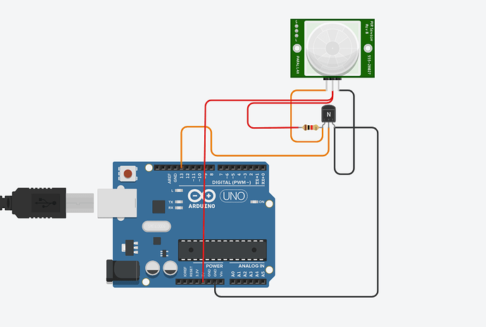
In the first diagram, I held the input pin low, and tried using the transistor to switch on and off the ENTIRE RELAY module.
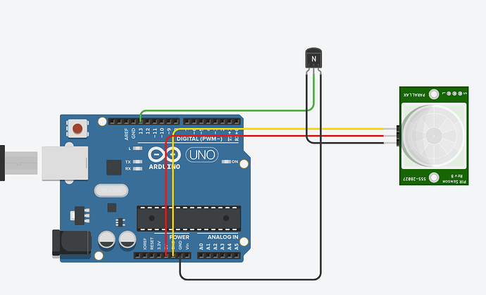
In the Second diagram, I used the circuit of a logic inverter to invert the Signals(which I didn't care about) and also BOOST the input voltage to around 5v(which I did care about), without any success in either of the circuits.
Uh... I wrote this answer in the quick reply mode and don't see any button for attachments.
Okay! The schematic pictures will be in my next reply!


