Instrument landing system (ils)
- 1. INSTRUMENT LANDING SYSTEM (ILS) by BIKAS CHANDRA SADASHIV
- 2. • Introduction • The Uses of ILS • ILS Components • How Localizer Works • How Glide Path Works • Marker Beacons Topics To Be Covered
- 3. INTRODUCTION • Radio beam transmitter that provides a direction for approaching aircraft that tune their receiver to the ILS frequency
- 4. The Uses of ILS • To guide the pilot during the approach and landing. –Very helpful when visibility is limited • To provide an aircraft with a precision final approach. • To provide an aircraft guidance to the runway both in the horizontal and vertical planes.
- 5. ILS Components • ILS consists of Ground Installations and Airborne Equipments • There are 3 equipments for Ground Installations, which are: 1. Ground Localizer (LLZ) Antenna – To provide horizontal navigation 2. Ground Glide path (GP) Antenna – To provide vertical navigation 3. Marker Beacons – To enable the pilot cross check the aircraft’s height. • There are 2 equipments for Airborne Equipments, which are: 1. LLZ and GP antennas located on the aircraft nose. 2. ILS indicator inside the cockpit
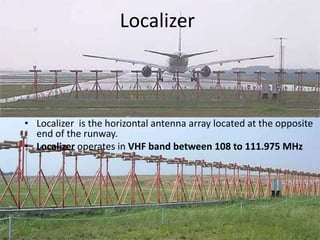
- 6. Localizer • Localizer is the horizontal antenna array located at the opposite end of the runway. • Localizer operates in VHF band between 108 to 111.975 MHz
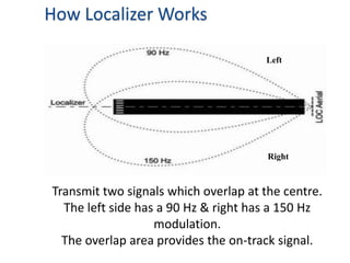
- 7. Transmit two signals which overlap at the centre. The left side has a 90 Hz & right has a 150 Hz modulation. The overlap area provides the on-track signal. Right Left How Localizer Works
- 8. Localizer Needle indicates direction of runway. Centered Needle = Correct Alignment
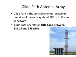
- 9. Glide Path Antenna Array • Glide Path is the vertical antenna located on one side of the runway about 300 m to the end of runway. • Glide Path operates in UHF band between 329.15 and 335 MHz
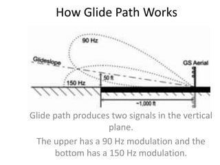
- 10. How Glide Path Works Glide path produces two signals in the vertical plane. The upper has a 90 Hz modulation and the bottom has a 150 Hz modulation.
- 11. Glide Path Needle indicates above/below glide path. Centered Needle = Correct Glide path
- 12. Marker Beacons • Marker beacons operating at a carrier frequency of 75 MHz are provided. • When the transmission from a marker beacon is received it activates an indicator on the pilot's instrument panel. • The correct height the aircraft should be at when the signal is received in an aircraft.
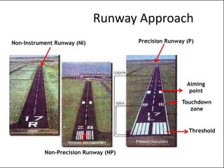
- 13. Runway Approach Non-Instrument Runway (NI) Non-Precision Runway (NP) Precision Runway (P) Threshold Touchdown zone Aiming point
- 14. Types of Runway Approach 1.Non-Instrument Runway (NI) – A runway intended for the operation of aircraft using visual approach procedure 2. Instrument Runway – A runway intended for the operation of aircraft using instrument approach procedures a) Non-Precision Runway (NP) • An instrument runway served by visual aids and a non-visual aid providing at least lateral guidance adequate for a straight-in approach b) Precision Runway (P) • Allow operations with a decision height and visibility
- 15. How ILS works? • Ground localizer antenna transmit VHF signal in direction opposite of runway to horizontally guide aircraft to the runway centre line. • Ground Glide Path antenna transmit UHF signal in vertical direction to vertically guide aircraft to the touchdown point. • Localizer and Glide Path antenna located at aircraft nose receives both signals and sends it to ILS indicator in the cockpit. • These signals activate the vertical and horizontal needles inside the ILS indicator to tell the pilot either go left/right or go up/down. • By keeping both needles centered, the pilot can guide his aircraft down to end of landing runway aligned with the runway center line and aiming the touch down.


