Attachments in implant retained overdentures/ cosmetic dentistry training
- 1. Attachments in implant retained overdentures INDIAN DENTAL ACADEMY Leader in continuing dental education www.indiandentalacademy.com www.indiandentalacademy.com
- 2. Introduction Many edentulous patients experience problems with their dentures, especially lack of stability and retention, together with a decrease of chewing ability. one possibilty of solving this problem is the use of endosseous implants to which an overdenture can be attached. www.indiandentalacademy.com
- 3. The overdenture approach facilitates the fabrication of different types of prostheses depending on the number of implants placed. They are • Implant-supported fixed screw-retained prosthesis • Implant-supported removable overdenture • Combined implant-retained and soft tissue-supported overdenture prosthesis www.indiandentalacademy.com
- 4. Definition of attachment A mechanical device for the fixation, retention, and stabilization of a prosthesis www.indiandentalacademy.com
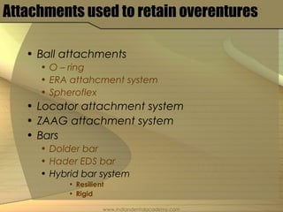
- 5. Attachments used to retain overentures • Ball attachments • O – ring • ERA attahcment system • Spheroflex • Locator attachment system • ZAAG attachment system • Bars • Dolder bar • Hader EDS bar • Hybrid bar system • Resilient • Rigid www.indiandentalacademy.com
- 6. • The decision as to what type of overdenture is given is determined by the following • Patients expectations • Financial considerations • Anatomic and morphologic condition of the bone • Shape of the alveolar ridge www.indiandentalacademy.com
- 7. Attachment selection based on number of implants and choice of prosthesis www.indiandentalacademy.com
- 8. Categorization of potential implant site in mandible – By Carl E Misch www.indiandentalacademy.com
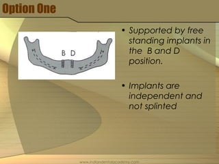
- 9. Option One • Supported by free standing implants in the B and D position. • Implants are independent and not splinted www.indiandentalacademy.com
- 10. • Indications •Indicated only when cost is the significant patient factor •When span between implants is too long •When insufficinet space exists to accommodate attachment to bar •Arch form that is tapered anteriorly so that bar is cantilevered posteriorly www.indiandentalacademy.com
- 11. • Most common type of attachment used is a Ball, ring type attachment. Eg: - O-Ring ERA attachment Spheroflex www.indiandentalacademy.com
- 12. O – ring attachment • They are doughnut shaped, synthetic polymer objects that posses the ability to bend with resistance and then return back to their original shape. • The O-ring attaches to a post with a groove or undercut area. www.indiandentalacademy.com
- 13. advantages • Ease in changing the attachment • Wide range of movement • Low cost • Different degrees of retention • Elimination of time and cost of a superstructure of a prosthesis www.indiandentalacademy.com
- 14. ERA • Resilient precision overdenture attachment • Universal hinge with vertical movement • Metal jacket which holds the male attachments www.indiandentalacademy.com
- 15. • Four angles to accommodate divergent implants (0, 5, 11, 17 degrees) • Two types standard and micro. Selected based on interocclusal distance. www.indiandentalacademy.com
- 16. Spheroflex • The Sphero Flex is a self paralleling combination titanium implant abutment and ball attachment. It is the ball attachment of choice for all implants. www.indiandentalacademy.com
- 17. Spheroflex • Self paralleling Implant abutment overdenture system with 2.5mm Ø sphere. • Free rotation of 7.5º for one abutment, 15º degrees for more than one. www.indiandentalacademy.com
- 18. Loactor Implant attachments • Supraradicular design which comes in a straight abutment and 2 angle conncections of 10 and 20 degrees for angled abutments. • Total height is 3.5 mm www.indiandentalacademy.com
- 19. • The Self-Aligning feature of the LOCATOR attachment allows a patient to easily seat their overdenture • Different retentive males that allow for choice of retention according to need of patient www.indiandentalacademy.com
- 20. • Indicated when • Interocclusal height is deficient • Guide plane is necessary because of minimal ridge height from alveolar bone loss. www.indiandentalacademy.com
- 21. • Locator female component on implant • Male component placed on the female component www.indiandentalacademy.com
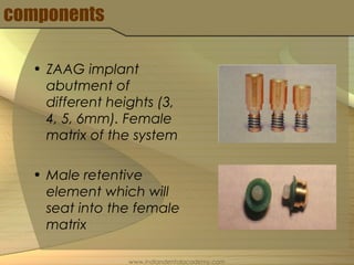
- 22. Zaag attachment systems • In 1972 Zest anchor was introduced to the dental profession. Initially used as an attachment for overdentures on natural teeth. • Later modified as ZAAG(Zest Anchor Advanced Generation) • Allows upto 15 degees of divergence in female orientation www.indiandentalacademy.com
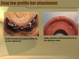
- 23. components • ZAAG implant abutment of different heights (3, 4, 5, 6mm). Female matrix of the system • Male retentive element which will seat into the female matrix www.indiandentalacademy.com
- 24. Female abutments in place Male retentive part seated Male retentive part placed and cured in the denture base www.indiandentalacademy.com
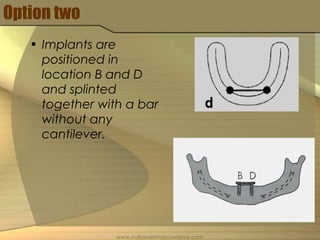
- 25. Option two • Implants are positioned in location B and D and splinted together with a bar without any cantilever. www.indiandentalacademy.com
- 26. • The attachment used here is a clip which is used to engage the bar • Bar is ovoid in shape and should be placed 2mm away from the soft tissue. www.indiandentalacademy.com
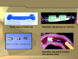
- 27. Hader bar • Developed by Hemet Hader in the late 1960’s. • Modified by English, Staubli to EDS Hader system. Height of the EDS hader bar is 3 mm. www.indiandentalacademy.com
- 28. Plastic form of Hader bar Retentice clip placed on cast bar Retentice clip being inserted into denture base www.indiandentalacademy.com
- 29. Option three • Three root form implants are used. The superstructure connects the three implants but without a distal cantilever. • Usually advocated in V shaped ridges www.indiandentalacademy.com
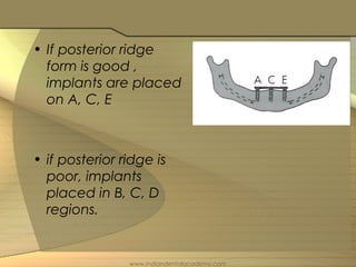
- 30. • The posterior ridge form determines the lateral movement of the restoration • Poor lateral stability places more stresses on the anterior implants www.indiandentalacademy.com
- 31. • If posterior ridge form is good , implants are placed on A, C, E • if posterior ridge is poor, implants placed in B, C, D regions. www.indiandentalacademy.com
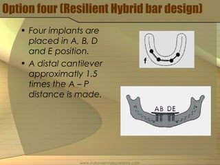
- 32. Option four (Resilient Hybrid bar design) • Four implants are placed in A, B, D and E position. • A distal cantilever approximatly 1.5 times the A – P distance is made. www.indiandentalacademy.com
- 33. • Attachments placed in the distal cantilever end and the midline. • Anterior attachment must allow prosthesis to lift from the bar to permit rotation of distal attachments. www.indiandentalacademy.com
- 34. • Indicated in patients who have • Poor posterior anatomy • Attachment placed in the anterior section is a clip and in the distal cantilever ball type attachments might be placed. • Patient benefits because there is greater vertical support and lateral stability. www.indiandentalacademy.com
- 35. Zaag low profile bar attachment ZAAG female part placed directly on the abutment Male retentive element placed on the denture base www.indiandentalacademy.com
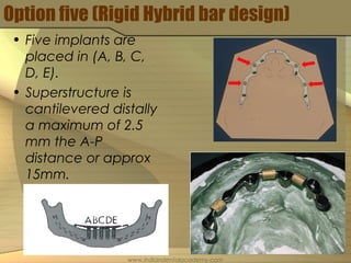
- 36. Option five (Rigid Hybrid bar design) • Five implants are placed in (A, B, C, D, E). • Superstructure is cantilevered distally a maximum of 2.5 mm the A-P distance or approx 15mm. www.indiandentalacademy.com
- 37. Loactor bar attachment • Four evenly placed Locator female attachment cast on superstructure in overdenture option - four www.indiandentalacademy.com
- 38. • Four to six retentive elements are included in the bar design. Attachments sually used are Hader clips, O – ring, ERA. • Typically four attachments are placed evenly. Two anterior and two posterior. www.indiandentalacademy.com
- 39. Thank you For more details please visit www.indiandentalacademy.com www.indiandentalacademy.com

