Abstract
Biochemical network maps are helpful for understanding the mechanism of how a collection of biochemical reactions generate particular functions within a cell. We developed a new and computationally feasible notation that enables drawing a wide resolution map from the domain-level reactions to phenomenological events and implemented it as the extended GUI network constructor of CADLIVE (Computer-Aided Design of LIVing systEms). The new notation presents ‘Domain expansion’ for proteins and RNAs, ‘Virtual reaction and nodes’ that are responsible for illustrating domain-based interaction and ‘InnerLink’ that links real complex nodes to virtual nodes to illustrate the exact components of the real complex. A modular box is also presented that packs related reactions as a module or a subnetwork, which gives CADLIVE a capability to draw biochemical maps in a hierarchical modular architecture. Furthermore, we developed a pathway search module for virtual knockout mutants as a built-in application of CADLIVE. This module analyzes gene function in the same way as molecular genetics, which simulates a change in mutant phenotypes or confirms the validity of the network map. The extended CADLIVE with the newly proposed notation is demonstrated to be feasible for computational simulation and analysis.
INTRODUCTION
A cell orchestrates biochemical reactions to form a molecular network that generates particular cellular functions in tissues or environment. It is important to elucidate not only the function of each individual interaction but also that of the associated pathways as a whole. Biochemical network maps are expected to organize a variety of biochemical reactions or biological knowledge in an accurate, complete and comprehensive manner. Such pathway maps play a key role in exploring gene function or the mechanism of how network architectures generate a particular cellular function.
A universal graphical notation is necessary for diagrams of biochemical networks that could be used worldwide as well as electronic circuit diagrams (http://wwwsbgnorg.). The graphical diagrams are helpful for predicting possible experimental results or for sharing the common understanding of biochemical models among scientists. Graphical notations require two features: one is a diagram-based network map that can be readily understood by humans; the other a text-based database that can be automatically processed by computers. They need to be implemented by a graphical user interface (GUI) to describe or draw biochemical network maps in a simple manner, which eliminates the need for laborious, time-consuming and annoying activities typically involved in this process.
With an increase in the number of biochemical interactions, there is a great need for computational tools with standard diagram notations for drawing a variety of biochemical reactions such as transcription, translation, transport, binding, modification and metabolic reactions(1–7). Such notations require defining explicit models of molecular networks for computer simulation or organizing available information on molecular interactions that encompasses the possible processes or pathways and combinatorially complex processes.
Among many diagram notations two types are the mainstream: molecular interaction maps (MIMs) (8) and process diagrams (3–5). Two criteria mainly feature these diagram notations: one is the temporal order of reactions and the other is the compact drawings. Process diagrams explicitly draw reaction flows in the temporal order. By contrast the MIMs employ the entity relationship model that would distinguish various types of molecular interactions rather than reaction flows. The MIMs that are presented by Kohn can cover three types of maps: explicit MIM models that draw all reactions explicitly by arrows and edges, heuristic MIM models that organize the available information about molecular interactions, and combinatorial MIM models that describe combinatorially complex reactions(9). Concerning compact drawings, graphical notations can be classified depending on whether named elementary symbols are allowed to repeatedly appear on a map. Most process diagrams allow the named elementary symbols to repeatedly appear on a map and directly or intuitively illustrate the process of how reactions proceed with little or no description in accompanying text. By contrast, a major consideration for the entity relationship model or the MIMs is the capability to trace all known interactions of any given molecular species. Accordingly, each molecular species ideally appears only once in a diagram and all interactions involving those species emanate from a single elementary symbol. Thus, the MIM model enables drawing complex reactions in compact space. At present process diagrams have been implemented by several software suits to draw biochemical maps (4,5,10), while there are only a few computational tools that implement the MIMs (7).
Biochemical networks must be handled in wide resolution from a fine-grained level in biochemistry to a coarse-grained level in postgenomic data or phenomenological events. Postgenomic technology infers a large-scale map of gene interaction networks or generates a protein–protein interaction map, while advanced biochemistry intensively studies molecular interactions at the domain levels of proteins or RNAs. In general, protein function changes, depending on which domains or sites are modified or bound by regulatory factors. There are many interaction or modification sites that have diverse effects on function and the potential number of modification-multimerization combinations is tremendous (2,11). Thus, it is important to draw molecular networks at the domain level.
In terms of the increased size of biochemical networks, MIMs are promising notations because they compactly place lots of interactions from the domain level reactions to the phenomenological events. However, the domain-level notation of MIMs has not yet been implemented into a computer application probably due to complexity of domain-level notations. It is required to propose a logical or computationally feasible MIM notation at the domain level.
The CADLIVE GUI network constructor had been presented as a software suite for drawing large-scale biochemical reactions in computer (7). It basically improves the explicit MIM model for computer edition of a network map and computer simulation, thus it has a characteristic feature of process diagrams where all reaction pathways can be traced in the temporal order. Thus, CADLIVE is able to draw biochemical reactions within compact space in the temporal order of reactions. However, CADLIVE has not presented the domain-level notation yet. There has been no computational tool that draws MIMs at the domain level. To draw biochemical maps at the domain levels, we have proposed a novel and computationally feasible notation and implemented it into CADLIVE. The new notation enables CADLIVE to draw a wide resolution map from the domain-level reactions to phenomenological events. A modular box is also presented that packs related reactions as a module or a subnetwork, which gives CADLIVE a capability to draw biochemical maps in a hierarchical modular architecture. Furthermore, as a useful analyzer of CADLIVE-built network maps we have developed a pathway search module for virtual knockout mutants. This module demonstrates that the extended CADLIVE is feasible for computer simulation.
MATERIALS AND METHODS
Improved notation of CADLIVE
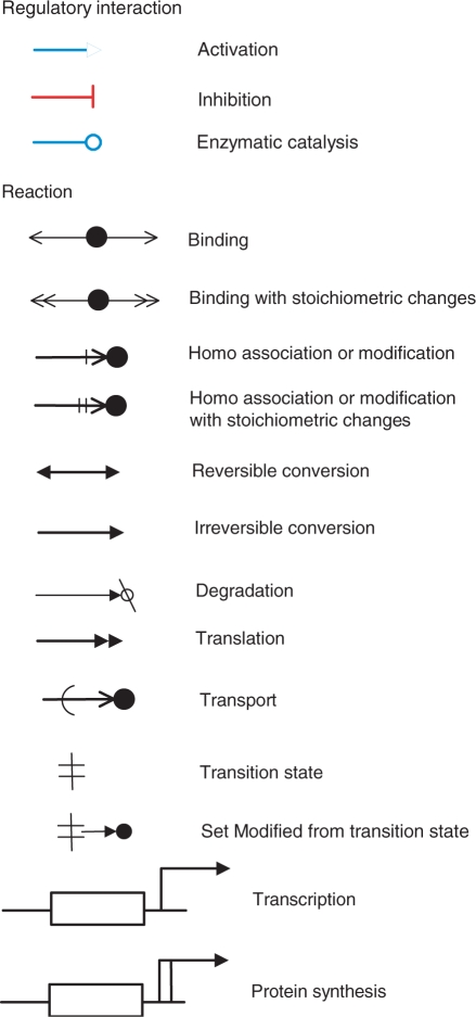
The previous version of the CADLIVE network constructor was a software suite for drawing a large-scale map of molecular interactions and for registering their associated regulator-reaction equations (RREs) in an extension of SBML level 2 (7,12). Notice that the previous version neither presents any method for the domain-level drawings nor does implement any pathway analyzer. CADLIVE basically improves Kohn's explicit MIM notation in terms of computer simulation, which describes signal transduction pathways and metabolic circuits in a form that can be readily processed by both computers and humans. Thus, CADLIVE enables compactly drawing complex reactions in the temporal order of reactions, such as multicomplex formation, protein modification, regulation of transcription and transport between organelles. The previous notations for CADLIVE are improved as shown in Figure 1, where some reaction arrows are revised to clearly distinguish their reactions.
Figure 1.
Improved graphical notation for regulators and reactions. The previous version of CADLIVE was improved to make clear the type of reactions. The regulator arrows are colored. The arrows of ‘homo association and modification’ and ‘homo association and modification with stoichiometric changes’ are revised. The reaction of ‘Set Modified from transition state’ is newly added.
The RREs and their associated graphical notation represent not only known interactions but also ambiguous reactions or phenomenological events, as shown in Supplementary Table 1. The RRE is described by:
where a reaction process is divided into the regulator part and the associated regulated reaction. The regulator is classified as one of three different categories: enzyme (-o), activator (->>), or inhibitor (-II).
Newly designed notations at the domain level
Biochemical networks can be drawn in wide resolution from domain-based interactions to phenomenological events. The phenomenological events can be regarded as some of the semantic interactions that are meaning flows of the reactions or events whose molecular mechanisms are not clear, e.g. gene interactions inferred from a DNA microarray and protein–protein interactions. The domain-based reactions indicate the interaction of how proteins and RNAs are assembled or modified at particular domains or sites. Many cellular functions are performed by domains being modified, e.g. the functions of p53 protein change depending on which domains are modified or bound by some regulatory factors. Thus, it is important to illustrate multiple domains of proteins and RNAs.
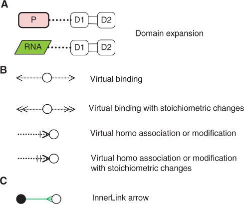
We propose a new notation together with a computational tool that enables CADLIVE to draw domain-level maps as shown in Figure 2. The new notation is provided as the addition to the previous or improved notation (Figure 1). It consists of ‘Domain expansion’ for proteins and RNAs, ‘Virtual reaction and nodes’ that are responsible for illustrating domain-based interactions, and ‘InnerLink’ that links real complex nodes to virtual nodes to illustrate the exact components of the real complex.
Figure 2.
New notations in CADLIVE. These notations enable drawing a biochemical network at the domain or subunit level. (A) Protein P or RNA is expanded into two domains or two subunits (D1 and D2). (B) Virtual reactions and nodes. (C) The InnerLink arrow connects the real complex node (filled circle, source species) to the virtual node (open circle, target species) to illustrate the exact components of the real complex.
Domain expansion
Protein complexes, proteins or RNAs can be expanded into subunits or domains that behave as a functional entity (Figure 2A). The domain is an element of overall structure that has a particular biological function independently. Many domains are not unique to the protein products but instead appear in a variety of proteins. Domains are often named and singled out because they figure prominently in the biological function of the protein they belong to. The domain or subunit denotes the binding site or functional site of RNAs, proteins, or complexes. Each domain or subunit can be named and linked to Virtual reactions and nodes to illustrate domain-level or subunit-level interactions.
Virtual reactions and nodes
Virtual reactions and nodes are employed to explain details of the process of complex formation and modification at the domain level, illustrating which domains are modified or assembled. Virtual reactions are always employed together with the virtual nodes. They do not really occur but just indicate which domains are modified or bound by other molecules or domains. They are literally virtual. As shown in Figure 2B, the notation consists of four virtual reactions: virtual_binding, virtual_binding_with_stoichiometric_changes, virtual_homo_association_or_modification, and virtual_homo_association_or_modification_ with_stoichiometric_changes.
Link of a real node to virtual nodes
InnerLink is designed as the arrow that links the real species to the virtual ones, which tells how the real molecule is modified or assembled (Figure 2C). The InnerLink arrows emanate just from a real complex or modified node, which is named a source species, to connect target virtual or real nodes. InnerLink illustrates that the source species includes the linked nodes or indicates the exact components of the source species.
Instruction of how to use Domain expansion, Virtual reactions and nodes and InnerLink
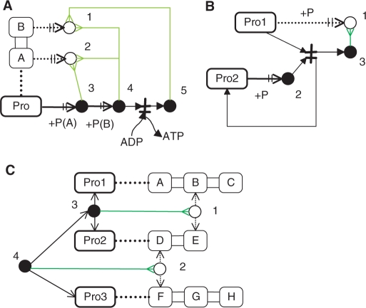
To explain how the new notations are applied to drawings of a biochemical network map, we present three examples as shown in Figure 3.
Figure 3.
Example models for presenting how to use the new notation. (A) Phosphorylation reactions at the domain level. The protein of Pro is expanded into the domains of A and B. 〈1〉 The virtual node indicates the state that Pro is phosphorylated on the B domain. 〈2〉 The virtual node indicates the state that Pro is phosphorylated on the A domain. 〈3〉 The real node of phosphorylated Pro (Pro-P) is produced. The InnerLink arrow (green) shows that the A domain is phosphorylated. 〈4〉 The real node of Pro-P-P is produced. The InnerLink arrow shows both the A and B domains are phosphorylated. 〈5〉 The real node of Pro-P is produced by dephosphorylation of Pro-P-P. The InnerLink arrow indicates the B domain is phosphorylated. (B) A phosphorus exchange reaction (Pro1 + Pro2-P -> Pro1-P + Pro2). 〈1〉 The virtual node indicates the state that Pro1 is phosphorylated. 〈2〉 The real node of Pro2-P is produced. 〈3〉 The InnerLink arrow indicates that the real node is Pro1-P. (C) Synthesis of the protein complex of Pro1:Pro2:Pro3. 〈1〉 The virtual node indicates the state that the B domain of Pro1 is bound to the E domain of Pro2. 〈2〉 The virtual node indicates the state that the D domain of Pro2 is bound to the F domain of Pro3. 〈3〉 The real node of Pro1:Pro2 is produced. The InnerLink arrow indicates that the B domain of Pro1 is bound to the E domain of Pro2. 〈4〉 The real node of Pro1:Pro2:Pro3 is produced. The InnerLinik arrow indicates that the D domain of Pro2 is bound to the F domain of Pro3.
Phosphorylation of domains
As shown in Figure 3A the protein with two phosphorylation sites: the domain A and domain B are illustrated. The A and B domain of the protein are phosphorylated in turn, then the B domain is dephosphorylated, which results in Protein-P(A). To visualize which domains are modified, we employ Virtual reaction and nodes with InnerLinks. Each phosphorylated protein has the InnerLink pointing to the virtual nodes, indicating which domains are modified.
Phosphorus exchange reaction
As shown in Figure 3B the exchange reaction of a phosphate group, Pro1 + Pro2-P → Pro1-P + Pro2, exemplifies the use of Virtual reaction and nodes with InnerLink. Phosphorus is exchanged from Pro2-P to Pro1, where the ATP-dependent phosphorylation of Pro1 does not occur. Instead, the virtual node of Pro1-P is displayed by the virtual reaction that Pro1 is phosphorylated. The function of ‘Set Modified Molecule’ makes a modified molecule arbitrarily from the transition state. Using this function, the filled circle of the Pro1-P is created from the transition state. The filled circle points to the virtual node of Pro1-P, which indicates that the filled circle is Pro1-P. The virtual reactions are not the real ones but show the site of modification.
Protein binding and modification
As shown in Figure 3C, Pro1, Pro2 and Pro3 are expanded into the A, B and C domains, D and E domains, and F, G and H domains, respectively. Pro1 and Pro2 form the complex by the B domain being bound to the E domain. The InnerLink generated from this complex points to the virtual node, indicating that the B and E domains are bound. The complex of Pro1 and Pro2 binds to Pro3, forming the triple complex of Pro1:Pro2:Pro3. The InnerLink emanating from the triple complex shows that the D domain of Pro2 is bound to the F domain of Pro3. The virtual nodes and reactions show how the proteins are assembled at the domain level.
White and black boxes
CADLIVE is able to draw a wide resolution map from the domain level to a phenomenological event level on the ‘Network Constructor’ window. Since complicated drawings often make a network map complicated or confused, we present ‘WhiteBox’ that packs related nodes into a module or a subnetwork as shown in Figure 4. Since WhiteBox is able to include itself, biochemical networks can be drawn in a hierarchical modular architecture. WhiteBox is handled on the menu of ‘List of WhiteBox’. ‘BlackBox’ denotes the subnetwork whose molecular mechanisms or reactions are unknown. It is allowed to place an unknown subnetwork as a BlackBox symbol. BlackBox is edited in the same manner as the species.
Figure 4.
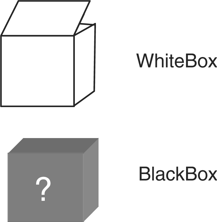
New notations for drawing modular architectures or unknown modules.
Separation of real reactions and nodes from a domain level map
In CADLIVE the computational function of the notation consisting of the real reactions and nodes is definitely separated from that of the newly presented notation involving the domain expansion and virtual reactions and nodes. This functional separation protects the RREs, which are provided by the real reactions and nodes, from being interfered by the virtual reactions and nodes. The RREs basically correspond to the real reaction and nodes. The newly presented notation plays a complementary or optional role in intelligibly illustrating the interactions at the domain level. Thus, CADLIVE is able to switch off the new notations from the screen as shown in Supplementary Figure 1.
Computer simulation
In order to demonstrate the applicability of the CADLIVE notation to computer simulation and to provide convenient computational tools, we developed the pathway search module for virtual knockout mutants, which enables exploration of gene function as well as gene knockout experiment in molecular biology or molecular genetics. Details of the algorithm and implementation are shown in Supplementary Figures 2–5. The modules for pathway search and virtual gene knockout utilize the real reactions and nodes described by RREs.
GUI application of the extended CADLIVE
All the functions of the CADLIVE network constructor are written in JAVA and are available from the screen shown in Supplementary Figure 6. Each process of map drawings and pathway search for virtual knockout mutants is shown in Supplementary Figures 7–11. This version is 2.75. CADLIVE with the detailed instruction is freely available from: http://www.cadlive.jp.
Summary of the extended CADLIVE network constructor
We summarize the notation and computational functions implemented by the extended CADLIVE.
CADLIVE draws biochemical reactions in the temporal order and in principle a molecular species appears in only one place on a map.
Molecular interactions are two types: regulators (contingency or modifier) and reactions. Contingency is used in Kohn's MIM maps and has almost the same definition as CADLIVE.
Molecular interactions are shown by different types of arrows, which are readily distinguished by different arrowheads.
Elementary species are associated with various symbols and are named, while a small filled circle represents the complex or modified molecule.
A small filled circle on a reaction arrow indicates the product of the reaction. The species type of the circle is distinguished by the reaction arrows.
Complexes, proteins or RNAs are expanded into multiple subunits or domains.
Virtual reactions and nodes are presented to illustrate the domains or sites to be modified or assembled, enabling a fine-grained resolution map.
InnerLink that emanates from a source species is presented to illustrate the exact components that constitute the source species.
WhiteBox packs related reactions into subnetworks or modules and enables visualizing biochemical networks in a hierarchical manner.
Since biological reactions are exactly defined, CADLIVE prohibits drawing the reactions that are unlikely to occur in terms of biology.
The function for drawing the real reactions and nodes are separated from that for the virtual reactions and nodes and the domain expansion.
The pathway search analyzer for virtual knockout mutants is implemented, where the real reactions and nodes are employed to perform such analyses.
Biochemical maps
Mammalian translation initiation system
To demonstrate the function of the new notations: Domain expansion, Virtual reactions and nodes, InnerLink and WhiteBox, we employ a mammalian translation initiation system as a biochemical network model (13–15). Translation is the process by which the information contained in mRNA is used to synthesize a polypeptide. The polypeptide can be assembled once RNA binds to a ribosome. The translation consists of a series of multiple reaction steps and relates a variety of molecules such as RNAs, proteins and metabolites, forming a complex system. Details of the biochemical network map are explained in Supplementary Text 1.
p53 and Mdm2 system
To compare CADLIVE with the Kohn's MIMs(17), we draw the biochemical map of the p53 and Mdm2 network by using CADLIVE. The biochemical network is the same as presented by Kohn. The tumor suppressor protein p53 and its partner Mdm2 play a major role in providing a robust property to DNA damage. These two proteins are the network hubs that integrate signals from growth stimulus, DNA damage, or replication status. Defects of these proteins definitely lead to cancer. The p53-Mdm2 system controls their activities and regulates expression of genes that stop cell cycle progression or induce apoptosis.
RESULTS
Application to a mammalian translation initiation system
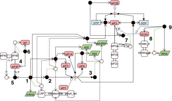
A biochemical network map in a mammalian translation initiation system is successfully drawn at the domain level as shown in Figure 5. An mRNA is expanded into the cap structure, initiation site and poly(A) tail. The complex (filled circle) 〈1〉 points to the virtual node (white circle) through the InnerLink arrow, indicating that the cap of the mRNA binds the 40S ribosome complex with eIF3:eIF1A and the Met-tRNAi:eIF2:GTP. The complex 〈2〉 points to the virtual node through InnerLink, indicating that the initiation site of the mRNA binds the 40S complex with eIF3:eIF1A and Met-tRNAi:eIF2:GTP. The complex 〈3〉 is linked to the virtual node by InnerLink, indicating that the complex consists of 40S, 60S, the initiation site of the mRNA and Met-tRNAi. This initiation complex is produced by eIF5. The protein complex of eIF4F 〈4〉 has the eIF4E and eIF4G subunits. These subunits are drawn in the same manner as the domain expansion method. The modified molecule of eIF4-P 〈5〉 points to the virtual node by InnerLink, indicating that the subunit eIF4E is phosphorylated. The binding complex of eIF4:BP 〈6〉 is linked to the virtual node by InnerLink, indicating that the eIF4E subunit binds to BP. The protein complex of eIF2 is expanded into three subunits: eIF2α, eIF2β and eIF2γ. The modified protein of eIF2-P 〈7〉 points to the virtual node by InnerLink, indicating that the serine 51 site of the eIF2α subunit is phosphorylated by GCN2. The GCN2 protein 〈8〉 has two domains: a kinase domain and RNA-binding domain. The phosphorylation activity of GCN2 is activated by the complex 〈9〉, which is linked to the virtual node by InnerLink, indicating that the tRNA binds to the binding domain of GCN2.
Figure 5.
A biochemical network map of the mammalian translation initiation system. This map is drawn by the extended CADLIVE GUI editor.
As shown in Supplementary Figure 8, WhiteBox is employed to decompose the entire translation initiation model into functional modules in hierarchical structure. The translation initiation model is divided into 6 modules: the eIF2 module, the ribosome module, the eIF4 module, the GCN2 module, the eIF5 module and the mRNA complex module. The ribosome module is further decomposed into two modules: the 40S module and the 60S module.
Comparison with Kohn's notation
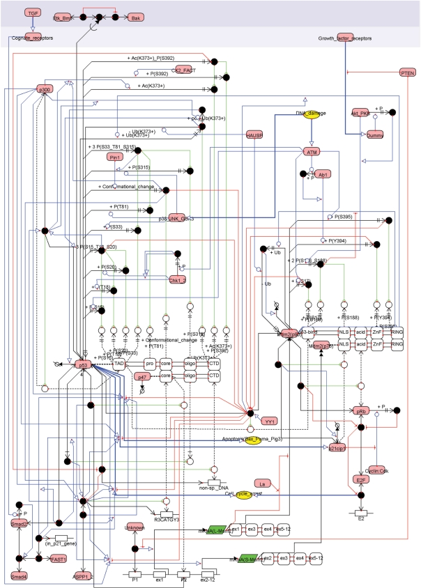
To compare the notation of CADLIVE with Kohn's MIMs, we drew the same p53 map as he presented elsewhere(16). As shown in Figure 6, the new notations of the Domain expansion, Virtual reactions and nodes and InnerLink enabled drawing the domain level functions of p53 that are changed by a variety of phosphorylation sites. However, there are two major inconsistencies between CADLIVE and Kohn's notations. One is that CADLIVE definitely needs specifying the temporal order to place a complex species, while the MIMs do not. The other is that CADLIVE allows for the explicit model but does not allow for heuristic and combinatorial interpretation.
Figure 6.
A biochemical map of p53 drawn by the extended CADLIVE. Details of the map are clearly displayed by using the extended CADLIVE GUI editor.
Here we show how CADLIVE overcomes these inconsistencies. We present a solution for the first problem by using a plain example as shown in Figure 7A. If a protein is phosphorylated at two domains, use of Kohn's MIM readily places this phosphorylated protein. On the other hand, the CADLIVE needs a device to draw the phosphorylated protein, because the CADLIVE notation is based on the temporal order from the named species, i.e. it must show the reaction order of how two domains are phosphorylated. To solve this problem, we use an unknown factor of X to place the phosphorylated protein as shown in Figure 7B. By using this device, CADLIVE is able to draw the domain modification without indicating any explicit reaction order.
Figure 7.
Demonstration of how the notation of the extended CADLIVE corresponds to that of the explicit MIM of Kohn's. (A) Kohn's notation. Species A is expanded into the D1 and D2 domains. The filled circle 〈1〉 is A-P-P whose D1 and D2 domains are phosphorylated. This map does not show how the product 〈1〉 is produced. (B) CADLIVE notation. Since CADLIVE must show how a product is produced from an elementary species, we assume that the product of A-P-P is produced by unknown factors of X, where we do not show any mechanism of how it is produced. The filled circle 〈2〉 indicates A-P-P where the D1 and D2 domains are phosphorylated. The filled circles of 〈1, 2〉 are the same species and the new notation of CADLIVE replaces the domain description by Kohn.
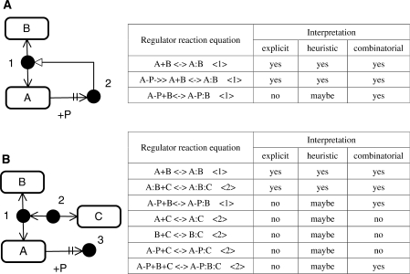
Second, CADLIVE, which has originally been developed for computer simulation, does not still present the heuristic and combinatorial MIMs, while Kohn's notation allows for them. If CADLIVE draws all possible interactions and molecules provided by heuristic and combinatorial MIMs, it will need much more space, whereby making a map very complicated or confused. We present an idea to avoid this problem. Since the notation of complex formation in CADLIVE is designed based on Kohn's MIMs, it is possible to apply heuristic or combinatorial interpretation to the CADLIVE map, as exemplified by Figure 8. If heuristic or combinatorial interpretation is applied to the CADLIVE map, users can understand the p53 map in the similar manner to Kohn's notation (Figure 6). However, notice that the RREs generated by CADLIVE correspond to the explicit MIM but does not to the heuristic and combinatorial MIMs. The heuristic and combinatorial interpretations cannot be used for computer simulation.
Figure 8.
Example models of the explicit, heuristic and combinatorial interpretation in CADLIVE. Tyree types of interpretation for the reactions are described in the side table. The number in the parentheses in the tables indicates the product species in the figures. For any RRE, interpretation is stated as, ‘yes’, ‘no’, or ‘maybe’. ‘Yes’ and ‘no’ mean that the reaction occurs and does not, respectively, which depends on the employed interpretation. In the heuristic column, ‘maybe’ means that it is not known whether the products marked by the number are synthesized. Although the notation of CADLIVE has originally been designed as an explicit MIM, it is possible to apply heuristic and combinatorial interpretation to a map of CADLIVE, because the CADLIVE notation is built based on Kohn's MIM. Note that the RREs generated by the CADLIVE editor correspond to the explicit MIM but does not to the heuristic and combinatorial MIMs.
Feasibility of computational pathway analysis
To demonstrate that the extended CADLIVE performs computational analysis, we apply pathway analysis to two biochemical networks: a budding yeast cell cycle network and an Escherichia coli ammonia assimilation system. In the former model, we demonstrate the pathways search module confirms the validity of the biochemical network map or predicts its dynamic behavior (Supplementary Figure 12 and Supplementary Table 4). In the latter model, we show how redundant feedback loops generate robust properties to multiple gene deletions (Supplementary Figures 13 and 14, and Supplementary Table 5). This module is very useful for the pathway analysis of knockout mutants. The extended CADLIVE with the newly proposed notation is demonstrated to be available for computational simulation and analysis
DISCUSSION
Characterization of CADLIVE among several graphical notations
Many graphical notations(1–5,7) have been proposed to draw a biochemical network map and discussed to establish a global standard notation like engineering standards of architects, computers and electric circuits. Yet it will take further extensive investigation to unify it. Here we compare CADLIVE with other graphical notations from many aspects, e.g. the temporal order of reactions, compact drawings, resolution of a map, a variety of reactions, how to draw unclear reactions or non-mechanistic reactions and simulation-oriented notation, as described in Supplementary Table 6. The feature common to many notations is to employ the regulator (modifier, contingency)-reaction model where regulator symbols, such as activator, inhibitors and enzymes, act on reaction arrows. As major criteria that distinguish the graphical notations we refer the temporal order of reactions and compact drawings. Process diagrams including cell designer, patika (4) and BioD (5) employ the temporal order of reactions that readily enables computer simulation. CADLIVE also can draw all reactions in the temporal order because it emphasizes pathway exploration or dynamic simulation (17). By contrast, MIMs are the entity relationship models that can draw potentially possible interactions explicitly or implicitly without insisting on the temporal order of reactions. Regarding compact drawings, a decisive factor is whether redundant appearance of the named molecular symbols is allowed or not. Most process diagrams allow the named molecular symbols to repeatedly appear on a map, while Kohn's MIMs and CADLIVE present a filled circle drawing a complex molecule to avoid redundant appearance of the named molecular species. Thus, CADLIVE is characterized mainly by two features that enable drawing the temporal order of reactions for computer simulation (process diagram) and enable compact drawings that do not allow any redundant appearance of named molecular species (MIM).
We discuss the conceptual and technical differences between Kohn's MIMs and the CADLIVE notation. Kohn's MIM notations aim at presenting many electric maps of large-scale networks on the web in the same manner as KEGG (11), while they are neither implemented into computer application nor employ RREs. The MIMs are not used for computer simulation. On the other hand, the advantages of the CADLIVE notation are to readily enable computational edition of complicated pathways and to automatically convert a map into RREs in an SBML extension format. In addition, the drawings by CADLIVE are restricted to biologically possible reactions. This does not allow users to draw any biochemical reactions that are unlikely to occur in terms of biology, e.g. the translation arrow is not attached to metabolite symbols. This restriction greatly reduces errors in biochemical network maps. The CADLIVE notation also facilitates editing, updating and integrating large-scale biochemical maps, visualizes a map in a different way and performs computer simulation. The applicability of the extended CADLIVE to computational pathway analyses is demonstrated by using two biochemical network models (Supplementary Figures 12–14 and Supplementary Tables 4 and 5).
A new graphical notation of CADLIVE
A novel and computationally feasible notation at the domain level is implemented into the extended version of the CADLIVE network constructor. The new notation consists of three major functions: Domain expansion, Virtual reactions and nodes and InnerLink. Virtual reactions and nodes are not real ones but are used to just indicate which domains are modified or assembled. InnerLink connects such virtual nodes to the real complex species and illustrate all components of the complex molecules. Addition of the new notation enables CADLIVE to draw a wide resolution map from the domain level to phenomenological events. Furthermore, we presented another new function, WhiteBox, to pack related reactions into a module box or a subnetwork. This function is useful for revealing the hierarchical modular architecture of a map. An effective decomposition by WhiteBox leads to an understanding of modular architecture of biochemical networks.
In the field of software engineering the Unified Modeling Language (UML) are presented for object modeling. UML is a general-purpose modeling language that includes a standardized graphical notation used to create an abstract model of a system and uses a variety of diagrams, because a graphical diagram alone cannot readily describe details of large-scale and complex systems. A full understanding of biological functions of molecules, their associated pathway networks and dynamic behaviors generated by their networks may require a variety of graphical diagrams. At present, MIMs and process diagrams have been proposed to design biochemical networks. Each has a different function: the former emphasizes the molecular interactions and the latter indicates the signal or mass flow in molecular processes. CADLIVE has both features by adopting an explicit MIM with the temporal order of reactions. In the future, as well as UML we need to develop unified graphical diagrams to precisely understand the molecular architecture of biochemical systems, to represent common biological knowledge, or to rationally design a large-scale biochemical systems.
An integrative system for simulation
Designing the molecular interaction networks of a whole cell requires data convertibility among various databases because many reaction maps need to be integrated. Thus, the extended CADLIVE network constructor employs an SBML2-based representation, which provides the dynamic extensibility and configurability for CADLIVE, where components and reactions in RREs can be readily added, removed or exchanged among various systems. Due to the high readability of the data architecture, many applications (http://sbw.kgi.edu/) can be available for CADLIVE. This protocol gives CADLIVE the capability to plug-in many application modules through the RREs. CADLIVE has a great potential to integrate many network data and application software and will develop one of the most advanced and comprehensive tools for biological simulators.
The CADLIVE system is rapidly growing a comprehensive computational tool that consists of various application modules: the GUI network constructor (this article), the database that registers RREs, the pathway search module for virtual knockout mutants (this article), the network layout module that automatically draws biochemical networks from RREs (18), the dynamic simulator that automatically converts biochemical network maps into mathematical models, simulating and analyzing them (17), an integrator module for heterogeneous biological information(19). Once a biochemical network map is provided, the CADLIVE system analyzes its static and dynamic features effectively.
SUPPLEMENTARY DATA
Supplementary Data are available at NAR Online.
ACKNOWLEDGEMENT
We are grateful to Mitsui Knowledge Industry Co., Ltd for programming of the extended CADLIVE. This study is supported by The Project for Development of a Technological Infrastructure for Industrial Bioprocesses on R&D of New Industrial Science and Technology Frontiers by Ministry of Economy, Trade & Industry (METI), and entrusted by New Energy and Industrial Technology Development Organization (NEDO) and partially supported by the Ministry of Education, Science, Sports and Culture, Grant-in-Aid for Scientific Research (B) 2006, 18300098. Funding to pay the Open Access publication charges for this article was provided by the Ministry of Education, Science, Sports and Culture, Grant-in-Aid for Scientific Research (B) 2006, 18300098.
Conflict of interest statement. None declared.
REFERENCES
- 1.Kohn KW, Aladjem MI. Circuit diagrams for biological networks. Mol. Syst. Biol. 2006;2 doi: 10.1038/msb4100044. 2006 0002. [DOI] [PMC free article] [PubMed] [Google Scholar]
- 2.Blinov ML, Faeder JR, Goldstein B, Hlavacek WS. A network model of early events in epidermal growth factor receptor signaling that accounts for combinatorial complexity. Biosystems. 2006;83:136–151. doi: 10.1016/j.biosystems.2005.06.014. [DOI] [PubMed] [Google Scholar]
- 3.Kitano H, Funahashi A, Matsuoka Y, Oda K. Using process diagrams for the graphical representation of biological networks. Nat. Biotechnol. 2005;23:961–966. doi: 10.1038/nbt1111. [DOI] [PubMed] [Google Scholar]
- 4.Demir E, Babur O, Dogrusoz U, Gursoy A, Nisanci G, Cetin-Atalay R, Ozturk M. PATIKA: an integrated visual environment for collaborative construction and analysis of cellular pathways. Bioinformatics. 2002;18:996–1003. doi: 10.1093/bioinformatics/18.7.996. [DOI] [PubMed] [Google Scholar]
- 5.Cook DL, Farley JF, Tapscott SJ. A basis for a visual language for describing, archiving and analyzing functional models of complex biological systems. Genome Biol. 2001;2 doi: 10.1186/gb-2001-2-4-research0012. RESEARCH0012. [DOI] [PMC free article] [PubMed] [Google Scholar]
- 6.Mandel JJ, Fuss H, Palfreyman NM, Dubitzky W. Modeling biochemical transformation processes and information processing with Narrator. BMC Bioinformatics. 2007;8:103. doi: 10.1186/1471-2105-8-103. [DOI] [PMC free article] [PubMed] [Google Scholar]
- 7.Kurata H, Matoba N, Shimizu N. CADLIVE for constructing a large-scale biochemical network based on a simulation-directed notation and its application to yeast cell cycle. Nucleic Acids Res. 2003;31:4071–4084. doi: 10.1093/nar/gkg461. [DOI] [PMC free article] [PubMed] [Google Scholar]
- 8.Kohn KW. Molecular interaction map of the mammalian cell cycle control and DNA repair systems. Mol. Biol. Cell. 1999;10:2703–2734. doi: 10.1091/mbc.10.8.2703. [DOI] [PMC free article] [PubMed] [Google Scholar]
- 9.Kohn KW, Aladjem MI, Kim S, Weinstein JN, Pommier Y. Depicting combinatorial complexity with the molecular interaction map notation. Mol. Syst. Biol. 2006;2:51. doi: 10.1038/msb4100088. [DOI] [PMC free article] [PubMed] [Google Scholar]
- 10.Funahashi A, Morohashi M, Kitano H. CellDesigner: a process diagram editor for gene-regulatory and biochemical networks. Biosilico. 2003;1:159–162. [Google Scholar]
- 11.Kohn KW, Aladjem MI, Weinstein JN, Pommier Y. Molecular interaction maps of bioregulatory networks: a general rubric for systems biology. Mol. Bio.l Cell. 2006;17:1–13. doi: 10.1091/mbc.E05-09-0824. [DOI] [PMC free article] [PubMed] [Google Scholar]
- 12.Hucka M, Finney A, Sauro HM, Bolouri H, Doyle JC, Kitano H, Arkin AP, Bornstein BJ, Bray D, et al. The systems biology markup language (SBML): a medium for representation and exchange of biochemical network models. Bioinformatics. 2003;19:524–531. doi: 10.1093/bioinformatics/btg015. [DOI] [PubMed] [Google Scholar]
- 13.Asano K. Translational and transcriptional control by eIF2 phosphorylation: requirement for integrity of ribosomal preinitiation complex. Tanpakushitsu Kakusan Koso. 2006;51:389–398. [PubMed] [Google Scholar]
- 14.Hershey JW, Asano K, Naranda T, Vornlocher HP, Hanachi P, Merrick WC. Conservation and diversity in the structure of translation initiation factor EIF3 from humans and yeast. Biochimie. 1996;78:903–907. doi: 10.1016/s0300-9084(97)86711-9. [DOI] [PubMed] [Google Scholar]
- 15.Merrick WC, Hershey JWB. The pathway and mechanism of eukaryotic protein synthesis. In: Hershey JWB, Mathews MB, Sonnenberg N, editors. Translational Control. Cold Spring Harbor, NY: Cold Spring Harbor Laboratory Press; 1996. pp. 31–69. [Google Scholar]
- 16.Kohn KW, Pommier Y. Molecular interaction map of the p53 and Mdm2 logic elements, which control the Off-On switch of p53 in response to DNA damage. Biochem. Biophys. Res. Commun. 2005;331:816–827. doi: 10.1016/j.bbrc.2005.03.186. [DOI] [PubMed] [Google Scholar]
- 17.Kurata H, Masaki K, Sumida Y, Iwasaki R. CADLIVE dynamic simulator: direct link of biochemical networks to dynamic models. Genome Res. 2005;15:590–600. doi: 10.1101/gr.3463705. [DOI] [PMC free article] [PubMed] [Google Scholar]
- 18.Li W, Kurata H. A grid layout algorithm for automatic drawing of biochemical networks. Bioinformatics. 2005;21:2036–2042. doi: 10.1093/bioinformatics/bti290. [DOI] [PubMed] [Google Scholar]
- 19.Shimokawa Y, Maeda K, Inoue K, Kurata H. Proceedings of the 16th International Conference on Genome Informatics. Vol. 16. Tokyo: Universal Academy Press, Inc; 2006. CADLIVE: Integration for large-scale network data. S02-01-02. [Google Scholar]
Associated Data
This section collects any data citations, data availability statements, or supplementary materials included in this article.


